

Panasonic SAHT730 - DVD THEATER RECEIVER, SC-HT730, SC-HT930, SB-FS930, SB-WA930 Technical Manual
...Page 1
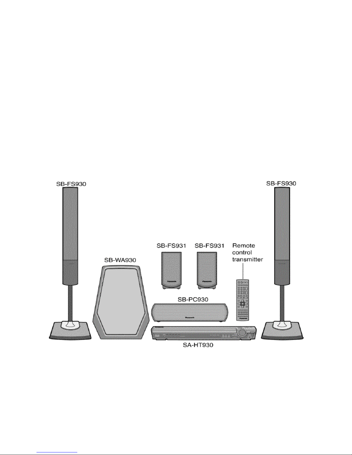
Technical Guide
5-DVD Changer Home Theater System
SC-HT730, SC-HT930 Models
Practical Servicing of
B02
1
Page 2

g
Prepared by
Herb Chin, & Joe Blanks
Panasonic Services Company
National Training
Panasonic is a registered trademark of Panasonic North America
"HDMI, the HDMI logo and High-Definition Multimedia Interface are trademarks or registered trademarks of HDMI Licensing LLC."
BBE, the BBE logo, Sonic Maximizer and High Definition Sound are registered trademarks or trademarks of BBE Sound, Inc.
Photoshop is a registered trademark of Adobe Systems Incorporated in the United States or other countries.
Dolby is a registered trademark of Dolby Laboratories.
DTS is a re
Copyright © 2006 by Panasonic Services Company
All rights reserved. Unauthorized copying and distribution is a violation of law.
istered trademark of Digital Theater Systems Corporation.
Warning
This service information is designed for experienced repair technicians only and is not designed for use by
the general public. It does not contain warnings or cautions to advise non-technical individuals of potential
dangers in attempting to service a product. Products powered by electricity should be serviced or repaired
only by experienced professional technicians. Any attempt to service or repair the product or products
dealt with in this service information by anyone else could result in serious injury or death.
SA-HT730 / SAHT930
2
Page 3

Table of Contents
OBJECTIVE............................................................................................................................. 4
I NO START-UP AND DVD TRANSPORT PROBLEMS................................................. 5
1. POWER-ON START-UP SEQUENCE – WHERE IS THE PROBLEM?........................................... 5
2. SENSORS, BELTS, AND MOTOR LOCATION ............................................................................ 6
3. SIMULATED FAILURE SYMPTOMS – QUICK FIXES................................................................. 7
4. TRAY REMOVAL FOR SENSORS, BELTS, & DIAGNOSTIC ACCESS......................................... 8
5. TRAY INSTALLATION (AFTER REPAIRS)................................................................................ 9
6. SENSOR TESTING ............................................................................................................... 10
Testing the Tray Loading Motor and Related Sensors .................................................... 10
Testing the Tray Rotation Motor and Related Sensors.................................................... 11
II SHUTDOWN PROBLEM................................................................................................ 12
PROTECTION CONCEPT – ALL THE SHUTDOWN POSSIBILITIES................................................12
Overall Repair Strategy ................................................................................................... 12
CONTROL UNIT REPAIR (SA-HT730 / SA-HT930) STRATEGY ............................................. 13
Control unit repair Procedure......................................................................................... 14
Jumper Paths to System Control IC2018 for Shutdown Problems.................................. 15
Control Unit Protection Concept.....................................................................................16
SUBWOOFER UNIT REPAIR (SB-WA730 / SA-WA930)........................................................17
Subwoofer Repair Strategy – Start by isolaating the problem......................................... 17
Subwoofer Repair Procedure........................................................................................... 18
Subwoofer Disassembly ................................................................................................... 20
Subwoofer Test / Operating Position............................................................................... 21
III NO AUDIO PROBLEMS ...............................................................................................22
How to trace down no audio (one or more channels)...................................................... 22
SA-HT730 / SAHT930
3
Page 4

Objective
This technical guide was prepared with the following objectives in mind:
• Provide the servicer with a brief overview of the concepts of operation for new
circuits employed in this line of models.
• Provide drawings with emphasis on signal path to simplify the task of signal
tracing and to locate the cause of a defect.
• Furnish troubleshooting procedures that contribute to a speedier repair of the
product.
• Provide examples of typical problems that may have occurred in similar types of
circuits.
SA-HT730 / SAHT930
4
Page 5

I No Start-Up and DVD Transport Problems
Model: SA-HT730 / HT930. Since this unit normally starts in DVD mode, start-up
symptoms are often caused by DVD transport problems – A failure in the DVD
transport stops the start up.
Servicing the DVD section is divided into 6 groups (pick and choose what you need):
1. Power-On Sequence 4. Tray Removal for Diagnostic Access
2. Sensors, Belts and Motor Location 5. Tray Installation (after Repairs)
3. Simulated Sensor Failure Symptoms 6. Sensor testing
Start with the power-on sequence. The power-on sequence is important for
identifying the section that does not start. Compare the sequence in the defective
unit to the correct sequence listed below in table 1. The step where the unit stops
working is where the problem is (or in the step just before). Testing the sensors is
the next diagnostic step (section 6) if the transport works but behaves out of
sequence. Section 2 locates the sensors. However access to the sensors for testing
is tricky but the trick is revealed in section 4 - tray removal. After repairs, section 5
shows how to align the gears for reassembly.
1. Power-On Start-Up Sequence – Where is the problem?
After AC is disconnected, the unit always powers on into the DVD operation mode.
SA-HT730 / HT930 Power ON sequence
Step Time Operation Display Proof
1. 0 AC input. Unit off.
2. 0 Press Power button Disc # 1-5 light in sequence.
3. 1 sec “Hello”
4. 4 sec Micro IC8001 controls laser
assembly via cable to
CN2004. See table 2.
5. 5 sec Loading motor moves the
Tray in (if S9001 is not open)
and into the disc unchucked
position using two loading
sensors.
No movement will occur if the
transport is already in this tray
in unchucked position.
6. 8
sec.
7. 17 Tray motor stops at original
1. Disc Tray motor rotates.
Slow rotation is first.
2. Detection of discs on platter
/ tray.
disc slot.
None
appears
“INIT” appears
“Please Wait”
“Please Wait”
“ No Disc”
Table 1
Red light over pwr button
(standby).
All disc numbers 1-5 light.
Disc proof sequence is followed *
see table 2.
Two loading sensors are used:
1. S9001 = contacts open / tray
closed. Contacts are open if the
Tray is in.
2. Q9001 at CN2011/6 = 0Vdc =
non-clamped position (tray
rotation is possible when the
disc assembly is unclamped.)
1. S9102 detects tray motor gear
rotation.
2. Q9103 detects each disc when
the disc blocks the Q9103 light.
S9101 also detects tray rot.
position.
SA-HT730 / SAHT930
5
Page 6
* Disc Proof Sequence (no disc loaded)
a) Sled moves to home position (at
center).
b) Sled moves out to DVD TOC
location.
c) Laser ON. h) Focus search 3X. 3. Volts missing
d) Focus search 3X. (spins if disc is
found)
e) Sled moves to home position (at
center).
f) Sled moves out to DVD TOC
location.
g) Laser ON. 2. Mechanical
i) Sled moves to home position 4. Traverse
j) Sled moves out to initial position. 5. IC8251 –
Table 2
Checkout
Failure
1. Ribbon cable
binding
Motor
motor drive
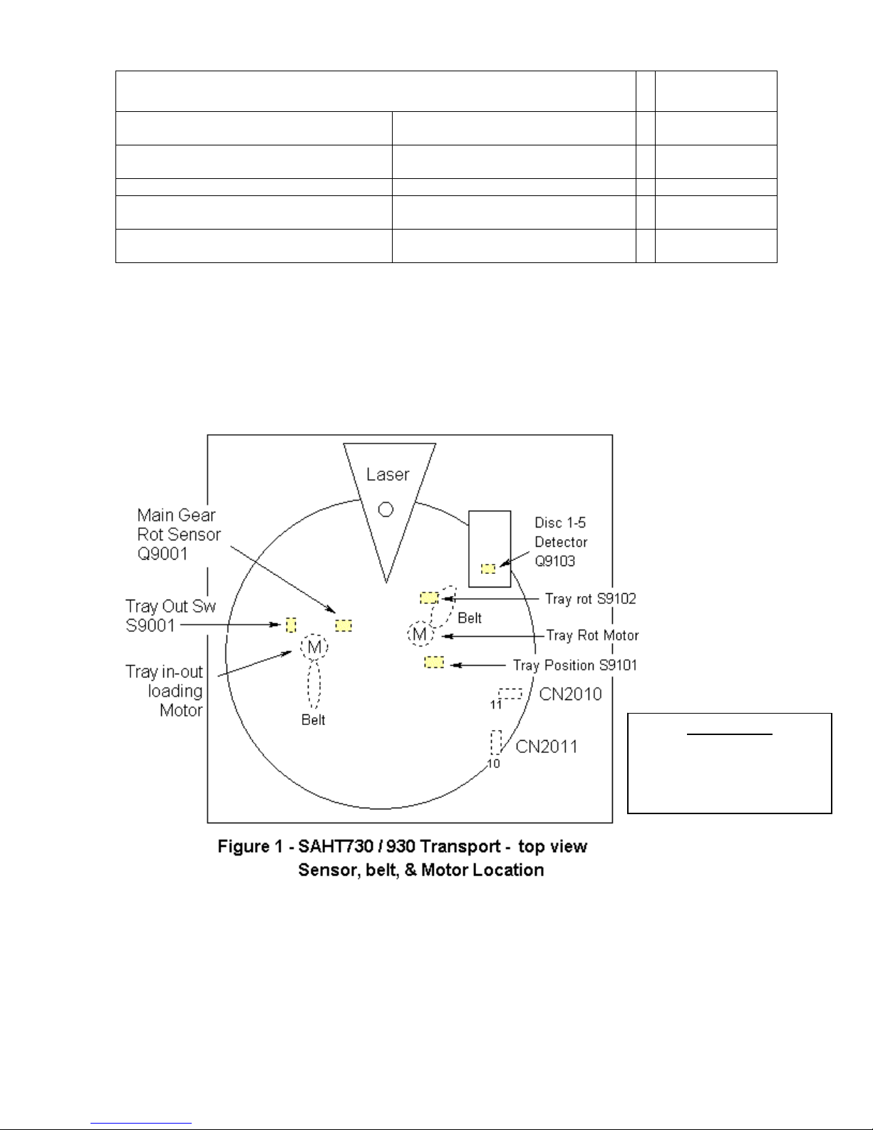
2. Sensors, belts, and motor location
Items in dotted lines are under the tray. Since many parts are under the tray, the tray
must be slid out to test the parts. This is easier than it looks. Use disassembly section
4 to access the parts shown below.
SA-HT730 / SAHT930
Part numbers
Tray Belt = RDV0073
Loading Belt = RDV0073
Loading Motor = REM0112
Tray Motor = same as above
6
Page 7

3. Simulated Failure Symptoms – quick fixes
Although sensor failures cause the following symptoms listed in table 3, the more
common failure is an internally broken ribbon cable that carries the sensor signal to
the microprocessor.
To determine which is at fault, begin testing using figures 4 and 5 or order the cable
with the corresponding sensor. For example the motors (#6 & #7 in table 3) and
S9001 (#4) can be quickly checked with an ohmmeter at the CN2010/2011 cable end
(see figures 4 or 5). If the part tests bad bypass the cable and recheck the part right
at the part’s terminal.
CN2010 ribbon cable p/n = REZ1484 (11 pins)
CN2011 ribbon cable p/n = REZ1483 (10 pins)
Simulated Failures
Sensor Cable Symptom Comments
1. Disc Det Q9103
open
2. Tray rotation Q9102
open.
3. Tray position
Q9101 open.
4. Main gear position
Q9001 open.
5. Tray out switch
S9001 open.
6. Tray Loading Motor CN2011 Front panel display = “Please Wait” or
7. Tray Rotation Motor CN2010 Front panel display = “Please Wait”
CN2010 No disc detected (no PB possible).
CN2010 Tray motor rotates back & forth for ¼ rotation then
shuts down. H01 error code shown.
CN2010 Slow continuous CCW rotation of the tray. “INIT”
appears and no buttons work except power.
CN2011 Tray moves out and spins, then the tray moves in.
and the mech clamps & then unclamps. Repeats.
CN2011 Normal start up. Pressing the open tray button
permits the tray to open but it closes
automatically.
“Open/Close”
Table 3
Unit shuts
down.
Unit does not
shutdown.
Unit does not
shutdown.
Tray will not
stay open.
Motor = 14
ohms
SA-HT730 / SAHT930
7
Page 8
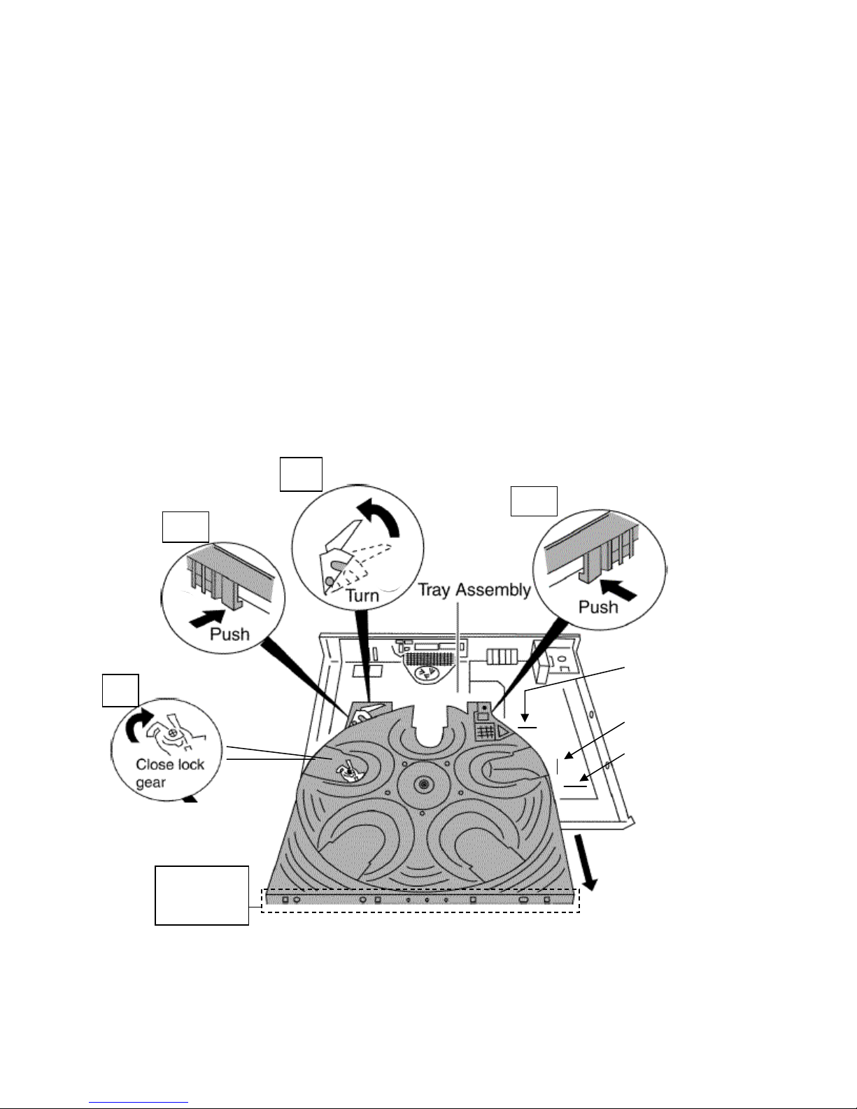
4. Tray Removal for Sensors, Belts, & Diagnostic Access
Removing the tray to access the sensors and motor first requires removing the tray
trim, and then the front panel (not shown) before the tray assembly will come out.
Follow figure 2 for easy tray removal. CAUTION – metal chassis edges are sharp.
Quick Procedure:
1. Rotate the white Close Lock Gear / lever CW (clockwise) within the turntable
platter to unlock the tray. Pull the tray forward (towards yourself) until it stops.
2. From the bottom of the black tray, remove the front silver trim piece (not
shown).
3. Unplug the two front panel cables (CN2008 & CN2009) and remove the front
panel (not shown).
4. On the main board, remove the cable (CN2010) attached to the tray.
5. Move the rear white lever counter-clockwise (CCW) as shown in figure 2 and
at the same time
6. Release the two parallel tray stops (a and b) by pressing the larger tab
(closest to you) inward toward the center of the tray (figure 2).
7. Slide the tray out towards yourself to expose the sensors, motors, and belt.
5.
6b
CN2010
Contacts = rear
CN2008
Contacts = left
CN2009
Contacts = rear
Figure 2 – Tray removal revealed
1.
6a
2. Remove
trim from
the bottom.
SA-HT730 / SAHT930
8
Page 9
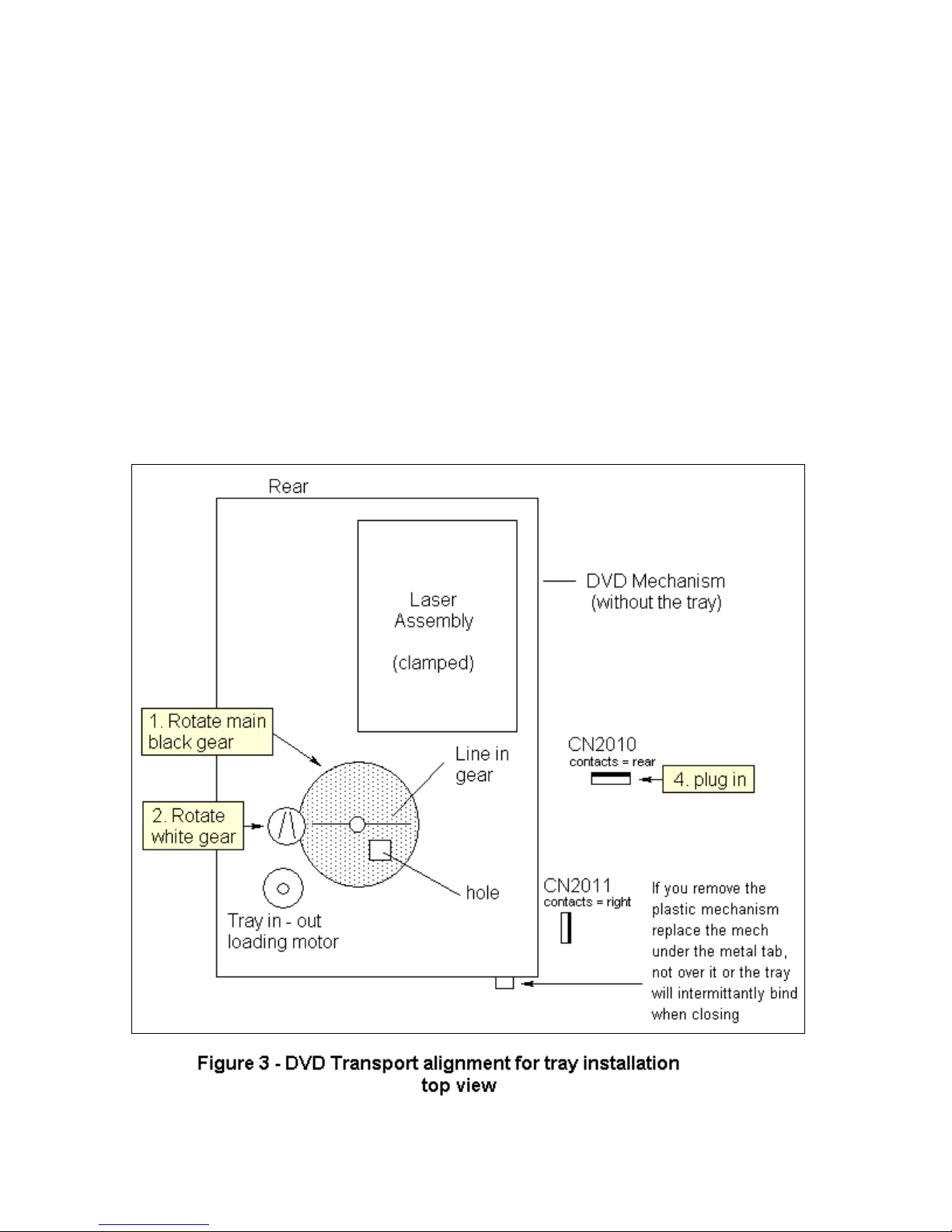
5. Tray installation (after repairs)
Refer to figure 3. Positioning the main black gear and a white gear is all that is
required to slide the tray back in.
Procedure:
1. Main black gear – Rotate the gear so that its hole is at the 5 o’clock position
and its line across the gear is horizontal as shown in figure 3. In this gear
position, the laser assembly is clamped.
2. White gear – Rotate the (now free moving) left white gear so that its top
molded in lines point towards the rear as shown.
3. Without crushing the tray’s ribbon cable, slide the tray halfway into the
mechanism.
4. Plug in the tray’s ribbon cable into CN2010. The cable’s contacts face
rearward.
5. Push the tray all the way in.
SA-HT730 / SAHT930
9
Page 10
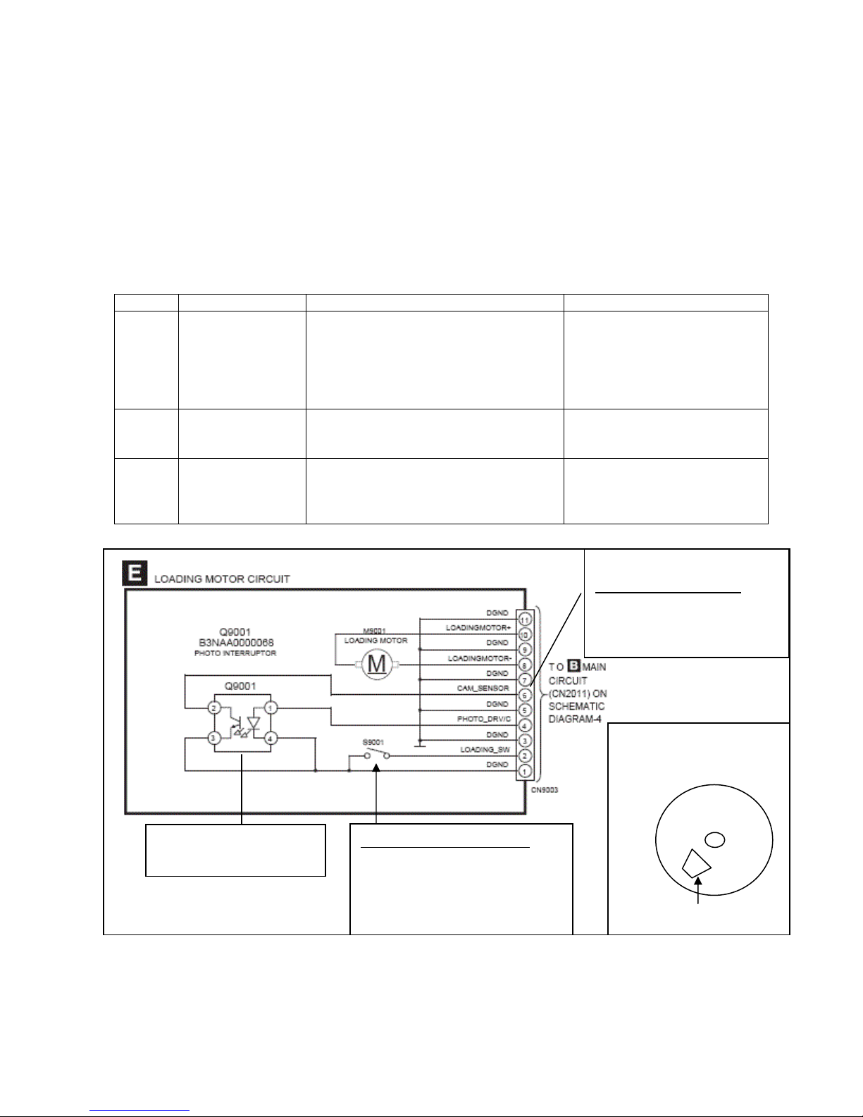
6. Sensor testing
These 7 electrical parts could cause transport problems but so can a broken
mechanical part. Test all 5 sensors and 2 motors as a group once the tray is
removed. If the parts test OK, the problem is mechanical or a ribbon cable is bad.
Testing the Tray Loading Motor and Related Sensors
With the tray removed (section 4), install the front panel to test the tray loading
operation. Plug in front panel ribbon cables CN2008 and CN2009.
Testing Parts 1/2
Part Setup Do / Watch Proof the part is good
1. Tray
in – out
loading
motor
2. Tray
out sw.
S9001
3. Main
gear
position
Q9001
1. Rotate the
main gear to the
disc clamped
position.
2. Press power
on.
Unplug the unit
from AC power.
Press the poweron button.
After laser focus searches (“INIT”), the
loading motor turns to drive the
transport to the non-clamped position
(“WAIT”). The unit will then shut down
(“H01 error”).
Measure the resistance between
CN2011 / pin 1 and pin 2.
Rotate the main gear to the position
shown in figure 4 inset so that you can
see the sensor in the cutout. Rocking
the gear changes Q9001’s logic state.
Table 4
Motor must turn belt and the
main black gear into the disc
unclamped position. Motor
resistance = 14 ohms. Motor
volts = 8Vdc. Between
CN2011/pins 8 & 10.
The switch is normally open
but shorted when pressed
(simulates tray out).
The voltage at CN2011/pin 6
will change from 0.1Vdc to
4.6Vdc as you rotate the main
gear to block Q9001’s light.
Q9001 Main gear
position sensor test
CN2011 / pin 6 =
0.1V – 4.6Vdc as gear
is rotated
Main gear position
sensor S9001
Figure 4 – Loading (Tray In – Out) Motor Circuit
SA-HT730 / SAHT930
S9001 tray in / out test
Shorted - Tray out
Open – Tray in
[Front panel displays the
words “Open” or “Close”.]
10
Inset
Main black gear position for
Q9001 sensor inspection
Cutout shows Q9001
Page 11
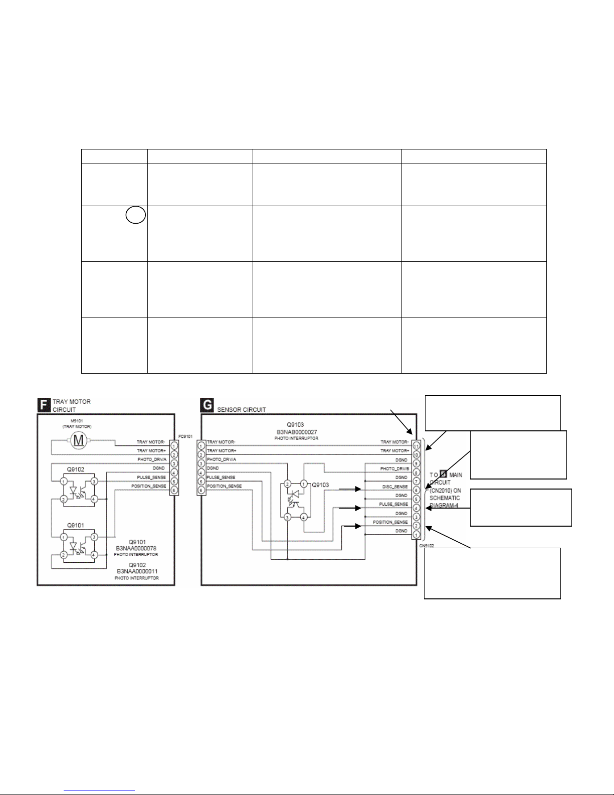
Testing the Tray Rotation Motor and Related Sensors
1. With the tray removed, install the front panel to begin the remaining tests.
2. Place the plastic tray on top of the unit between the laser block and front panel.
3. Plug the tray ribbon cable into CN2010 for testing.
Testing Parts 2/2
Part Setup Do / Watch Proof the part is good
4. Tray
rotation
motor
5. Tray
rotation
sensor
S9102
6. Tray
position
sensor
Q9101
7. Disc
presence
detector
Q9103
Press the power
on button.
Press the power
M
on button.
Press the power
on button.
Press the power
on button.
Tray motor should turn 8
seconds after the power
button is pressed.
Rotate the tray motor
gear by hand.
Before the unit shuts
down, rotate the tray past
the disc center position at
the laser assembly.
Move the tray past the
disc sensor.
Table 5
To CN2010
3.6Vdc
Power to tray motor:
Pin 11 = gnd. Pin 10 will
go from 0 – 2V – 5.6Vdc.
At CN2010/pin 4:
Voltage changes from
0.1Vdc to 4.6Vdc as the
tray gear is turned.
Volts at CN2010/pin 2:
0.15Vdc = Tray centered
for disc playback.
5Vdc. = Tray in transit.
At CN2010/pin 6:
0.3Vdc = light reflected
back from top plate.
5Vdc = light blocked
Motor: pin 11 = gnd.
Pin 10 = 0V, 2V, 5.6V
CN2010/Pin 6:
5.0V = Disc
0.3V = No Disc
Pin 4: motor rot.
0.1V to 4.6Vdc
Figure 5 – Tray Rotation circuit
SA-HT730 / SAHT930
CN2010/Pin 2:
0.15 = disc centered
5Vdc = tray bet discs.
11
Page 12
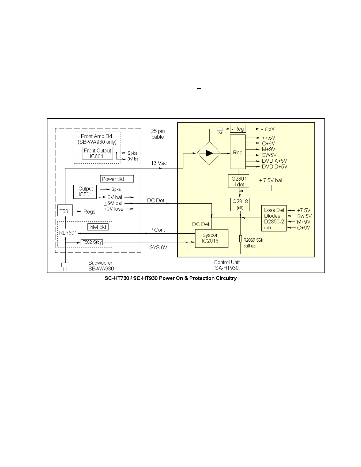
II Shutdown Problem
Protection Concept – all the shutdown possibilities
Refer to figure 6. The models SCHT730 and SCHT930 are both 2-piece units (with
speakers). The SA-HT930 / SA-HT730 control piece (figure 6, right) has no AC input.
The control unit power comes from the SB-WA 30 “Subwoofer” piece through a 25
pin umbilical cable (not shown). The subwoofer (left) houses the power output
amplifier for all 6 channels and delivers protection information to the microprocessor
(Syscon IC2018) in the control unit.
Figure 6 -
Overall Repair Strategy
Shutdown protection can be started in either the control unit (SA-HT730/HT930) or
the subwoofer (SB-WA730/WA930). Start the repair with either unit to first determine
which piece houses the problem, and then follow the individual Repair Strategy
procedure to isolate the problem.
Control Unit - In the control unit, most parts are under the board. Access to test
areas for diagnosis is overcome by using the jumper wires on the top as test points.
Since test point jumpers are used, additional diagrams and pictures are used to
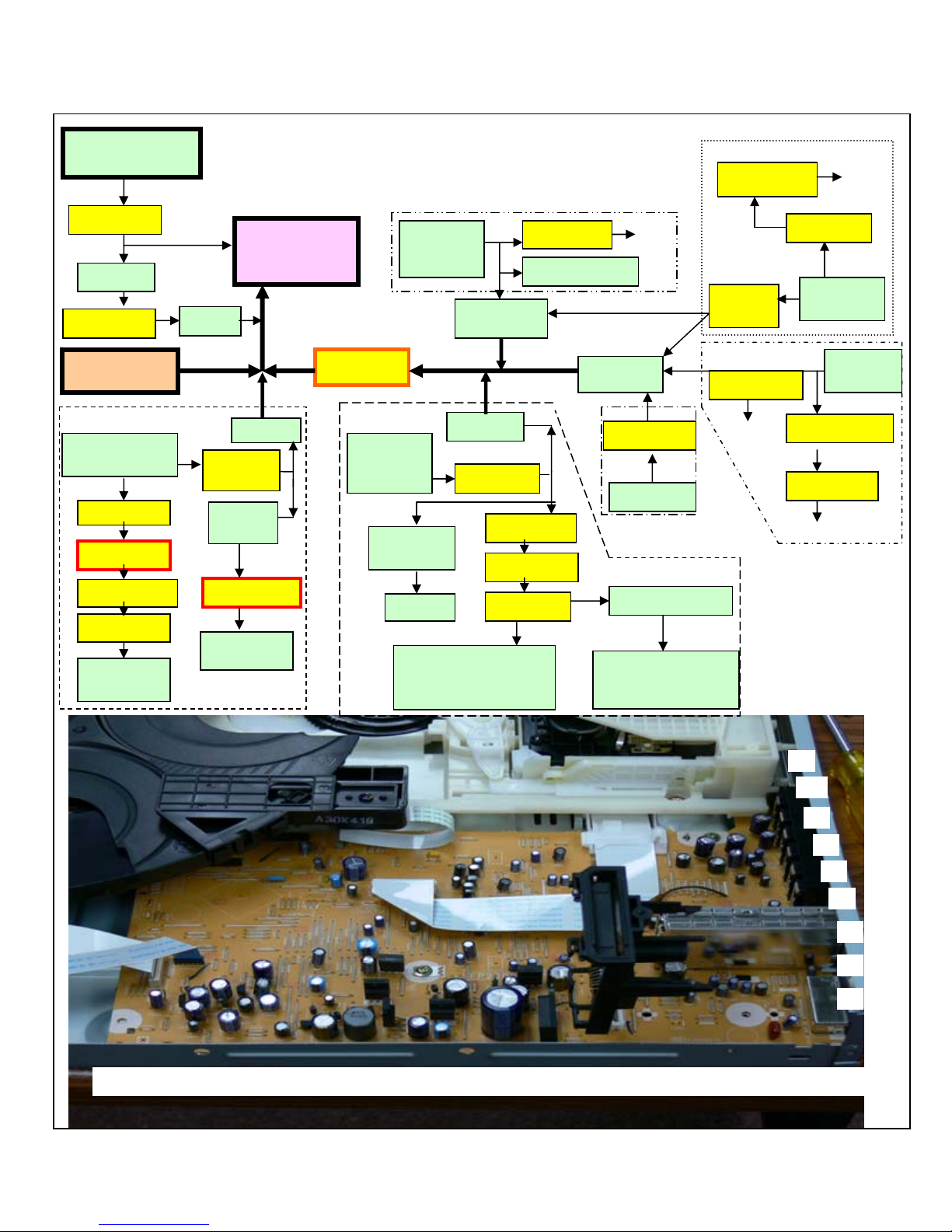
quickly locate the jumpers. The repair flow information is shown in figure 7. Control
unit repair starts on page 13.
Subwoofer Unit – All parts are accessible once the electronics is pulled from the
subwoofer speaker cabinet. Unscrewing the board from the metal frame and rotating
it 90 degrees permits operation if a ground wire is added (service position).
Subwoofer unit repair starts on page 17.
SA-HT730 / SAHT930
12
Page 13
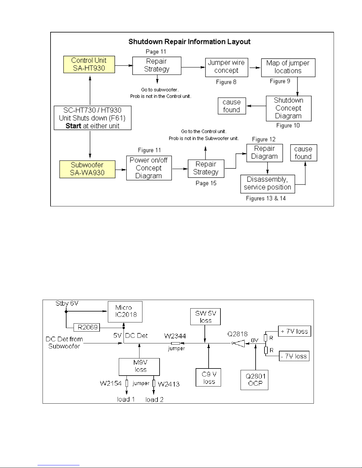
Figure 7 – Repair Information
Control Unit Repair (SA-HT730 / SA-HT930) Strategy
SC-HT730 / SC-HT930 Repair Strategy for a shutdown (F61) symptom:
These two units differ in power output so the ‘HT930 has an additional board in the
subwoofer. Troubleshooting of the control unit is almost identical for both models.
Shutdown can be either in the control unit or subwoofer.
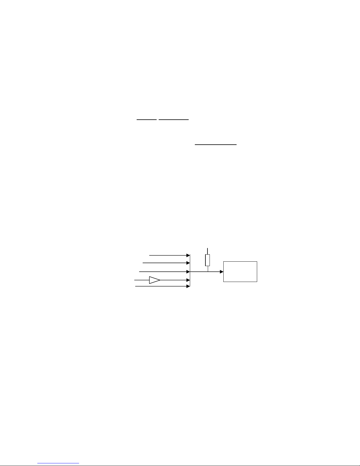
Refer to figure 8. In the control unit, diagnostic troubleshooting is quickly done from
the top of the main board by cutting jumper wires to isolate the problem. Cutting
specific jumpers on the board to stop the shutdown problem from reaching Micro
IC2018 is a fast way to determine if the problem is in the subwoofer or the control
unit. Use figure 9 to cut additional jumper wires to isolate the problem to an exact
circuit. Thereafter, repairs are done from the bottom where the parts are located.
SA-HT730 / SAHT930
Figure 8 – Cut Jumper wire Concept
13
Page 14
Control unit repair Procedure
To perform the following steps, you need to locate the jumper wires and identify
which jumpers carry what shutdown signals to the IC2018 microprocessor (using
figure 9). The purpose of the jumpers is found in the concept diagram figure 10.
Procedure:
1. First prove the problem is in the control unit by cutting the W2344 jumper on the
top of the board (at location grid K7). Measure the voltage at W2156 / G8 at
power on. This cut disconnects most of the control unit’s protection into micro
IC2018.
• If the 9Vdc is present before shutdown, the problem is in the subwoofer
assembly and not in the control unit. Reconnect the jumper and go to the repair
information on the subwoofer (page 12).
• If the 9Vdc is present, and the unit does not shutdown the problem is in the
control unit. Shut off the unit and proceed to step 2.
• If the 9Vdc is absent, the problem is in the control unit. Refer to figures 9 and
10. Either the M9V source (Q2803) is missing or the 9Vdc is loaded down
(reduced).
Cut jumpers W2413 and W2154 one at a time to determine which load causes
the reduced or missing voltage. If cutting both jumpers does not restore the
missing 9V, the M+9V source is bad.
2. If the unit does not shutdown because you have compromised the protection
circuit (e.g. cut W2344), only keep the unit on to measure a test voltage. Monitor
the various voltages at these jumpers to determine which is incorrect: [The
jumper’s grid location follows the “W” jumper number.]
W2550 / M7 = SW 5Vdc
W2417 / K8 = + 7Vdc
W2340 / I7 = - 7Vdc
W2235 / K9 = 0Vdc
Inv Q2818
W2427 / J8 = 9Vdc
3. Except for the K9 (0V) measurement, if any of the voltages listed above is
missing, cut the (load) jumper and measure each of its ends. If the voltage is now
present at one end after the cut, its load is shorted. Trace down and troubleshoot the
Use the “Protect Paths to Micro IC2018” diagram (figure 9) to make sure that the
jumper is the load jumper that bridges the load and the source voltage before cutting.
+
IC2018
Micro
SA-HT730 / SAHT930
14
Page 15
Jumper Paths to System Control IC2018 for Shutdown Problems
C2018
SYS 6 from JK2000
/ PIN 4 Subwoofer
W2145 /M6
W2541 /K6
Pin 2 of JK2000
From SUB W
M9/T9 SOURCE
D2001
Q2803 /C
W2615 /H8
W2154 / I8
W2158 /H7
W2705 / I6
CN2004
PINS 5,7
Stby 6V
Pull up
resistor
TP Jumpers (eg. W____ ) are accessible from the top of the board
W2550 /M7
CN2009 /Pin 18
W2118 /M7
W2549 /M7
W2515 /L4
)
R2069
CUT*
SYSTEM
CONTROL
I
D2850
W2156
/G8
R2707
R2708
CUT*
W2413 /E8
TUNER
DC Det
W2344 /K7
C+9
source
Q2811 /C
SW5
source
Q2813 /E
*
CN2009
PIN2
LED’S
MOTOR DRIVES
IC2007/pin 7(Tray)
IC2008/pin7(Loading
SW5 / +7
D2851
D2852
W2427 /J8
SW5V
load
Q2818
W2235 /K9
Q2801 /C
OCP
CN2010/pin8
PHOTO
INTERRUPTER
Q9103/pin1
.
W2855 / H6
W2582
/ K8
W2231 /K7
-7V load
W2417 /I7
W2340 /I7
W2854 /H6
-
+7V
load
+7 source
Q2814 /E
-7 source
Q2807/E
SA-HT730 / SAHT930
Figure 9 – Jumper Paths & Location
15
Page 16
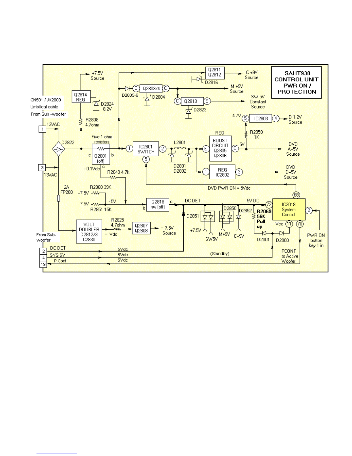
Control Unit Protection Concept
Figure 10 – Control Unit Shutdown Simplified Schematic
SA-HT730 / SAHT930
16
Page 17
Subwoofer Unit Repair (SB-WA730 / SA-WA930)
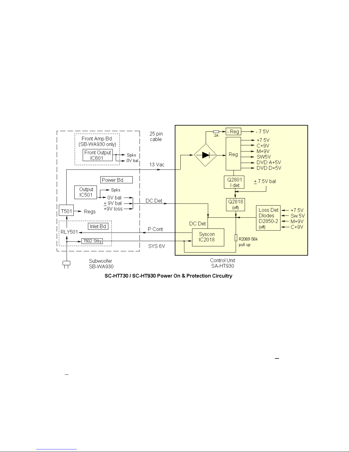
Overview - Refer to figure 11. The SC-HT930 consists of a Subwoofer and Control
unit. The units are connected by a 25 pin round umbilical cord that carries power
from the Subwoofer to the control unit and audio from the control unit back to the
subwoofer. When connected together and plugged in to AC, the Subwoofer provides
standby (SYS6V) voltage to the micro in the control unit. The SC-HT730 model is
similar but has less front channel wattage. That model does not have a Subwoofer
front Amp Board. Its front channel power amplifier is part of IC501 in the subwoofer’s
Power Board.
Figure 11 -
Protection - Refer to figure 11. The protection monitoring circuitry in both of the
subwoofer (left) and control unit (right) feed the microprocessor IC2018 in the control
unit. If shutdown is triggered, the micro via the 25 pin umbilical cable opens the
subwoofer AC relay power relay, shutting off the power for both the control &
subwoofer [but standby voltage (SYS 6V) is still present]. Error code F61 may be
displayed just before power is lost.
In the subwoofer, the lines monitored for shutdown are:
• Speaker Balance – All 6 channels to the speaker must average 0Vdc +0.6Vdc
with or without audio or the unit will shut down.
• + 9Vdc balance – Both the positive and negative 9V power supplies must be
within 1.2V of each other or the unit will shut down.
• + 9Vdc loss – Missing 9V or excessive 9V load that brings the 9V line below
5Vdc will shut down the unit.
Subwoofer Repair Strategy – Start by isolating the problem
SA-HT730 / SAHT930
17
Page 18

Follow this procedure to determine if the Subwoofer causes shut down:
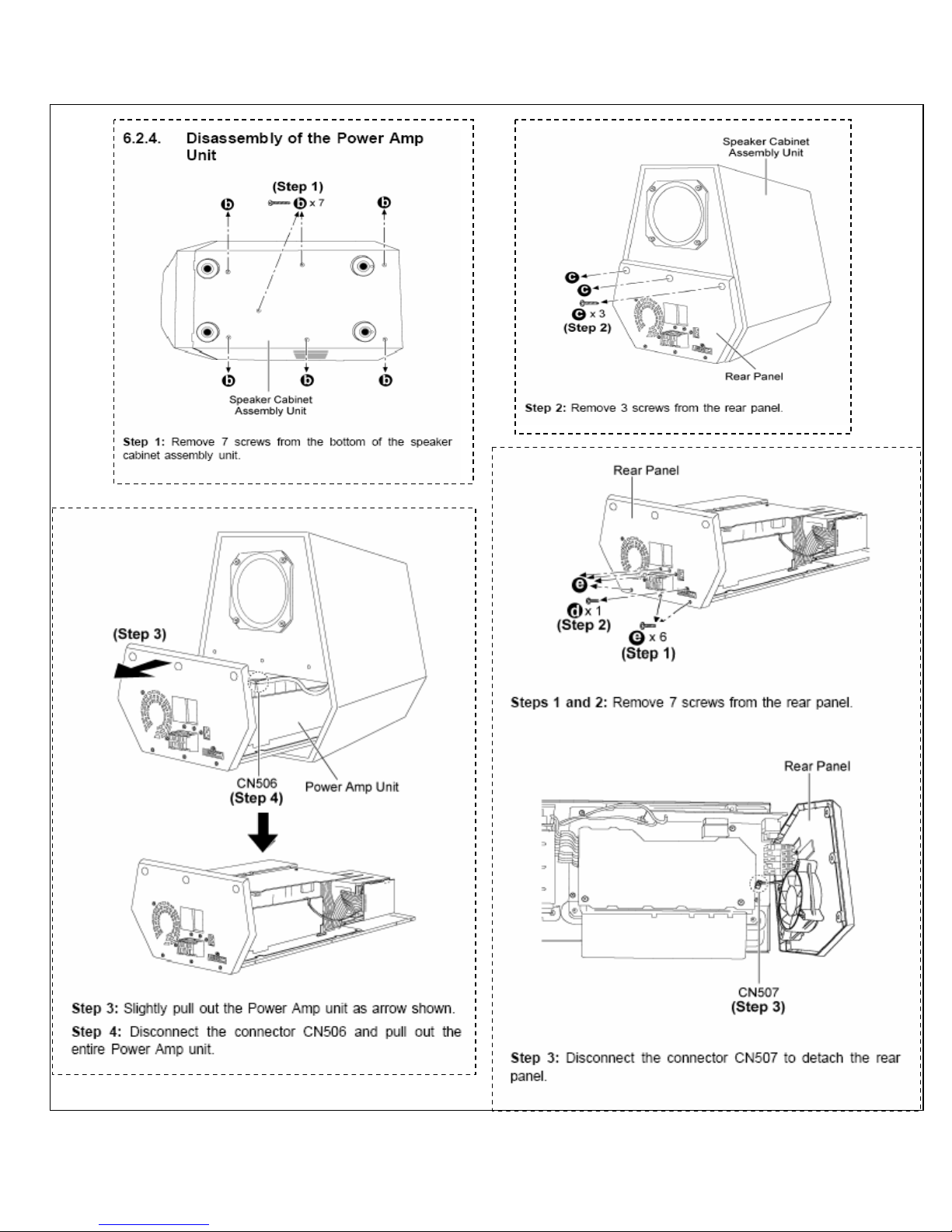
Refer to the subwoofer protection simplified troubleshooting circuit, in figure 12.
Disassembly and service positions are shown in figures 13 and 14.
3. Do not connect the Control unit to the Subwoofer. On the larger power board of
the subwoofer, tack a 10k ohm test resistor across D508 to serve as a temporary
“DC Det” pull-up resistor so that the subwoofer can be tested alone.
4. Jump the contacts of the AC relay RLY501.
5. While monitoring the unbanded anode end of D508 with your DC voltmeter,
momentarily plug the subwoofer into AC.
6. If the voltage remains at 0Vdc, unplug the AC immediately. The problem is in the
subwoofer. See subwoofer repair below.
7. If the voltage rises to 7-9Vdc, the problem is in the Control unit, not this
subwoofer. Disconnect the test resistor and close the subwoofer.
Subwoofer Repair Procedure
1. Refer to figure 12. To supply pull-up voltage, either leave the 10k ohm test
resistor across D508 or plug in the control unit, but Do not do both.
2. On the SB-WA930 Subwoofer, remove the Front Amp board. See subwoofer
disassembly diagrams figures 13 & 14.
3. If RLY501 contacts are shorted, momentarily plug the subwoofer into AC while
monitoring the unbanded anode end of D508 with your DC voltmeter. If the
control unit is connected, press its power-on button while measuring the D508/A
voltage.
• Voltage remains at 0Vdc - the problem is on the subwoofer’s power amp
board. Remove Q501/Q502, Q559, and Q556/Q557 one group at a time to
determine which group permits D508/Anode voltage to rise to 5-9V when
plugged in momentarily. If removing a group of transistors causes D508/A
voltage to rise, the feed for those transistors is at fault. E.g. If Q501/2 was
removed, and the voltage came up to 5-9V, suspect IC501 and the transistors
removed (Q501 & Q502).
• Voltage rises to 5-9Vdc (normal voltage): SB-WA930 - the problem is in the
Amp board that was unplugged or the +
unbalanced (+V not = -V). Check for open foils to connector H601 and
replace IC601 on the board. SB-WA730 – The problem is not in the
subwoofer. Check the control unit.
4. Remove the 10k ohm test resistor across D508 to prevent micro damage.
supply voltage from T501 (H601) is
SA-HT730 / SAHT930
18
Page 19
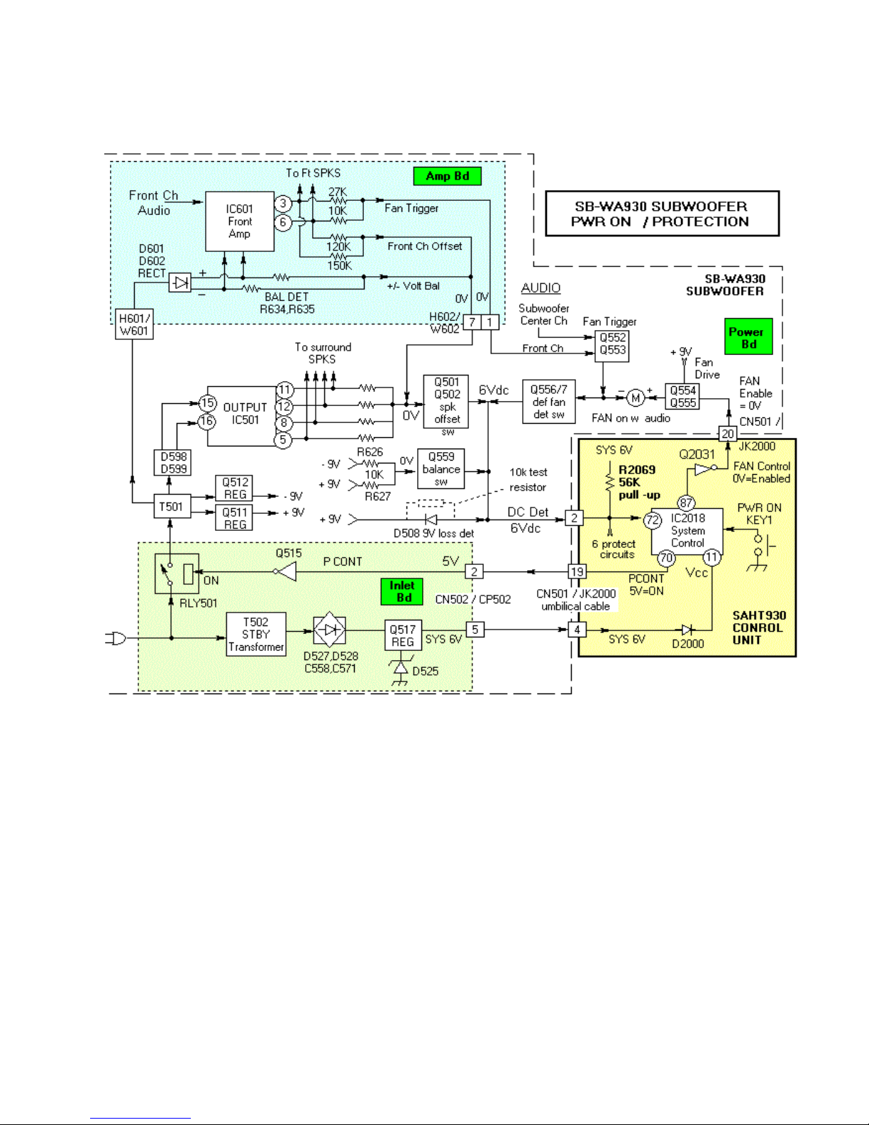
Figure 12 – Subwoofer Power On / Protection Circuit
SA-HT730 / SAHT930
19
Page 20
Subwoofer Disassembly
SA-HT730 / SAHT930
Figure 13 – Subwoofer Disassembly
20
Page 21
Subwoofer Test / Operating Position
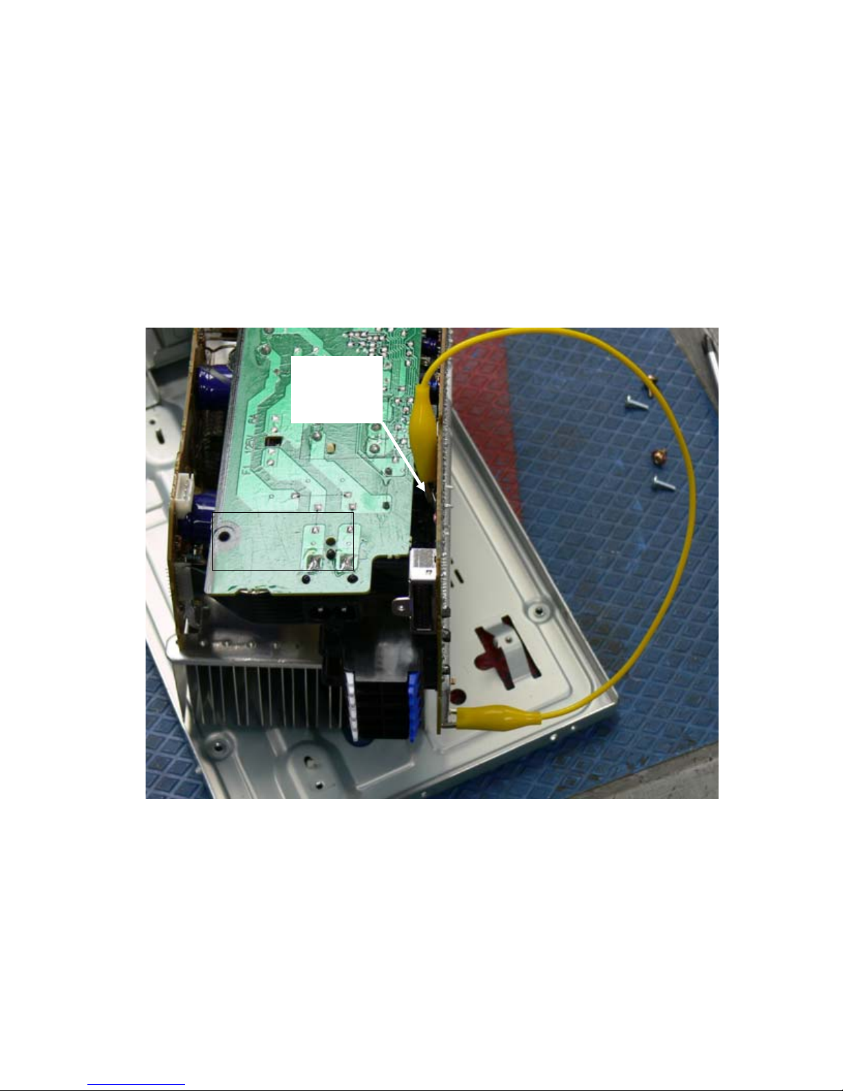
After removing the boards, the grounds must be reconnected for operation and
testing.
Procedure:
1. Remove screws to free the bottom frame from the heat sink and PC boards.
2. Rotate the assembly and rest the heat sink on the bottom frame as shown.
3. Connect the ground screw terminal to the heat sink as shown in figure 14.
4. Install the umbilical (system) cable if you are troubleshooting with the control
unit, otherwise you will tack in the 10k ohm test resistor to troubleshoot the
subwoofer independently (Subwoofer isolation procedure on page 15).
5. The subwoofer assembly is now operational and in a serviceable position.
Ground
screw
terminal
Front Bd. SBWA930 only
Figure 14 – Subwoofer Operational Service Position – SB-WA930 shown
SA-HT730 / SAHT930
21
Page 22
III “No Audio” Problems
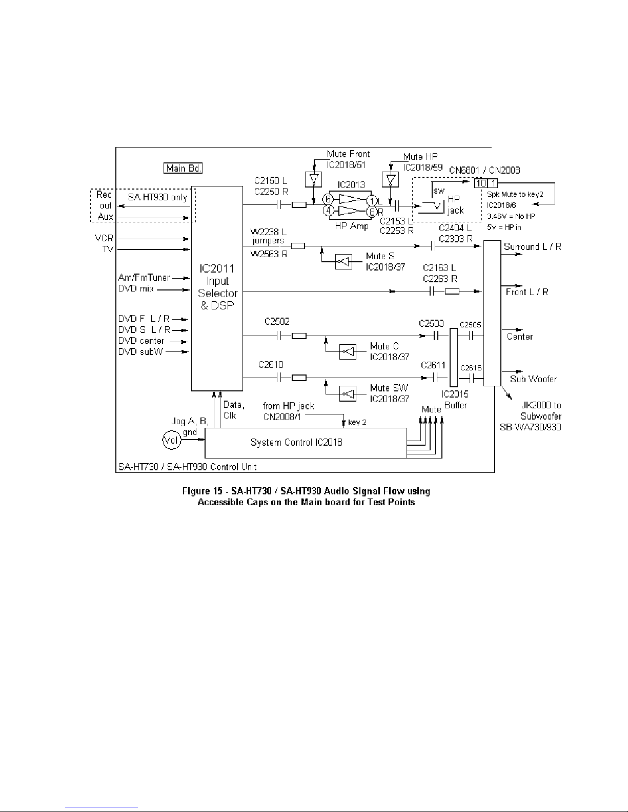
A loss of audio in one or more channels can either be caused by a break in the signal
flow or a line being muted. Use the following two diagrams to see the audio signal
flow, the mute locations, and the location of accessible capacitors in the signal path
for signal tracing.
How to trace down no audio (one or more channels)
Once an audio tone is generated (A) it can be followed through the unit (B).
A- Generating test audio to the speakers: Refer to figure 15.
Notice: When a headphone is plugged in, all the audio to the subwoofer amplifier is
muted so there is no sound from any speaker (only to the headphones).
1. TV, VCR, and FM – These stereo audio inputs produce audio from the front
and subwoofer speakers only unless the remote’s “Super Srnd” button is
pressed. Then “S.SRND” appears on the front panel and all 6 channels output
audio.
2. DVD - When playing a DVD movie with DTS or Dolby Digital (“SFC” will light in
the display and) all 6-channels will work. Older stereo-only movies (no SFC
light) will only deliver 2-channel stereo sound. When the remote’s “Super
Srnd” is pressed, the front panel display shows “Error”.
SA-HT730 / SAHT930
22
Page 23
3. Internal test tone - An alternative to input a signal to test the amplifier is to use
the internal speaker level test mode. Once in this test mode, IC2011 generates
a fixed level signal to each speaker, one at a time except the subwoofer. The
test tone lasts for approx half second at each speaker and repeats. As
feedback, the display shows which channel is test active.
Test Tone generating procedure:
a) Turn the unit on.
b) Press the front panel or remote input selector to select DVD / CD (front
panel display).
c) On the remote top opaque buttons, press DVD (so the remote buttons are
for DVD mode.
d) On the remote, press both the SHIFT and TEST buttons. The front panel
display will show the speakers that are producing the test tone.
e) Stop the test tone sequence – press ENTER or both SHIFT & TEST
buttons.
B Tracing the audio
• Audio output IC2011 can be traced by following the audio path through coupling
capacitors at the top of the main board.
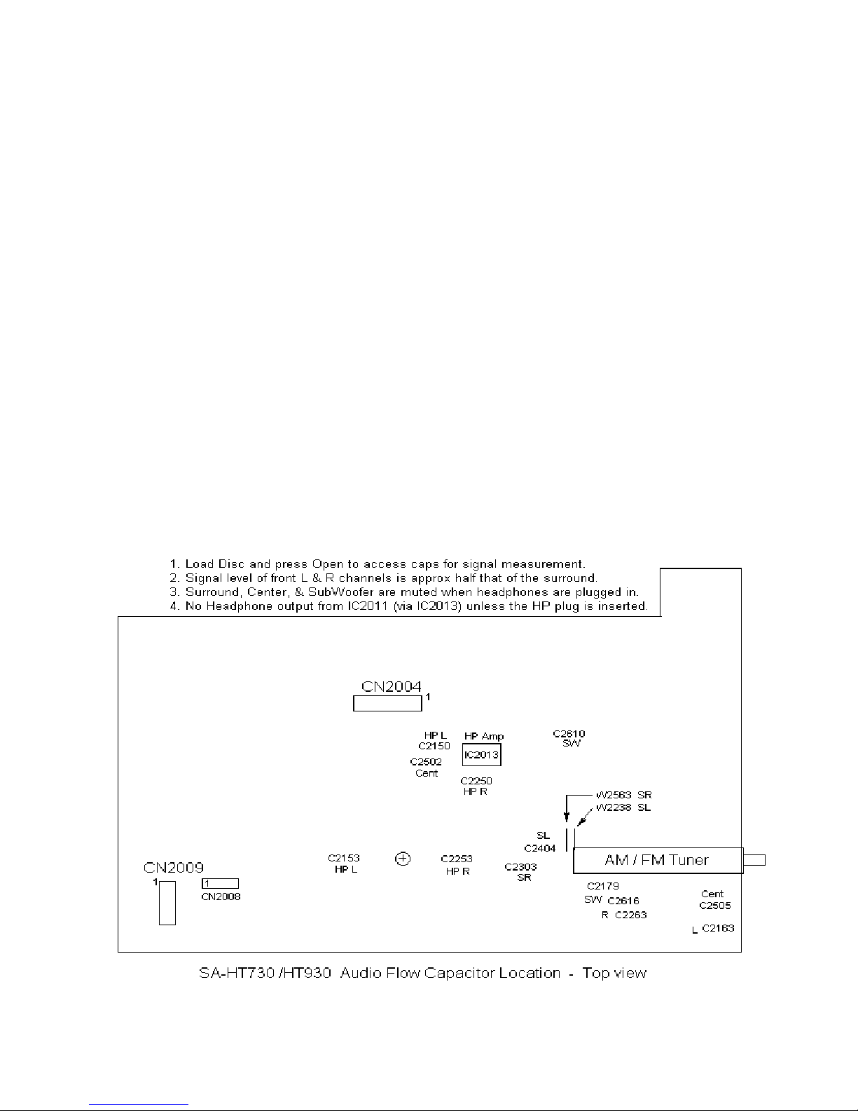
• Use figure 15 to identify the signal path and figure 16 to locate the capacitors in
the path. Follow the signal from capacitor to capacitor with a scope to determine
where the signal is lost.
Figure 16
SA-HT730 / SAHT930
23
 Loading...