

Panasonic SAPT-750-PL Service manual
A
ORDER NO. MD0706006CE
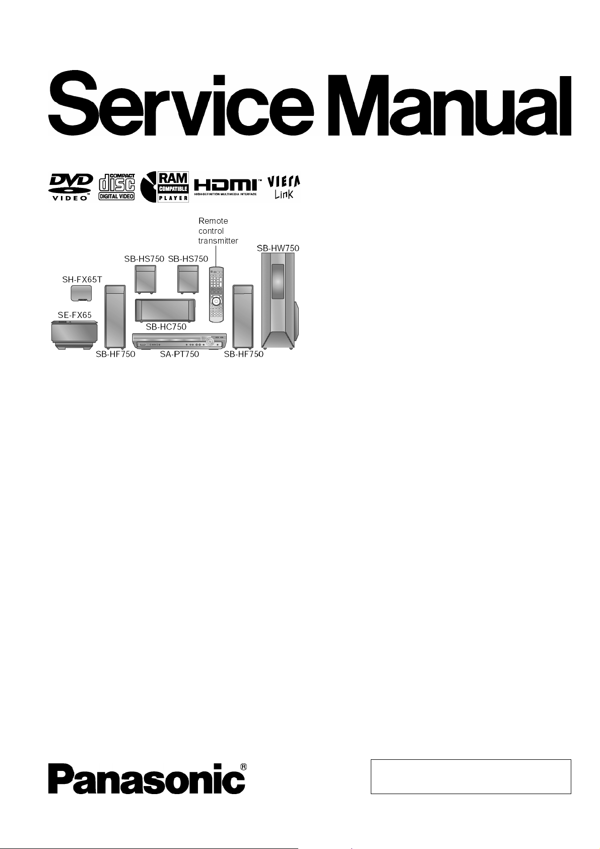
DVD Home Theater Sound System
SA-PT750PL
Colour
(K).......................Black Type
Specifications
O
OGENERAL
OO
Power Supply:
Power Consumption: 131 W
Dimensions (W×H×D): 430×75×424 mm
Mass: Main unit 5 kg
Operating Temperature Range: +5°C to +35°C
Operating Humidity Range: 5% to 90% RH (no
O
OAMPLIFIER SECTION
OO
RMS Output Power: Dolby Digital Mode
O
OTotal RMS Dolby Digital mode power:
OO
At 1 kHz and total harmonic of 10%
O
OFront Ch: 125 W / Channel (3 Ω)
OO
O
OCenter Ch: 250 W / Channel (6 Ω)
OO
O
OSurround Ch: 125 W / Channel (3 Ω)
OO
At 100 Hz and total harmonic of 10%
O
OSubwoofer Ch: 250 W / Channel (6 Ω)
OO
FTC Output Power: Dolby Digital Mode
O
OTotal FTC Dolby Digital mode power:
OO
At 120 Hz - 20 kHz and total harmonic of 1%
O
OFront Ch: 63 W / Channel (3 Ω )
OO
O
OCenter Ch: 113 W / Channel (6Ω )
OO
O
OSurround Ch: 34 W / Channel (3Ω)
OO
C 120 V, 60 Hz
condensation)
1000 W
428 W
At 45 Hz - 120 Hz and total harmonic of 1%
O
OSubwoofer Ch: 121 W / Channel (6Ω)
OO
O
OFM/AM TUNER, TERMINALS SECTION
OO
Preset Memory: FM 30 stations
AM / MW 30 stations
Frequency Modulation (FM)
Frequency range: 87.9-107.9 MHz
(200-kHz step)
87.5-108.0 MHz
(100-kHz step)
Sensitivity: 1.8 µV (IHF)
S/N 26 dB: 1.4 µV
Antenna terminals: 75 Ω (unbalanced)
Amplitude Modulation (AM/MW):
Frequency range: 520-1710 kHz (10-kHz step)
AM Sensitivity S/N 20 dB at
1000 kHz:
Phone Jack:
Terminal: Stereo, 3.5 mm jack
Music Port (Front):
Sensitivity: 100 mV, 1.2 kΩ
Terminal (Input): Stereo, 3.5 mm jack
O
ODISC SECTION
OO
Discs played [8 cm or 12 cm]:
(1) DVD (DVD-Video)
560 µV/m
© 2007 Matsushita Electric Industrial Co., Ltd. All
rights reserved. Unauthorized copying and
distribution is a violation of law.
SA-PT750PL
(2) DVD-RAM [DVD-VR, MP3 (*2, 5), JPEG (*4, 5)]
(3) DVD-R [DVD-Video, DVD-VR, MP3 (*2, 5), JPEG (*4, 5)]
(4) DVD-R DL (DVD-Video, DVD-VR)
(5) DVD-RW [DVD-Video, DVD-VR, MP3 (*2, 5), JPEG (*4, 5)]
(6) +R, +RW (Video)
(7) +R DL (Video)
(8) CD, CD-R/RW [CD-DA, Video CD, SVCD (*1), MP3 (*2, 5),
WMA (*3, 5), JPEG (*4, 5), HighMAT Level 2 (Audio and
Image)]
*1 Conforming to IEC62107
*2 MPEG-1 Layer 3, MPEG-2 Layer 3
*3 Windows Media Audio Ver.9.0 L3
ONot compatible with Multiple Bit Rate (MBR)
*4 Exif Ver 2.1 JPEG Baseline files
OPicture resolution: between 160 x 120 and 6144 x 4096
pixels (Sub sampling is 4:0:0, 4:2:0, 4:2:2 or 4:4:4).
Extremely long and narrow pictures may not be displayed.
*5 The total combined maximum number of recognizable audio
and picture contents and groups: 4000 audio and picture
contents and 400 groups
Pick Up:
Wavelength:
O
OCD: 785 nm
OO
O
ODVD: 662 nm
OO
Laser power:
O
OCD: CLASS 1M
OO
O
ODVD: CLASS 1
OO
Audio Output (Disc):
Number of channels: 5.1 ch (FL, FR, C, SL, SR,
SW)
O
OVIDEO SECTION
OO
Video System: NTSC
Composite Video Output:
O
OOutput level: 1 Vp-p (75 Ω)
OO
O
OTerminal: Pin jack (1 system)
OO
Component Video Output (480p/480i):
O
OY output level: 1 Vp-p (75 Ω)
OO
O
OPBoutput level: 0.7 Vp-p (75 Ω)
OO
O
OPRoutput level: 0.7 Vp-p (75 Ω)
OO
O
OTerminal: Pin jack (Y: green, PB: blue,
OO
P
: red) (1 system)
R
HDMI AV Output:
O
OTerminal: Type A connector (19-pin)
OO
Power Consumption in Standby Mode:
approx. 0.5 W
Note:
1. Specifications are subject to change without notice.
Mass and dimensions are approximate.
2. Total harmonic distortion is measured by the digital spectrum
analyzer.
Solder:
This model uses lead free solder (PbF).
Mechanism:
This model uses RC1U (Rotary tray) mechanism.
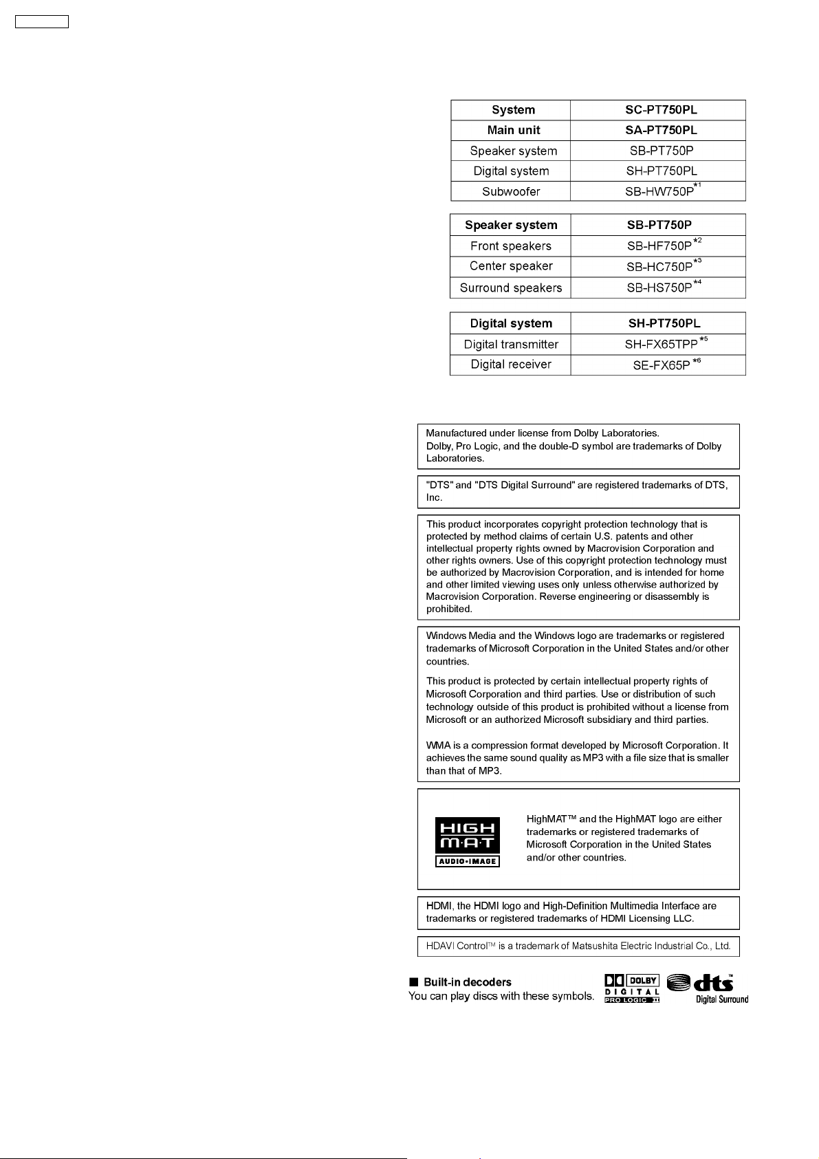
Refer to the respective original service manuals for *1, *2, *3,
*4, *5, *6.
2
SA-PT750PL
CONTENTS
Page Page
1 Safety Precautions 5
1.1. GENERAL GUIDELINES
1.2. Before Repair and Adjustment
1.3. Protection Circuitry
1.4. Safety Parts Information
2 Prevention of Electrostatic Discharge (ESD) to
Electrostatically Sensitive (ES) Devices
3 Precaution of Laser Diode
4 About Lead Free Solder (PbF)
4.1. Service caution based on legal restrictions
5 Handling Precautions for Traverse Unit
5.1. Cautions to Be Taken in Handling the Optical Pickup Unit
5.2. Grounding for electrostatic breakdown prevention
6 Accessories
7 Operation Procedures
7.1. Remote Control Key Buttons Operations
7.2. Main Unit Key Buttons Operations
7.3. Wireless Surround
7.4. Using the VIERA Link “HDAVI Control™”
7.5. Using the Music Port
7.6. Disc Information
8 New Features
8.1. About HDMI
8.2. Wireless Features
9 Self-Diagnosis and Special Mode Setting
9.1. Service Mode Summary Table
9.2. Service Mode Table (Main Unit)
9.3. Wireless Service Mode Summary Table
9.4. Service Mode Table (Wireless)
9.5. DVD Self Diagnostic Function-Error Code
9.6. Sales Demonstration Lock Function
9.7. Service Precautions
10 Assem bling and Disassemb l in g
10.1. Disassembly Flow Chart
10.2. Main Components and P.C.B. Locations
10.3. Disassembly of Top Cabinet
10.4. Disassembly of Tray Lid Assembly
10.5. Disassembly of Front Panel
10.6. Disassembly of Panel P.C.B. & Key P.C.B.
10.7. Dissassembly of Tray Base Assembly
10.8. Disassembly of Mechanism Base Assembly
10.9. Disassembly of Rear Panel
10.10. Disassembly of Wireless Adapter P.C.B.
10.11. Disassembly of Tray P.C.B.
10
10
10
12
13
13
14
15
16
17
18
20
20
22
29
29
29
39
40
42
44
45
47
49
50
51
51
51
52
52
53
53
54
54
10.12. Disassembly of D-Amp P.C.B
5
5
5
6
7
8
9
9
10.13. Disassembly of Digital Amp IC (IC5000)
10.14. Disassembly of DVD Module P.C.B.
10.15. Disassembly of Main P.C.B.
10.16. Disassembly of Regulator IC (IC2903)
10.17. Disassembly of SMPS & AC-Inlet P.C.B.
10.18. Disassembly of Switch Regulator IC (IC5701)
10.19. Disassembly of Regulator Diode (D5803)
10.20. Disassembly of Regulator Diode (D5801/D5802)
10.21. Disassembly of Regulator Diode (D5702)
10.22. Disassembly of Tray Guide (L) & Tray Guide (R)
10.23. Disassembly of Rotary Tray
10.24. Disassembly of Open Lock Gear
10.25. Disassembly of Close Lock Gear
10.26. Disassembly of Tray Motor P.C.B.
10.27. Disassembly of Sensor P.C.B.
10.28. Disassembly of Traverse Unit
10.29. Disassembly of Pulley Gear
10.30. Disassembly of Loading Motor P.C.B.
10.31. Disassembly of Drive Gear (A) & Drive Gear (B)
10.32. Disassembly of Magnet Holder, Washer, Magnet &
Clamper
10.33. Disassembly of Support Piece, Change Lever, Slide Plate
(L) & Slide Plate (R)
10.34. Disassembly of Cam Gear
10.35. Assembly of Tray Base Assembly
11 Service Fixture and Tools
12 Service Positions
12.1. Checking & Repair Panel P.C.B. & Key P.C.B.
12.2. Checking & Repair Main P.C.B.
12.3. Checking & Repair SMPS P.C.B.
12.4. Checking & Repair D-Amp P.C.B.
12.5. Checking & Repair DVD Module P.C.B.
13 Measurements and Adjustments
13.1. Service Tools and Equipment
13.2. Important points in adjustment
13.3. Storing and handling of test discs
13.4. Optical adjustment
14 Abbreviations
15 Vol tage and Waveform Chart
15.1. DVD Module P.C.B.
15.2. Main P.C.B.
15.3. D-Amp P.C.B.
15.4. SMPS P.C.B.
15.5. Panel P.C.B.
55
55
56
56
57
58
58
59
59
60
60
61
61
61
62
62
62
63
64
64
64
65
66
66
68
68
68
68
69
69
70
71
71
71
71
72
73
75
75
77
78
78
78
3

SA-PT750PL
15.6. Tray, Loading Motor, Tray Motor & Sensor P.C.B. 79
15.7. Waveform Chart
16 Illustration of IC’s, Transistors and Diodes
17 Wiring Connection Diagram
18 Block Diagram
18.1. System Control
18.2. DVD (Servo)
18.3. DVD (Video/Audio)
18.4. DVD Interface
18.5. Audio
18.6. Audio Digital Amp
18.7. Power
19 Schem atic Diagram Notes
20 Schematic Diagram
20.1. DVD Module (DV5/HDMI) Circuit
20.2. Main Circuit & Panel
20.3. D-Amp & SMPS Circuit
20.4. Tray Circuit
20.5. Key, Wireless Adapter, AC-Inlet & Loading Motor Circuit
20.6. Tray Motor, Sensor & Optical Pickup Unit Circuit
21 Prin ted Circui t Board
80
82
83
85
85
86
87
88
89
90
91
93
95
95
100
105
109
110
111
113
21.1. DVD Module P.C.B.
21.2. Main P.C.B.
21.3. Panel, Key & Wireless Adapter P.C.B.
21.4. D-Amp P.C.B.
21.5. SMPS P.C.B.
21.6. AC-Inlet, Tray, Loading Motor, Tray Motor & Sensor
P.C.B.
22 Basic Troubleshooting Guide
22.1. Basic Troubleshooting Guide for Traverse Unit (DVD
Module P.C.B)
22.2. Basic Troubleshooting Guide for HDMI AV output
23 Overa ll Block Diagra m for PT750
23.1. SC-PT750 Main Circuit Block
23.2. SC-PT750 SMPS Circuit Block
24 Terminal Function of ICs
24.1. IC2001 (C2CBYY000472): System Control IC
25 Expl od ed Views
25.1. Cabinet Parts Location
25.2. Packaging
26 Repl acement Parts List
26.1. Component Parts List
27 Schem atic Diagram for printing with letter size
113
114
115
116
117
118
119
119
120
122
122
123
124
124
125
127
129
130
131
144
4
SA-PT750PL
1 Safety Precautions
1.1. GENERAL GUIDELINES
1. When servicing, observe the original lead dress. If a short circuit is found, replace all parts which have been overheated or
damaged by the short circuit.
2. After servicing, see to it that all the protective devices such as insulation barriers, insulation papers shields are properly
installed.
3. After servicing, carry out the following leakage current checks to prevent the customer from being exposed to shock hazards.
1.1.1. LEAKAGE CURRENT COLD CHECK
1. Unplug the AC cord and connect a jumper between the two prongs on the plug.
2. Measure the resistance value, with an ohmmeter, between the jumpered AC plug and each exposed metallic cabinet part on
the equipment such as screwheads, connectors, control shafts, etc. When the exposed metallic part has a r eturn path to the
chassis, the reading should be between 1MΩ and 5.2MΩ.
When the exposed metal does not have a return path to the chassis, the reading must be
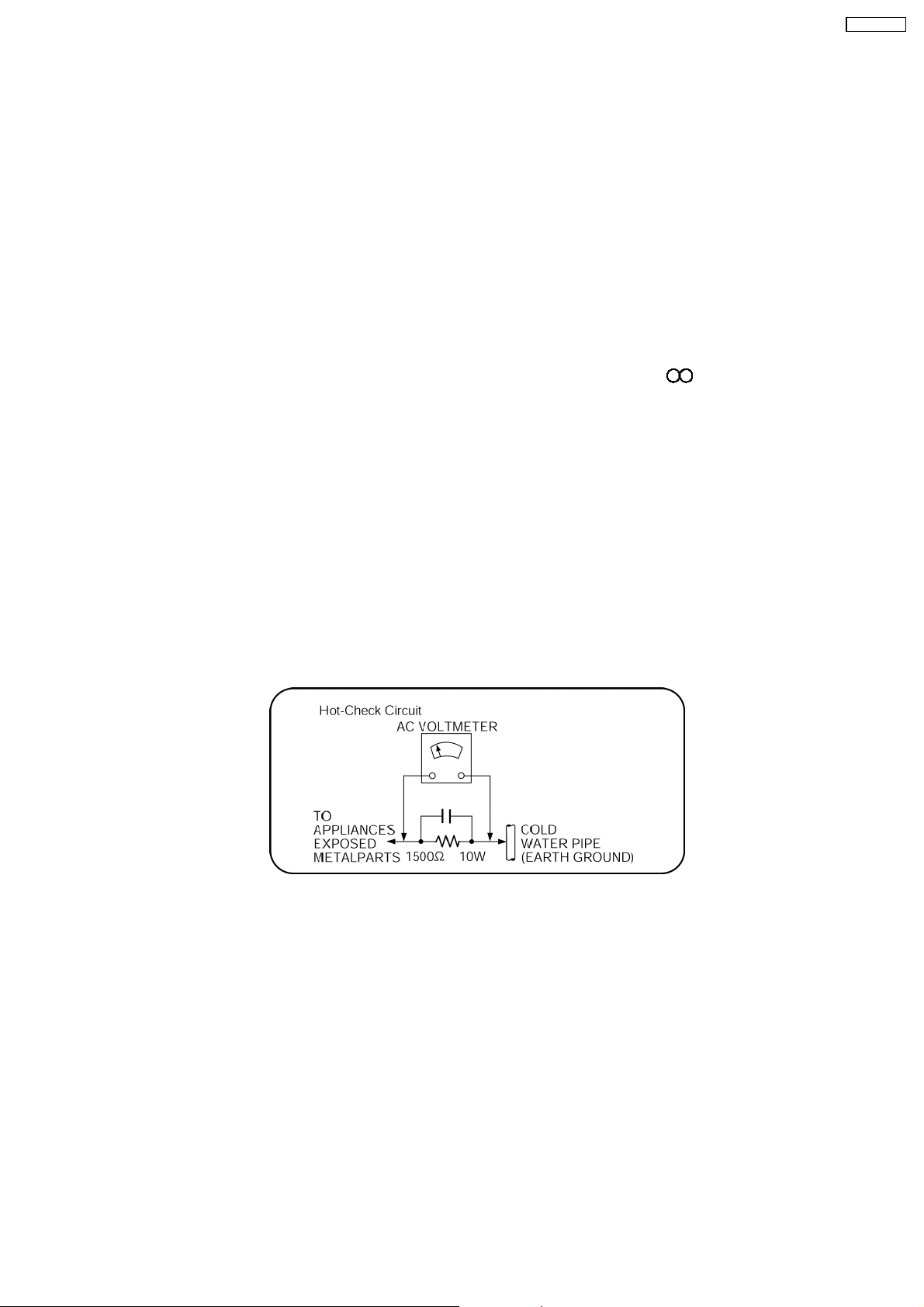
1.1.2. LEAKAGE CURRENT HOT CHECK
1. Plug the AC cord directly into the AC outlet. Do not use an isolation transformer for this check.
2. Connect a 1.5kΩ , 10 watts resistor, in parallel with a 0.15µF capacitors, between each exposed metallic part on the set and a
good earth ground such as a water pipe, as shown in Figure 1.
3. Use an AC voltmeter, with 1000 ohms/volt or more sensitivity, to measure the potential across the resistor.
4. Check each exposed metallic part, and measure the voltage at each point.
5. Reverse the AC plug in the AC outlet and repeat each of the above measurements.
6. The potential at any point should not exceed 0.75 volts RMS. A leakage current tester (Simpson Model 229 or equivalent) may
be used to make the hot checks, leakage current must not exceed 1/2 milliamp. In case a measurement is outside of the limits
specified, there is a possibility of a shock hazard, and the equipment should be repaired and rechecked before it is returned to
the customer.
Figure 1
1.2. Before Repair and Adjustment
Disconnect AC power to discharge unit AC Capacitors as such C5700, C5701, C5703, C5704, C5705 through a 10 Ω,10W
resistor to ground.
Caution:
DO NOT SHORT-CIRCUIT DIRECTLY (with a screwdriver blade, for instance), as this may destroy solid state devices.
After repairs are completed, restore power gradually using a variac, to avoid overcurrent.
Current consumption at AC 120 V, 60 Hz in NO SIGNAL mode volume minimal should be ~ 900 mA.
1.3. Protection Circuitry
The protection circuitry may have operated if either of the following conditions are noticed:
•
• No sound is heard when the power is turned on.
• •
•
• Sound stops during a performance.
• •
The function of this circuitry is to prevent circuitry damage if, for example, the positive and negative speaker connection wires are
5

SA-PT750PL
“shorted”, or if speaker systems with an impedance less than the indicated rated impedance of the amplifier are used.
If this occurs, follow the procedure outlines below:
1. Turn off the power.
2. Determine the cause of the problem and correct it.
3. Turn on the power once again after one minute.
Note:
When the protection circuitry functions, the unit will not operate unless the power is first turned off and then on again.
1.4. Safety Parts Information
Safety Parts List:
There are special components used in this equipment which are important for safety.
These parts are marked by
should be replaced with manufacturer’s specified parts to prevent shock, fire or other hazards. Do not modify the original design
without permission of manufacturer.
Reference No. Part No. Part Name & Description Remarks
342 RAE2022Z-S DT6J TRAVERSE UNIT [M]
PC5701 B3PBA0000402 PHOTO COUPLER [M]
PC5702 B3PBA0000402 PHOTO COUPLER [M]
PC5720 B3PBA0000402 PHOTO COUPLER [M]
PC5799 B3PBA0000402 PHOTO COUPLER [M]
D5701 B0FBAR000041 DIODE [M]
DZ5701 ERZV10V511CS ZENER [M]
TH5701 D4CAA5R10001 THERMISTOR [M]
TH5860 D4CC11040013 THERMISTOR [M]
L2101 J0JBC0000015 CHIP INDUCTOR [M]
L2201 J0JBC0000015 CHIP INDUCTOR [M]
L2802 J0JBC0000015 CHIP INDUCTOR [M]
L2803 J0JBC0000015 CHIP INDUCTOR [M]
L2804 J0JBC0000015 CHIP INDUCTOR [M]
L2805 J0JBC0000015 CHIP INDUCTOR [M]
L5001 G0B9R5K00003 LINE CHOKE COIL [M]
L5002 G0B9R5K00003 LINE CHOKE COIL [M]
L5201 G0B9R5K00003 LINE CHOKE COIL [M]
L5301 G0B9R5K00003 LINE CHOKE COIL [M]
L5500 J0JKB0000020 EMI BEAD CORE [M]
L5501 J0JKB0000020 EMI BEAD CORE [M]
L5702 ELF22V035B COIL [M]
L5721 J0JKB0000020 EMI BEAD CORE [M]
T2900 G4D1A0000117 TRANSFORMER [M]
T5701 ETS42BM15GAD TRANSFORMER [M]
T5751 ETS19AB236AG TRANSFORMER [M]
F1 K5D802APA008 FUSE [M]
FP2902 K5H5012A0010 FUSE PROTECTOR [M]
P5701 K2AB2B000010 JACK AC INLET [M]
A2 K2CB2CB00021 AC CORD [M]
C5700 F1BAF1020020 1000P [M]
C5701 ECQU2A334MLA 0.33 [M]
C5703 ECQU2A224MLC 0.22 [M]
C5704 F1BAF1020020 1000P [M]
C5705 F1BAF1020020 1000P [M]
in the Schematic Diagrams & Replacement Parts List. It is essential that these critical parts
Table 1
6

SA-PT750PL
2 Prevention of Electrostatic Discharge (ESD) to
Electrostatically Sensitive (ES) Devices
Some semiconductor (solid state) devices can be damaged easily by static electricity. Such components commonly are called
Electrostatically Sensitive (ES) Devices. Examples of typical ES devices are integrated circuits and some field-effect transistors and
semiconductor "chip" components. The following techniques should be used to help reduce the incidence of component damage
caused by electrostatic discharge (ESD).
1. Immediately before handling any semiconductor component or semiconductor-equipped assembly, drain off any ESD on your
body by touching a known earth ground. Alternatively, obtain and wear a commercially available discharging ESD wrist strap,
which should be removed for potential shock reasons prior to applying power to the unit under test.
2. After removing an electrical assembly equipped with ES devices, place the assembly on a conductive surface such as
aluminum foil, to prevent electrostatic charge buildup or exposure of the assembly.
3. Use only a grounded-tip soldering iron to solder or unsolder ES devices.
4. Use only an anti-static solder removal device. Some solder removal devices not classified as "anti-static (ESD protected)" can
generate electrical charge sufficient to damage ES devices.
5. Do not use freon-propelled chemicals. These can generate electrical charges sufficient to damage ES devices.
6. Do not remove a replacement ES device from its protective package until immediately before you are ready to install it. (Most
replacement ES devices are packaged with leads electrically shorted together by conductive foam, aluminum foil or comparable
conductive material).
7. Immediately before removing the protective material from the leads of a replacement ES device, touch the protective material
to the chassis or circuit assembly into which the device will be installed.
Caution:
Be sure no power is applied to the chassis or circuit, and observe all other safety precautions.
8. Minimize bodily motions when handling unpackaged replacement ES devices. (Otherwise harmless motion such as the
brushing together of your clothes fabric or the lifting of your foot from a carpeted floor can generate static electricity (ESD)
sufficient to damage an ES device).
7
SA-PT750PL
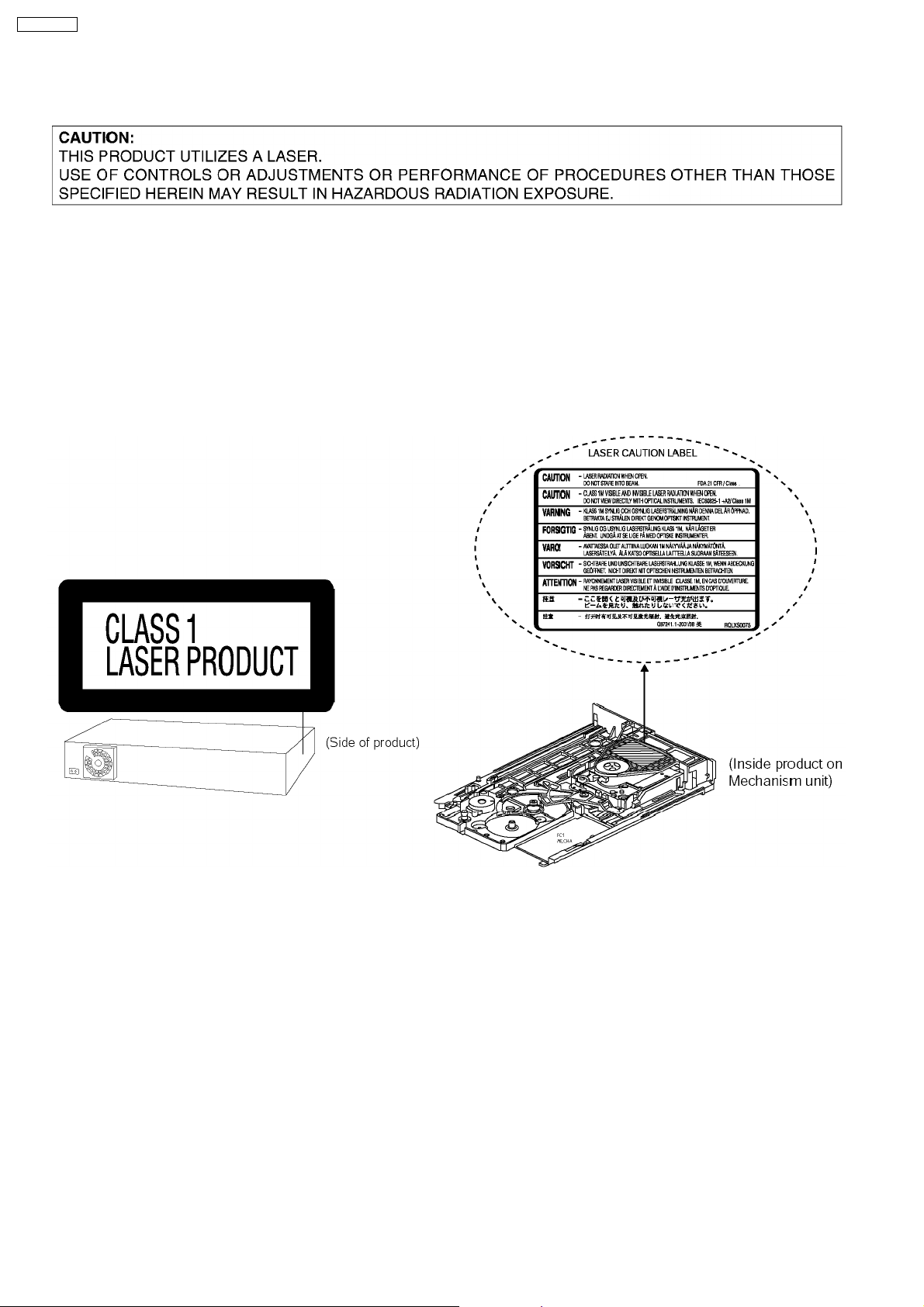
3 Precaution of Laser Diode
CAUTION :
This product utilizes a laser diode with the unit turned on, invisible laser radiation is emitted from the pickup lens.
Wavelength : 662nm/785nm
Maximum output radiation power from pickup : 100µW/VDE
Laser radiation from pickup unit is safety level, but be sure the followings:
1. Do not disassemble the pickup unit, since radiation from exposed laser diode is dangerous.
2. Do not adjust the variable resistor on the pickup unit. It was already adjusted.
3. Do not look at the focus lens using optical instruments.
4. Recommend not to look at pickup lens for a long time.
8

SA-PT750PL
4 About Lead Free Solder (PbF)
4.1. Service caution based on legal restrictions
4.1.1. General description about Lead Free Solder (PbF)
The lead free solder has been used in the mounting process of all electrical components on the printed circuit boards used for this
equipment in considering the globally environmental conservation.
The normal solder is the alloy of tin (Sn) and lead (Pb). On the other hand, the lead free solder is the alloy mainly consists of tin
(Sn), silver (Ag) and Copper (Cu), and the melting point of the lead free solder is higher approx.30 degrees C (86°F) more than that
of the normal solder.
Definition of PCB Lead Free Solder being used
The letter of “PbF” is printed either foil side or components side on the PCB using the lead free solder.
(See right figure)
Service caution for repair work using Lead Free Solder (PbF)
•
• The lead free solder has to be used when repairing the equipment for which the lead free solder is used.
• •
(Definition: The letter of “PbF” is printed on the PCB using the lead free solder.)
•
• To put lead free solder, it should be well molten and mixed with the original lead free solder.
• •
•
• Remove the remaining lead free solder on the PCB cleanly for soldering of the new IC.
• •
•
• Since the melting point of the lead free solder is higher than that of the normal lead solder, it takes the longer time to melt
• •
the lead free solder.
•
• Use the soldering iron (more than 70W) equipped with the temperature control after setting the temperature at 350±30
• •
degrees C (662±86°F).
Recommended Lead Free Solder (Service Parts Route.)
•
• The following 3 types of lead free solder are available through the service parts route.
• •
RFKZ03D01K-----------(0.3mm 100g Reel)
RFKZ06D01K-----------(0.6mm 100g Reel)
RFKZ10D01K-----------(1.0mm 100g Reel)
Note
* Ingredient: tin (Sn), 96.5%, silver (Ag) 3.0%, Copper (Cu) 0.5%, Cobalt (Co) / Germanium (Ge) 0.1 to 0.3%
9
SA-PT750PL
5 Handling Precautions for Traverse Unit
The laser diode in the optical pickup unit may break down due to static electricity of clothes or human body. Special care must be
taken avoid caution to electrostatic breakdown when servicing and handling the laser diode in the traverse unit.
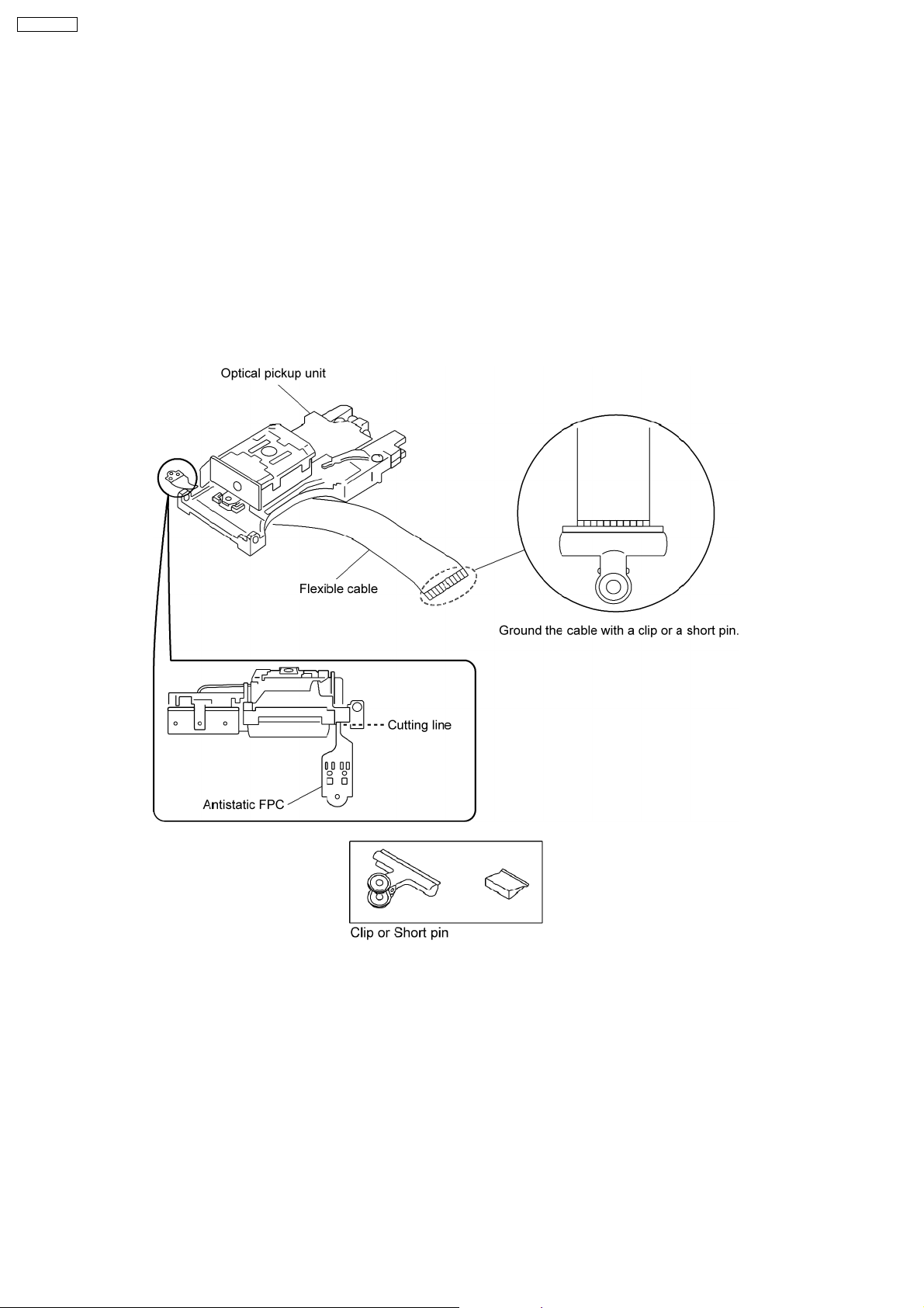
5.1. Cautions to Be Taken in Handling the Optical Pickup Unit
The laser diode in the optical pickup unit may be damaged due to electrostatic discharge generating from clothes or human body.
Special care must be taken avoid caution to electrostatic discharge damage when servicing the laser diode.
1. Do not give a considerable shock to the optical pickup unit as it has an extremely high-precise structure.
2. To prevent the laser diode from the electrostatic discharge damage, the flexible cable of the optical pickup unit removed should
be short-circuited with a short pin or a clip.
3. The flexible cable may be cut off if an excessive force is applied to it. Use caution when handling the flexible cable.
4. The antistatic FPC is connected to the new optical pickup unit. After replacing the optical pickup unitand connecting the flexible
cable, cut off the antistatic FPC.
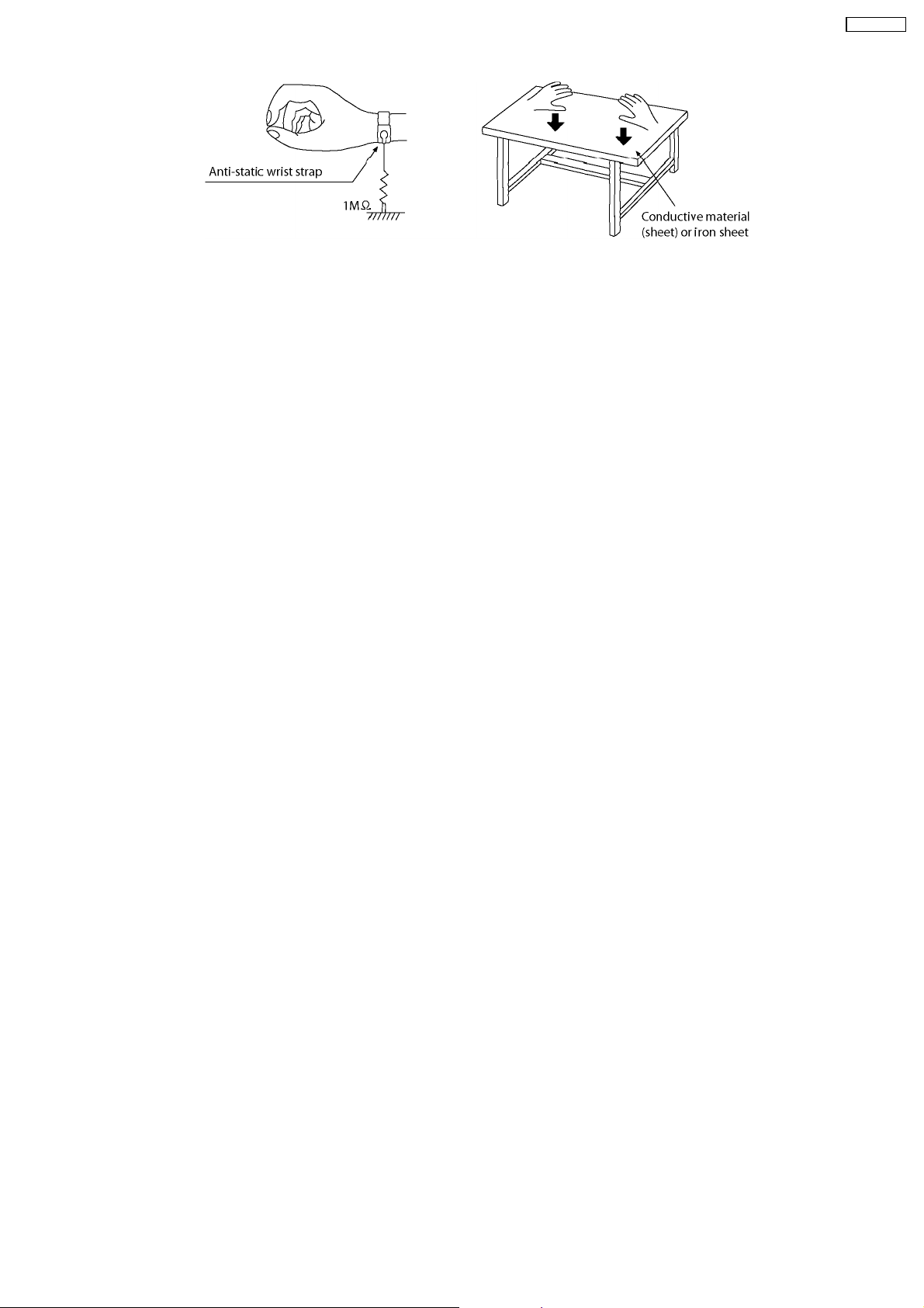
5.2. Grounding for electrostatic breakdown prevention
Some devices such as the DVD player use the optical pickup (laser diode) and the optical pickup will be damaged by static
electricity in the working environment. Proceed servicing works under the working environment where grounding works is
completed.
5.2.1. Worktable grounding
1. Put a conductive material (sheet) or iron sheet on the area where the optical pickup is placed, and ground the sheet.
5.2.2. Human body grounding
1. Use the anti-static wrist strap to discharge the static electricity form your body.
10
SA-PT750PL
11
SA-PT750PL
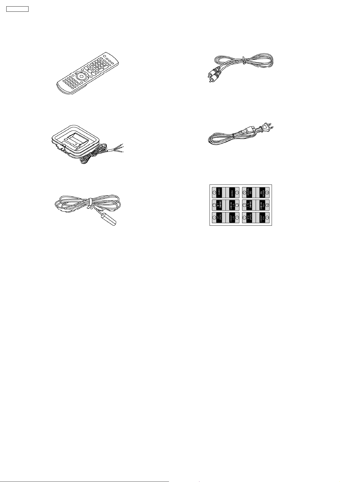
6 Accessories
•
• Note: Refer to “Replacement Parts List” (Section 26) for the part number.
• •
Remote control
AM loop antenna
Video Cable
AC cord
Antenna wire
Speaker label
12
7 Operation Procedures
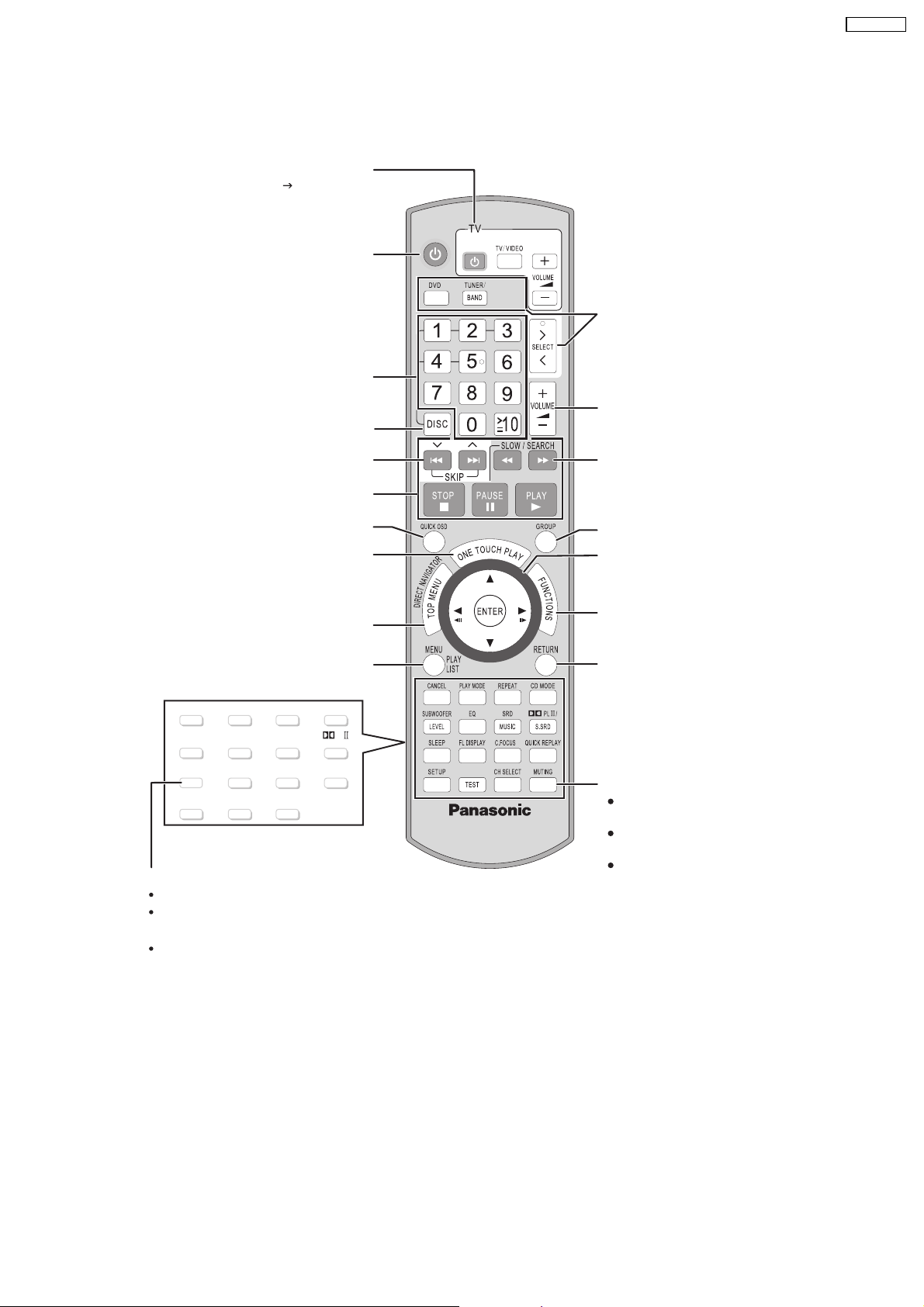
[>, < SELECT]
7.1. Remote Control Key Buttons Operations
Television operations
Refer to "Operating the television" ( OI page 10).
Turn the main unit on/off
Select disc’s title numbers etc./Enter numbers
Select the disc or show disc information
Select the source
[DVD]: DVD/CD
[TUNER/BAND]: FM/AM
[>, < SELECT]
: DVD/CD, FM/AM,
AUX, MUSIC P.
Adjust the volume of the main unit
SA-PT750PL
Select preset radio stations/channels
Basic operations for play
Display current playback condition
Start up and play a disc automatically
Show a disc top menu or program list
Show a disc menu or play list
CANCEL
SUBWOOFER
LEVEL
SLEEP
SETUP
PLAY MODE
EQ
FL DISPLAY
TEST
C.FOCUS
CH SELECT
REPEA
SRD
MUSIC
T
CD MODE
PL /
S.SRD
QUICK REPLAY
Turn the unit off automatically (Sleep timer)
The maximum setting is 120-min (in 30-min steps).
Press the button again to confirm the remaining time
on unit’s display.
To cancel, select "OFF" on the main unit’s display.
Select radio stations/channels manually
Select a group of contents to play
Frame-by-frame/Select or register menu items
on the television screen
Show on-screen menu
Return to previous screen
Mute the sound
"MUTING" flashes in the main unit’s display
while the function is on.
To cancel, press the button again or adjust
the volume.
Muting is canceled when you switch on the
unit to standby.
13
SA-PT750PL
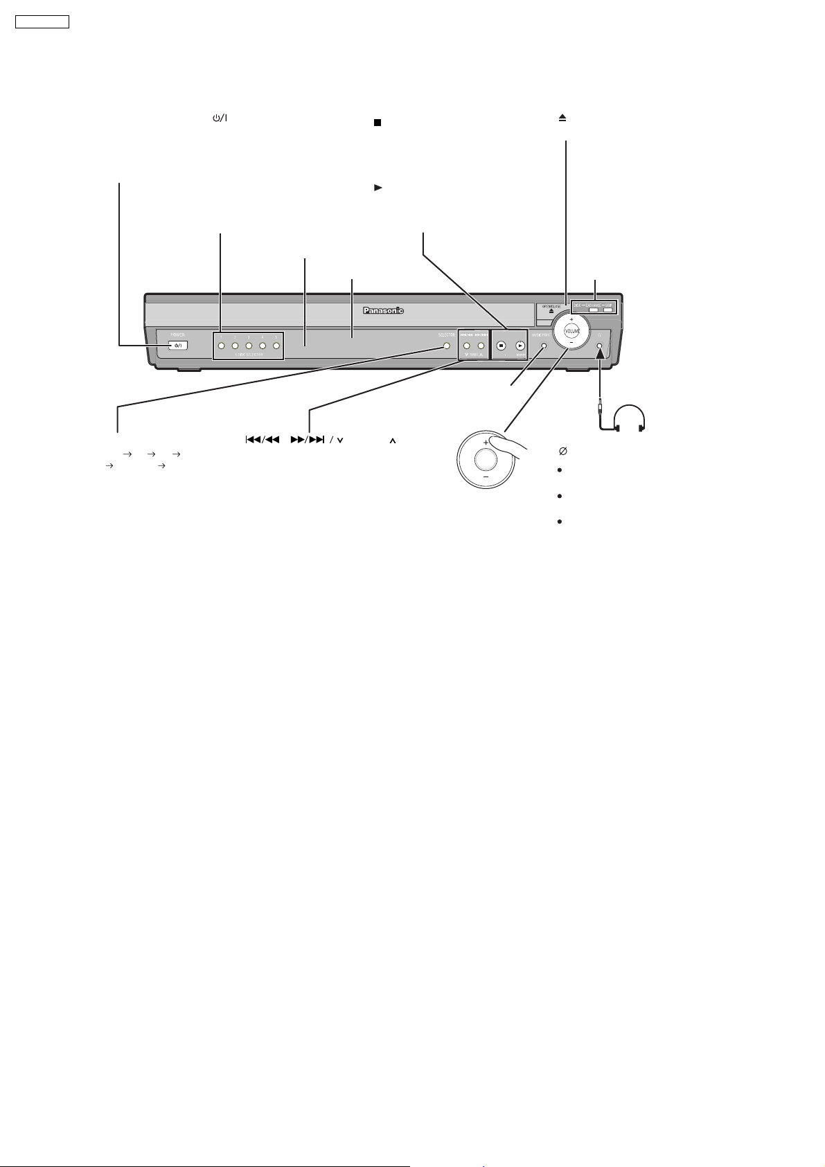
7.2. Main Unit Key Buttons Operations
Standby/on switch [POWER ]
Turn the main unit on/off.
Press to switch the unit from on to
standby mode or vice versa. In stan db y
mode, the unit is still consuming a small
amount of power.
5 DISC SELECTOR
Select a disc directly
SELECTOR
DVD/CD FM AM
AUX MUSIC P.
Return to DVD/CD
/-TUNE MODE /—FM MODE
Stop playing/
Select the tuning mode
Adjust the FM reception condition
Play discs/
Memorize the receivngi
radio stations/channels
Remote control signal sensor
Display
,
Skip or slow-search play/
Select the radio stations/channels
TUNING
/MEMORY
MUSIC PORT
Connect an external
device
VOLUME
Adjust the volume
of the main unit.
OPEN/CLOSE
Open/Close the disc drawer
DISC EXCHANGE
Open the disc drawer to
exchange the disc in the pla y
position
DISC SKIP
Skip to the next disc tray
Headphones
(not included)
Headphone plug type:
Reduce the volume before
Audio is automatically switched to
To prevent hearing damage, avoid
stereo mini plug
3.5 mm
connecting.
2-channel stereo.
listening for prolonged periods of
time.
14
7.3. Wireless Surround
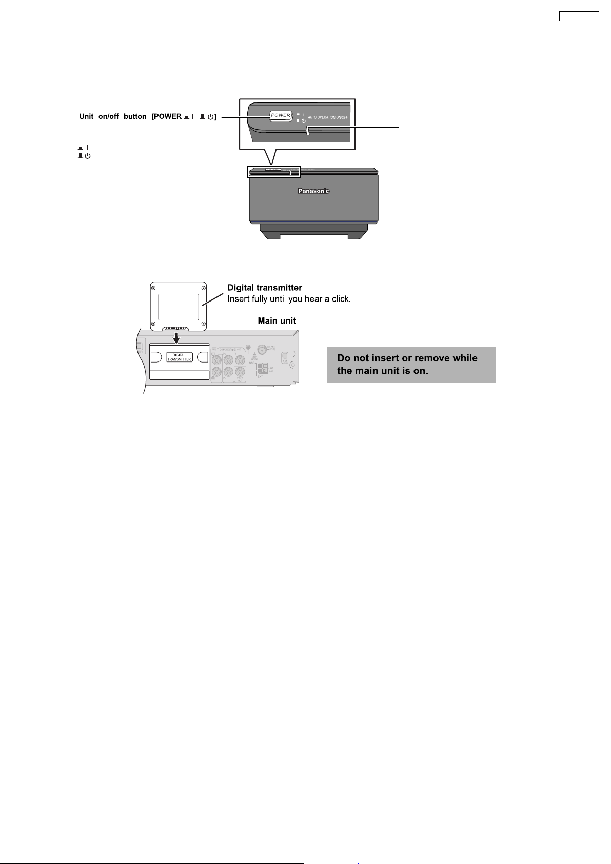
7.3.1. Wireless System Key Buttons Operations (SE-FX65)
SA-PT750PL
Use this button to turn the wireless system
on and off.
: The unit is on.
: The unit is off.
,
7.3.2. Digital Transmitter Connection (SH-FX65T)
AUTO OPERATION ON/OFF INDICATOR
The indicator lights red when the wireless
system is turned on and lights green when the
wireless link is activated.
When the wireless link is inactive for a long
time, it turns red.
15
SA-PT750PL
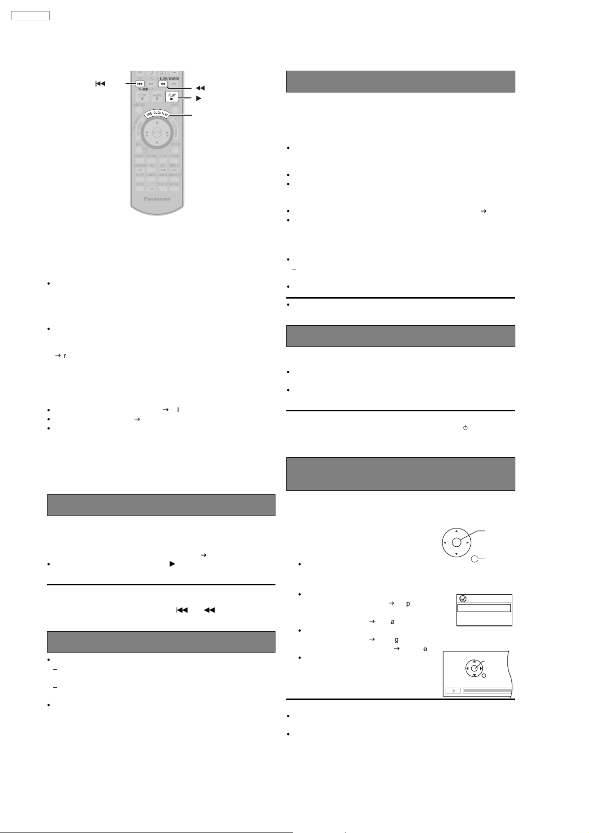
7.4. Using the VIERA Link “HDAVI Control™”
SKIP
SLOW/SEARCH
PLAY
ONE TOUCH PLAY
VIERA Link "HDAVI Control"
VIERA Link "HDAVI Control" is a convenient function that offers linked
operations of this unit, and a Panasonic television (VIERA) under "HDAVI
Control". You can use this function by connecting the equipment with the
HDMI cable. See the operating instructions for connected equipment for
operational details.
VIERA Link "HDAVI Control", based on the control functions provided by
HDMI which is an industry standard known as HDMI CEC (Consumer
Electronics Control), is a unique function that we have developed and
added. As such, its operation with other manufacturers’ equipment that
supports HDMI CEC cannot be guaranteed.
This unit supports "HDAVI Control 2" function.
The TV with "HDAVI Control 2" function enables the following operation:
VIERA Link Control only with TV s remote control (for "HDAVI Control 2")
(
g
right).
"HDAVI Control 2" is the newest standard (current as of February, 2007)
for Panasonic s HDAVI Control compatible equipment. This standard is
compatible with Panasonic s conventional HDAVI equipment.
Preparation
Confirm that the HDMI connection (gOI page 6) has been made.
Set "VIERA Link" to "Con" (gOI page 24, "HDMI" menu).
To complete and activate the connection correctly, turn on all VIERA Link
"HDAVI Control" compatible equipment and set the television to the
corresponding HDMI input mode for the home theater system.
Speaker control
You can select whether audio is output from the home theater system or
the television speakers by using the television menu settings. For details,
refer to the operating instructions of your television.
Home Cinema
Theater speakers are active.
When the home theater system is in standby mode, changing the television
speakers to theater speakers in the television menu will automatically turn
the home theater system on and select "AUX" as the source.
The television speakers are automatically muted.
You can control the volume setting using the volume or mute button on
the TV’s remote control. (The volume level is displayed on the main
unit’s FL display.)
To cancel muting, you can also use the home theater remote control ( OI page10).
If you turn off the home theater system, television speakers will be
automatically activated.
TV
Television speakers are active.
The volume of the home theater system is set to "0".
This function works only when "DVD/CD" or "AUX" is selected as the
source on the home theater system.
Audio output is 2-channel audio.
When switching between the theater and television speakers, the TV
screen may be blank for several seconds.
Power off link
When the television is turned off, the home theater system goes into
standby mode automatically.
This function works only when "DVD/CD" or "AUX" is selected as the
source on the home theater system.
When the television is turned on, the home theater system does not turn
on automatically. (Power on link is not available.)
[Note]
Only the home theater system turns off when you press [ ] for shutting it
down. Other connected equipment compatible with VIERA Link "HDAVI
Control" stays on.
Whenever the connection or settings are changed, reconfirm the points
above.
One touch play
You can turn on the home theater system and television, and start playing
the disc in the play position with a single press of a button.
Press [ONE TOUCH PLAY].
Theater speakers will be automatically activated (
This function also works if you press [ PLAY] on the home theater
remote control during home theater standby mode.
right).
[Note]
Playback may not be immediately displayed on the television. If you miss
the beginning portion of playback, press [
where playback started.
] or [ ] to go back to
Auto input switching
When you switch the television input to:
TV tuner mode, the home theater system will automatically switch to
"AUX".
HDMI input mode for the home theater system, the home theater
system will automatically switch to "DVD/CD" if it is in "AUX" mode.
When you start disc play, the television will automatically switch to the
HDMI input mode for the home theater system.
VIERA Link Control only with TV’s remote
control (for "HDAVI Control 2")
You can control the disc menus of the home theater system with the TV’s
remote control when using the "DVD/CD" source. When operating the
TV’s remote control, refer to the below illustration for operation buttons.
1 Select the theater operation menu by using
the television menu settings.
(For details, refer to the operating instructions
of your television.)
The home theater system will automatically
switch to "DVD/CD" if it is in "AUX" mode.
2 Select the desired item.
"MEN INIC IAL": Shows a disc top
"MEN ": Shows a disc menu
"Panel de control":
menu (
g
18) or program list
(
(
play list (
The basic operations
for discs are available.
OI page 15,
g
OI page19).
g
OI page15, 18) or
g
OI page 19).
[Note]
Depending on the menu, some button operations cannot be performed
from the TV’s remote control.
"Panel de control" can be selected directly by using a button on the TV’s
remote control (e.g. [OPTION]).
ENTER/
PLAY
RETURN
VIERA Link
MEN INICIAL
MEN
Panel de control
PAUSA
REPRODUCIR
OMITIROMITIR
RETROCEDER
PARAR
16
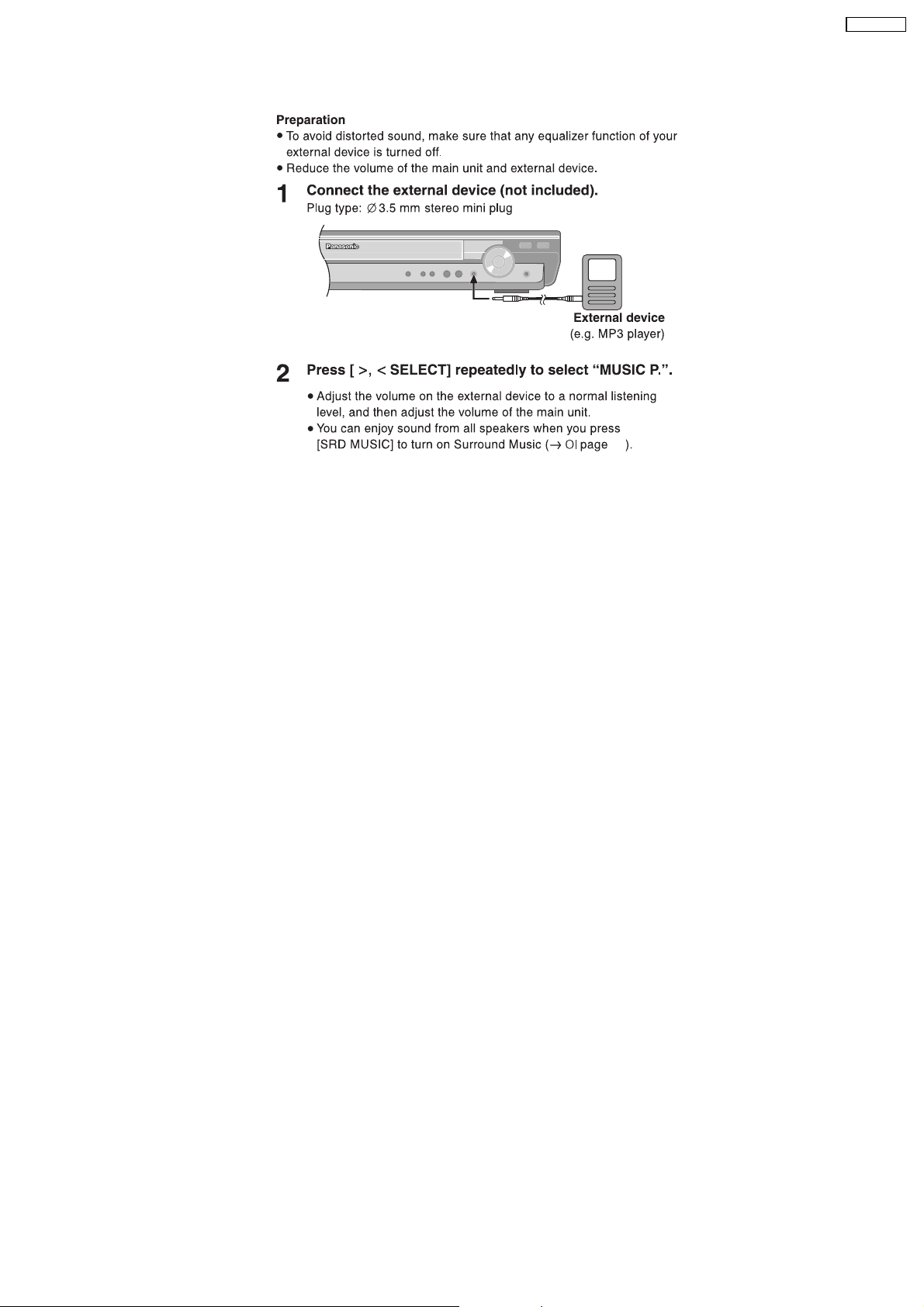
7.5. Using the Music Port
SA-PT750PL
28
17
SA-PT750PL
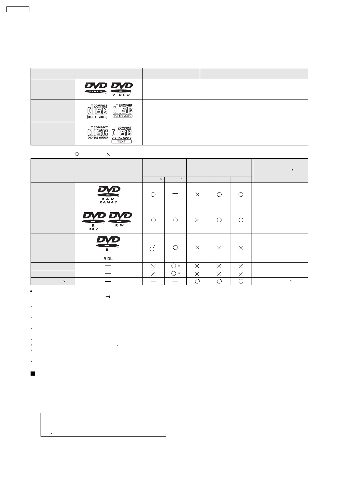
7.6. Disc Information
7.6.1. Disc Playability (Media)
Commercial discs
Disc
Logo
Indicated in these
instructions by
Remarks
DVD- Vi deo
Video CD
CD
Recorded discs ()
: Playable, : Not playable
[DVD-V]
[VCD]
[CD]
Recorded on a
Disc
Logo
DVD video
recorder, etc.
[DVD-VR]
2
[DVD-V]
4
High quality movie and music discs
Music discs with video
Including SVCD (Conforming to IEC62107)
Music discs
Recorded on a personal
computer, etc.
[WMA] [MP3] [JPEG]
DVD-RAM
DVD-R/RW
DVD-R DL
3
Finalizing
Not Necessary
Necessary
Necessary
6
+
+
R/ RW
+R DL
CD-R/RW
It may not be possible to play all the above-mentioned discs in some cases due to the type of disc, the condition of the recording, the recording
method, or how the files were created
1
This unit can play CD-R/RW recorded with CD-DA or Video CD format.
[WMA] [MP3] [JPEG] This unit also plays HighMAT discs.
2
Discs recorded on DVD video recorders or DVD video cameras, etc. using Version 1.1 of the Video Recording Format (a unified video recording
standard).
3
Discs recorded on DVD video recorders or DVD video cameras using Version 1.2 of the Video Recording Format (a unified video recording
standard).
4
Discs recorded on DVD video recorders or DVD video cameras using DVD-Video Format.
5
Recorded using a format different from DVD-Video Format, therefore some functions cannot be used.
6
A process that allows play on compatible equipment. To play a disc that is indicated as "Necessary", the disc must first be finalized on the device it
was recorded on.
7
Closing the session will also work.
1
[ Refer to Section 7.6.2. File Extension Type Support (WMA/MP3/JPEG)].
()
()
5
5
Necessary
Necessary
Necessary
7
Discs that cannot be played
DVD-RW version 1.0, DVD-Audio, DVD-ROM, CD-ROM, CDV,
CD-G, SACD, DivX Video Disc and Photo CD, DVD-RAM that
cannot be removed from their cartridge, 2.6-GB and 5.2-GB
DVD-RAM, and "Chaoji VCD" available on the market including
CVD, DVCD, and SVCD that do not conform to IEC62107.
Note about using a DualDisc
The digital audio content side of a DualDisc does not meet the
technical specifications of the Compact Disc Digital Audio
(CD-DA) format so playback may not be possible.
18
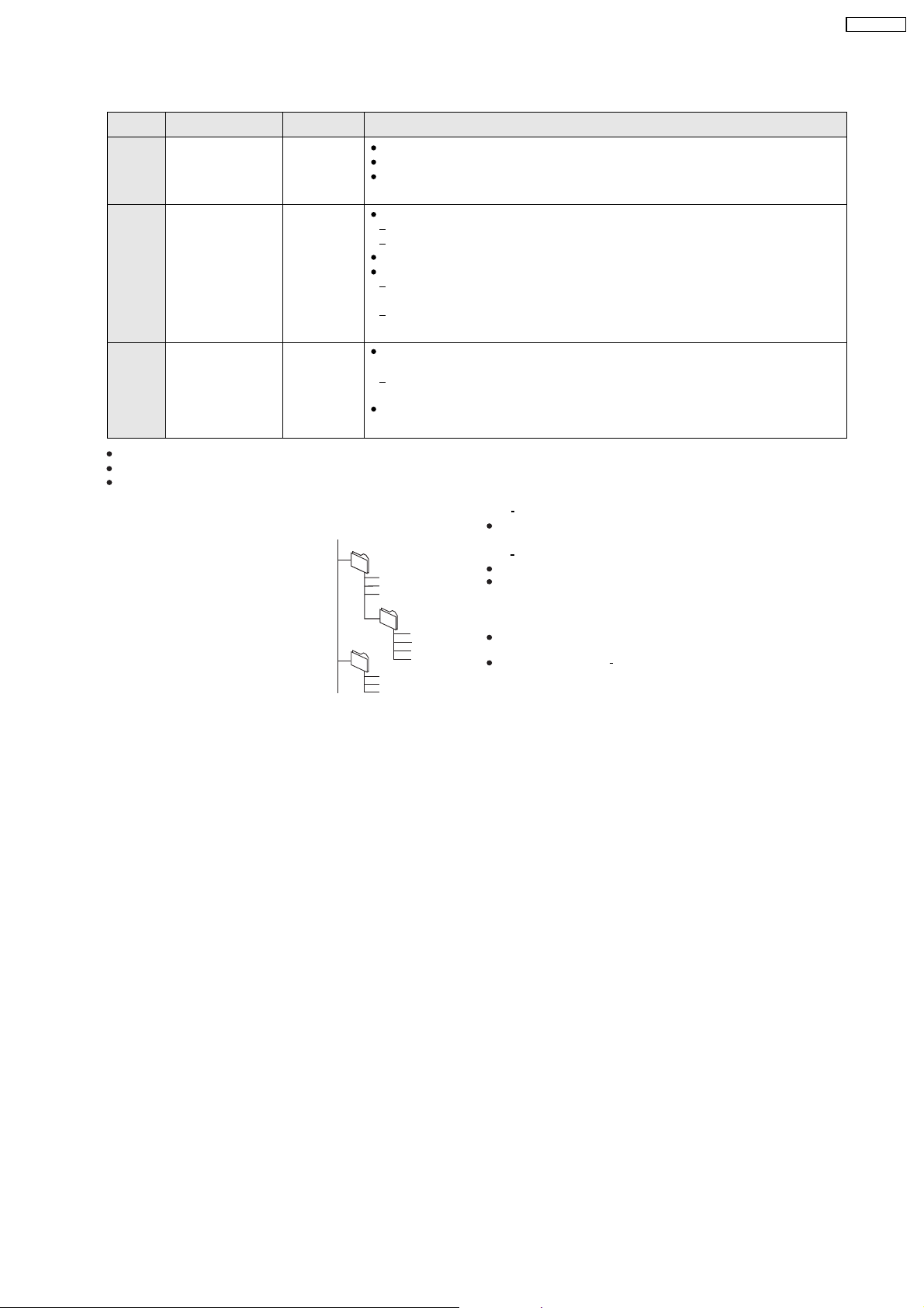
7.6.2. File Extension Type Support (WMA/MP3/JPEG)
Format Disc Extension Reference
[WMA] CD-R/RW ".WMA"
".wma"
[MP3] DVD-RAM
DVD-R/RW
".MP3"
".mp3"
CD-R/RW
[JPEG] DVD-RAM
DVD-R/RW
CD-R/RW
".JPG"
".jpg"
".JPEG"
".jpeg"
When there are more than 8 groups, the eighth group onwards will be displayed on one vertical line in the menu screen.
There may be differences in the display order on the menu screen and computer screen.
This unit cannot play files recorded using packet write.
Compatible compression rate: between 48 kbps and 320 kbps
You cannot play WMA files that are copy-protected.
This unit does not support Multiple Bit Rate (MBR: an encoding process for audio content that
produces an audio file encoded at several different bit rates).
Compatible compression rate:
between 32 kbps and 320 kbps for sampling frequencies of 32 kHz and above
between 8 kbps and 160 kbps for sampling frequencies of 24 kHz and below
This unit does not support ID3 tags.
Compatible sampling frequencies:
DVD-RAM, DVD-R/RW:
11.02, 12, 22.05, 24, 44.1 and 48 kHz
CD-R/RW:
8, 11.02, 12, 16, 22.05, 24, 32, 44.1 and 48 kHz
JPEG files taken on a digital camera that conform to DCF Standard (Design rule for Camera
File system) Version 1.0 are displayed.
Files that have been altered, edited or saved with computer picture editing software may not
be displayed.
This unit cannot display moving pictures, MOTION JPEG and other such formats, still pictures
other than JPEG (e.g. TIFF), or play pictures with attached audio.
SA-PT750PL
Naming folders and files
(Files are treated as contents and
folders are treated as groups on this
unit.)
At the time of recording, prefix folder and
file names. This should be with numbers
that have an equal number of digits, and
should be done in the order you want to
play them (this may not work at times).
e.g.
root
[MP3]
001 group
001
003 group
001 track.mp3
002 track.mp3
003 track.mp3
002 group
001 track.mp3
002 track.mp3
003 track.mp3
004 track.mp3
001 track.mp3
002 track.mp3
003 track.mp3
DVD RAM
Discs must conform to UDF 2.0.
DVD R/RW
Discs must conform to UDF bridge (UDF 1.02/ISO9660).
This unit does not support multi-session. Only the default session is
played.
CD-R/RW
Discs must conform to ISO9660 level 1 or 2 (except for extended
formats).
This unit supports multi session but if there are many sessions it takes
more time for play to start. Keep the number of sessions to a minimum
to avoid this.
19
SA-PT750PL
8 New Features
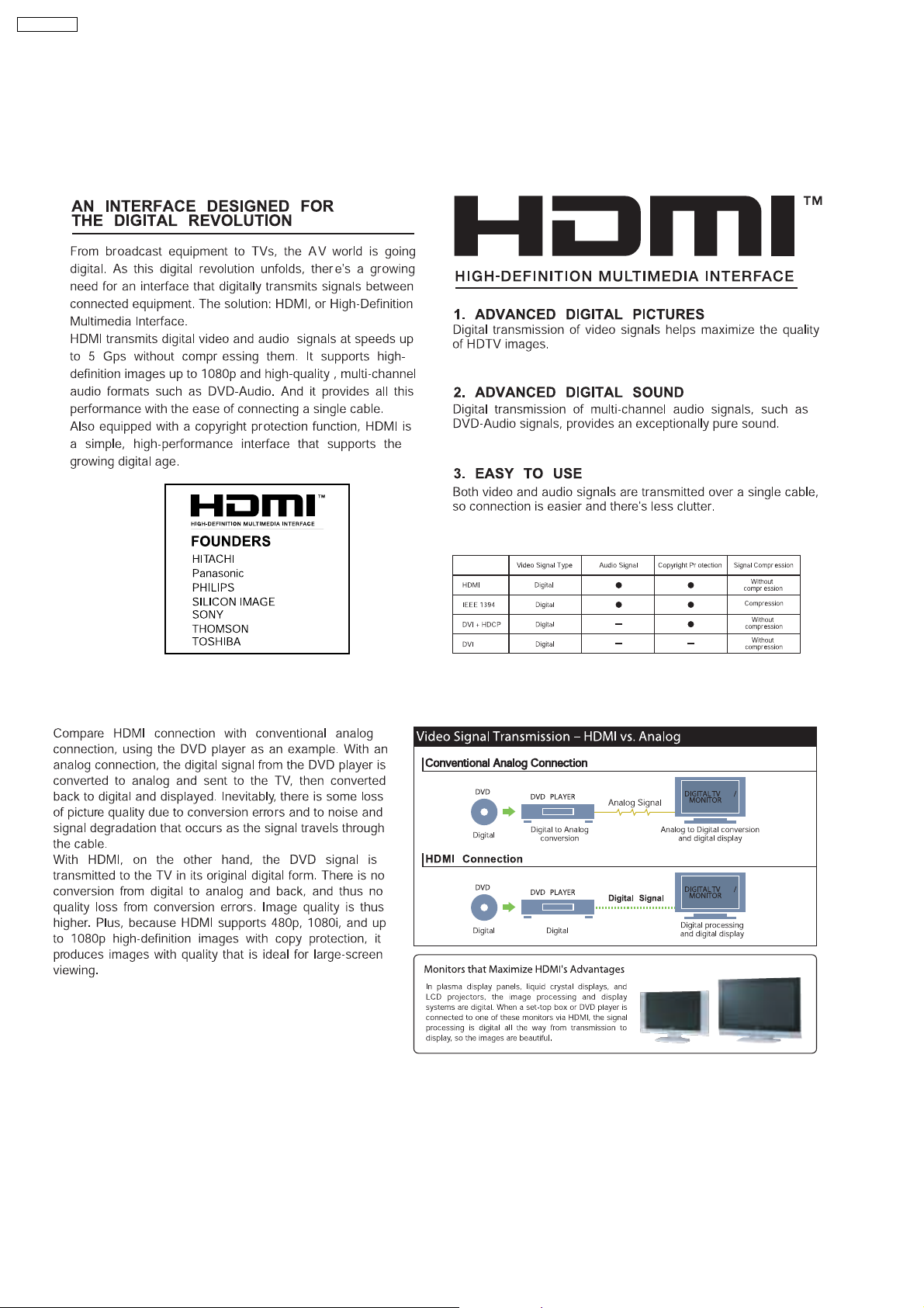
8.1. About HDMI
8.1.1. What is HDMI?
8.1.2. Advanced Digital Pictures
20
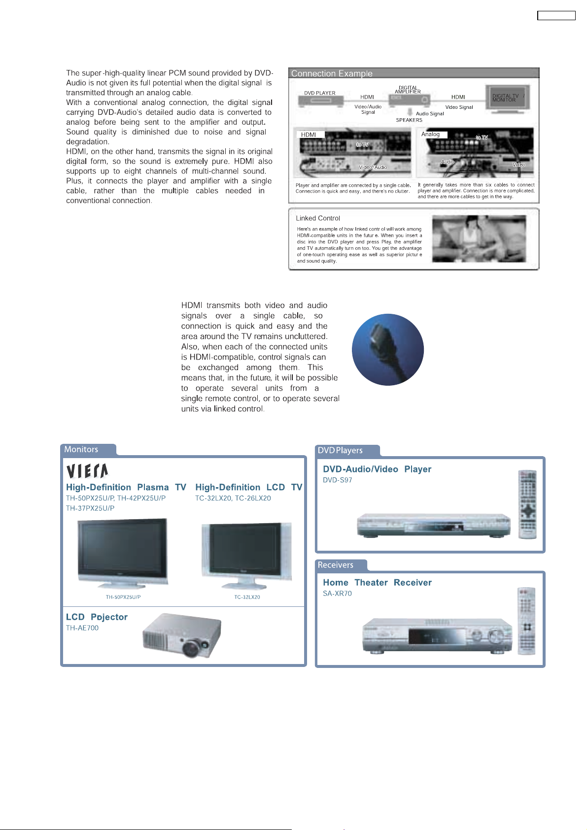
8.1.3. Advanced Digital Sound
8.1.4. Easy to Use
SA-PT750PL
8.1.5. HDMI Compatible Products
21

SA-PT750PL
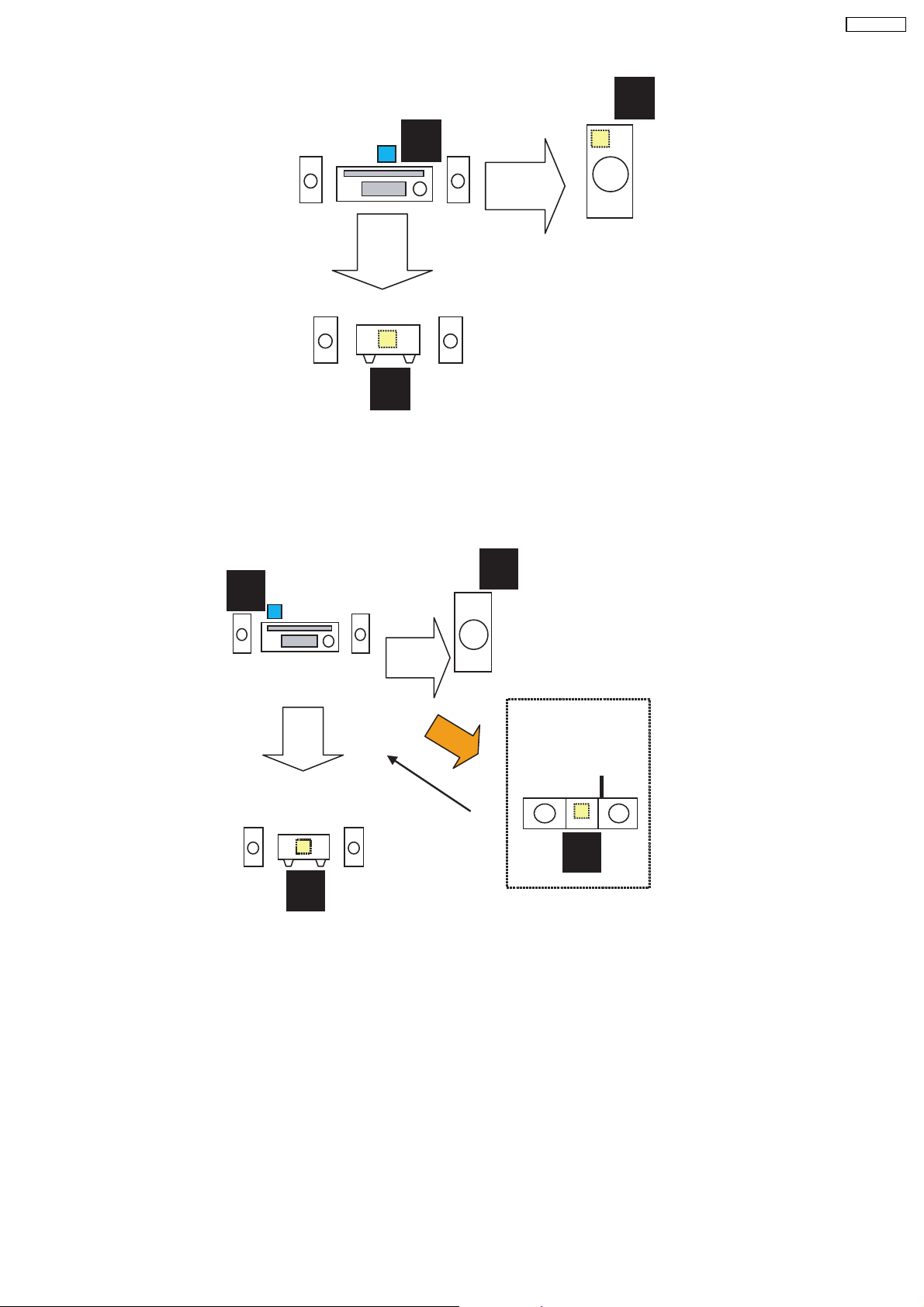
8.2. Wireless Features
8.2.1. Function Overview
Year 2007 PT models support wireless which includes FX65/FX66, wireless subwoofer and FX85 as described below:-
8.2.1.1. FX65/FX66
•
• The FX65/FX66 supports one-way wireless transmission only, that is, it will only transmit wireless audio signal to the rear
• •
surround speakers. The FX65/FX66 receiver module includes a D-AMP and SMPS. The transmitter interfaces with the main unit
using serial communications to communicate information such as mute command request, link detection and ID setting request.
Maximum range attainable is 15 meters.
8.2.1.2. Wireless Subwoofer (For PT1050 Only)
•
• The wireless subwoofer receiver module is similar in operation with FX65/FX66 in such a way that it only supports one-way
• •
wireless transmission. It also includes a D-AMP and SMPS. The difference in the wireless subwoofer receiver module is the way
its hardware interprets the audio it receives from the transmitter since it is the same audio received by the FX65/FX66 receiver.
Maximum range attainable is 30 meters.
8.2.1.3. FX85
•
• The FX85 supports the multi-room function wherein it operates as a second room wireless receiver (up to a maximum of two).
• •
Maximum range attainable is 30 meters. It can send commands to the main unit to control functions such as Play, Stop,
Forward Skip/Channel Up, Reverse Skip/Channel Down. It also has a built-in DAP pocket for stand-alone operation by inserting
a DAP device (e.g. iPod) in the DAP pocket to play the device only via the device’s own control buttons, FX85 cannot control
the device using its own buttons. The transmitter interfaces with the main unit using serial communications to communicate
information such as mute command request, link detection, ID setting request and button commands from the FX85 buttons
(Play, Stop, Forward Skip/Channel Up, Reverse Skip/Channel Down). The FX85 receiver module has the following
functions/terminals/buttons:
FX85 BUTTONS FX85 FUNCTIONS
FX 85 Power Button D-Amp
Selector Button SMPS
Play Button D-Port Connector
Stop Button ID Set Switch
Forward Skip/Channel Up MPort
Reverse Skip/Channel Down
Volume Control
22
8.2.2. Block Diagram
•
• There are two types of transmitter cards, Type A and Type B, and two types of receiver modules, Type 1 and Type 2 for the
• •
wireless configuration. The block diagrams below describe the differences of each of the types.
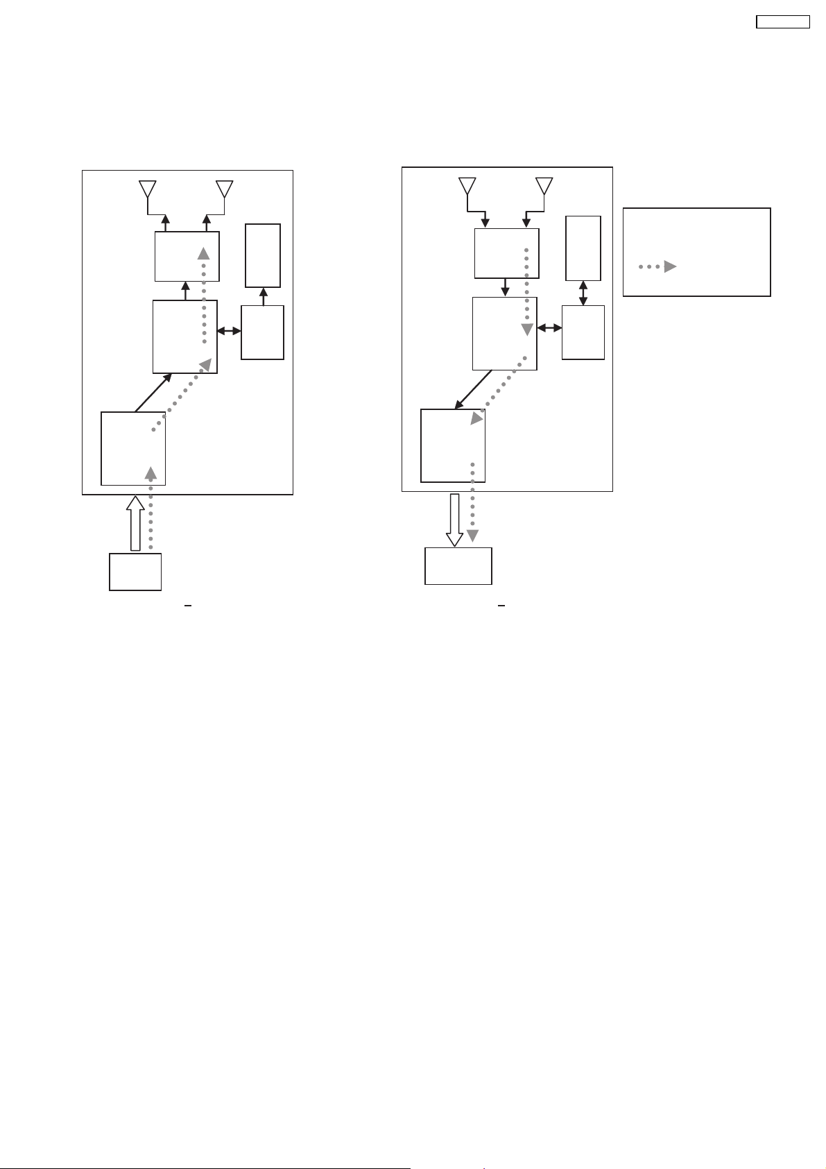
8.2.2.1. TX-TYPE A / RX-TYPE 1
Note:
RF
RF
EEPROM
EEPROM
- One way only
- FX65/FX66 signal flow
- FX65/FX66 only
SA-PT750PL
BB
MCU
ADC
CH2
IN
TX Type A
•
• Type A transmitter uses one ADC (Analog to Digital Converter) and transmits audio through Channel 2. Type 1 receiver (Rx)
• •
uses one DAC and output audio through Channel 2. The firmware (that is downloaded to EEPROM IC) multiplexes which
channel to listen to (in this case Channel 2 since type A is transmitting from channel 2 In) by setting the baseband accordingly.
DAC
CH2
OUT
BB
RX Type 1
MCU
23
S
SA-PT750PL
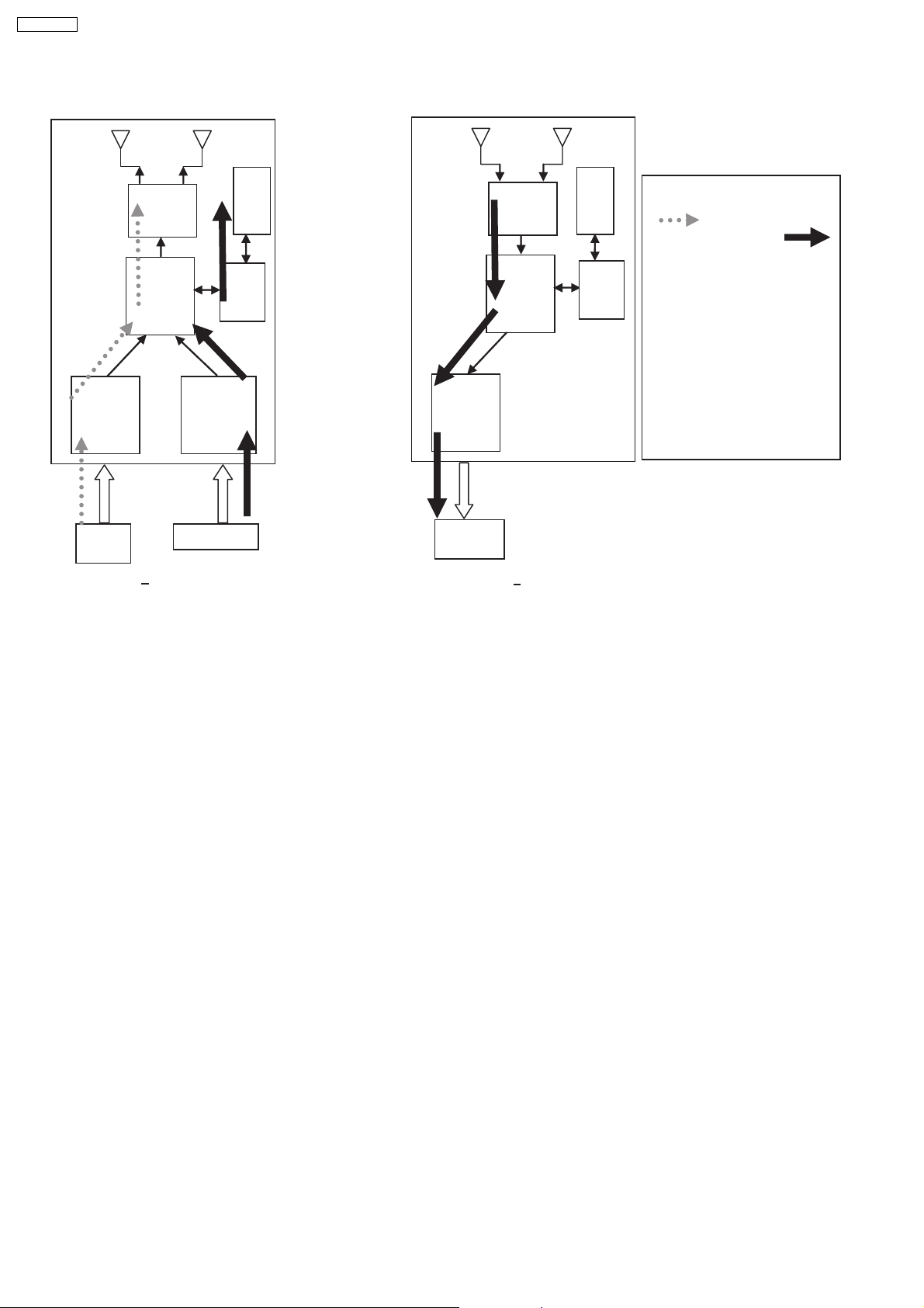
8.2.2.2. TX-TYPE B / RX-TYPE 2
RF
EEPROM
BB
MCU
ADC
ADC
DAC
RF
BB
EEPROM
MCU
Note:
- FX65/FX66 SIGNAL FLOW
- FX85 S
IGNAL FFLOW
- ONE WAY AND
SIMULTANEOUS
- FX65/FX66 + FX85
- FX65/FX66 TRANSMITTER NOT
USED, NEED TO IDSET
FX65/FX66
- TX TYPE B BUT RX
CHANGED FROM TYPE 2
TO TYPE 1, CH1 SIGNAL
REDIRECTED TO DAC
CH2
IN
TX Type B
•
• Type B transmitter uses two ADC (Analog to Digital Converter) to send audio streams from Channel 1 and Channel 2 for the
• •
CH1 IN
CH2
OUT
RX Type 2
FX65/FX66 surround sound and FX85 second room audio, respectively. Type 2 receiver outputs audio through Channel 2. The
software multiplexes which channel to listen to by setting the baseband accordingly. For example, if the receiver is configured
as an FX85 receiver (Type 2), the baseband is configured to accept Channel 1 audio transmission and redirect it to Channel
2 Out. If the receiver is set as an FX65/FX66 or wireless subwoofer, the baseband is configured to accept channel 2 audio
transmission and redirect it to the same Channel 2 Out.
8.2.3. Activation
•
• FX65/FX66 can be activated in the main unit by using either transmitter Type A or Type B and enabling surround sound by
• •
selecting Surround Music, DPL or Super Surround (Music/Movie).
•
• FX85 Wireless feature is enabled by default when the user uses transmitter type B.
• •
8.2.4. LED Indication
•
• For FX65/FX66, there will be two-color LED that will be used to indicate Power On and Link. If link, the two-color LED will be
• •
green, else, it will be red.
For FX85, the front panel will have LED indicators for Standby,, Wireless Link, Charge, Option and Music Port. During Power
On, Standby LED will be OFF. Only during power OFF will this LED be ON (Red). Wireless Link indicator will be ON (Green)
when link is established between TX and RX and OFF when link is lost. Pressing the selector button will toggle from any of the
selector modes Wireless, Option and Music port. Only the currently selected mode will be ON (Green), the other two will be
OFF. Charge LED will be ON (Red) once iPod charging is initiated.
8.2.5. Key Operation (FX85)
•
• Selector Button
• •
This button will be used to select Wireless, Option or M.Port and enabling the corresponding LED indicators for each mode.
During Power On, by default, selector mode is set to Wireless when power is initially supplied to the system. But during Power
On/OFF button, it will remember the last selector mode setting.
•
• Play Button
• •
This button will send command to the main unit to play CD/DVD as well as the iPod. This function is therefore meaningful only
24

if the second room selector is in Main Source (with the first room user in CD/DVD or iPod) and iPod.
•
• Stop Button
• •
This button will send command to the main unit to stop CD/DVD as well as the iPod. This function is therefore meaningful only
if the second room selector is in Main Source (if the first room user is in CD/DVD mode or iPod) and iPod.
•
• Forward Skip/Channel Up
• •
This button depends on the second room source currently selected. It will be interpreted as a Forward Skip by the main unit if
the second room source is in Main Source (with the first room user is in CD/DVD or iPod mode) and iPod. It will be interpreted
as a Channel Up (preset channels only) if the second room source is in FM, AM, or XM.
•
• Reverse Skip/Channel Down
• •
This button depends on the second room source currently selected. It will be interpreted as a Reverse Skip by the main unit if
the second room source is in Main Source (if the first room user is in CD/DVD or mode) and iPod. It will be interpreted as a
Channel Down (preset channels only) if the second room source is in FM, AM, or XM.
•
• Volume Control
• •
Volume control will be local to the FX85 module only. Default volume (TBD) will be set every time power is first supplied to the
system or during exit from stand by mode.
SA-PT750PL
•
• ID-setting Operation
• •
ID setting operation can be invoked by pressing fast-forward key in the main unit and three [3] key in the remocon. Once IDsetting is triggered, the receiver must press its ID-setting button within 60 seconds. During this period, the transmitter will be in
open connect mechanism whereby any receiver can pair with the transmitter. After this period elapsed, the transmitter will revert
back to using close connect code whereby only those receivers which have the same ID as the transmitter will be able to link.
The user also has the option to exit the ID setting operation by p ressing the same keys.
•
• iPod Detection and Charging
• •
iPod is detected once inserted on the FX85 and battery charging automatically starts.
−
− The iPod Charging in Standby Mode:
− −
OUpon iPod insertion detection and FX85 is in Power OFF (stand by), FX85 set will enter iPod charging Standby Mode.
OThe FX85’s CHARGE LED will light up whenever the iPod is charging.
OFX85 will charge the battery up to five hours. After this period, FX85 will not try to recharge the iPod.
OAfter battery full condition, even if the iPod is operated such as play, FX85 will not retry to recharge the iPod (timer will start
immediately once iPod is inserted).
ORe - charging of the battery in iPod Charging Standby Mode can be done only by removing and reinserting the iPod to the
dock.
−
− The iPod charging in Power On Mode:
− −
OThe iPod automatically charges its battery whenever it is connected during Power ON.
OThe FX85’s CHARGE LED will light up whenever the iPod is charging.
OFX85 will continue charging the iPod as long as it is inserted (no charging time limit of five hours).
25
SA-PT750PL
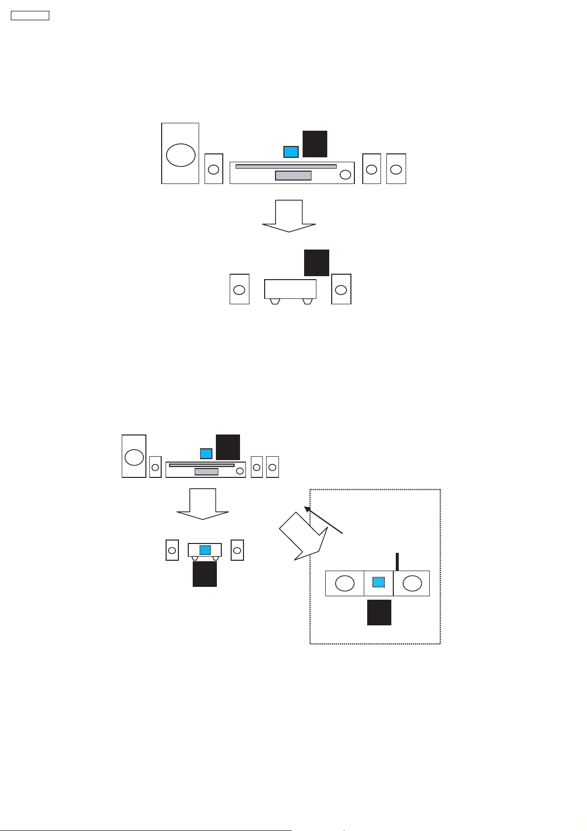
8.2.6. FX Configurations
There are four types of configurations for the FX series. This is explained by the following illustrations below:
Case 1: FX65/FX66
•
• This is the basic configuration of FX65/FX66 whereby it is only receiving wireless surround audio signal from the main set. This
• •
uses a Type A transmitter which is only able to send audio in one direction. Audio is sent using streams AB through Ch 2.
TX
A
RX
FX65/FX66
1
CH2/AB
Case 2 A: FX65/FX66 + FX85
•
• In this configuration, a second receiver, an FX85, in another room is listening to another audio source from the main set. The
• •
FX85 also is able to send command to the main set such as Play, Stop, Skip, and Preset Tuner Channel Up/Down. This
configuration uses Type B transmitter which is an upgrade of the Type A and can be used on Type 1 (FX65/FX66). This
transmitter is able to send audio signal for second room via Ch 1 and first room via Ch 2.
In this configuration, streams AB is used to transmit the audio from main unit to the first room Type 1 receiver (FX65/FX66) via
Ch 2. While the second room audio is transmitted through stream CD via Ch 1.
TX
B
Multi-room + Multi source
RX
CH1/CD
CH2/AB
RX
1
FX65/FX66
Case 3 A: Wireless Subwoofer
•
• This configuration, Type A transmitter send signals to subwoofer and Type 1 receiver (FX65/FX66) via channel 2, which is the
• •
same audio signals sent to FX65/FX66 as well. The subwoofer only decodes the low frequency signal.
1
FX85
26
1
RX
TX
A
CH2/AB
RX
1
Case 3 B: FX65/FX66 + FX85 + Wireless Subwoofer (for PTX7, PT1050)
•
• In this configuration, all audio source for the Type 1 subwoofer and Type 1 first room receiver (FX65/FX66) through streams AB
• •
via Ch 2 and Type 2 second room receiver (FX85) comes from transmitter B through streams CD via Ch 1. For this
configuration, the user must perform ID setting for FX85 if it is sold as an accessory, but for bundled type, it already is paired
with the transmitter.
CH2/AB
SA-PT750PL
B
CH2/AB
RX
RX
1
1
RX
CH2/AB
Multi-room + Multi source
CH1-CD
RX
1
27
Y
SA-PT750PL
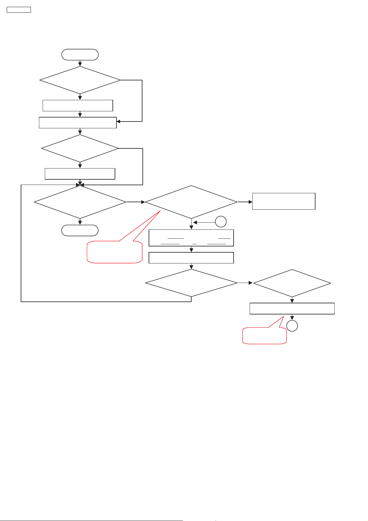
8.2.7. User Operation Flow
START
Is Tx card
inserted?
N
Insert Tx card
POWER ON MAINSET
Is there audio
source playing?
N
Play music
Is music heard on
wireless surround
speaker?
Y
DONE
TX-RX probably not
paired. Do ID setting
process
Y
N
Press FF Key in Mainset and 3 key
on remocon until "P" led displays
Is wireless link led
blinking?
Y
Press ID set button on receiver
Is wireless link led
blinking?
N
A
Y
CHECK FOR SPEAKER
WIRE CONNECTIONS
Is wireless
receiver on?
Power on receiver
A
Repeat ID set
process
8.2.8. Baseband Settings Update from EEPROM IC
•
• The software will read from an external EEPROM IC to get the selected baseband IC settings. Not all baseband register
• •
settings (a total o f 512 bytes) will be read from the EEPROM IC, though. Aside from getting the baseband settings from the
EEPROM IC, it is also used to enable FCC testing, select the application type and entering into doctor mode (this can be
enabled also by sending a command via the main unit).
8.2.9. Doctor Mode
•
• For normal operation but automatic frequency selection is disabled, it can enter into Doctor Mode. This feature is hidden from
• •
normal user and will be used by the s ervice center to fix to a particular RF Channel. With doctor mode, the user can disable
frequency automatic allocation and sniffer and be able to select a fix RF Channel (Channels 1, 2 or 3) by a combination or
remote control keys. Refer to Section 9.4 for Wireless Doctor Mode.
28
9 Self-Diagnosis and Special Mode Setting
9.1. Service Mode Summary Table
The service modes can be activated by pressing various button combination on the main unit and remote control unit.
Below is the summary for the various modes for checking:
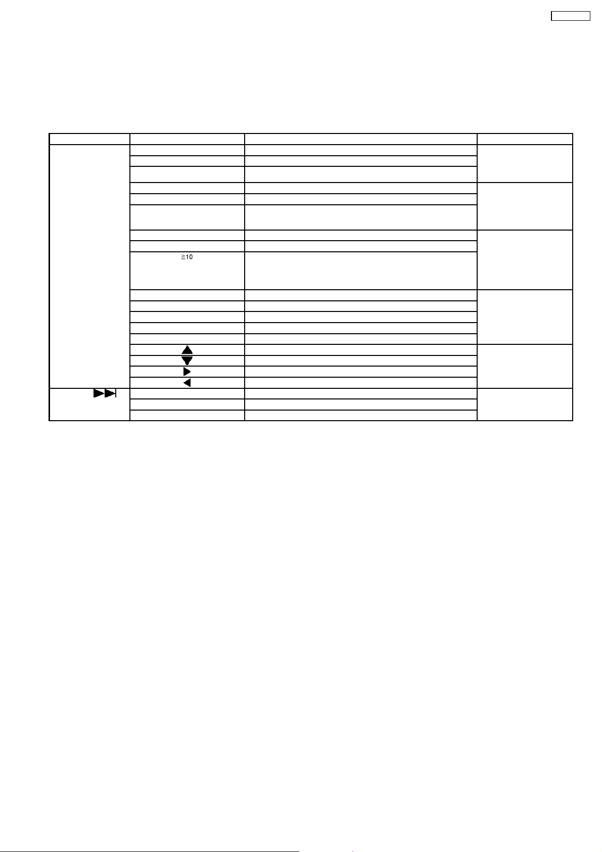
Player buttons Remote control unit buttons Application Note
[STOP] [0] Error code check. (Refer to the section
[5] Jitter checking.
[PAUSE] Initial setting of laser drive current.
[FUNCTIONS] DVD laser drive current check. (Refer to the section
[1] ADSC internal RAM data check.
3] CD laser drive current check.
“9.2.1. Service Mode
Table 1” for more
information.)
“9.2.2. Service Mode
Table 2” for more
information.)
SA-PT750PL
[6] Region display and mode. (Refer to the section
[7] Micro-processor firmware version check.
[ ] Initialization of the player (factory setting is restored).
Used after replacement of Micro-processor (DV5 LSI) IC, FLASH
ROM IC (IC8651), EEPROM IC (IC8611) and DVD Module
P.C.B.
[8] DVD Module P.C.B. firmware version check. (Refer to the section
[MENU] Communication error display.
[TOP MENU] ECC error check.
[EQ] CPPM/CRM keys check.
[ENTER] DVD Module P.C.B. reset.
[ ] Timer 1 check. (Refer to the section
[ ] Timer 1 reset.
[ ] Timer 2 check.
[ ] Timer 2 reset.
[STOP]+[ ] [1] Combination reliability test mode. (Refer to the section
[2] OPEN/CLOSE reliability test mode.
[3] Tray rotation reliability test mode.
“9.2.3. Service Mode
Table 3“ for more
information.)
“9.2.4. Service Mode
Table 4“ for more
information.)
“9.2.5. Service Mode
Table 5“ for more
information.)
“9.2.7.1. Test Mode List”
for more information.)
Note:
An error code will be canceled if a power supply is turned OFF.
*1: CPPM is the copy guard function beforehand written in the disk for protection of copyrights.
*2: CEC is the consumer electronic control used for high-level user control of HDMI-connected devices.
*3: HDCP is the specification developed to control digital audio & video contents transmission for DVI or HDMI connections.
9.2. Service Mode Table (Main Unit)
By pressing various button combinations on the main unit and remote control unit, you can activate the various service modes for
checking.
Special Note:
•
• Due to the limitations of the no. characters that can be shown on the FL Display, the “FL Display” button on the remote
• •
control unit can be used to show the two display pages. (Display 1 / Display 2).
•
• Refer to Section 7.1 for the section on “Remote Control Key Buttons Operations”.
• •
29
SA-PT750PL
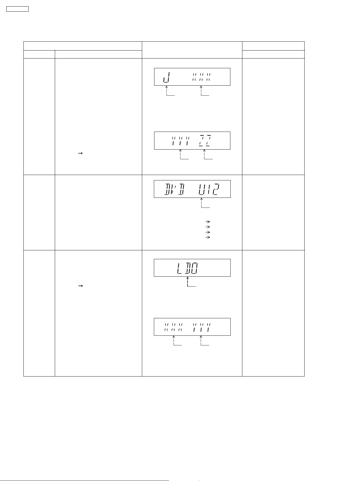
9.2.1. Service Mode Table 1
Mode Name
Jitter check
Error code
check
Item
Description
Jitter check.
Jitter rate is measured and displayed.
Measurement is repeatedly done in
the cycle of one second. Read error
counter starts from zero upon mode
setting.
When target block data failed to be
read out, the counter advances by one
increment. When the failure is caused
by minor error, it may be corrected
when retried to enable successful
reading.
In this case, the counter advances by
one. When the error persists even
after retry, the counter may jump by
two or more.
FL Display sequence:
Display 1 2.
Error code check
The latest error code stored in the
EEPROM IC is displayed.
Note: Refer to "Section 9.5 DVD Self
Diagnostic Function-Error Code" for
more detailed information on the error
codes.
FL Display
(Display 1)
Jitter check
mode
Jitter rate is shown in decimal notation to
one place of decimal.
Focus drive value is shown in hexadecimal
notation.
(Display 2)
Lead
Error
Counter
Error code (play_err) is expressed in the
following convention.
Error code = 0 x DAXX is expressed: DVDnn U12
Error code = 0 x DBXX is expressed: DVDnn H12
Error code = 0 x DXXX is expressed: DVDnn F123
Error code = 0 x 0000 is expressed: DVDnn F--* "xx" denotes the error code
Jitter rate
Focus Drive
Value
U / H / F
Key Operation
Front Key
In STOP (no disc) mode,
press [STOP] button on the
main unit, and [5] button on
the remote control unit.
Press [POWER] button to
exit.
Press [FL Display] on
remote control unit for next
page (FL Display).
In STOP (no disc) mode,
press [STOP] button on the
main unit, and [0] button on
the remote control unit. * With
pointing of cursor up and
down on display.
Cancelled automatically
5 seconds later.
To exit, press [POWER]
button on main unit or
remote control.
Initial setting
of laser drive
current
Initial setting of laser drive current.
Initial current value for the DVD laser
and CD laser is separately saved in
the EEPROM IC.
FL Display sequence:
Display 1 2.
(Display 1)
Laser current
measurement
CD
Laser
mode
DVD Laser
The value denotes the current in decimal
notation.
(Display 2)
The above example shows the initial
current is XXXmA and YYYmA for CD
laser and DVD laser respectively when
the laser is switched on.
In STOP (no disc) mode,
press [STOP] button on the
main unit, and [PAUSE]
button on the remote
control unit.
Cancelled automatically
5 seconds later.
Press [FL Display] on
remote control unit for next
page (FL Display) on values
of laser drive current.
30
 Loading...