

Panasonic SAPT-170-PH Service manual
PSG0904028CE
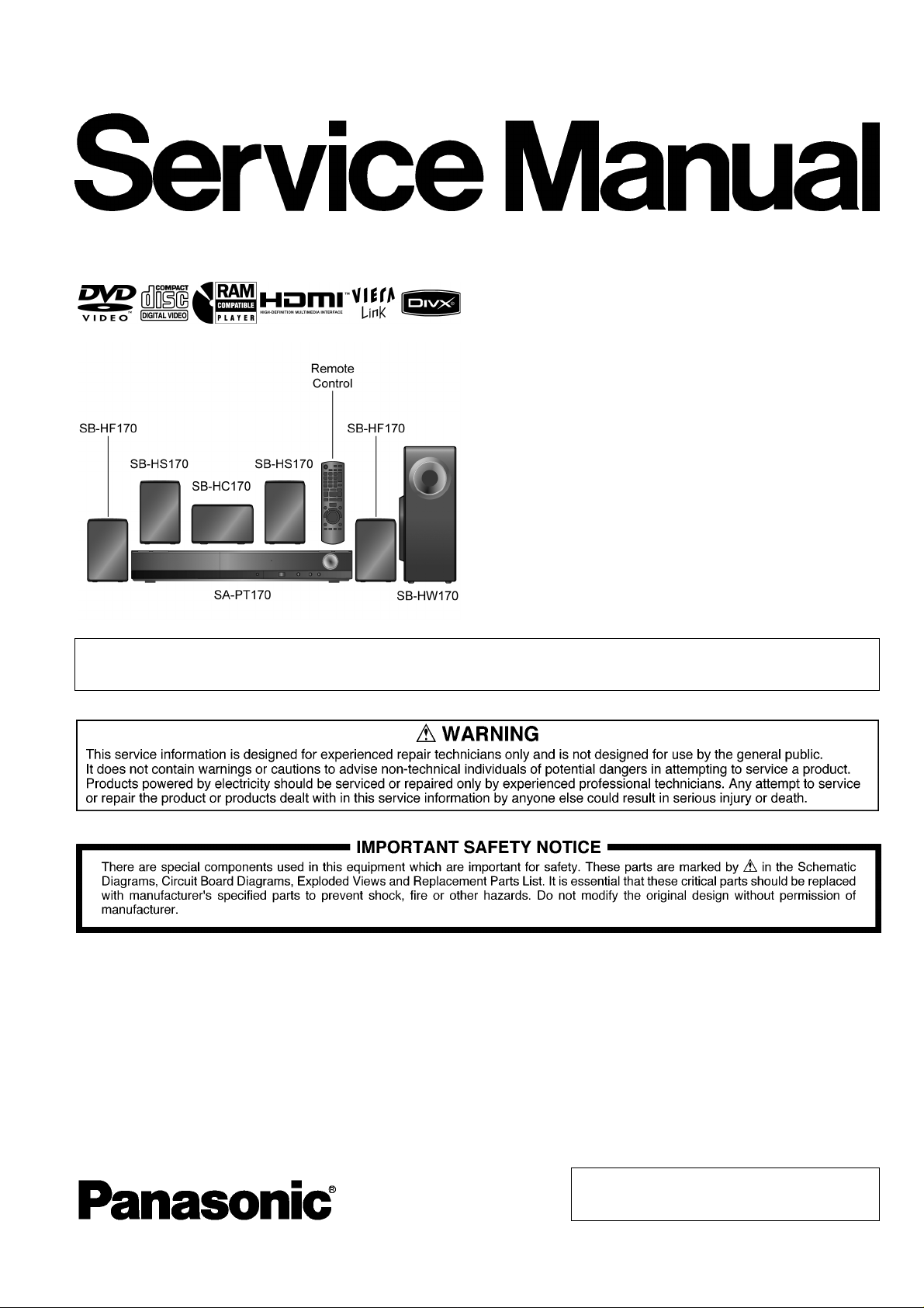
DVD Home Theater Sound System
Model No. SA-PT170PH
SA-PT170PR
Product Color: (K)...Black Type
Notes: This model’s DVD mechanism unit is DLS6. Please refer to the original service manual
(Order No. MD0801003CE) for this mechanism
TABLE OF CONTENTS
PAGE PAGE
1 Safety Precautions----------------------------------------------- 3
1.1. GENERAL GUIDELINES--------------------------------3
1.2. Before Use -------------------------------------------------- 3
1.3. Before Repair and Adjustment------------------------- 3
1.4. Protection Circuitry----------------------------------------4
1.5. Safety Parts Information--------------------------------- 4
2 Warning-------------------------------------------------------------- 6
2.1. Prevention of Electrostatic Discharge (ESD)
to Electrostatic Sensitive (ES) Devices---------------6
2.2. Precaution of Laser Diode-------------------------------7
2.3. Service caution based on Legal restrictions --------8
2.4. Handling Precautions for Traverse Unit--------------9
3 Service Navigation --------------------------------------------- 11
3.1. Service Information-------------------------------------- 11
4 Specifications----------------------------------------------------12
© Panasonic Corporation 2009. All rights reserved.
Unauthorized copying and distribution is a violation
of law.

5 Location of Controls and Components------------------14
5.1. Remote Control Key Button Operations------------14
5.2. Main Unit Key Button Operations --------------------15
5.3. Using the VIERA Link “HDAVI Control”-------------16
5.4. USB Connection and Operations --------------------18
5.5. Music Port Connection and Operations ------------19
5.6. Speaker Connection-------------------------------------20
5.7. Disc Information ------------------------------------------21
6 Self-Diagnosis and Special Mode Setting --------------23
6.1. Service Mode Summary Table------------------------23
6.2. Service Mode Table--------------------------------------23
6.3. DVD Self Diagnostic Function-Error Code---------30
6.4. Sales Demonstration Lock Function ----------------33
6.5. Firmware Version-Up Information--------------------34
7 Troubleshooting Guide----------------------------------------36
7.1. Troubleshooting Guide for F61 and/or F76-------- 36
7.2. Basic Troubleshooting Guide for Traverse
Unit (DVD Module P.C.B.)------------------------------43
7.3. Basic Troubleshooting Guide for HDMI AV
Output-------------------------------------------------------44
8 Service Fixture & Tools---------------------------------------46
8.1. Service Tools and Equipment-------------------------46
9 Disassembly and Assembly Instructions---------------47
9.1. Disassembly Flow Chart--------------------------------48
9.2. Main Components and P.C.B. Locations-----------49
9.3. Disassembly of Top Cabinet-------------------------- -50
9.4. Disassembly of Rear Panel----------------------------50
9.5. Disassembly of DVD Mechanism Unit (DLS6)---- 50
9.6. Disassembly of Front Panel Assembly -------------51
9.7. Disassembly of Panel, Power Button P.C.B. ------52
9.8. Disassembly of MPort / USB P.C.B.-----------------53
9.9. Disassembly of Mic P.C.B.-----------------------------53
9.10. Disassembly of DVD Lid--------------------------------53
9.11. Disassembly of AC Inlet P.C.B.-----------------------54
9.12. Disassembly of Main P.C.B.---------------------------55
9.13. Disassembly of Analog Amp P.C.B. -----------------56
9.14. Replacement of 2CH BTL Power Amplifier IC
(IC5100) ----------------------------------------------------57
9.15. Replacement of 2CH BTL Power Amplifier IC
(IC5200) ----------------------------------------------------58
9.16. Replacement of 2CH BTL Power Amplifier IC
(IC5300) ----------------------------------------------------59
9.17. Disassembly of SMPS P.C.B & Voltage
Selector P.C.B.---------------------------------- --------- -61
9.18. Replacement of Switching Regulator IC
(IC5701) ----------------------------------------------------62
9.19. Replacement of Regulator Diode (D5802)---------63
9.20. Disassembly of DVD Module P.C.B.-----------------64
9.21. Assembling and Disassembling of Traverse
Unit-----------------------------------------------------------65
10 Service Position-------------------------------------------------67
10.1. Checking & Servicing Main P.C.B.-------------------67
10.2. Checking & Analog Amp P.C.B. ----------------------67
10.3. Checking & Servicing SMPS & AC Inlet P.C.B.---70
10.4. Checking & Servicing DVD Module P.C.B. --------71
11 Voltage & Waveform Chart-----------------------------------73
11.1. DVD Module P.C.B. (1/4)-------------------------------73
11.2. DVD Module P.C.B. (2/4)-------------------------------74
11.3. DVD Module P.C.B. (3/4)-------------------------------75
11.4. DVD Module P.C.B. (4/4)-------------------------------76
1 1 .5. Main P.C.B. (1/2) -----------------------------------------77
1 1 .6. Main P.C.B. (2/2)----------------------------------------- 78
11.7. Panel P.C.B.----------------------------------------------- 78
11.8. Analog Amp P.C.B.-------------------------------------- 79
11.9. SMPS P.C.B.---------------------------------------------- 80
1 1.10. Mic P.C.B.-------------------------------------------------- 81
11.11. Waveform Table (1/4)----------------------------------- 82
1 1.12. Waveform Table (2/4)----------------------------------- 83
1 1.13. Waveform Table (3/4)----------------------------------- 84
1 1.14. Waveform Table (4/4)----------------------------------- 85
12 Illustration of ICs, Transistor and Diode---------------- 86
13 Overall Simplified Block Diagram------------------------- 87
14 Block Diagram--------------------------------------------------- 88
14.1. System Control ------------------------------------------ 88
14.2. DVD (SERVO)-------------------------------------------- 89
14.3. DVD (Audio)----------------------------------------------- 90
14.4. DVD (HDMI)----------------------------------------------- 91
14.5. Video-------------------------------------------------------- 92
14.6. Audio-------------------------------------------------------- 93
14.7. Analog Amp----------------------------------------------- 94
14.8. Power------------------------------------------------------- 95
15 Wiring Connection Diagram -------------------------------- 96
16 Schematic Diagram Notes----------------------------------- 97
17 Schematic Diagram-------------------------------------------- 99
17.1. DVD Module Circuit------------------------------------- 99
17.2. Main Circuit-----------------------------------------------104
17.3. Panel Circuit ---------------------------------------------108
17.4. MPort/USB & Power Button Circuit ----------------109
17.5. Analog Amp Circuit-------------------------------------110
17.6. SMPS Circuit---------------------------------------------111
17.7. AC Inlet & Voltage Selector Circuit----------------- 113
17.8. Mic Circuit ------------------------------------------------114
18 Printed Circuit Board-----------------------------------------115
18.1. DVD Module P.C.B. ------------------------------------115
18.2. Main P.C.B.------------------------- --------- ------------- 116
18.3. Panel, MPort/USB, Power Button & AC Inlet
P.C.B.------------------------------------------------------117
18.4. Analog Amp P.C.B.-------------------------------------118
18.5. SMPS P.C.B.--------------------------------------------- 119
18.6. Mic & Voltage Selector P.C.B.-----------------------120
19 Terminal Function of ICs------------------------------------121
19.1. IC2001 (RFKWMPT470EB): IC MICRO
PROCESSOR -------------------------------------------121
19.2. IC6901(C0HBB0000057): IC FL Driver-----------121
20 Exploded View and Replacement Parts List----------123
20.1. Exploded View and Mechanical Replacement
Part List ---------------------------------------------------123
20.2. Electrical Replacement Part List--------------------127
2
1 Safety Precautions
1.1. GENERAL GUIDELINES
1. When servicing, observe the original lead dress. If a short circuit is found, replace all parts which have been overheated or
damaged by the short circuit.
2. After servicing, see to it that all the protective devices such as insulation barriers, insulation papers shields are properly
installed.
3. After servicing, carry out the following leakage current checks to prevent the customer from being exposed to shock hazards.
1.1.1. LEAKAGE CURRENT COLD CHECK
1. Unplug the AC cord and connect a jumper between the two prongs on the plug.
2. Measure the resistance value, with an ohmmeter, between the jumpered AC plug and each exposed metallic cabinet part on
the equipment such as screwheads, connectors, control shafts, etc. When the exposed metallic part has a return path to the
chassis, the reading should be between 1MΩ and 5.2MΩ.
When the exposed metal does not have a return path to the chassis, the reading must be
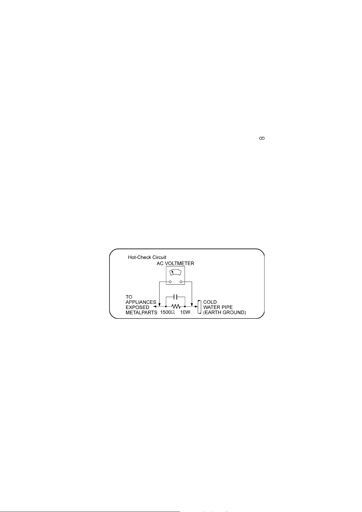
1.1.2. LEAKAGE CURRENT HOT CHECK
1. Plug the AC cord directly into the AC outlet. Do not use an isolation transformer for this check.
2. Connect a 1.5kΩ, 10 watts resistor, in parallel with a 0.15µF capacitors, between each exposed metallic part on the set and a
good earth ground such as a water pipe, as shown in Figure 1.
3. Use an AC voltmeter, with 1000 ohms/volt or more sensitivity, to measure the potential across the resistor.
4. Check each exposed metallic part, and measure the voltage at each point.
5. Reverse the AC plug in the AC outlet and repeat each of the above measurements.
6. The potential at any point should not exceed 0.75 volts RMS. A leakage current tester (Simpson Model 229 or equiva lent)
may be used to make the hot checks, leakage current must not exceed 1/2 milliamp. In case a measurement is outside of the
limits specified, there is a possibility of a shock hazard, and the equipment should be repaired and rechecked before it is
returned to the customer.
Figure 1
1.2. Before Use
Be sure to disconnect the mains cord before adjusting the voltage selector.
Use a minus (-) screwdriver to set the voltage selector (on the rear panel) to the voltage setting for the area in which the unit will be
used. (If the power supply in your area is 117V or 120V, set the “117V or 120V” position.)
Note that this unit will be seriously damaged if this setting is not made correctly. (There is no voltage selector for some countries,
the correct voltage is already set.)
1.3. Before Repair and Adjustment
Disconnect AC power to discharge unit AC Capacitors as such (C5700, C5701, C5702, C5703 , C5706, C5707, C 5708) through a
10 Ω, 10 W resistor to ground.
Caution:
DO NOT SHORT-CIR CUIT DIRECTLY (with a screwdriver blade, for instance), as this may destroy solid state devices.
After repairs are completed, restore power gradually using a variac, to avoid overcurrent.
Current consumption at AC 220-240 V, 50 Hz in NO SIGNAL mode volume minimal should be ~ 500 mA.
Current consumption at AC 110-127 V, 50/60 Hz in NO SIGNAL mode volume minimal should be ~ 600 mA.
3
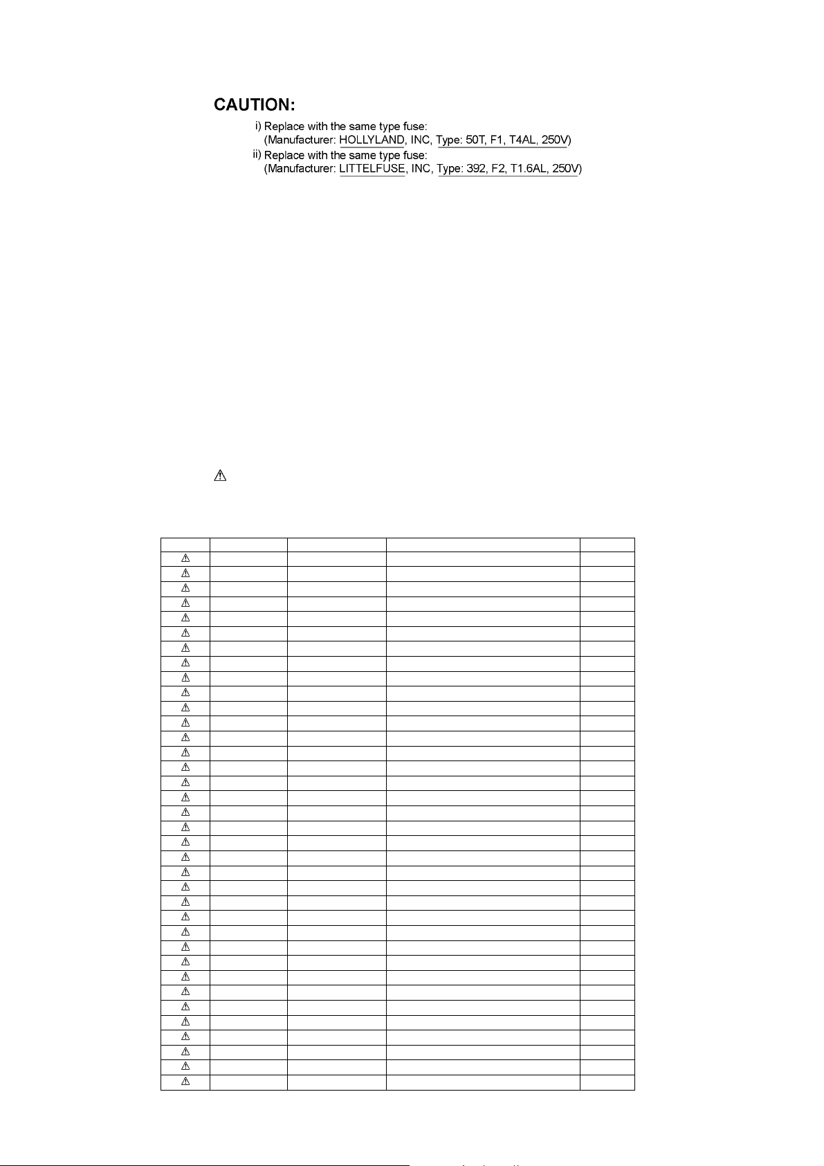
1.3.1. Caution for fuse replacement
1.4. Protection Circuitry
The protection circuitry may have operated if either of the following conditions are noticed:
• No sound is heard when the power is turned on.
• Sound stops during a performance.
The function of this circuitry is to prevent circuitry damage if, for example, the positive and negative speaker connection wires are
“shorted”, or if speaker systems with an impedance less than the indicated rated impedance of the amplifier are used.
If this occurs, follow the procedure outlines below:
1. Turn off the power.
2. Determine the cause of the problem and correct it.
3. Turn on the power once again after one minute.
Note:
When the protection circuitry functions, the unit will not operate unless the power is first turned off and then on again.
1.5. Safety Parts Information
Safety Parts List:
There are special components used in this equipment which are important for safety.
These parts are marked by in the Schematic Diagrams, Exploded View & Replacement Parts List. It is essential that these
critical parts should be replaced with manufacturer’s specified parts to prevent shock, fire or other hazards. Do not modify the
original design without permission of manufacturer.
Safety Ref. No. Part No. Part Name & Description Remarks
18 RGRX0071C-E REAR PANEL PH-K
18 RGRX0071C-F REAR PANEL PR-K
31 RKMX0141-1K3 TOP CABINET
50 REXX0728 BLACK WIRE (SMPS-AC)
51 REXX0730 RED WIRE (SMPS-AC)
55 REXX0643 BLUE WIRE (VOLT. SELECTOR-SMPS)
56 REXX0729 WHITE WIRE (VOLT. SELECTOR-SMPS)
301 RD-DDTX001-V TRAVERSE UNIT (RTL)
A2 K2CJ2DA00006 AC CORD PR-K
A2 K2CQ2CA00007 AC CORD PH-K
A3 RQTX0245-M O/I BOOK (Sp)
PCB7 REPX0729B SMPS P.C.B (RTL)
PCB8 REPX0729B AC INLET P.C.B (RTL)
PCB9 REPX0729B VOLTAGE SELECTOR P.C.B (RTL)
DZ5701 ERZV10V511CS ZNR
S5701 K0ABCA000007 SW AC VOLTAGE SELECTOR
L5702 ELF19H015A LINE FILTER
L5703 ELF19H015A LINE FILTER
T2900 G4D1A0000117 SWITCHING TRANSFORMER
T5701 ETS35BC2P6AC MAIN TRANSFORMER
T5751 ETS19AB2A6AG BACKUP TRANSFORMER
PC5702 B3PBA0000402 PHOTO COUPLER
PC5720 B3PBA0000402 PHOTO COUPLER
PC5799 B3PBA0000402 PHOTO COUPLER
RY5701 K6B1AEA00003 RELAY
F1 K5D402BK0007 FUSE
F2 K5G162B00016 FUSE
FP2901 K5H1022A0011 PROTECTOR
TH5702 D4CAA5R10001 THERMISTOR
P5701 K2AA2B000017 AC INLET
C5700 F1BAF1020020 1000pF
C5701 ECQU2A104MLC 0.1uF
C5702 ECQU2A104MLC 0.1uF
C5703 ECQU2A104MLC 0.1uF
C5706 F1BAF1020020 1000pF
C5707 F1BAF1020020 1000pF
4

Safety Ref. No. Part No. Part Name & Description Remarks
C5708 F1BAF1020020 1000pF
5

2Warning
2.1. Prevention of Electrostatic Discharge (ESD) to Electrostatic Sensitive
(ES) Devices
Some semiconductor (solid state) devices can be damaged easily by static electricity. Such components commonly are called Electrostatically Sensitive (ES) Devices. Examples of typical ES devices are integrated circuits and some field-effect transistors and
semiconductor “chip” components. The following techniques should be used to help reduce the incid ence of component damage
caused by electrostatic discharge (ESD).
1. Immediately before handling any semiconductor component or semiconductor-equipped assembly, drain off any ESD on your
body by touching a known earth ground. Alternatively, obtain and wear a commercially available discharging ESD wrist strap,
which should be removed for potential shock reasons prior to applying power to the unit under test.
2. After removing an electrical assembly equipped with ES devices, place the assembly on a cond uctive surface su ch as a luminum foil, to prevent electrostatic charge build up or exposure of the assembly.
3. Use only a grounded-tip soldering iron to solder or unsolder ES devices.
4. Use only an anti-static solder removal device. Some solder removal devices not classified as “anti-static (ESD protected)” can
generate electrical charge sufficient to damage ES devices.
5. Do not use freon-propelled chemicals. These can generate electrical charges sufficient to damage ES devices.
6. Do not remove a replacement ES device from its protective package until immediately before you are ready to install it. (Most
replacement ES devices are packaged with leads electrically shorted together by conductive foam, aluminum foil or comparable conductive material).
7. Immediately before removing the protective material from the leads of a replacement ES device, touch the protective material
to the chassis or circuit assembly into which the device will be installed.
Caution:
Be sure no power is applied to the chassis or circuit, and observe all other safety precautions.
8. Minimize bodily motions when handling unpackaged replacement ES devices. (Otherwise harmless motion such as the
brushing together of your clothes fabric or the lifting of your foot from a carpeted floor can generate static electricity (ESD) suf-
ficient to damage an ES device).
6
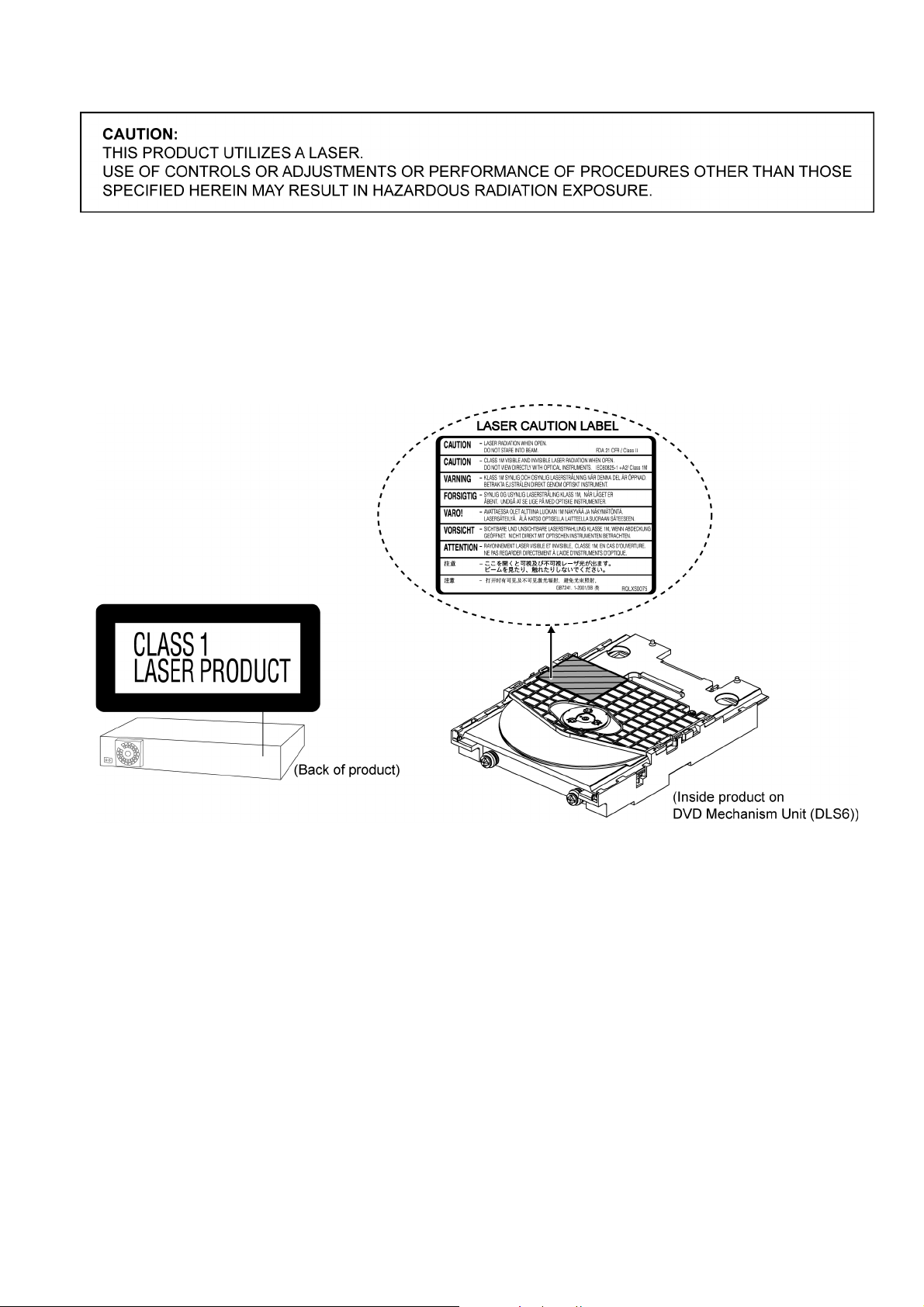
2.2. Precaution of Laser Diode
Caution:
This product utilizes a laser diode with the unit turned “on”, invisible laser radiation is emitted from the pickup lens.
Wavelength: 655 nm (DVD)/785 nm (CD)
Maximum output radiation power from pickup: 100 µW/VDE
Laser radiation from the pickup unit is safety level, but be sure the followings:
1. Do not disassemble the pickup unit, since radiation from exposed laser diode is dangerous.
2. Do not adjust the variable resistor on the pickup unit. It was already adjusted.
3. Do not look at the focus lens using optical instruments.
4. Recommend not to look at pickup lens for a long time.
7

2.3. Service caution based on Legal restrictions
2.3.1. General description about Lead Free Solder (PbF)
The lead free solder has been used in the mounting process of all electrical components on the printed circuit boards us ed for this
equipment in considering the globally environmental conservation.
The normal solder is the alloy of tin (Sn) and lead (Pb). On the other hand, the lead free solder is the alloy mainly consists of tin
(Sn), silver (Ag) and Copper (Cu), and the melting point of the lead free solder is higher approx.30 degrees C (86°F) more than that
of the normal solder.
Definition of PCB Lead Free Solder being used
The letter of “PbF” is printed either foil side or components side on the PCB using the lead free solder.
(See right figure)
Service caution for repair work using Lead Free Solder (PbF)
• The lead free solder has to be used when repairing the equipment for which the lead free solder is used.
(Definition: The letter of “PbF” is printed on the PCB using the lead free solder.)
• To put lead free solder, it should be well molten and mixed with the original lead free solder.
• Remove the remaining lead free solder on the PCB cleanly for soldering of the new IC.
• Since the melting point of the lead free solder is higher th an that of the normal lead solder, it takes the longer time to melt the
lead free solder.
• Use the soldering iron (more than 70W) equi pped with th e temperature contro l after setting the temp erature at 350±30 degrees
C (662±86°F).
Recommended Lead Free Solder (Service Parts Route.)
• The following 3 types of lead free solder are available through the service parts route.
RFKZ03D01K-----------(0.3mm 100g Reel)
RFKZ06D01K-----------(0.6mm 100g Reel)
RFKZ10D01K-----------(1.0mm 100g Reel)
Note
* Ingredient: tin (Sn), 96.5%, silver (Ag) 3.0%, Copper (Cu) 0.5%, Cobalt (Co) / Germanium (Ge) 0.1 to 0.3%
8
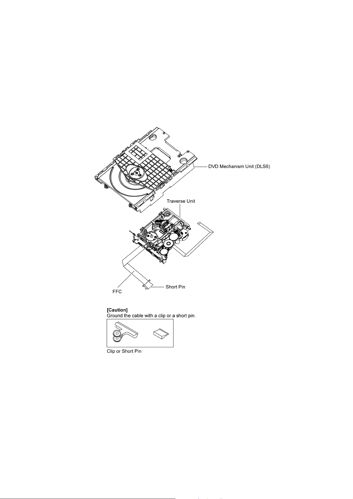
2.4. Handling Precautions for Traverse Unit
The laser diode in the optical pickup unit may break down du e to static electricity of clothes or human body. Special care must be
taken avoid caution to electrostatic breakdown when servicing and handling the laser diode in the traverse unit.
2.4.1. Cautions to Be Taken in Handling the Optical Pickup Unit
The laser diode in the optical pickup unit ma y be damaged due to electrostatic discharge genera ting from clothes or human body.
Special care must be taken avoid caution to electrostatic discharge damage when servicing the laser diode.
1. Do not give a considerable shock to the optical pickup unit as it has an extremely high-precise structure.
2. To prevent the laser diode from the electrostatic discharge damage , the flexible cable of the optical pickup unit removed
should be short-circuited with a short pin or a clip.
3. The flexible cable may be cut off if an excessive force is applied to it. Use caution when handling the flexible cable.
4. The antistatic FPC is connected to the new optical pickup unit. After replacing the optical pickup unit and connecting the flexible cable, cut off the antistatic FPC.
Figure 1
2.4.2. Grounding for electrostatic breakdown prevention
Some devices such as the DVD player use the optical pickup (laser diode) and the optical pickup will be damaged by static electricity in the working environment. Proceed servicing works under the working environment where grounding works is completed.
2.4.2.1. Worktable grounding
1. Put a conductive material (sheet) or iron sheet on the area where the optical pickup is placed, and ground the sheet.
9

2.4.2.2. Human body grounding
1. Use the anti-static wrist strap to discharge the static electricity form your body.
Figure 2
10

3 Service Navigation
3.1. Service Information
This service manual contains technical information which will allow service personnel’s to understand and service this model.
Please place orders using the parts list and not the drawing reference numbers.
If the circuit is changed or modified, this information wil l be followed b y supplement se rvice manual to be fil ed with origin al se rvice
manual.
• DVD Mechanism Unit (DLS6):
1) This model uses DVD Mechanism Unit (DLS6).
2) This service manual does not contain the following information on DLS6
* Schematic Diagram, Block Diagram and P.C.B. layout of DLS6 P.C.B.
* Parts List for individual parts of DVD Mechanism Unit (DLS6).
* Exploded View and Part List for individual parts of DLS6 mechanism.
Please refer to original service manual (Order No. MD0801003CE)
• Printed Circuit Boards:
The following category are supplied as an assembled module.
• DVD Module P.C.B. (RFKBX0681A-M).
• Micro-processor & EEPROM:
1) The following components are supplied as an assembled part.
• Micro-processor IC, IC2001 (RFKWMPT470EB).
• EEPROM IC, IC2003 (RFKWEPT470EB).
• Speaker system
1) For information, please refer to original service manual, SB-PT170EG-K (Order No. PSG0903020CE).
11

4 Specifications
Main unit SA-PT170PH/PR
O
OGENERAL
OO
Power supply: AC 110 to 127V/AC 220 to
240V, 50/60 Hz
Power consumption: This unit 90 W
Power consumption in standby mode:
approx. 0.2 W
Dimensions (W××××H××××D): 430 mm×63 mm×325 mm
Mass: This unit 3.14 kg
Operating temperature range: 0 °C to +40 °C
Operating humidity range: 35% to 80% RH
(no condensation)
O
OAMPLIFIER SECTION
OO
RMS Output Power: Dolby Digital Mode
Front Ch:
55 W per channel (5 Ω), 1 kHz, 10% THD
Surround Ch:
55 W per channel (5 Ω), 1 kHz, 10% THD
Center Ch:
55 W per channel (5 Ω), 1 kHz, 10% THD
Subwoofer Ch:
55 W per channel (5 Ω), 100 Hz, 10% THD
Total RMS Dolby Digital mode power:
330 W
PMPO output power:
2800 W
DIN Output Power: Dolby Digital Mode
Front Ch:
30 W per channel (5 Ω), 1 kHz, 1% THD
Surround Ch:
30 W per channel (5 Ω), 1 kHz, 1% THD
Center Ch:
30 W per channel (5 Ω), 1 kHz, 1% THD
Subwoofer Ch:
30 W per channel (5 Ω), 100 Hz, 1% THD
Total DIN Dolby Digital mode power:
180 W
O
OTUNER, TERMINALS SECTION
OO
Preset Memory: FM 30 stations
Frequency Modulation (FM)
Frequency range:
87.50-108.00 MHz (50-kHz step)
Antenna terminals: 75 Ω (unbalanced)
Digital audio input
Optical digital input: Optical terminal
Sampling frequency: 32 kHz, 44.1 kHz, 48 kHz
USB Port
USB standard: USB 2.0 full speed
Media file format support: MP3 (*.mp3)
WMA (*.wma)
JPEG (*.jpg) (*.jpeg)
DivX (*.divx) (*.avi)
MPEG4 (*.asf)
USB device file system: FAT12, FAT16, FAT32
USB Port power: Max. 500 mA
Bit rate: Up to 4Mbps (Divx)
Mic jack
Sensitivity: 0.7 mV, 1.2 kΩ
Terminal: Mono, 6.3mm jack (2 system)
Music Port (Front)
Sensitivity: 100 mV, 3.5 kΩ
Terminal: Stereo, 3.5mm jack
O
ODISC SECTION
OO
Discs played [8 cm or 12 cm]:
*5, 6
*5, 6
)
*2, 5
, JPEG
*2, 5
*4, 5
, JPEG
*5, 6
*2, 5
, MPEG4
*4, 5
)
, JPEG
*5, 7
,
, MPEG4
*4, 5
,
*5,
)
(1)
DVD (DVD-Video, DivX
(2)
DVD-RAM (DVD-VR, MP3
*5, 6
, DivX
)
*5, 6
*5, 7
)
, DivX
DivX
(3)
DVD-R (DVD-Video, DVD-VR, MP3
7
(4)
DVD-R DL (DVD-Video, DVD-VR, DivX
(5)
DVD-RW (DVD-Video, DVD-VR, MP3
MPEG4
(6) +R/+RW (Video)
(7) +R DL (Video)
(8)
CD, CD-R/RW (CD-DA, Video CD, SVCD
*4, 5
5
, JPEG
*1
Conforming to IEC62107
*2
MPEG-1 Layer 3, MPEG-2 Layer 3
*3
Windows Media Audio Ver.9.0 L3
, MPEG4
*5, 7
, DivX
*5, 6
*2, 5
, MP3
)
, WMA
*3,
*1
ONot compatible with Multiple Bit Rate (MBR)
*4
Exif Ver 2.1 JPEG Baseline files
OPicture resolution: between 160 x 120 and 6144 x 4096 pix-
els (Sub sampling is 4:0:0, 4:2:0, 4:2:2 or 4:4:4). Extremely
long and narrow pictures may not be displayed.
*5
The total combined maximum number of recognizable audio,
picture and video contents and groups: 4000 audio, picture
and video contents and 255 groups. (Excluding Root Folder)
*6
Plays all versions of DivX® video (including DivX®6) with
standard playback of DivX® media files. Certified to the DivX
Home Theater Profile.
*7 MPEG4 data recorded with the Panasonic SD multi cameras
or DVD video recorders.
OConforming to SD VIDEO specifications (ASF standard)/
MPEG4 (Simple Profile) video system/G.726 audio system.
Pick up
Wavelength (DVD/CD): 655/785 nm
Laser power (DVD/CD): CLASS 1/CLASS 1M
Audio output (Disc)
Number of channels: 5.1 ch (FL, FR, C, SL, SR, SW)
O
OVIDEO SECTION
OO
Video system: NTSC
Composite video output
Output level: 1 Vp-p (75 Ω)
Terminal: Pin jack (1 system)
Component video output
Y output level: 1 Vp-p (75 Ω)
output level: 0.7 Vp-p (75 Ω)
P
B
P
output level: 0.7 Vp-p (75 Ω)
R
Terminal: Pin jack (Y: green, P
P
: red) (1 system)
R
: blue,
B
HDMI AV output
Terminal: 19pin type A connector
HDAVI Control:
This unit supports “HDAVI Control 4” function.
Note:
1. Specifications are subject to change without notice.
Mass and dimensions are approximate.
2. Total harmonic distortion is measured by the digital spectrum
analyzer.
Solder:
This model uses lead free solder (PbF).
Refer to their respective original service manuals for *1.
12
13
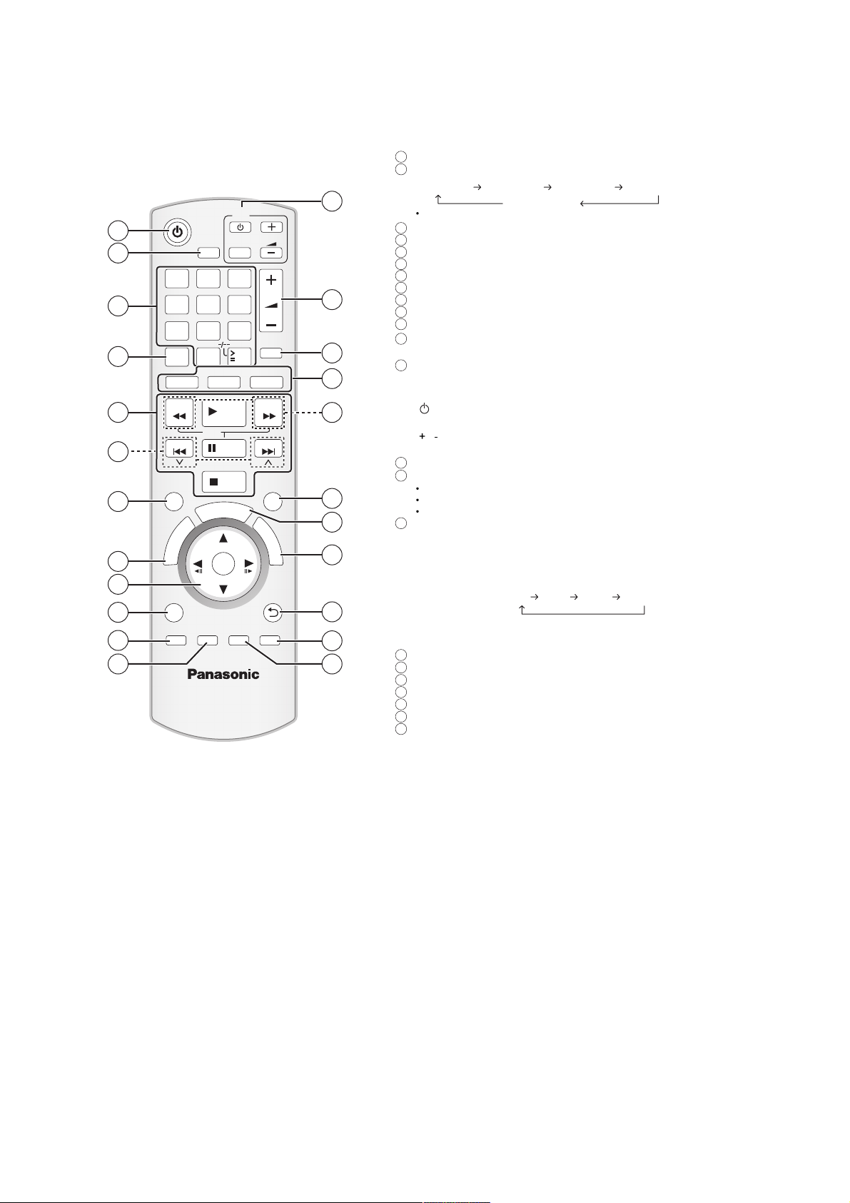
5 Location of Controls and Components
5.1. Remote Control Key Button Operations
Turn the main unit on/off
1
Set the Sleep timer
2
Press [SLEEP].
1
2
3
4
5
6
7
8
9
10
11
12
SLEEP
1 2 3
4 5 6
7 809
PLAY
MODE
REPEAT
-
DVD
SEARCH
SKIP
SURROUND
R
O
T
A
U
G
I
V
N
A
E
N
T
M
C
E
P
R
I
O
D
T
MENU
PLAY
LIST
MIC VOL
SETUP
-
CH SELECT
-
W.SRD
SLOW
T
S
USB
PLAY
PAUSE
STOP
R
A
T
OK
ECHO
-
FL DISPLAY
TV
AV
10
VOL
VOL
MUTE
RADIO
EXT-IN
SEARCH
SKIP
SOUND
F
U
N
C
T
I
O
N
S
RETURN
CANCEL
13
14
15
16
17
18
19
20
21
22
23
SLEEP 30 SLEEP 60 SLEEP 90 SLEEP120
To confirm the remaining time, press the button again.
3
Select channels and title numbers etc. / Enter numbers
4
Select the play mode / Set the repeat mode
5
Basic operations for play
6
Select preset radio stations
7
Select surround sound effects
8
Show a disc top menu or program list
9
Select or confirm menu items / Frame-by-frame
10
Show a disc menu or play list
11
Show setup menu or select speaker channel
12
Adjust the Microphone volume/ Turn Whisper-mode
Surround on/off
13
TV operations
Aim the remote control at the Panasonic TV and press the
button.
[ ]: Turn the TV on/off
[AV]: Change the TV s video input mode
[
, ]: Adjust the TV volume
This may not work properly with some models.
14
Adjust the volume of the main unit
15
Mute the sound
MUTE flashes on the main unit s display while the function is on.
To cancel, press the button again or adjust the volume.
Muting is cancelled when you switch the unit to standby.
16
Source select
[DVD]: Select disc as the source
[USB]: Select USB as the source
[RADIO], [EXT-IN]: Select FM tuner or external audio as the
*
(TV) will appear beside AUX or D-IN , indicating the TV audio
setting for VIERA Link HDAVI Control
17
Select radio stations manually
18
Select sound mode
19
Show START menu
20
Show on-screen menu
21
Return to previous screen
22
Cancel
23
Adjust the echo level / Switch information on the main unit s
display
OFF (Cancel)
source
FM AUX
*
D-IN*MUSIC P.
14
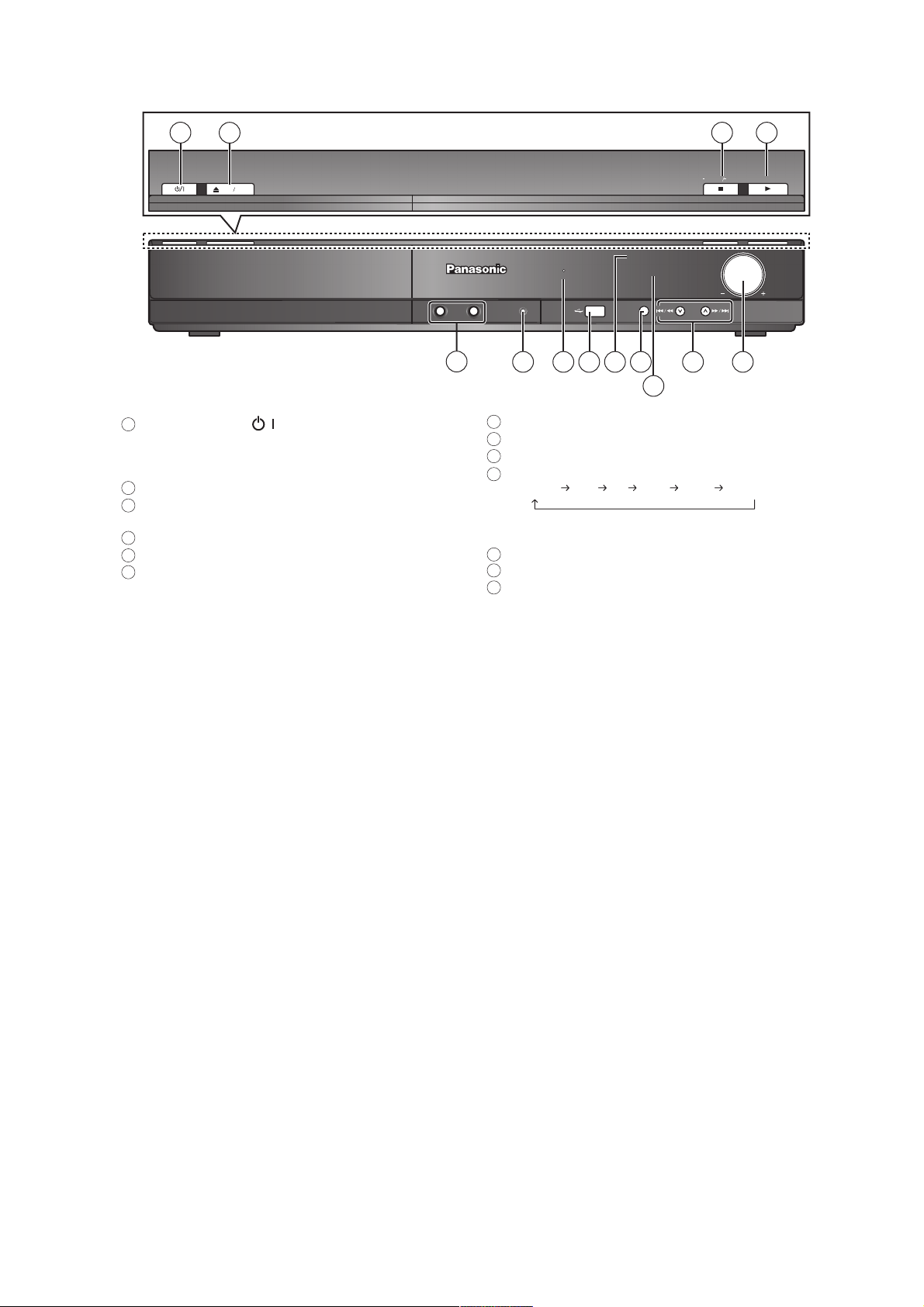
5.2. Main Unit Key Button Operations
1
1
Standby/on switch ( / )
2
OPEN CLOSE
Press to switch the unit from on to standby mode or vice
versa. In standby mode, the unit is still consuming a small
amount of power.
2
Open/Close the disc tray
3
Stop playing / Select the tuning mode / Adjust the FM
reception condition
4
Play discs / Memorize the receiving radio stations
5
Connect microphones
6
Connect external music device
1-MIC-2
3 4
TUNE MODE FM MODE
SURROUND OUTPUT
MUSIC PORT
5
76
SELECTOR
8 10
9
TUNE
12
MEMORY
VOLUME
13
11
7
The indicator lights when there is surround sound effect.
8
Connect USB device
9
Remote control signal sensor
10
Select the source
DVD/CD USB FM AUX
*
(TV) will appear beside AUX or D-IN , indicating the TV audio
setting for VIERA Link HDAVI Control
11
Display
12
Skip or slow-search play / Select the radio stations
Adjust the volume of the main unit
13
*
D-IN*MUSIC P.
15
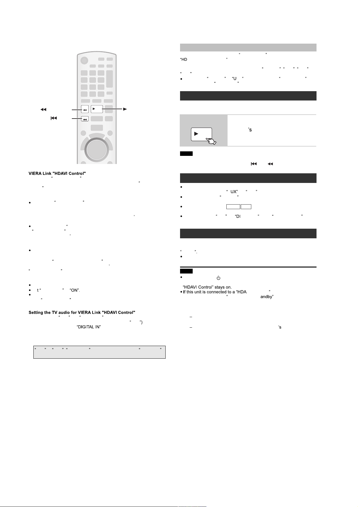
5.3. Using the VIERA Link “HDAVI Control”
Auto lip sync
(Available when using VIERA Link HDAVI Con trol wit h
AVI Control 3 (or later) co mp ati bl e TV)
This function automatically provides synchronised audio and video
output. (This works only when the source is
D-IN .)
When using
VIDEO menu to
One touch play
SEARCH
SEARCH
SKIP
VIERA Link HDAVI Control is a convenient function that offers linked
operations of this unit, and a Panasonic TV (VIERA) under
. You can use this function by connecting the equipment with the
Control
HDMI cable. See the operating instructions for connected equipment for
operational details.
VIERA Link
HDMI which is an industry standard known as HDMI CEC (Consumer
Electronics Control), is a unique function that we have developed and
added. As such, its operation with other manufacturers
supports HDMI CEC cannot be guaranteed.
This unit supports
HDAVI Control 4 is the newest standard (current as of December,
2008) for Panasonic
standard is compatible with Panasonic s conventional HDAVI
equipment.
Please refer to individual manuals for other manufacturers equipment
supporting VIERA Link function.
The TV with
operation: VIERA Link Control only with TV
HDAVI Control 2 (or later)]
Preparation
Confirm that the HDMI connection has been made .
Se
To complete and activate the connection correctly, turn on all VIERA
Link
corresponding HDMI input mode for this unit.
Select between AUX and DIGITAL IN to work with the linked operations.
Confirm the audio connection to the AUX terminal (for
OPTICAL IN terminal (for
Whenever the connection or settings are changed, reconfirm the points
above.
*
AUX or D-IN ( DIGITAL IN ) works depending on the TV AUDIO
setting
HDAVI Control , based on the control functions provided by
HDAVI Control 4 function.
s HDAVI Control compatible equipment. This
HDAVI Control 2 (or later) function enables the following
VIERA Link to
HDAVI Control compatible equipment and set the TV to the
PLAY
SKIP
s remote control [for
)
PLAY
HDAVI
equipment that
AUX or
You can turn on this unit and the TV, and start playing the disc with a
single press of a button.
During standby
mode
Note
Playback may not be immediately displayed on the TV. If you miss the
beginning portion of playback, press [ ] or [ ] to go back to where
playback started.
Auto input switching
When you switch the TV input to TV tuner mode, this unit will
automatically switch to
When this unit is in
input mode for this unit.
When playback stops (
will automatically return to TV tuner mode.
When you select
START menu , the TV will automatically switch to TV tuner mode.
Power off link
When the TV is turned off, this unit goes into standby mode automatically.
To continue audio playback even when the TV is turned off, select
VIDEO
When the TV is turned on, this unit does not turn on automatically.
(Power on link is not available.)
Note
When you press [ ], only this unit turns off. Other
connected equipment compatible with VIERA Link
compatible TV with the Intelligent Auto St setting
activated on the TV, this unit will be automatically turned
to standby under the following conditions:
e.g.,
when changing the TV input from the one this unit
is connected to
when changing the speaker use from this unit
speakers to the TV speakers
For details, refer also to the operating instructions for your
TV.
DVD/CD , USB , AUX or
DVD/CD or SB as the source, set TIME DELAY in
0 ms/AUTO
(Remote control only)
Start disc playback.
PLAY
This unit speakers will be
automatically activated
*
A
DVD/CD mode, the TV will automatically switch its
DVD-V
*
or
AUX
*
D-IN
or
VCD
GITAL IN
.
) or when this unit turns off, the TV
*
from
Input Selection in
VI Control 4
16
Speaker control VIERA Link Control only wi s remote control
[for
You can select whether audio is output from this unit s speakers or the TV
speakers by using the TV menu settings. For details, refer to the
operating instructions of your TV.
Home Cinema
This unit s speakers are active.
When this unit is in standby mode, changing the TV speakers to this
unit s speakers in the TV menu will automatically turn this unit on and
sele
AUX
*
or
*
as the source.
-IN
The TV speakers are automatically muted.
You can control the volume setting using the volume or mute button on
s remote control. (The volume level is displayed on the main
the TV
unit s display.)
To cancel muting, you can also use this unit
If you turn off this unit, TV speakers will be automatically activated.
TV
TV speakers are active.
The volume of this unit is set to
This function works only when D U A* or D-IN*is
selected as the source on this unit.
s remote control.
.
Audio output is 2-channel audio.
When switching between this unit speakers and TV speakers, the TV
screen may be blank for several seconds.
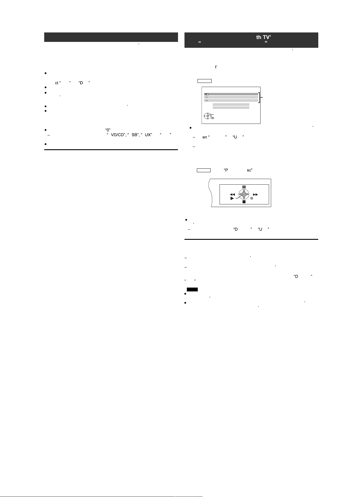
HDAVI Control 2 (or later) ]
You can control the playback menus of this unit with the TV
control. When operating the TV s remote control, refer to the below
illustration for operation buttons.
1 Select this uni s operation menu by using the TV menu settings.
(For details, refer to the operating instructions of your TV.)
The START menu will be shown.
e.g.
DVD-V
DVD/CD Home Cinema
Playback Disc
TOP MENU (DVD)
MENU (DVD)
Input Selection
Sound
OK
RETURN
The START menu can also be shown by using a button on the TV
remote control (e.g. [OPTION]).
Playback/menu access
Wh DVD/CD or SB is selected as the source, this works
only during stop mode.
This does not work while iPod music playback screen is displayed
on the TV.
2 Select the desired item on the START menu.
When the on-screen control panel appears
e.g. (when
DVD-V
layback Di is selected from the START menu.)
RETURN
s remote
s
You can operate the playback with the indicated controls.
The on-screen control panel can also be shown by using a button on the
s remote control (e.g. [OPTION]).
TV
This works only during VD/CD or SB playback and resume
modes or, while iPod music playback screen is displayed on the TV.
If the TV has automatically switched to the HDMI input mode for this
unit
The TV will automatically switch to TV tuner mode when:
you press [EXIT] button on the TV s remote control to exit VIERA Link
Control.
you press [EXIT] or [RETURN] button on the TV s remote control to exit
the START menu.
(This does not work during playback or resume mode when
VD/CD or
USB is selected as the source.)
Note
Depending on the menu, some button operations cannot be performed
from the TV
You cannot input numbers with the numbered buttons on the TV
remote control ([0] to [9]). Use this unit
s remote control.
s remote control to select the
s
play list etc.
17
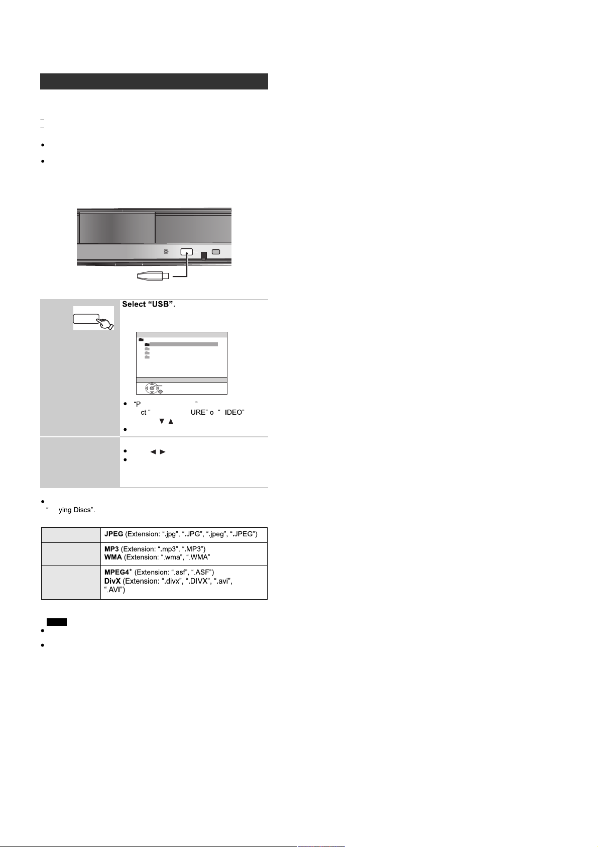
5.4. USB Connection and Operations
Playing from an USB device
You can connect and play tracks or files from USB mass storage class
devices.
Devices which are defined as USB mass storage class:
USB devices that support bulk only transfer.
USB devices that support USB 2.0 full speed.
Preparation
Before connecting any USB mass storage device to the unit, ensure
that the data stored therein has been backed up.
It is not recommended to use a USB extension cable. The USB device
connected using the cable will not recognised by this unit.
Connect the USB device (not included).
Main unit
USB device
1
2
Play starts from the selected content.
For other operating functions, they are similar to those described in
Pla
Supported Formats
Still pictures
Music
Video
USB
iPod
The menu screen appears.
e.g.
USB
ROOT
Songs
Concert_01
Concert_02
Southern_AI
OK
If
LAYBACK MENU screen appears,
AUDIO/PICT r V by
sele
pressing [ , ] and then [OK].
To display/exit the screen, press [MENU]
Select an item.
Press [ , ] to skip page by page.
To return to the previous screen, press
[RETURN]
.
*
For Panasonic D-Snap/DIGA
NOTE
Maximum: 255 folders (excluding Root folder), 4000
files, 28 characters for file/folder name.
Only one memory card will be selected when
connecting a multiport USB card reader. Typically the
first memory card inserted.
18
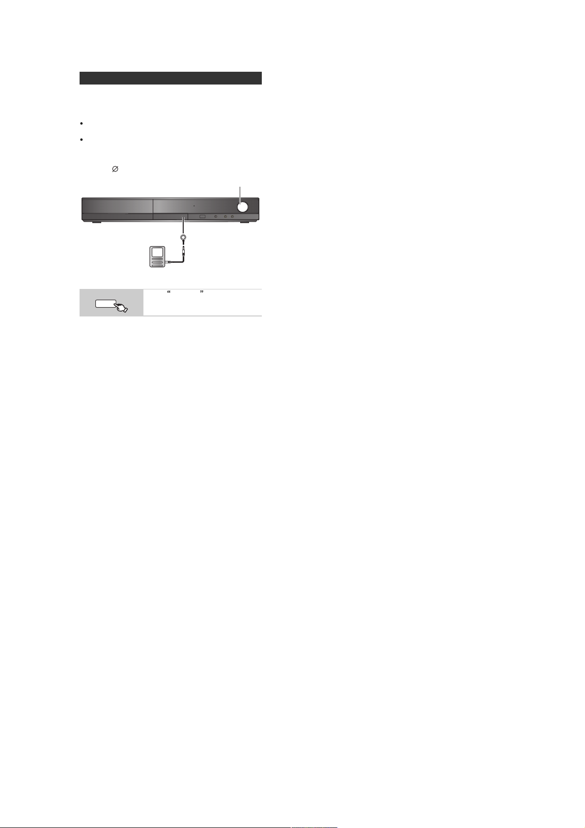
5.5. Music Port Connection and Operations
Playing from MUSIC PORT
The MUSIC PORT allows you to connect and enjoy music
from an external music device (e.g. MP3 player) through
your home theater system.
Preparation
To avoid distorted sound, make sure that any equalizer
function of your external device is turned off.
Reduce the volume of this unit and external music
device.
Connect the external music device (not included).
Plug type: 3.5 mm stereo mini plug
VOLUME
MUSIC PORT
External music device
Reduce the volume before connecting.
RADIO
EXT-IN
Adjust the volume on the external music device to a normal
listening level, and then adjust the volume of this unit.
Select MUSIC P. .
19
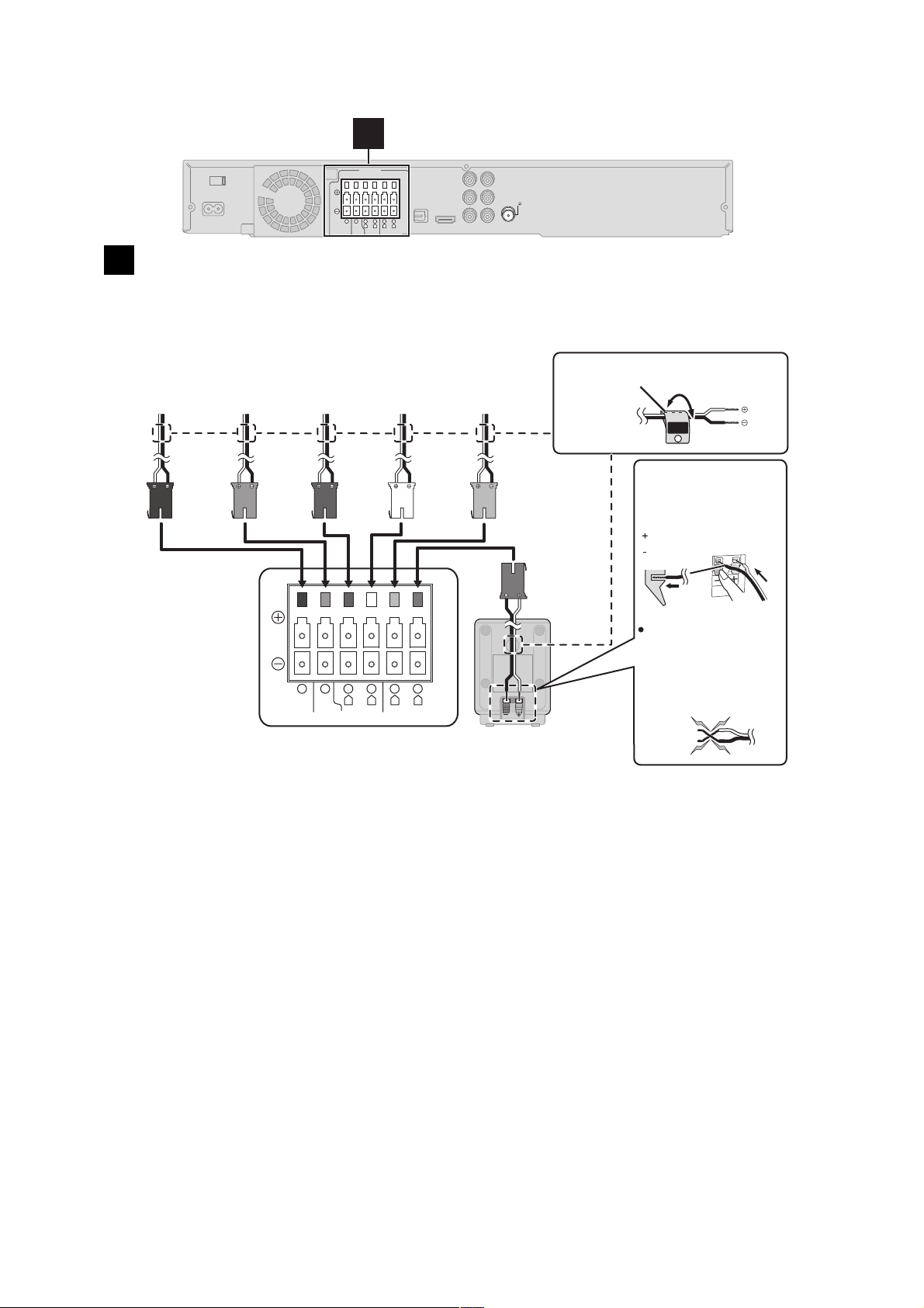
5.6. Speaker Connection
1
SPEAKERS
FM ANT
(75 )
6 5 2 1 4 3
R
LRL
CENTERSUBWOOFER FRONT
SURROUND
Speaker connections
1
Setup example
Pay attention to the type of speaker and the connector colour when you place the speakers.
Connect to the terminals of the same colour.
Use of the speaker cable stickers is convenient when making cable connections.
PURPLE
SUBWOOFER
GREEN
CENTER
Main unit
R
WHITE
FRONT
(L)
R
L
SURROUND
RED
FRONT
(R)
6 5 2 1 4 3
CENTERSUBWOOFER FRONT
GREY
SURROUND
(R)
L
e.g. Surround speaker (L)
Speaker cable sticker (included)
Insert the wire fully,
taking care not to
insert beyond the
wire insulation.
: White
: Blue
BLUE
SURROUND
(L)
Be careful not to
cross (short circuit)
or reverse the polarity
of the speaker wires
as doing so may
damage the speakers.
SURROUND
Lch
3
DO
NOT
Main unit
Push!
20
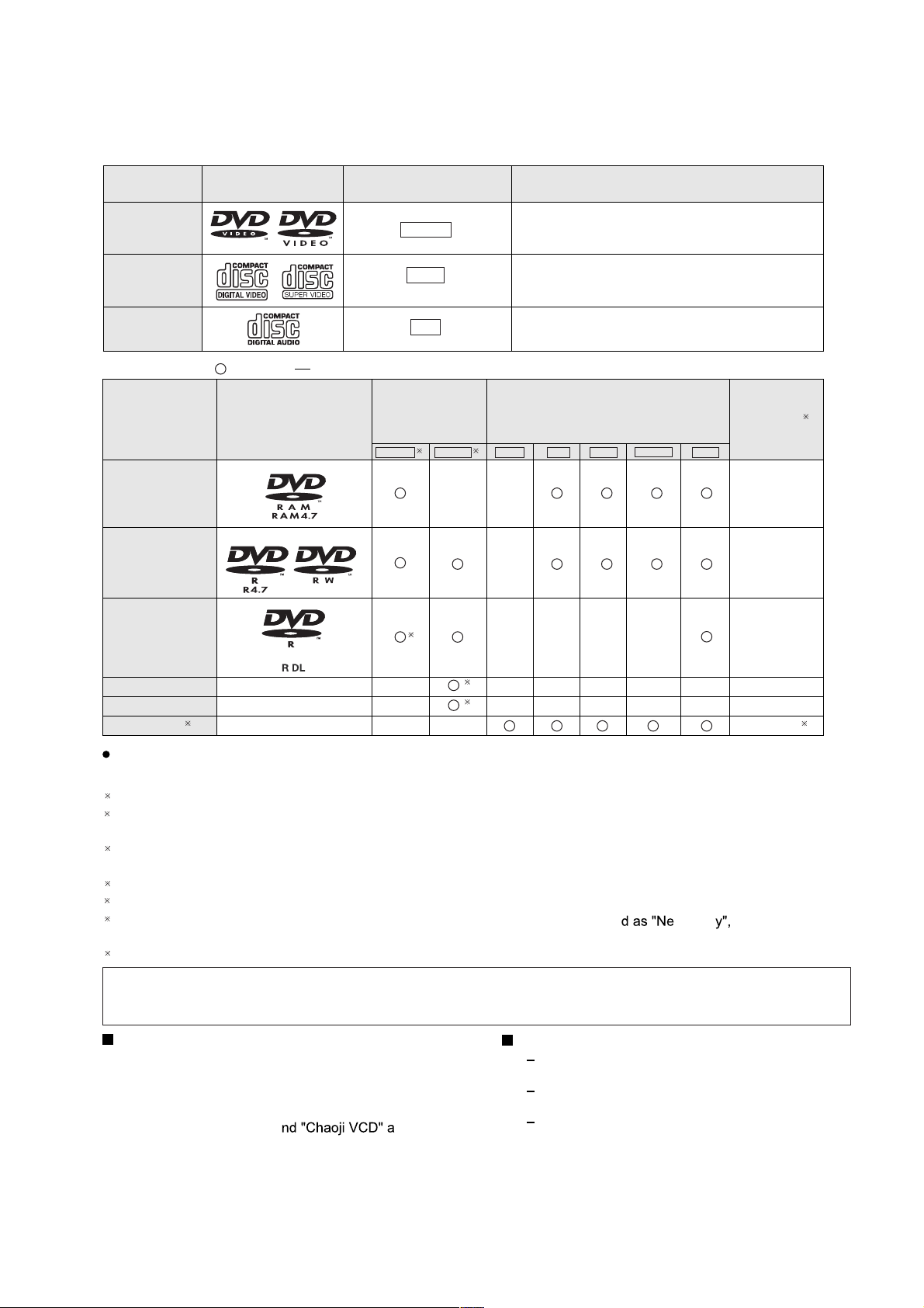
5.7. Disc Information
5.7.1. Disc Playability (Media)
Commercial discs
Disc Logo
Indicated in these
instructions by
Remarks
DVD-Video
Video CD
CD
Recorded discs ( : Playable,
Disc Logo
DVD-RAM
DVD-R/RW
DVD-R DL
: Not playable)
DVD-VR
DVD-V
VCD
CD
Recorded on a
DVD video
recorder, etc.
2
DVD-V
——
3
High quality movie and music discs
Music discs with video
Including SVCD (Conforming to IEC62107)
Music discs
Recorded on a personal
computer, etc.
4
WMA MP3 JPEG DivXMPEG4
—
——— —
Finalizing
Not necessary
Necessary
Necessary
6
+ R/++RW
+ R
DL
CD-R/RW
——() ——— — —
——() ——— — —
1
———
5
5
Necessary
Necessary
Necessary
7
It may not be possible to play all the above-mentioned discs in some cases due to the type of disc, the condition of
the recording, the recording method, or how the files were created. [Refer to Section 5.7.2. File Extension Type Support
1
This unit can play CD-R/RW recorded with CD-DA or Video CD format.
2
Discs recorded on DVD recorders or DVD video cameras, etc. using Version 1.1 of the Video Recording Format (a
unified video recording standard).
3
Discs recorded on DVD recorders or DVD video cameras using Version 1.2 of the Video Recording Format (a
WMA/MP3/JPEG/MPEG4/DIVX)]
unified video recording standard).
4
Discs recorded on DVD recorders or DVD video cameras using DVD-Video Format.
5
Recorded using a format different from DVD-Video Format, therefore some functions cannot be used.
6
A process that allows play on compatible equipment. To play a disc that is indicate
cessar the disc must
first be finalized on the device it was recorded on.
7
Closing the session will also work.
Note about using a DualDisc
The digital audio content side of a DualDisc does not meet the technical specifications of the Compact Disc Digital Audio
(CD-DA) format so playback may not be possible.
Discs that cannot be played
Blu-ray, HD DVD, AVCHD discs, DVD-RW version
1.0, DVD-Audio, DVD-ROM, CD-ROM, CDV, CD-G,
SACD, DivX Video Discs and Photo CD, DVD-RAM
that cannot be removed from their cartridge, 2.6 GB
and 5.2 GB DVD-RAM, a
on the market including CVD, DVCD and SVCD that
vailable
Video systems
This unit can play PAL and NTSC, but your TV must
match the system used on the disc.
PAL discs cannot be correctly viewed on an NTSC
TV.
This unit can convert NTSC signals to PAL 60 for
viewing on a PAL TV.
do not conform to IEC62107.
21
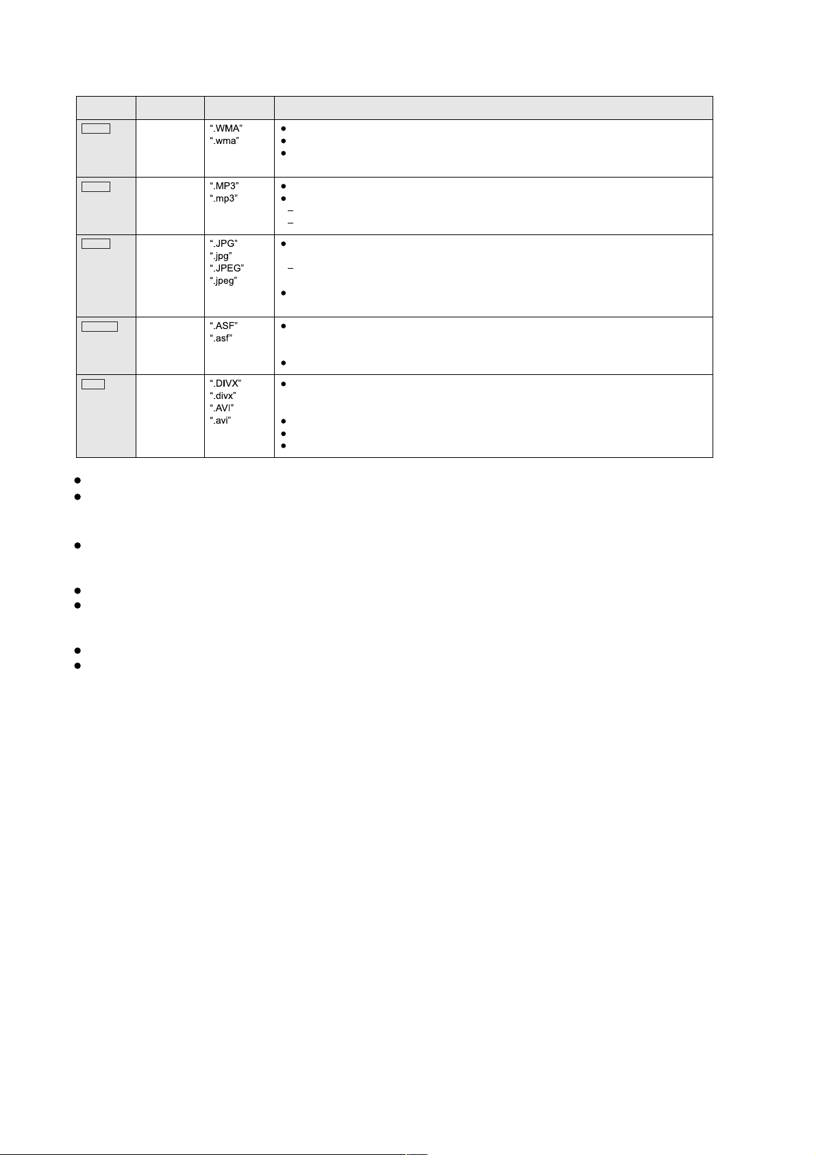
5.7.2. File Extension Type Support (WMA/MP3/JPEG/MPEG4/DivX)
Format Disc Extension Reference
WMA CD-R/RW Compatible compression rate: between 48 kbps and 320 kbps
MP3
JPEG
MPEG4
DivX
DVD-RAM
DVD-R/RW
CD-R/RW
DVD-RAM
DVD-R/RW
CD-R/RW
DVD-RAM
DVD-R/RW
CD-R/RW
DVD-RAM
DVD-R/RW
CD-R/RW
You cannot play WMA files that are copy-protected.
This unit does not support Multiple Bit Rate (MBR: an encoding process for audio content that
produces an audio file encoded at several different bit rates).
This unit does not support ID3 tags.
Sampling frequency and compression rate:
DVD-RAM, DVD-R/RW:
CD-R/RW: 8, 11.02, 12, 16, 22.05, 24 kHz (8 to 160 kbps), 32, 44.1 and 48 kHz (32 to 320 kbps)
JPEG files taken on a digital camera that conform to DCF Standard (Design rule for Camera File
system) Version 1.0 are displayed.
Files that have been altered, edited or saved with computer picture editing software may not be
displayed.
This unit cannot display moving pictures, MOTION JPEG and other such formats, still pictures other
than JPEG (e.g. TIFF), or play pictures with attached audio.
You can play MPEG4 data [conforming to SD VIDEO specifications (ASF standard)/MPEG4 (Simple
Profile) video system/G.726 audio system] recorded with Panasonic SD multi cameras or DVD
recorders with this unit.
The recording date may differ from that of the actual date.
Plays all versions of DivX
audio system] with standard playback of DivX
supported.
DivX files greater than 2 GB or have no index may not be played properly on this unit.
This unit supports all resolutions up to maximum of 720X480 (NTSC)/720 X576 (PAL).
You can select up to 8 types of audio and subtitles on this unit.
11.02, 12, 22.05, 24 kHz (8 to 160 kbps), 44.1 and 48 kHz (32 to 320 kbps)
fi
video (including DivXfi6) [DivX video system/MP3, Dolby Digital or MPEG
fi
media files. Functions added with DivX Ultra are not
There may be differences in the display order on the menu screen and computer screen.
This unit cannot play files recorded using packet write.
DVD-RAM
Discs must conform to UDF 2.0.
DVD-R/RW
Discs must conform to UDF bridge (UDF 1.02/ISO9660).
This unit does not support multi-session. Only the default session is played.
CD-R/RW
Discs must conform to ISO9660 level 1 or 2 (except for extended formats).
This unit supports multi-session but if there are many sessions it takes more time for play to start. Keep the number
of sessions to a minimum to avoid this.
22
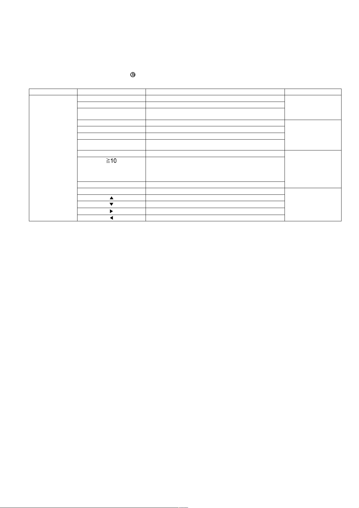
6 Self-Diagnosis and Special Mode Setting
6.1. Service Mode Summary Table
The service modes can be activated by pressing various button combination on the main unit and remote control unit.
Below is the summary for the various modes for checking:
In order to enter the service mode, press [ ] RETURN button on remote control.
Main unit buttons Remote control unit buttons Application Note
[STOP] [0] Error code check. (Refer to the section
[5] Jitter checking.
[PAUSE] Initial setting of laser drive current.
[FUNCTIONS] DVD laser drive current check. (Refer to the section
[3] CD laser drive current check.
[6] Region display and mode.
[SOUND] CPPM/CRM keys check.
[7] Micro-processor firmware version check. (Refer to the section
[]
[OK] DVD Module P.C.B. reset.
[8] DVD Module P.C.B. firmware version check. (Refer to the section
[] Timer 1 check.
[]
[]
[] Timer 2 reset.
Initialization of the player (factory setting is restored).
Used after replacement of Micro-processor (DV5 LSI) IC, FLASH
ROM IC (IC8651), EEPROM IC (IC8611) and DVD Module
P.C.B.
Timer 1 reset.
Timer 2 check.
“6.2.1. Service Mode
Table 1” for more information.)
“6.2.2. Service Mode
Table 2” for more information.)
“6.2.3. Service Mode
Table 3“for more information.)
“6.2.4. Service Mode
Table 4“for more information.)
Note:
An error code will be canceled if a power supply is turned OFF.
*1: CPPM is the copy guard function beforehand written in the disk for protection of copyrights.
*2: CEC is the consumer electronic control used for high-level user control of HDMI-connected devices.
*3: HDCP is the specification developed to control digital audio & video contents transmission for DVI or HDMI connections.
6.2. Service Mode Table
By pressing various button combinations on the main unit and remote control unit, you can activate the various service modes fo r
checking.
Special Note:
• Due to the limitations of the no. characters that can be shown on the FL Display, the “FL Display” button on the remote control
unit can be used to show the two display pages. (Display 1 / Display 2).
• Refer to Section 5.1 for the section on “Remote Control Key Buttons Operations”.
23
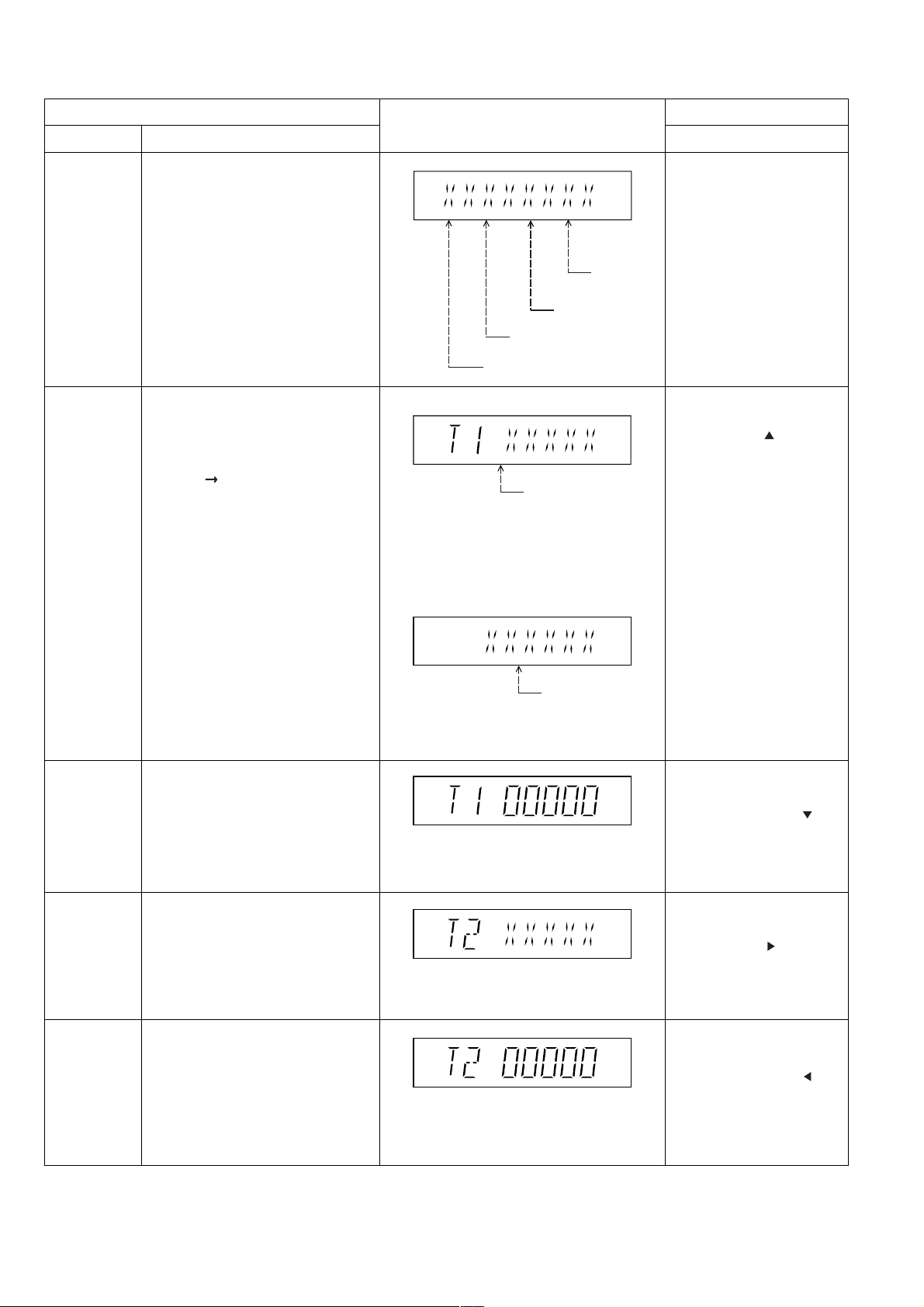
6.2.1. Service Mode Table 1
Error code
check
Jitter check
Item
DescriptionMode Name
Error code check
The latest error code stored in the
EEPROM IC is displayed.
Note: Refer to "Section 6.5 DVD Self
Diagnostic Function-Error Code" for
more detailed information on the error
codes.
Jitter check.
Jitter rate is measured and displayed.
Measurement is repeatedly done in
the cycle of one second. Read error
counter starts from zero upon mode
setting.
When target block data failed to be
read out, the counter advances by one
increment. When the failure is caused
by minor error, it may be corrected
when retried to enable successful
reading.
In this case, the counter advances by
one. When the error persists even
after retry, the counter may jump by
two or more.
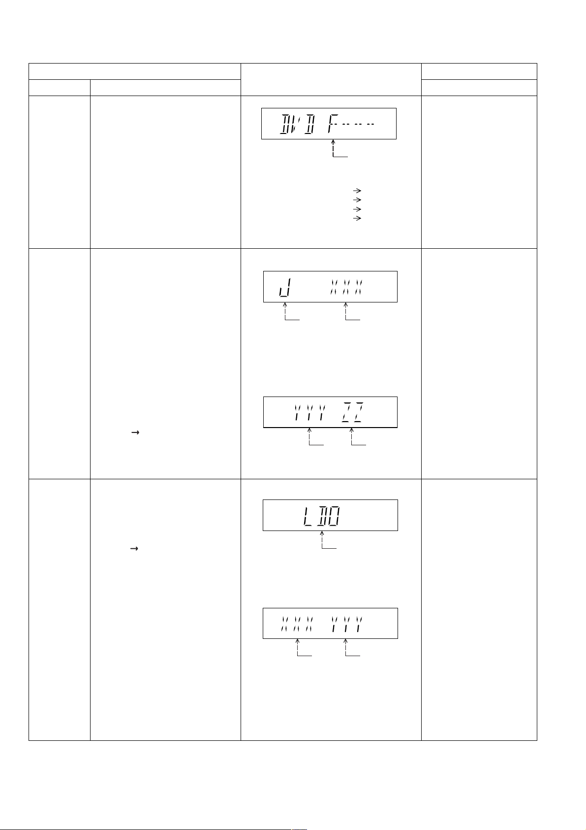
FL Display sequence:
Display 1 2.
FL Display
F / H / U
Error code (play_err) is expressed in the
following convention.
Error code = 0 x DAXX is expressed: DVDnn U12
Error code = 0 x DBXX is expressed: DVDnn H12
Error code = 0 x DXXX is expressed: DVDnn F123
Error code = 0 x 0000 is expressed: DVDnn F--* "xx" denotes the error code
(Display 1)
Jitter check
mode
Jitter rate is shown in decimal notation to one
place of decimal.
Focus drive value is shown in hexadecimal
notation.
(Display 2)
Lead
Error
Counter
Jitter rate
Focus Drive
Value
Key Operation
Front Key
In STOP (no disc) mode,
press [STOP] button on the
main unit, and [0] button on
the remote control unit. *With
pointing of cursor up and
down on display.
Cancelled automatically
5 seconds later.
To exit, press [POWER]
button on main unit or
remote control.
In STOP (with disc inside
tray) mode, press [STOP]
button on the main unit,
and [5] button on
the remote control unit,
after Display 1 appears,
then press [PLAY].
Press [POWER] or [STOP]
button to exit.
Press [FL Display] on
remote control unit for next
page (FL Display).
Initial setting of
laser drive
current
Initial setting of laser drive current.
Initial current value for the DVD laser
and CD laser is separately saved in
the EEPROM IC.
FL Display sequence:
Display 1 2.
(Display 1)
Laser current
measurement
mode
The value denotes the current in decimal
notation.
(Display 2)
CD
Laser
The above example shows the initial current
is XXXmA and YYYmA for CD laser and
DVD laser respectively when the laser is
switched on.
DVD Laser
In STOP (no disc) mode,
press [STOP] button on the
main unit, and [PAUSE]
button on the remote
control unit.
Cancelled automatically
5 seconds later.
Press [FL Display] on
remote control unit for next
page (FL Display) on values
of laser drive current.
24
6.2.2. Service Mode Table 2
DVD laser
drive current
measurement
CD laser drive
current
measurement
Item
DescriptionMode Name
DVD laser drive current measurement.
DVD laser drive current is measured
and the result is displayed together
with the initial value stored in the
EEPROM IC.
After the measurement, DVD laser
emission is kept on. It is turned off
when POWER key is switched off.
FL Display sequence:
Display 1 2.
CD laser drive current measurement.
CD laser drive current is measured
and the result is displayed together
with the initial value stored in the
EEPROM IC.
After the measurement, CD laser
emission is kept on. It is turned off
when POWER key is switched off.
FL Display sequence:
Display 1 2.
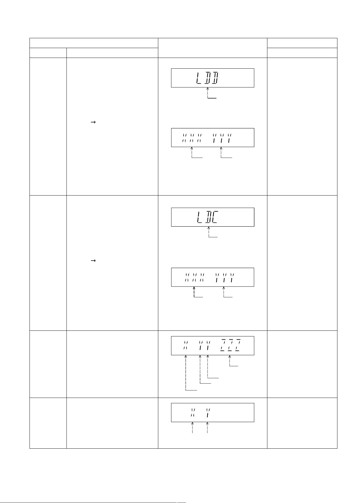
FL Display
(Display 1)
DVD laser current
measurement mode
The value denotes the current in decimal
notation.
(Display 2)
DVD
Laser
Initial Value
The above example shows the initial current
is XXXmA and the measured value is
YYYmA.
(Display 1)
The value denotes the current in decimal
notation.
(Display 2)
DVD
Laser
Value
CD laser current
measurement mode
Key Operation
Front Key
In STOP (no disc) mode,
press [STOP] button on the
main unit, and
[FUNCTIONS] button on
the remote control unit.
Cancelled automatically
5 seconds later.
Press [FL Display] on
remote control unit for next
page (FL Display) on values
of dvd drive current.
In STOP (no disc) mode,
press [STOP] button on
the main unit, and [3]
button on the remote
control unit.
Cancelled automatically
5 seconds later.
Press [FL Display] on
remote control unit for next
page. (FL Display)
Region display
CPPM/CRM
Keys Check
Region code display, TV broadcasting
system & the model no. information.
Note: Refer to Figure 6.1 for "Video
Design Information".
CPPM/CRM refers to the Content
Protection for Recordable Media and
Pre-Recorded Media. It displays the
existence of the keys as "1" or "0".
OK: Existing of keys.
NG: Non existing of keys.
CD
laser initial
value
The above example shows the initial current is
XXXmA and the measured value is YYYmA.
N: no PAL / P: PAL
Region No.: 0-8
0: NG
0: NG
1: OK
1: OK
CD laser
value
Model
No.
Information
N: NTSC / 6: PAL60
In STOP (no disc)
mode, press [STOP]
button on the main unit,
and [6] button on the
remote control unit.
Cancelled automatically
5 seconds later.
In STOP (no disc)
mode, press [STOP]
button on the main unit,
and [SOUND] button on
the remote control unit.
Cancelled automatically
5 seconds later.
25
Product
OSD
Default
English
Japanese
English
English
English
English
English
English
English
English
OSD Menu Language
English, Spanish,
Canadian, French
English, French, German,
Spanish, Polish, Russian,
Czech, Hungarian
English, French, German,
Italian, Spanish, Polish,
Swedish, Dutch
English, French, German,
Spanish, Polish, Russian,
Czech, Hungarian
English, Traditional Chinese
English, French, German,
Italian, Spanish, Polish,
Swedish, Dutch
English, Spanish, French,
Brazilian Portuguese
English, French, German,
Spanish, Polish, Russian,
Czech, Hungarian
Code
1
2
2
2
2
3
4
4
5
6
TV Broadcasting
System
NTSC
NTSC
PAL
PAL
PAL
PAL
NTSC
PAL
NTSC
SECAM
PAL
Signal System
(Default)
NTSC (*A)
NTSC (*A)
PAL (*C)
PAL (*C)
PAL (*C)
NTSC (*B)
PAL (*C)
NTSC (*D)
PAL (*C)
NTSC (*B)
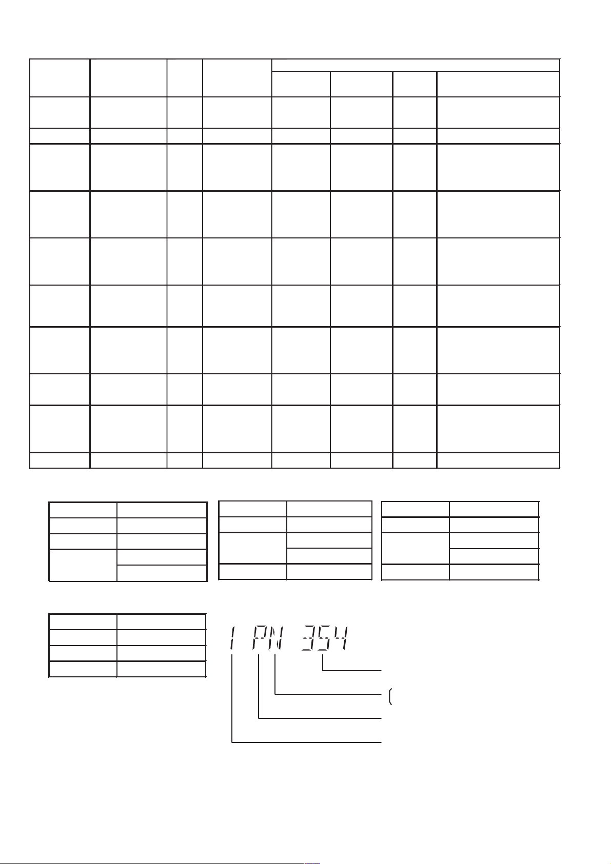
Region Display
(Default)
1PN
2PN
2P6
2P6
2P6
3PN
4P6
4PN
5P6
6PN
Model Series
P, PC, PX
(S) Japanese, English
EP
EB, EG
GC, GS
GA, GD,
GT, GJ
GN
PN, PH, PU,
PR
EE
GK English, Simplified Chinese
Country Region
USA, Canada, PX
Japan
Europe
Europe
Middle East
Hong Kong,
South East Asia,
Thailand, Korea,
Taiwan
New Zealand,
Australia
Central/South/
Latin America
CIS
China
Region
NTSC (*A)
Source Output
Screen Saver NTSC
NTSC disc NTSC
PAL disc
NTSC (*D)
Source Output
Screen Saver NTSC
NTSC disc NTSC
PAL disc NTSC
PAL (DVD-V)
NTSC (DVD-A/VCD)
NTSC (*B)
Source Output
Screen Saver NTSC
NTSC disc
PAL disc PAL
Explanation of Display
NTSC (default)
PAL60
Figure 6.1 Video Design Information
PAL (*C)
Source Output
Screen Saver PAL
NTSC disc
PAL disc PAL
Individual Model Code
N: If NTSC disc is played, NTSC output.
6: If NTSC disc is played, PAL60 output.
Can play PAL disc
Region code
PAL60 (default)
NTSC
26
6.2.3. Service Mode Table 3
Micro-processor
firmware version
display &
EEPROM
checksum
display.
Item
DescriptionModel Name
Micro-processor firmware version
display & EEPROM checksum display.
EEPROM checksum is only available
due to existence of EEPROM IC.
Note: Condition 1/2/3 shows the state
of EEPROM IC.
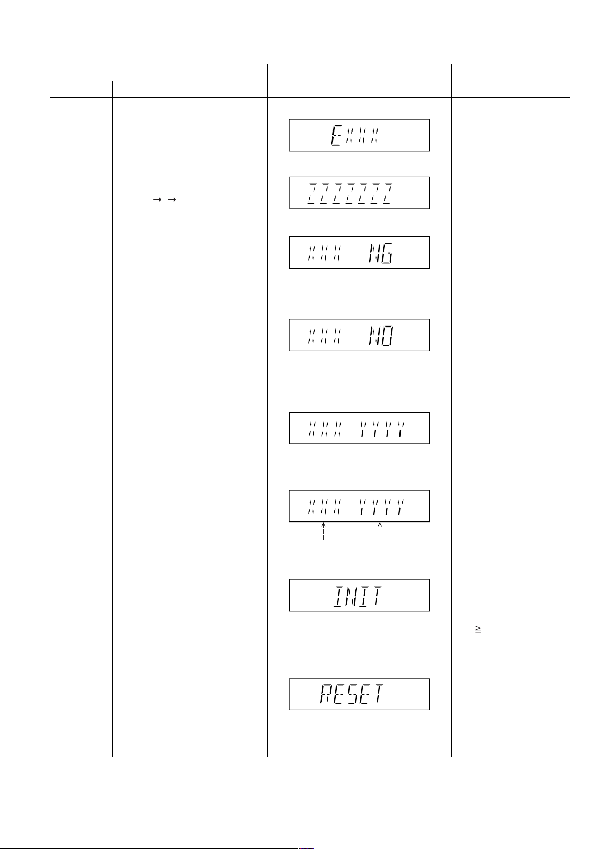
FL Display sequence:
Display 1 2 3.
FL Display
(Display 1)
(Display 2)
(Condition 1)
If the version of the EEPROM does not match,
[NG] is displayed.
(Condition 2)
(a) If there is NO EEPROM header string
OR
(b) If there is no EEPROM (no data is received
by Micro-processor), [NO] is displayed.
(Condition 3)
Key Operation
Front Key
In STOP (no disc)
mode, press [STOP]
button on the main unit,
and [7] button on the
remote control unit.
Cancelled automatically
5 seconds later.
Initialization
DVD
Module P.C.B.
Reset
Initialization.
User settings are cancelled and player
is initialized to factory setting.
It is necessary when after replacement
of Micro-processor (DV5 LSI) IC,
FLASH ROM IC (IC8651), EEPROM
IC (IC8611) & DVD Module P.C.B.
To reset DVD Module P.C.B.
This process is used when the DVD
Module P.C.B. or FLASH ROM
IC is replaced with a new one.
If the EEPROM version matches, checksum
[YYYY] is displayed.
(Display 3)
Opecon
Version
EEPROM
Checksum
(If applicable,
refer below.)
Press [FL Display] button on
remote control unit for next
page. (FL Display)
Press ’RETURN’ button on
remote control.
In STOP (no disc)
mode, press [STOP]
button on the main unit,
and [ 10] button on the
remote control unit.
Cancelled automatically
3 seconds later.
While in initialization
mode, press & hold
[STOP] button on the main
unit, follow by [OK] button
on the remote control unit.
Cancelled automatically
5 seconds later.
27
6.2.4. Service Mode Table 4
DVD
Module P.C.B.
firmware
version display
Timer 1 check
Item
DescriptionMode Name
DVD Module P.C.B. firmware version is
displayed on the FL Display.
The firmware version can be updated
using recovery disc.
Note: It is necessary to check for
firmware version before carrying out
the version up using the disc.
Timer 1 check
Laser operation timer is measured
separately for DVD laser and CD laser.
FL Display sequence:
Display 1 2.
FL Display
System
controller
version
Destination
System controller
generation
Region No.: 0-8
(Display 1)
DVD laser usage time
Shown to the above is DVD laser usage
time, and to the below is CD laser usage
time.
Time is shown in 5 digits of decimal notation
in a unit of 10 hours.
"00000" will follow "99999". (DVD laser)
(Display 2)
Key Operation
Front Key
In STOP (no disc)
mode, press [STOP]
button on the main unit,
and [8] button on the
remote control unit.
Cancelled automatically
5 seconds later.
In STOP (no disc) mode,
press [STOP] button on the
main unit, and [ ] button
on the remote control unit.
Cancelled automatically
3 seconds later.
Press [FL Display] button for
next page of FL Display.
Timer 1 reset
Timer 2 check
Timer 2 reset
Timer 1 reset
Laser operation timer of both DVD
laser and CD laser is reset all at once.
Timer 2 check
Spindle motor operation timer
Timer 2 reset
Spindle motor operation timer
CD laser usage time
Time is shown in 6 digits of decimal notation
in a unit of 10 hours.
"000000" will follow "999999". (CD laser)
Time is shown in 5 digits of decimal notation
in a unit of 10 hours.
It will clear to "00000" upon reset.
Time is shown in 5 digits of decimal notation in
a unit of 1 hour.
"00000" will follow "99999".
Time is shown in 5 digits of decimal notation in
a unit of 1 hour.
It will be cleared to "00000" upon activating
this.
While displaying Timer 1
data, press [STOP] button
on the main unit, and [ ]
button on the remote control
unit.
Cancelled automatically
5 seconds later
In STOP (no disc) mode,
press [STOP] button on the
main unit, and [ ] button
on the remote control unit.
Cancelled automatically
5 seconds later.
While displaying Timer 2
data, press [STOP] button
on the main unit, and [ ]
button on the remote
control unit.
Cancelled automatically
5 seconds later.
28
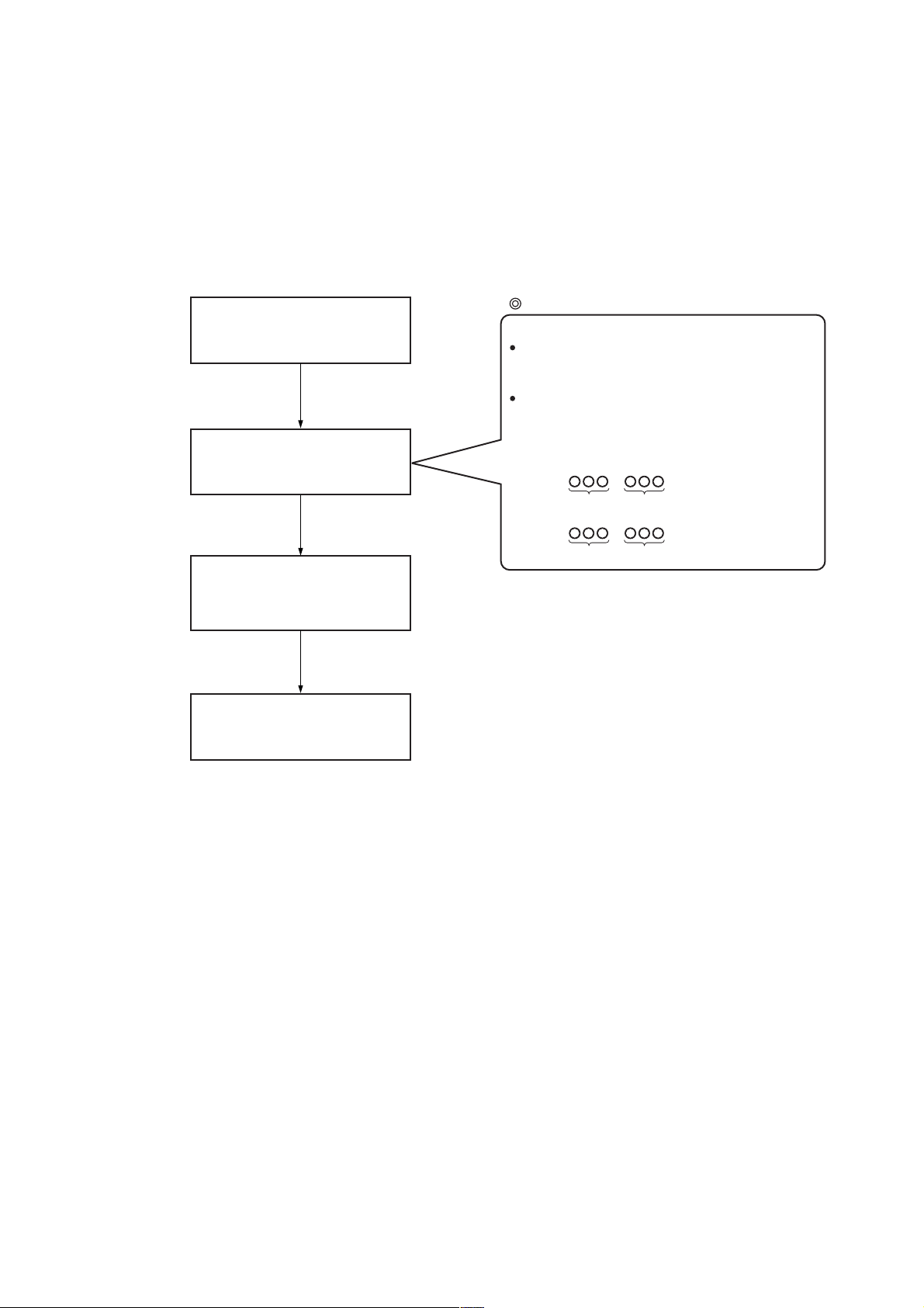
6.2.5. Optical Pick-up Self-Diagnosis
The optical pickup self-diagnosis function and tilt adjustment check function have been included in this unit. When repairing, use the
following procedure for effective self-diagnosis and tilt adjustment. Be sure to use the self-diagnosis function before replaci ng the
optical pickup when “NO DISC” is displayed. As a guideline, you should replace the optical pickup when the value of the laser drive
current is more than the specified value.
Note:
Press the power button to turn on the power, and check the value within three minutes before the unit warms up. (Otherwise, the
result will be incorrect.)
"NO DISC" is displayed, unit
does not play smoothly, etc.
Check the laser drive current.
Value is more than
37 (DVD), 41 (CD).
Replace the traverse unit.
(Refer to the section "OPTICAL
PICKUP REPLACEMENT
PROCEDURE" in this Guide.)
Initialize the main unit.
Use the optical pickup self-diagnosis function.
Method: With no disc in the main unit:
• Press the "FUNCTIONS" button on the remote
control unit while pressing the "STOP"
button on the main unit. (DVD)
•Press the "3" button on the remote
control unit while pressing the "STOP"
button on the main unit. (CD)
[Display content (display1/display2)]
/
LDD (DVD)
Factory setting Present value
LDC (CD)
/
Factory setting Present value
Replace with a new optical pickup if the present
value is more than 37 (DVD), 41 (CD).
Cause: Damage due to static electricity
during replacement.
29
6.3. DVD Self Diagnostic Function-Error Code
Remarks
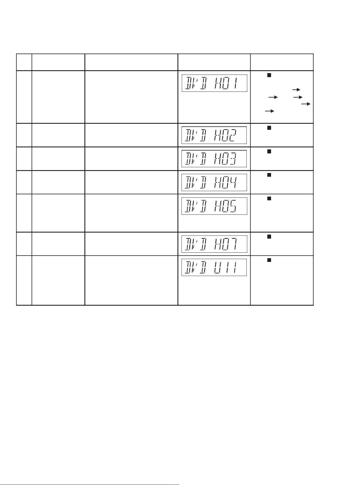
6.3.1. Mechanism Error Code Table
Error
Code
H01 Tray loading error The tray opening and closing is abnormal. Press [ STOP] on main
H02 Spindle servo error The spindle servo/motor is abnormal. The Press [ STOP] on main
H03 Traverse servo error The traverse is abnormal. (Traverse servo, Press [ STOP] on main
H04 Tracking servo error Tracking coil NG (OPU unit abnormal), Press [ STOP] on main
H05 Seek time out error It is not possible to access the disc. TOC Press [ STOP] on main
Diagnosis Contents
Description of error Automatic FL Display
CLOSE and OPEN of the tray cannot be unit for next error.
carried out properly. Loading motor error, (OPEN time: OPEN
DV5 LSI IC (IC8001) error. CLOSE OPEN
H01 at CLOSE: CLOSE
OPEN CLOSE H01)
FG pulse is abnormal. CLV servo error. unit for next error.
DV5 LSI IC (IC8001), TRV motor error.) unit for next error.
DV5 LSI IC (IC8001) error. unit for next error.
cannot read. Abnormal disc etc. Pickup unit for next error.
abnormal or disk is dirty. (TRV motor
error, DV5 LSI IC (IC8001) error.)
H07 Driver IC thermal shut The spindle motor is abnormal. Press [ STOP] on main
down (short between brushes) unit for next error.
U11 Focus servo error Focus coil, FE signal error. Disc may be Press [ STOP] on main
dirty. unit for next error.
(Unfinalized DVD-R
is likely to become
U11.)
30
 Loading...