

Panasonic SAPT-150-GC, SAPT-150-GCP, SAPT-150-GCT, SAPT-150-GS, SAPT-150-GCS Service manual
ORDER NO. MD0705010CE
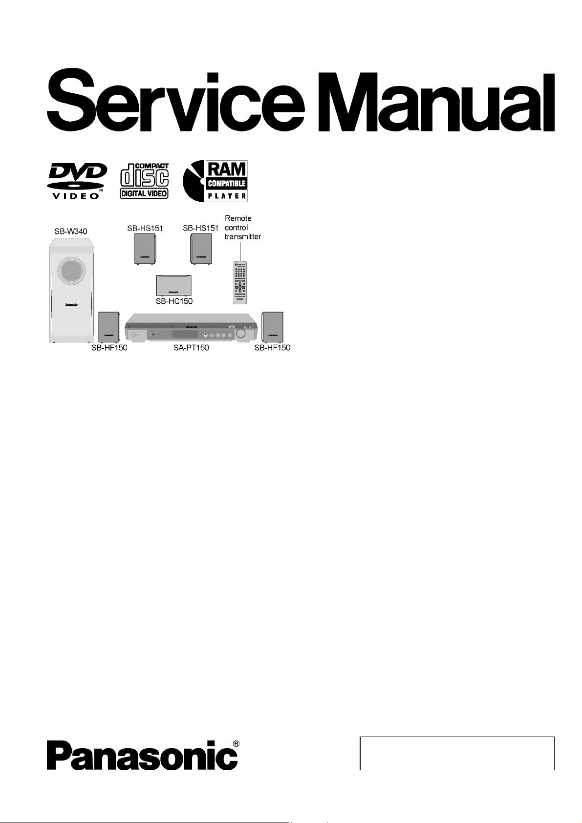
DVD Home Theater Sound System
SA-PT150GC
SA-PT150GCP
SA-PT150GCS
SA-PT150GCT
SA-PT150GS
Colour
(S).......................Silver Type
Specifications
lGENERAL
Power Supply: AC 110 to 240 V, 50/60 Hz
Power Consumption: Main unit 105 W
Power Consumption in Standby Mode:
approx. 1 W
Dimensions (W×H×D):
Mass: Main unit 3 kg
Operating Temperature Range: +5°C to +35°C
Operating Humidity Range: 5% to 90% RH (no
lAMPLIFIER SECTION
RMS Output Power: Dolby Digital Mode
lTotal RMS Dolby Digital mode power:
At 1 kHz and total harmonic of 10%
lFront Ch: 55 W / Channel (5 Ω)
lCenter Ch: 55 W / Channel (5 Ω)
lSurround Ch: 55 W / Channel (5 Ω)
At 100 Hz and total harmonic of 10%
lSubwoofer Ch: 55 W / Channel (5 Ω)
PMPO Output Power: 2800 W
DIN Output Power: Dolby Digital Mode:
lTotal DIN Dolby Digital mode power:
At 1 kHz and total harmonic of 1%
430×60×342 mm
condensation)
330 W
150 W
lFront Ch: 25 W / Channel (5 Ω)
lCenter Ch: 25 W / Channel (5 Ω)
lSurround Ch: 25 W / Channel (5 Ω)
At 100 Hz and total harmonic of 1%
lSubwoofer Ch: 25 W / Channel (5 Ω)
lFM TUNER, TERMINALS SECTION
Preset Memory: FM 30 stations
Frequency Modulation (FM)
Frequency range: 87.50-108.00 MHz
(50-kHz step)
Sensitivity: 1.8 µV (IHF)
S/N 26 dB: 1.4 µV
Antenna terminals: 75 Ω (unbalanced)
Mic Jack:
Sensitivity:
Terminal: Mono, 6.3 mm jack (1 system)
lUSB SECTION
USB Port:
USB standard: USB 2.0 full speed
Media file format support: MP3 (*.mp3)
0.7 mV (1.2 kΩ)
WMA (*.wma)
JPEG (*.Jpg, *.JPEG)
MPEG4 (*.asf)
© 2007 Matsushita Electric Industrial Co., Ltd. All
rights reserved. Unauthorized copying and
distribution is a violation of law.
V
V
SA-PT150GC / SA-PT150G CP / SA-PT150GCS / SA-PT150G CT / SA-PT150GS
USB device file system: FAT12
FAT16
FAT32
USB Port power: 500 mA (Max)
lDISC SECTION
Discs played (8 cm or 12 cm):
(1) DVD [DVD-Video, DivX (*1, *2)]
(2) DVD-RAM [DVD-VR, MP3 (*2, *6), JPEG (*2, *3), MPEG4
(*2, *4), DivX (*1, *2)]
(3) DVD-R [DVD-Video, DVD-VR, MP3 (*2, *6), JPEG (*2, *3),
MPEG4 (*2, *4), DivX (*1, *2)]
(4) DVD-R DL [DVD-Video, DVD-VR]
(5) DVD-RW [DVD-Video, DVD-VR, MP3 (*2, *6), JPEG (*2, *3),
MPEG4 (*2, *4), DivX (*1, *2)]
(6) +R/+RW [Video]
(7) +R DL [Video]
(8) CD, CD-R/RW [CD-DA, Video CD, SVCD (*5), MP3 (*2, *6),
WMA (*2, *7), JPEG (*2, *3), MPEG4 (*2, *4), DivX (*1, *2)]
*1 Plays all versions of DivX® video (including DivX®6) with
standard playback of DivX® media files. Certified to the DivX
Home Theater Profile.
*2 The total combined maximum number of recognizable audio,
picture and video contents and groups: 4000 audio, picture
and video contents and 400 groups.
*3 Exif Ver 2.1 JPEG Baseline files
lPicture resolution: between 160 x 120 and 6144 x 4096
pixels (Sub sampling is 4:0:0, 4:2:0, 4:2:2, or 4:4:4).
Extremely long and narrow pictures may not be displayed.
*4 MPEG4 data recorded with the Panasonic SD multi cameras
or DVD video recorders.
lConforming to SD VIDEO specifications (ASF standard)/
MPEG4 (Simple Profile) video system/G.726 audio system.
*5 Conforming to IEC62107
*6 MPEG-1 Layer 3, MPEG-2 Layer 3
*7 Windows Media Audio Ver.9.0 L3
lNot compatible with Multiple Bit Rate (MBR)
Pick Up:
Wavelength:
lCD: 785 nm
lDVD: 662 nm
Laser power:
lCD: CLASS 1M
lDVD: CLASS 1
Audio Output (Disc):
Number of channels: 5.1 ch (FL, FR, C, SL, SR,
SW)
lVIDEO SECTION
ideo system:(
GC/GCS/GCT/GS)
PAL 625/50, PAL 525/60,
NTSC
ideo system: (GCP) NTSC
Composite Video Output:
lOutput level: 1 Vp-p (75 Ω)
lTerminal: Pin jack (1 system)
Component video output: [NTSC: 480p/480i, PAL:576p/576i]
lY output level: 1 Vp-p (75 Ω)
lPBoutput level: 0.7 Vp-p (75 Ω)
lPRoutput level: 0.7 Vp-p (75 Ω)
lTerminal: Pin jack (Y: green, PB: blue,
P
: red) (1 system)
R
Note:
1. Specifications are subject to change without notice.
Mass and dimensions are approximate.
2. Total harmonic distortion is measured by the digital spectrum
analyzer.
Solder:
This model uses lead free solder (PbF).
Mechanism:
This model uses DL2S (Single tray) mechanism.
Power Supply:
This unit uses Switching Mode Power Supply (SMPS).
Refer to their respective original service manuals for *1, *2,
*3, *4.
2
SA-PT150GC / SA-PT150G CP / SA-PT150GCS / SA-PT150G CT / SA-PT150GS
CONTENTS
Page Page
1 Safety Precautions 5
1.1. GENERAL GUIDELINES
5
1.2. Before Repair and Adjustment (Using SMPS Module
P.C.B.)
1.3. Protection Circuitry
3
5
5

SA-PT150GC / SA-PT150G CP / SA-PT150GCS / SA-PT150G CT / SA-PT150GS
1.4. Safety Parts Information 6
1.5. Caution for AC Cord
2 Prevention of Electro Static Discharge (ESD) to
Electrostatically Sensitive (ES) Devices
3 Precaution of Laser Diode
4 About Lead Free Solder (PbF)
4.1. Service caution based on legal restrictions
5 Handling Precaution s for Traverse Unit
5.1. Cautions to Be Taken in Handling the Optical Pickup Unit
5.2. Grounding for electrostatic breakdown prevention
6 Accessories
7 Operation Procedures
7.1. Remote Control Key Buttons Operations
7.2. Main Unit Key Buttons Operations
7.3. About DivX VOD Content
7.4. USB Connection and Operation
7.5. Audio and Video Connections
7.6. Disc Information
8 Self-Diagnosis and Special Mode Setting
8.1. Service Mode Summary Table
8.2. Service Mode Table
8.3. DVD Self Diagnostic Function-Error Code
8.4. Sales Demonstration Lock Function
8.5. Service Precautions
9 Assembling and Disassembling
9.1. Disassembly Flow Chart
9.2. Main Components and P.C.B. Locations
9.3. Disassembly of Top Cabinet
9.4. Disassembly of the DVD Lid (When taking out disc
manually)
9.5. Disassembly of Front Panel
9.6. Disassembly of Volume P.C.B.
9.7. Disassembly of Panel P.C.B.
9.8. Disassembly of Mic P.C.B.
9.9. Disassembly of USB P.C.B.
9.10. Disassembly of Rear panel
9.11. Disassembly of DVD Mechanism Unit
9.12. Disassembly of DVD Module P.C.B.
9.13. Disassembly of USB Relay P.C.B.
9.14. Disassembly of Main P.C.B. & Tuner Extent P.C.B.
9.15. Replacement of Digital Amp IC (IC5100)
9.16. Replacement of Regulator IC (IC2903)
9.17. Disassembly of SMPS Module P.C.B.
10 Assembly and Disassembly of DVD Mechanism Unit
10.1. Disassembly Procedure
11 Service Position
11.1. Checking & Repairing Panel P.C.B.
11.2. Checking & Repairing Mic P.C.B.
11.3. Checking & Repairing Main P.C.B.
7
11.4. Checking & Repairing SMPS Module P.C.B.
11.5. Checking & Repairing DVD Module P.C.B.
8
12 Measurements and Adjustments
9
10
10
11
12.1. Service Tools and Equipment
12.2. Important points in adjustment
12.3. Storing and handling of test discs
12.4. Optical adjustment
13 Abbreviati ons
11
14 Voltage and Waveform Chart
11
13
14
14
15
16
17
18
20
22
22
22
30
33
34
35
36
37
38
14.1. DVD Module P.C.B.
14.2. Main P.C.B.
14.3. Panel P.C.B.
14.4. Tray Loading & SMPS Module P.C.B.
14.5. Waveform Chart
15 Illustration of IC's, Transistors and Diodes
16 Wiring Connection Diagram
17 Block Diagram
17.1. System Control
17.2. DVD (Servo)
17.3. DVD (Audio)
17.4. DVD (Video)
17.5. Audio
17.6. Amp & Power
18 Schematic Diagram Notes
19 Schematic Diagram
19.1. DVD Module Circuit
19.2. Main Circuit
19.3. Tuner Extent, Panel & Volume Circuit
19.4. Mic, USB Relay, USB, Tray Loading & Optical Pickup Unit
38
39
20 Printed Circuit Board
39
40
40
40
41
21 Basic Troubleshooting Guide
41
41
42
42
22 Overall Block Diagram for PT150
43
43
23 Terminal Function of ICs
44
24 Exploded Views
45
45
50
25 Replacement Parts List
50
50
Circuit
20.1. DVD Module P.C.B.
20.2. Main P.C.B.
20.3. Panel, Volume & Tuner Extent P.C.B.
20.4. Mic, USB, USB Relay & Tray Loading P.C.B.
21.1. Basic Troubleshooting Guide for Traverse Unit (DVD
Module P.C.B)
21.2. Basic Troubleshooting Guide for SMPS/MAIN/PANEL
22.1. SC-PT150 Simplified Block
23.1. IC2018 (C2CBYY000438): System Control IC
24.1. Cabinet Parts Location
24.2. Packaging
25.1. Component Parts List
50
51
51
52
52
52
52
53
54
56
56
58
59
59
60
62
63
65
65
66
67
68
69
70
71
73
73
77
81
82
85
85
86
87
88
89
89
90
91
91
92
92
93
95
97
98
99
4
SA-PT150GC / SA-PT150G CP / SA-PT150GCS / SA-PT150G CT / SA-PT150GS
1 Safety Precautions
1.1. GENERAL GUIDELINES
1. When servicing, observe the original lead dress. If a short circuit is found, replace all parts which have been overheated or
damaged by the short circuit.
2. After servicing, see to it that all the protective devices such as insulation barriers, insulation papers shields are properly
installed.
3. After servicing, carry out the following leakage current checks to prevent the customer from being exposed to shock hazards.
1.1.1. LEAKAGE CURRENT COLD CHECK
1. Unplug the AC cord and connect a jumper between the two prongs on the plug.
2. Measure the resistance value, with an ohmmeter, between the jumpered AC plug and each exposed metallic cabine t part on
the equipment such as screwheads, connectors, control shafts, etc. When the exposed metallic part has a return path to the
chassis, the reading should be between 1MΩ and 5.2MΩ.
When the exposed metal does not have a return path to the chassis, the reading must be
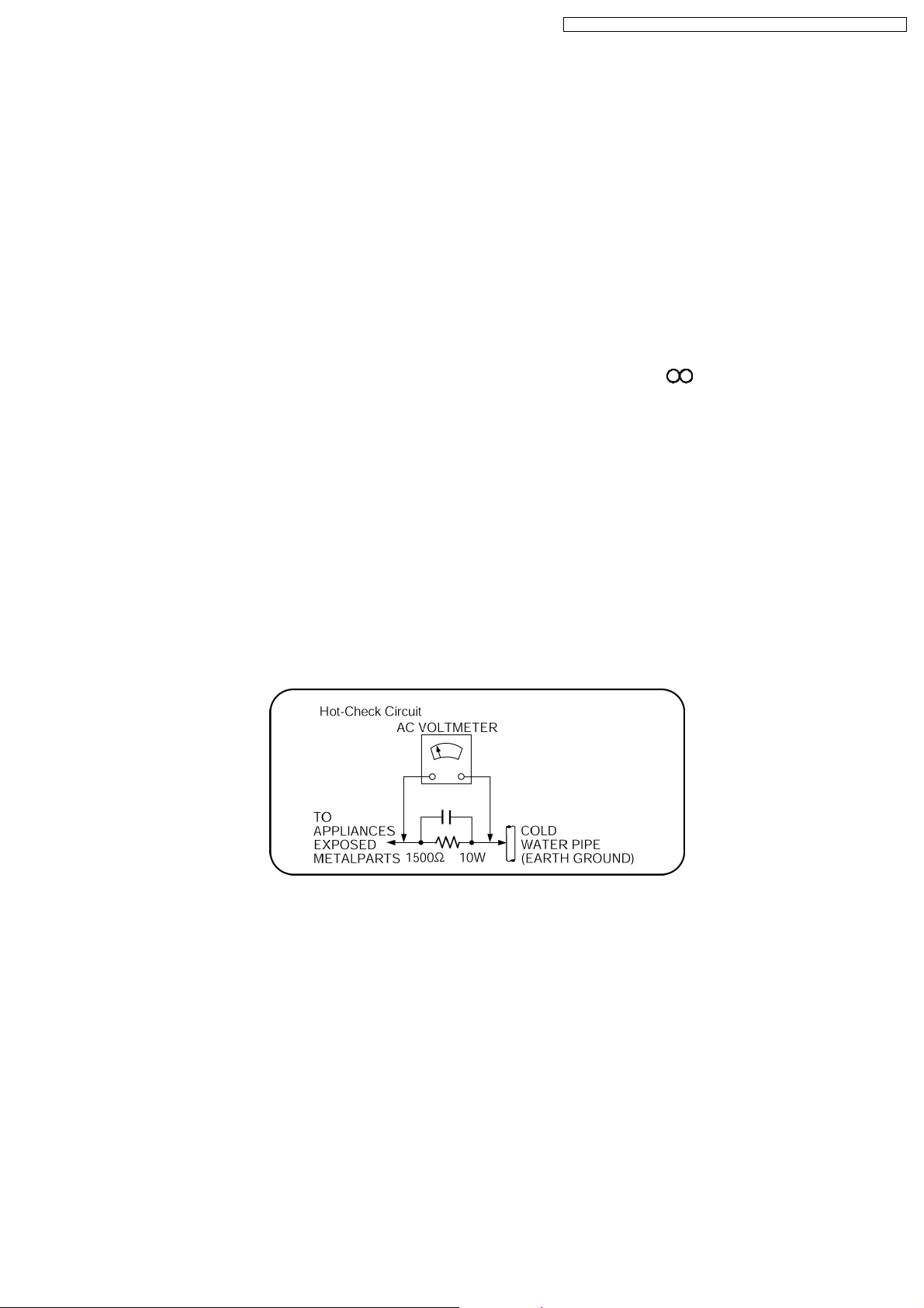
1.1.2. LEAKAGE CURRENT HOT CHECK
1. Plug the AC cord directly into the AC outlet. Do not use an isolation transformer for this check.
2. Connect a 1.5kΩ, 10 watts resistor, in parallel with a 0.15µF capacitors, between each exposed metallic part on the set and a
good earth ground such as a water pipe, as shown in Figure 1.
3. Use an AC voltmeter, with 1000 ohms/volt or more sensitivity, to measure the potential across the resistor.
4. Check each exposed metallic part, and measure the voltage at each point.
5. Reverse the AC plug in the AC outlet and repeat each of the above measurements.
6. The potential at any point should not exceed 0.75 volts RMS. A leakage current tester (Simpson Model 229 or equivalent) may
be used to make the hot checks, leakage current must not exceed 1/2 milliamp. In case a measurement is outside of the limits
specified, there is a possibility of a shock hazard, and the equipment should be repaired and rechecked before it is returned to
the customer.
Figure 1
1.2. Before Repair and Adjustment (Using SMPS Module P.C.B.)
This unit uses Switching Mode Power Supply (SMPS) Module P.C.B. to provide the neccessary voltages for the unit.
Caution:
DO NOT SHORT-CIRCUIT DIRECTLY (with a screwdriver blade, for instance), as this may destroy solid state devices.
After repairs are completed, restore power gradually using a variac, to avoid overcurrent.
Current consumption at AC 110-240 V, 50/60 Hz in NO SIGNAL mode volume minimal should be ~ 650 mA.
Note:
It is advisable to replace the SMPS Module P.C.B. as a unit.
1.3. Protection Circuitry
The protection circuitry may have operated if either of the following conditions are noticed:
· No sound is heard when the power is turned on.
· Sound stops during a performance.
5

SA-PT150GC / SA-PT150G CP / SA-PT150GCS / SA-PT150G CT / SA-PT150GS
The function of this circuitry is to prevent circuitry damage if, for example, the positive and negative speaker connection wires are
“shorted”, or if speaker systems with an impedance less than the indicated rated impedance of the amplifier are used.
If this occurs, follow the procedure outline s below:
1. Turn off the power.
2. Determine the cause of the problem and correct it.
3. Turn on the power once again after one minute.
Note:
When the protection circuitry functions, the unit will not operate unless the power is first turned off and then on again.
1.4. Safety Parts Information
Safety Parts List:
There are special components used in this equipment which are important for safety.
These parts are marked by
should be replaced with manufacturer’s specified parts to prevent shock, fire or other hazards. Do not modify the original design
without permission of manufacturer.
Reference No. Part No. Part Name & Description Remarks
340 RAE2023Z-S TRAVERSE UNIT [M]
A2 K2CQ2CA00002 AC CORD [M] GCT
A2 K2CQ2CA00007 AC CORD [M] GC/GCP/GCS
A2 K2CT3CA00004 AC CORD [M] GS
in the Schematic Diagrams & Replacement Parts List. It is essential that these critical parts
Table 1
· SMPS Module P.C.B.:
Reference No. Part No. Part Name & Description Remarks
Table 2
40 N0AZ6GE00006 SMPS MODULE [M] (RTL)
F1 K5D502BNA005 FUSE [M]
6
1.5. Caution for AC Cord
SA-PT150GC / SA-PT150G CP / SA-PT150GCS / SA-PT150G CT / SA-PT150GS
(For Saudi Arabia and Kuwait)
("GS" area code model only)
For your safety, please read the following text carefully.
This appliance is supplied with a moulded three pin
mains plug for your safety and convenience.
A 5-ampere fuse is fitted in this plug.
Should the fuse need to be replaced please ensure that
the replacement fuse has a rating of 5-ampere and that it
is approved by ASTA or BSI to BS1362.
Check for the ASTA mark or the BSI mark on the
body of the fuse.
If the plug contains a removable fuse cover you must
ensure that it is refitted when the fuse is replaced.
If you lose the fuse cover the plug must not be used until
a replacement cover is obtained.
A replacement fuse cover can be purchased from your
local dealer.
CAUTION!
IF THE FITTED MOULDED PLUG IS UNSUITABLE
FOR THE SOCKET OUTLET IN YOUR HOME THEN
THE FUSE SHOULD BE REMOVED AND THE PLUG
CUT OFF AND DISPOSED OF SAFELY.
THERE IS A DANGER OF SEVERE ELECTRICAL
SHOCK IF THE CUT OFF PLUG IS INSERTED INTO
ANY 13-AMPERE SOCKET.
If a new plug is to be fitted please observe the wiring
code as stated below.
If in any doubt please consult a qualified electrician.
IMPORTANT
The wires in this mains lead are coloured in accordance
with the following code:
Blue: Neutral, Brown: Live.
As these colours may not correspond with the coloured
markings identifying the terminals in your plug, proceed
as follows:
The wire which is coloured Blue must be connected to
the terminal which is marked with the letter N or coloured
Black or Blue.
The wire which is coloured Brown must be connected to
the terminal which is marked with the letter L or coloured
Brown or Red.
A A
WARNING: DO NOT CONNECT EITHER WIRE TO THE
EARTH TERMINAL WHICH IS MARKED WITH THE LETTER
E, BY THE EARTH SYMBOL OR COLOURED GREEN OR
GREEN/YELLOW.
THIS PLUG IS NOT WATERPROOF KEEP DRY.
Before use
Remove the connector cover.
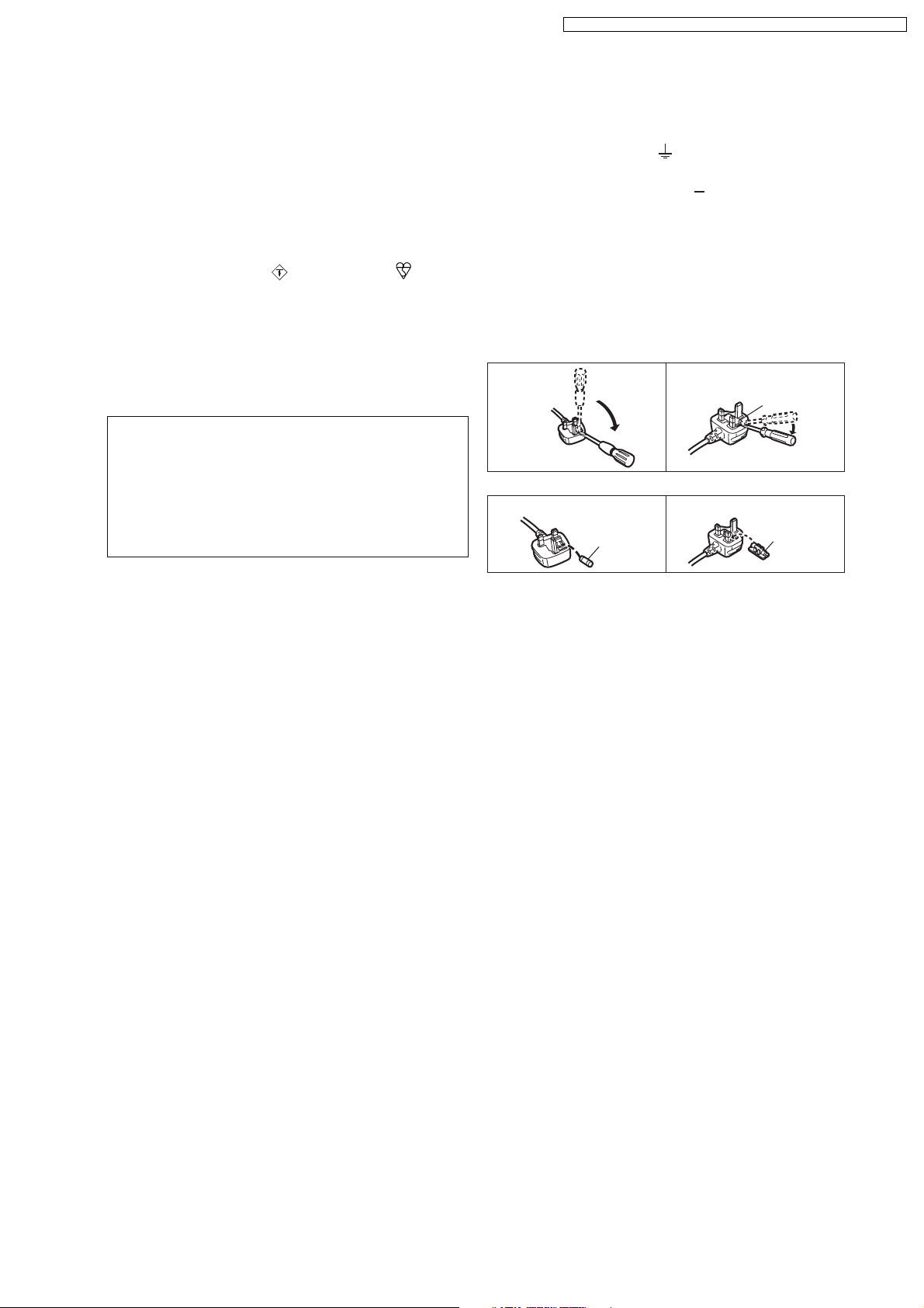
How to replace the fuse
The location of the fuse differ according to the type of AC
mains plug (figures A and B). Confirm the AC mains plug
fitted and follow the instructions below.
Illustrations may differ from actual AC mains plug.
1. Open the fuse cover with a screwdriver.
Figure A Figure B
Fuse cover
2. Replace the fuse and close or attach the fuse cover.
Figure A Figure B
Fuse
(5 ampere)
Fuse
(5 ampere)
7

SA-PT150GC / SA-PT150G CP / SA-PT150GCS / SA-PT150G CT / SA-PT150GS
2 Prevention of Electro Static Discharge (ESD) to
Electrostatically Sensitive (ES) Devices
Some semiconducto r (solid state) devices can be damaged easily by static electricity. Such components commonly are called
Electrostatically Sensitive (ES) Devices. Examples of typical ES devices are integrated circuits and some field-effect transistors and
semiconductor "chip" components. The following techniques should be used to help reduce the incidence of component damage
caused by electro static discharge (ESD).
1. Immediately before handlin g any semiconductor component or semiconductor-equipped assembly, drain off any ESD on your
body by touching a known earth ground. Alternatively, obtain and wear a commercially available discharging ESD wrist strap,
which should be removed for potential shock reasons prior to applying power to the unit under test.
2. After removing an electrical assembly equipped with ES devices, place the assembly on a conductive surface such as
aluminum foil, to prevent electrostatic charge buildup or exposure of the assembly.
3. Use only a grounded-tip soldering iron to solder or unsolder ES devices.
4. Use only an anti-static solder removal device. Some solder removal devices not classified as "anti-static (ESD protected)" can
generate electrical charge sufficient to damage ES devices.
5. Do not use freon-propelled chemicals. These can generate electrical charges sufficient to damage ES devices.
6. Do not remove a replacement ES device from its protective package until immediately before you are ready to install it. (Most
replacement ES devices are packaged with leads electrically shorted together by conductive foam, aluminum foil or comparable
conductive material).
7. Immediately before removing the protective material from the leads of a replacement ES device, touch the protective material
to the chassis or circuit assembly into which the device will be installe d.
Caution:
Be sure no power is applied to the chassis or circuit, and observe all other safety precautions.
8. Minimize bodily motions when handling unpackaged replacement ES devices. (Otherwise harmless motion such as the
brushing together of your clothes fabric or the lifting of your foot from a carpeted floor can generate static electricity (ESD)
sufficient to damage an ES device).
8
SA-PT150GC / SA-PT150G CP / SA-PT150GCS / SA-PT150G CT / SA-PT150GS
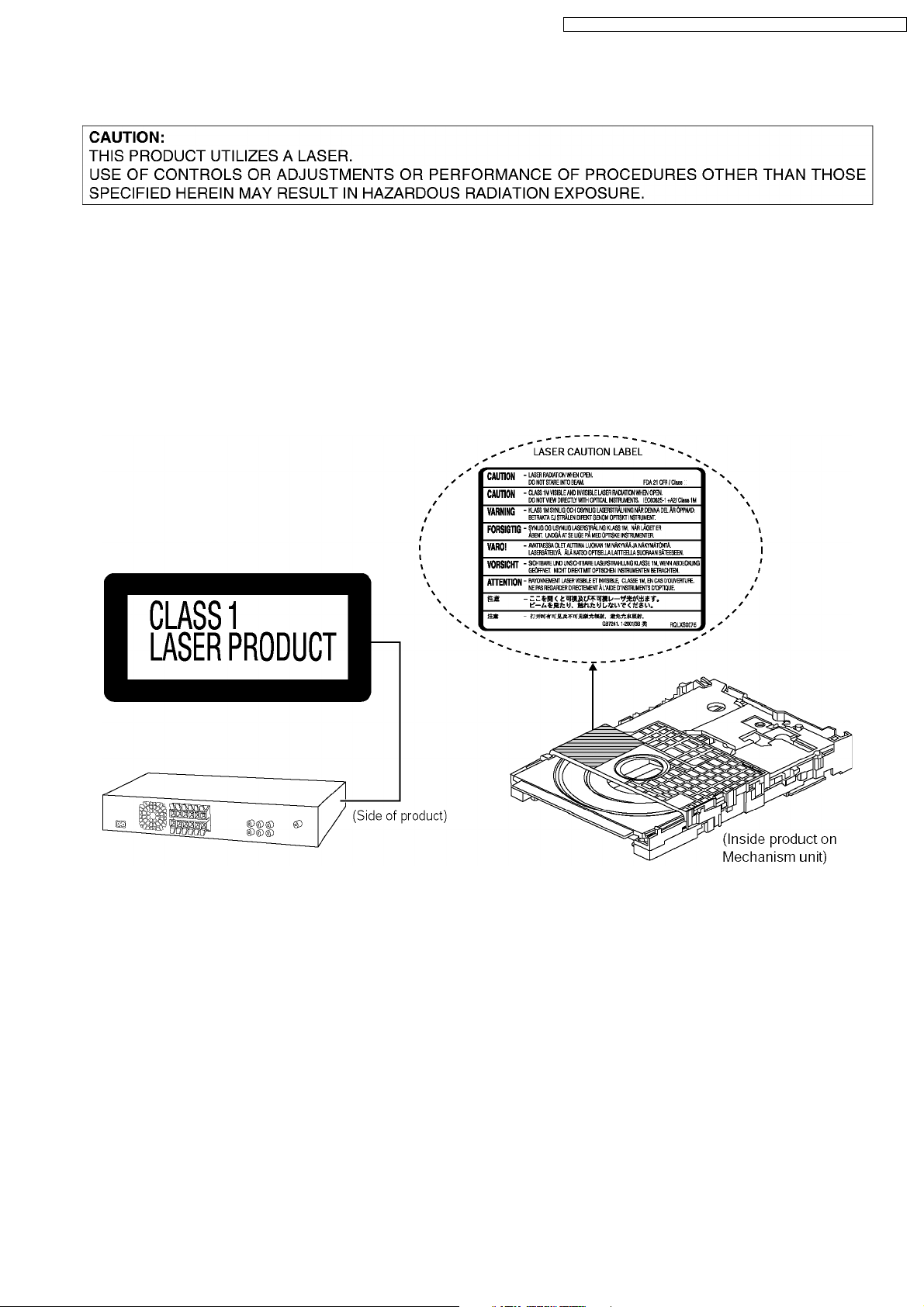
3 Precaution of Laser Diode
CAUTION :
This product utilizes a laser diode with the unit turned on, invisible laser radiation is emitted from the pickup lens.
Wavelength : 662nm/785nm
Maximum output radiation power from pickup : 100µW/VDE
Laser radiation from pickup unit is safety level, but be sure the followings:
1. Do not disassemble the pickup unit, since radiation from exposed laser diode is dangerous.
2. Do not adjust the variable resistor on the pickup unit. It was already adjusted.
3. Do not look at the focus lens using optical instruments.
4. Recommend not to look at pickup lens for a long time.
9

SA-PT150GC / SA-PT150G CP / SA-PT150GCS / SA-PT150G CT / SA-PT150GS
4 About Lead Free Solder (PbF)
4.1. Service caution based on legal restrictions
4.1.1. General description about Lead Free Solder (PbF)
The lead free solder has been used in the mounting process of all electrical components on the printed circuit boards used for this
equipment in considering the globally environmental conservation.
The normal solder is the alloy of tin (Sn) and lead (Pb). On the other hand, the lead free solder is the alloy mainly consists of tin
(Sn), silver (Ag) and Copper (Cu), and the melting point of the lead free solder is higher approx.30 degrees C (86°F) more than that
of the normal solder.
Definition of PCB Lead Free Solder being used
The letter of “PbF” is printed either foil side or components side on the PCB using the lead free solder.
(See right figure)
Service caution for repair work using Lead Free Solder (PbF)
· The lead free solder has to be used when repairing the equipment for which the lead free solder is used.
(Definition: The letter of “PbF” is printed on the PCB using the lead free solder.)
· To put lead free solder, it should be well molten and mixed with the original lead free solder.
· Remove the remaining lead free solder on the PCB cleanly for soldering of the new IC.
· Since the melting point of the lead free solder is higher than that of the normal lead solder, it takes the longer time to melt
the lead free solder.
· Use the soldering iron (more than 70W) equipped with the temperature control after setting the temperature at 350±30
degrees C (662±86°F).
Recommended Lead Free Solder (Service Parts Route.)
· The following 3 types of lead free solder are available through the service parts route.
RFKZ03D01K-----------(0.3mm 100g Reel)
RFKZ06D01K-----------(0.6mm 100g Reel)
RFKZ10D01K-----------(1.0mm 100g Reel)
Note
* Ingredient: tin (Sn), 96.5%, silver (Ag) 3.0%, Copper (Cu) 0.5%, Cobalt (Co) / Germanium (Ge) 0.1 to 0.3%
10
SA-PT150GC / SA-PT150G CP / SA-PT150GCS / SA-PT150G CT / SA-PT150GS
5 Handling Precautions for Traverse Unit
The laser diode in the optical pickup unit may break down due to static electricity of clothes or human body. Special care must be
taken avoid caution to electrostatic breakdown when servicing and handling the laser diode.
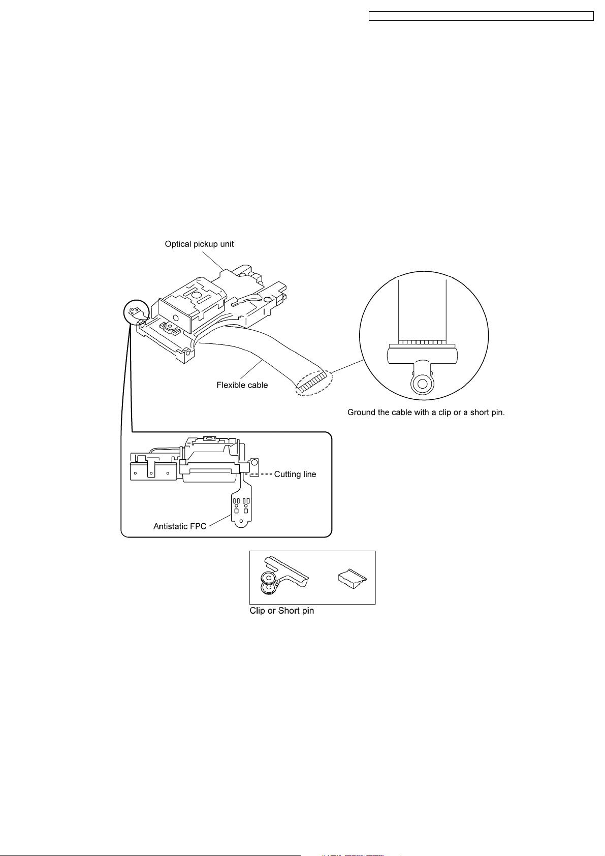
5.1. Cautions to Be Taken in Handling the Optical Pickup Unit
The laser diode in the optical pickup unit may be damaged due to electrostatic discharge generating from clothes or human body.
Special care must be taken avoid caution to electrostatic discharge damage when servicing the laser diode.
1. Do not give a considerable shock to the optical pickup unit as it has an extremely high-precise structure.
2. To prevent the laser diode from the electrostatic discharge damage, the flexible cable of the optical pickup unit removed should
be short-circuited with a short pin or a clip.
3. The flexible cable may be cut off if an excessive force is applied to it. Use caution when handling the flexible cable.
4. The antistatic FPC is connected to the new optical pickup unit. After replacing the optical pickup unit and connecting the flexible
cable, cut off the antistatic FPC.
5.2. Grounding for electrostatic breakdown prevention
Some devices such as the DVD player use the optical pickup (laser diode) and the optical pickup will be damaged by static
electricity in the working environment. Proceed servicing works under the working environment where grounding works is
completed.
5.2.1. Worktable grounding
1. Put a conductive material (sheet) or iron sheet on the area where the optical pickup is placed, and ground the sheet.
5.2.2. Human body grounding
1. Use the anti-static wrist strap to discharge the static electricity form your body.
11

SA-PT150GC / SA-PT150G CP / SA-PT150GCS / SA-PT150G CT / SA-PT150GS
12
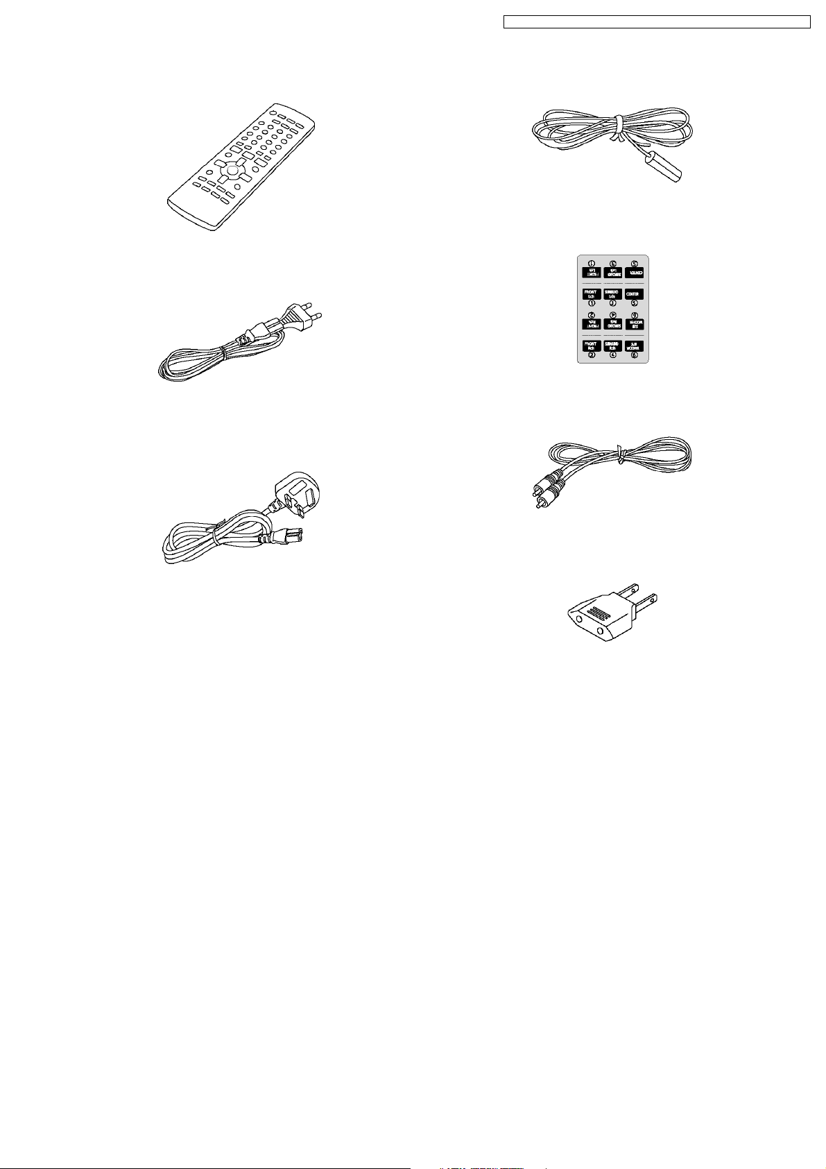
6 Accessories
Remote control
AC cord
(For GC/GCP/GCS/GCT areas)
SA-PT150GC / SA-PT150G CP / SA-PT150GCS / SA-PT150G CT / SA-PT150GS
Antenna wire
Speaker label
AC cord
(For GS area only)
Video cable
AC plug adaptor
13
SA-PT150GC / SA-PT150G CP / SA-PT150GCS / SA-PT150G CT / SA-PT150GS
7 Operation Procedures
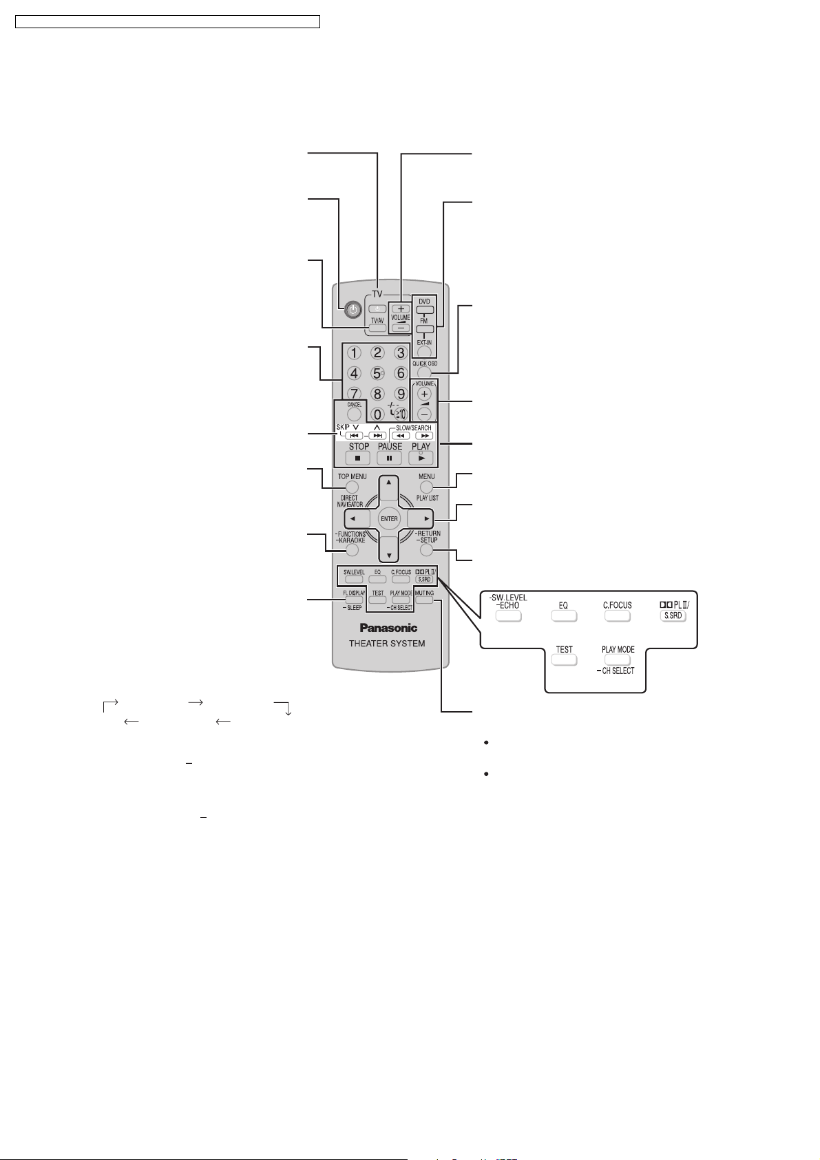
7.1. Remote Control Key Buttons Operations
Telev isi o n op era t ion s
Switch the main unit on or off
Change the television’s video
input mode
Select disc’s title numbers and etc.,
Enter numbers
Select preset radio stations
or program list
Show on-screen menu
Karaoke
Show the display on the
main unit
Adjust the television volume
Select the source
DVD: DVD / CD
FM
EXT-IN:
Show the current disc’s playback
condition
Adjust the volume of the main unit
Basic operations for play
Show a disc top menu
Show a disc menu or play list
Select or confirm menu items on the
television screen, Frame-by-frame
Return to previous screen,
Show the Setup menu
AUX, USB
Set the sleep timer
This function enables you to turn
off the unit automatically after the
set time.
SLEEP 30 SLEEP 60
OFF SLEEP 120 SLEEP 90
To cancel the timer
Press and hold [ SLEEP] to select
"OFF".
To confirm the remaining time
Press and hold [ SLEEP] again.
To mute the sound
To cancel
Press [MUTING] again or adjust
the volume.
Muting is cancelled when you
switch the unit to standby.
14
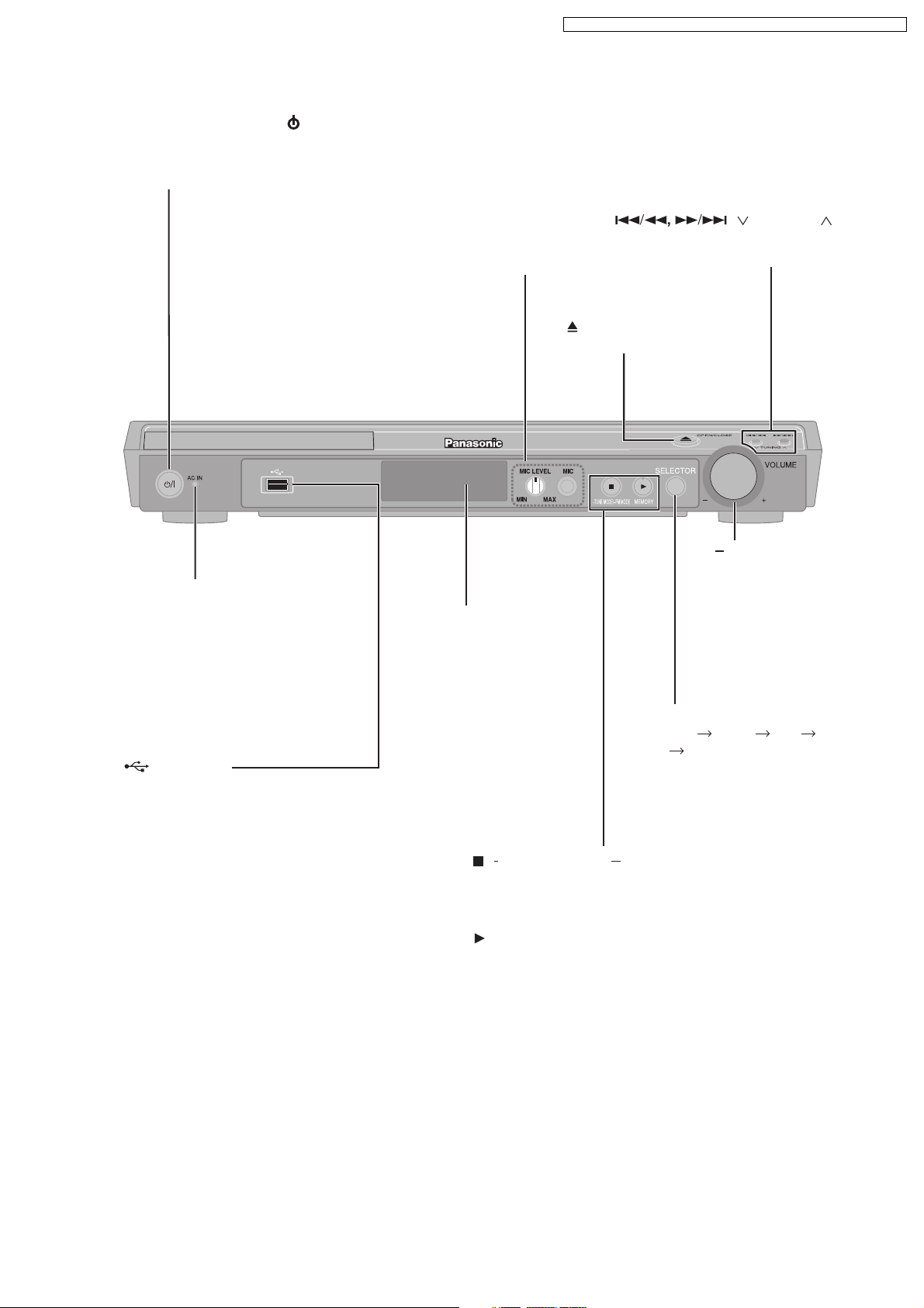
7.2. Main Unit Key Buttons Operations
Standby/on switch [ /I]
Press to switch the unit from on to standby
mode or vice versa. In standby mode, the unit
is still consuming a small amount of power.
SA-PT150GC / SA-PT150G CP / SA-PT150GCS / SA-PT150G CT / SA-PT150GS
AC supply indicator [AC IN]
This indicator lights when the unit
is connected to the AC mains
supply.
MIC jack
Connect a microphone
MIC LEVEL
Adjust the microphone volume
OPEN/CLOSE
Open or close the disc tray
Display
/ TUNING
Skipping or slow-search play,
Select the radio stations
+, VOLUME
Turn the volume
up or down
USB port
Connect a USB device
SELECTOR
DVD/CD USB FM
AUX Returns to DVD/CD
/ TUNE MODE / FM MODE
Stop playback,
Select the tuning mode,
Adjust the FM reception condition
/MEMORY
Disc playback,
Memorize the receiving radio stations
15
SA-PT150GC / SA-PT150G CP / SA-PT150GCS / SA-PT150G CT / SA-PT150GS
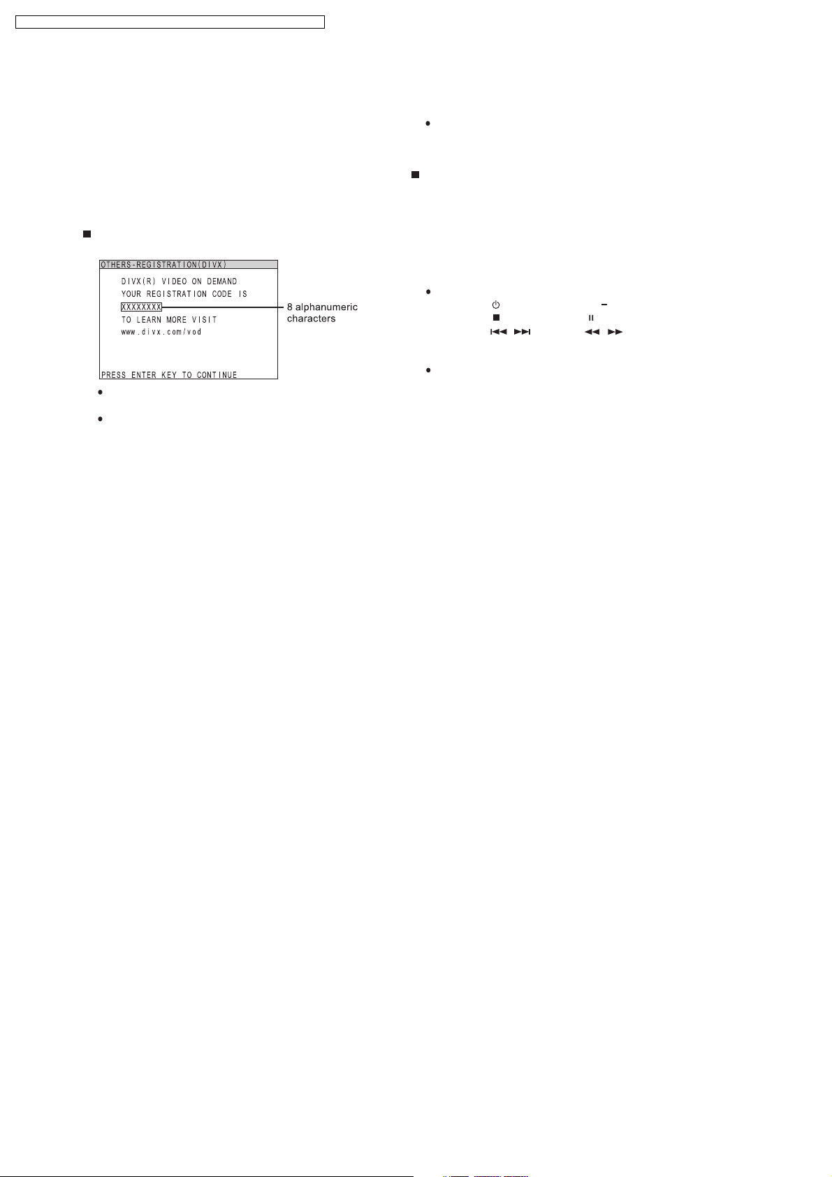
7.3. About DivX VOD Content
DivX Video-on-Demand (VOD) content is encrypted for
copyright protection. In order to play DivX VOD content on
this unit, you first n eed to register the unit.
Follow the online instructions for purchasing DivX VOD
content to enter the unit’s registration code and register the
unit. For more information about DivX VOD, visit
www.divx.com/vod.
Display the unit’ s registration code
(OI page 23, "REGISTRATION (DIVX)" in "OTHERS" tab)
We recommend that you make a note of this code for
future reference.
After playing DivX VOD content for the first time,
another registration code is then displayed in
"REGISTRATION (DIVX)". Do not use this registration
code to purchase DivX VOD content. If you use this
code to purchase DivX VOD content, and then play
the content on this unit, you will no longer be able to
play any content that you purchased using the previous
code.
If you purchase DivX VOD content using a registration
code different from this unit’s code, you will not be able
to play this content. ("Authorization Error" is displayed.)
Regarding DivX content that can only be played
a set number of times
Some DivX VOD content can only be played a set number
of times. When you play this content, the remaining
number of plays is displayed. You cannot play this content
when the number of remaining plays is zero. ("RENTAL
EXPIRED" is displayed.)
When playing this content
The number of remaining plays is reduced by one if
you press [ ] or press and hold [ SETUP].
you press [ , STOP]. (Press [ , PAUSE] to pause play.)
you press [, ] (skip) or [, ] (slow/search)
and arrive at another content or the start of the content
being played.
Resume (OI page 15, Stop) function does not work.
etc.
16
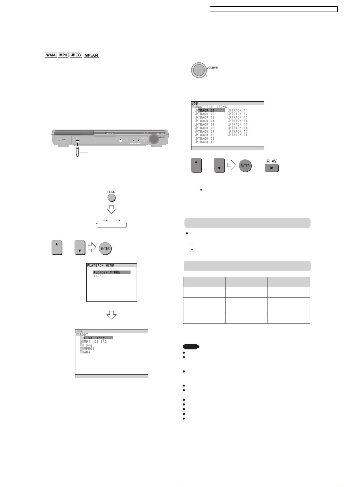
7.4. USB Connection and Operation
Optional USB connecti on and operation
Optional USB connection and operation
SA-PT150GC / SA-PT150G CP / SA-PT150GCS / SA-PT150G CT / SA-PT150GS
The USB connectivity enables you to connect and play
tracks or files f rom USB mass storage class devices.
Typically, USB memory devices. (Bulk only transfer)
Preparation
Before connecting any USB mass storage device to the
unit, ensure that the data stored therein has been backed
up.
It is not recommended to use a USB extension cable. The
USB device is not recognised by this unit.
1 Connect the USB mass storage device (not included).
USB enabled device
(not included)
It is not recommended to use a USB
extension cable. The device connected
via the cable will not be recognised by
this unit.
2 To select "USB" as the source, press several times.
USB AV AUX
3 Adjust the volume of the main unit.
4 Begin playback by selecting the track from the USB
mass storage device.
Example:
OR
To return to the previous screen
Press [ RETURN ].
For other operating functions, they are similar as those
described on "DISC OPERATION". (OI page 14 to 25)
Compatible Devices
OR
Select the desired item for playback.
OR
Example:
Devices which are defined as USB mass storage
class:
USB devices that support bulk only transfer.
USB devices that support USB 2.0 full speed.
Supported Formats
File name File extension
WMA
1
*
.jpg .jpeg
.mp3
.wma
2
*
Still pictures JPG
Music MP3
Video MPEG4 .asf
1
It may not be p ossible to play all the files due to the condition on
*
how they were created.
2
For Panasonic D-Snap/DIGA.
*
Note
CBI (Control/Bulk/Interrupt) is not supported.
Digital Cameras that use PTP protoc ol or which require
additional program installation when connected to a PC are not
supported.
A device using NTFS file system is not supported.
[Only FAT 16/32 (File Allocation Table 16/32) file system is
supported].
Depending on the sector size, some files m ay not work.
It will not operate with Janus enabled MTP (Media Transfer
Protocol) devices.
Maximum folder: 256 folders
Maximum file: : 4000 files
Maximum file name: 12 characters
Maximum folder name: 12 characters
Only one memory c ard will be selected when connecting a
multiport USB card reader. Typically the first memory card
inserted.
17
SA-PT150GC / SA-PT150G CP / SA-PT150GCS / SA-PT150G CT / SA-PT150GS
7.5. Audio and Video Connections
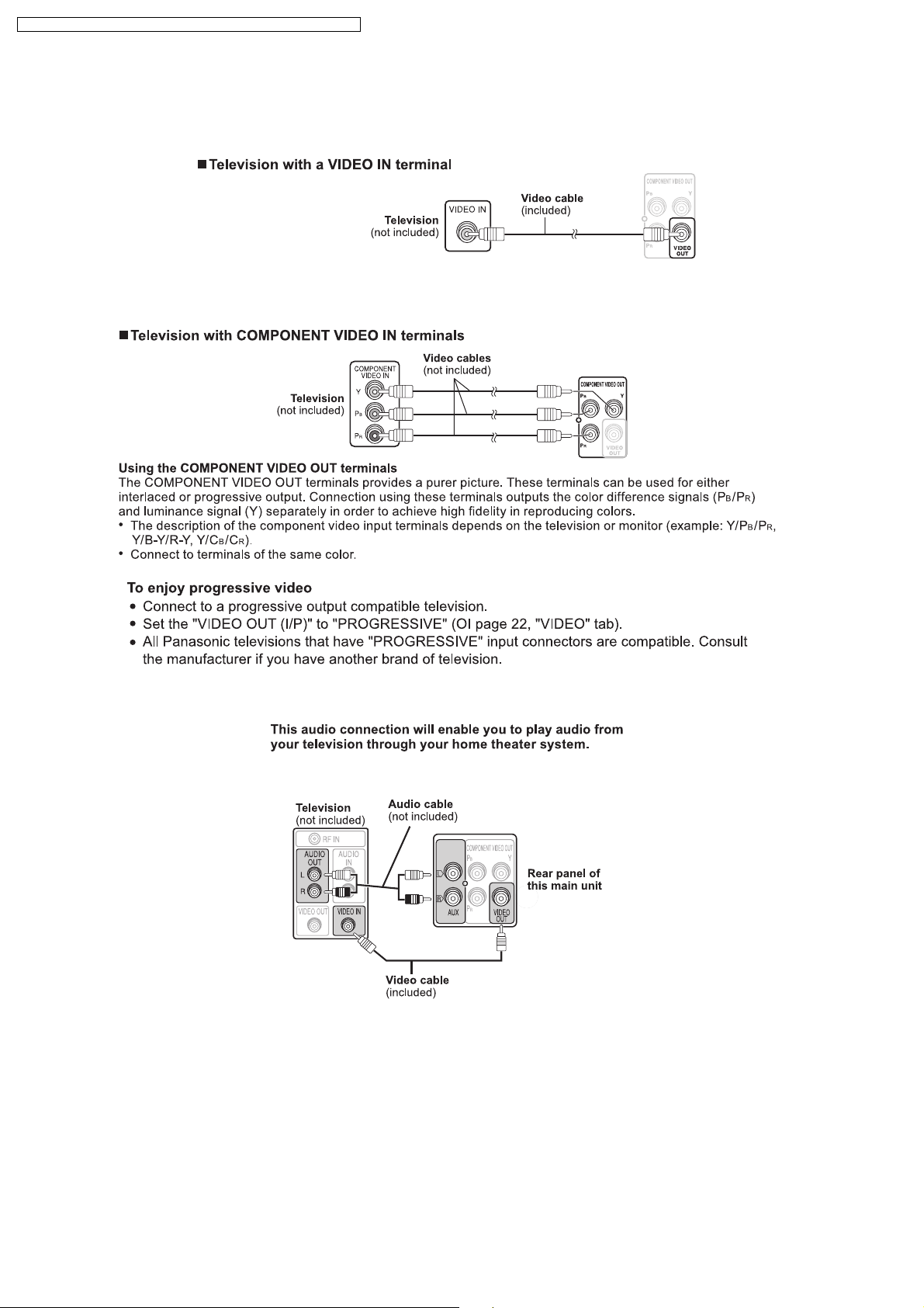
7.5.1. Television with Video In Terminal
7.5.2. Television with Component Video In Terminals
7.5.3. Audio Connection for Video Cassette Recorder or Television
18
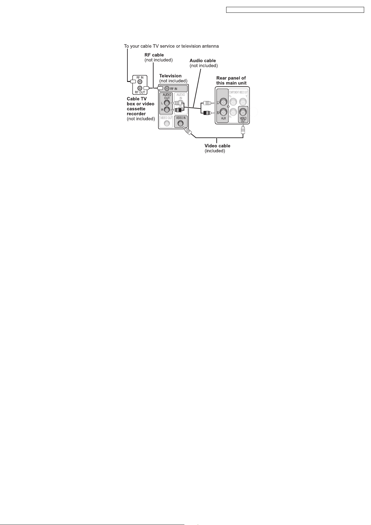
7.5.4. Connection for Set Top Box
SA-PT150GC / SA-PT150G CP / SA-PT150GCS / SA-PT150G CT / SA-PT150GS
19
Discs that can be played
SA-PT150GC / SA-PT150G CP / SA-PT150GCS / SA-PT150G CT / SA-PT150GS
7.6. Disc Information
7.6.1. Disc Playability (Media)
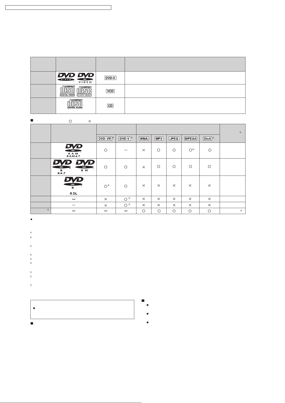
Discs that can be played
Disc Logo
Indicated in
these
instructions by
Remarks
DVD-Video
Video CD
CD
Recorded discs
Disc Logo
DVD- RAM
DVD- R/ RW
DVD- R DL
+R/+RW Necessary
+R DL Necessary
CD-R/RW Necessary
1
( : Playable, : Not playable)
Recorded on a DVD
video recorder, etc.
3
High quality movie and music disc s.
Music discs with video.
Including SVCD (Conforming to IEC62107).
Music discs.
Recorded on a personal computer, etc.
2
()
()
4
8
5
5
9
Finalizing
Not
necessary
Necessary
Necessary
6
7
It may not be possible to play all the above-mentioned discs in some cases due to the type of disc, the condition of the
recording, the recording method, or how the files were created [ Item 7.6.2 File Extension Type Support (WMA/MP3/JPEG/
1
This unit can play CD-R/RW recorded with CD-DA or Video CD format.
2
Discs recorded on DVD video recorders or DVD video cameras, etc. using Version 1.1 of the Video Recording Format (a uni ed video
recording standard).
3
Discs rec orded on DVD video recorders or DVD video cameras using Version 1.2 o f the Video Recording Format (a uni efi d video
recording standard).
4
Discs recorded on DVD video recorders or DVD video cameras using DVD-Video Format.
5
Recorded using a format dif ferent from DVD-Video Format, therefore, some functions cannot be used.
6
A process that allows play on compatible equipment. To play a disc that is displa yed as "Necessary" on this unit, the disc must rfi st be
nfi alized on the device it was recorded on.
7
Closing the session will also work.
8
MPEG4 data recorded with the Panasonic SD multi cameras or DVD video recorders [conforming to SD VIDEO spec ifications (ASF
standard)/ MPEG4 (Simple Profi le) video system/ G.726 audio system] .
9
Functions added with DivX ultra are not supported.
Note about using a DualDisc
The digital audio content side of a DualDisc does not meet the
technical specifi cations of the Compac t Disc Digital Audio
(CD-DA) format so playback may not be possible.
Discs that cannot be played
DVD-RW version 1.0, DVD-Audio, DVD-ROM, CD-ROM,
CDV, CD-G, SACD, Photo CD, DVD-RAM that cannot be
MPEG4/DivX]
fi
Video systems
This unit can play PAL and NTSC, but your television
must match the system used on the disc.
PAL discs cannot be correctly viewed on an NTSC
television.
This unit can convert NTSC signals to PAL 60 for
viewing on a PAL television. (OI page 22, "NTSC DISC
OUT" in "VIDEO" tab.)
removed from their cartridge, 2.6-GB and 5.2-GB DVD-
RAM, and "Chaoji VCD" available on the market including
CVD, DVCD and SVCD that do not conform to IEC62107.
20

7.6.2. File Extension Type Support (WMA/MP3/JPEG/MPEG4/DivX)
Ti ps for making data discs
Tips for making data discs
When there are more than eight groups, the eighth group onwards will be displayed on one vertical line in the menu
screen.
There may be differences in the display order on the menu screen and computer screen.
This unit cannot play lfi es recorded using packet write.
DVD-RAM
Discs must conform to UDF 2.0.
DVD-R/RW
Discs must conform to UDF bridge (UDF 1.02/ISO9660).
This unit does not support multi-session. Only the default session is played.
CD-R/RW
Discs must conform to ISO9660 level 1 or 2 (except for extended formats).
This unit supports multi-session but if there are many sessions it takes more time for play to start. Keep the number of
sessions to a minimum to avoid this.
Naming folders and files
Files are treated as contents and folders are treated as groups on this unit.
At the time of recording, prefi fix folder and le names. This should be with numbers that have
an equal number of digits, and should be done in the order you want to play them (this may
not work at times). Files must have the extension ( see below).
(Extension: ".WMA" or ".wma")
Compatible compression rate: bet ween 48 kbps and 320 kbps.
You cannot play WMA files that are copy-protected.
This unit does not support Multiple Bit Rate (MBR).
(Extension: ".MP3" or ".mp3")
Compatible compression rate: bet ween 32 kbps and 320 kbps.
This unit does not support ID3 tags.
Compatible sampling rates:
DVD-RAM, DVD-R/RW: 11.02, 12, 22.05, 24, 44.1 and 48 kHz
CD-R/RW: 8, 11.02, 12, 16, 22.05, 24, 32, 44.1 and 48 kHz
(Extension: ".JPG", ".jpg", ".JPEG" or ".jpeg")
JPEG lfi es taken on a digital camera that conform to DCF Standard (Design rule for Camera F ile system) Version 1.0 are
displayed. Files that have been altered, edited or saved with computer picture edi ting sof tware may not be displayed.
This unit cannot display moving pictures, MOTION JPEG and other such formats, and still pictures other than JPEG
(Example: TIFF), or play pictures with attached audio.
(Extension: ".ASF" or ".asf")
You can play MPEG4 data [conforming to SD VIDEO speci cfi ations (ASF standard)/MPEG4 (Simple Pro le) video
system/G.726 audio system] recorded with Panasonic SD multi cameras or DVD video rec orders with this unit.
The recording date may differ from that of the actual date.
(E xtens ion: ".DIVX", ".divx", ".AVI" or ".av i")
You can play all versions of DivX video (including DivX
system] with standard playback of DivX media lfi es. Functions added with DivX Ultra are not supported.
GMC (Global Motion Compensation) is not supported.
DivX les greater than 2 GB or have no index may not be played properly on this unit.
fi
This unit supports all resolutions up to maximum of 720 x 480 (NTSC)/720 x 576 (PAL).
You can select up to eight types of audio and subtitles on this unit.
SA-PT150GC / SA-PT150G CP / SA-PT150GCS / SA-PT150G CT / SA-PT150GS
fi
6) [DivX video system/MP3, Dolby Digital or MPEG audio
21
SA-PT150GC / SA-PT150G CP / SA-PT150GCS / SA-PT150G CT / SA-PT150GS
8 Self-Diagnosis and Special Mode Setting
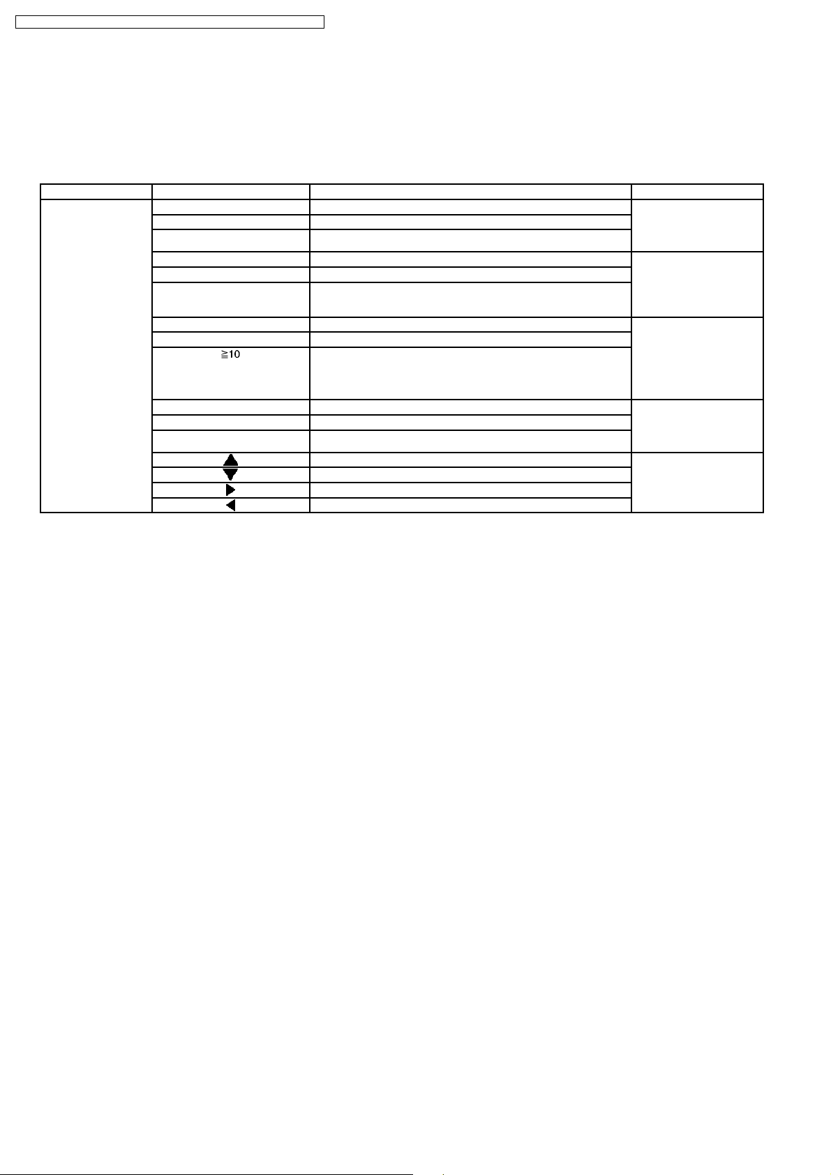
8.1. Service Mode Summary Table
The service modes can be activated by pressing various button combination on the main unit and remote control unit.
Below is the summary for the various modes for checking:
Player buttons Remote control unit buttons Application Note
[STOP] [0] Error code check. (Refer to the section
[5] Jitter checking.
[PAUSE] Initial setting of laser drive current.
[FUNCTIONS] DVD laser drive current check. (Refer to the section
[1] ADSC internal RAM data check.
[3] CD laser drive current check.
“8.2.1. Service Mode
Table 1” for more
information.)
“8.2.2. Service Mode
Table 2” for more
information.)
[6] Region display and mode. (Refer to the section
[7] Micro-processor firmware version check.
[ ] Initialization of the player (factory setting is restored).
Used after replacement of Micro-processor (DV5 LSI) IC, FLASH
ROM IC (IC8651), EEPROM IC (IC8611) and DVD Module
P.C.B.
[8] DVD Module P.C.B. firmware version check. (Refer to the section
[EQ] CPPM/CRM keys check.
[ENTER] DVD Module P.C.B. reset.
[ ] Timer 1 check. (Refer to the section
[ ] Timer 1 reset.
[ ] Timer 2 check.
[ ] Timer 2 reset.
“8.2.3. Service Mode
Table 3“ for more
information.)
“8.2.4. Service Mode
Table 4“ for more
information.)
“8.2.5. Service Mode
Table 5“ for more
information.)
Note:
An error code will be canceled if a power supply is turned OFF.
*1: CPPM is the copy guard function beforehand written in the disk for protection of copyrights.
*2: CEC is the consum er electronic control used for high-level user control of HDMI-connected devices.
*3: HDCP is the specification developed to control digital audio & video contents transmission for DVI or HDMI connections.
8.2. Service Mode Table
By pressing various button combinations on the main unit and remote control unit, you can activate the various service modes for
checking.
Special Note:
· Due to the limitations of the no. characters that can be shown on the FL Display, the “FL Display” button on the remote
control unit can be used to show the two display pages. (Display 1 / Display 2).
· Refer to Section 7.1 for the section on “Remote Control Key Buttons Operations”.
22
8.2.1. Service Mode Table 1
SA-PT150GC / SA-PT150G CP / SA-PT150GCS / SA-PT150G CT / SA-PT150GS
Mode Name
Jitter check
Error code
check
Item
Description
Jitter check.
Jitter rate is measured and displayed.
Measurement is repeatedly done in
the cycle of one second. Read error
counter starts from zero upon mode
setting.
When target block data failed to be
read out, the counter advances by one
increment. When the failure is caused
by minor error, it may be corrected
when retried to enable successful
reading.
In this case, the counter advances by
one. When the error persists even
after retry, the counter may jump by
two or more.
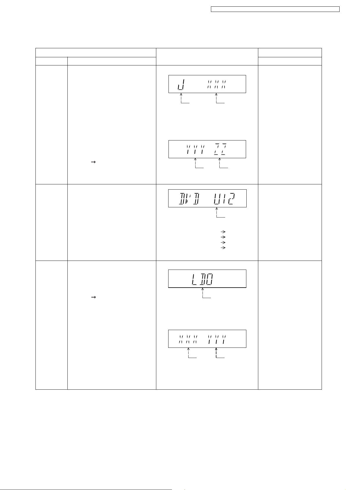
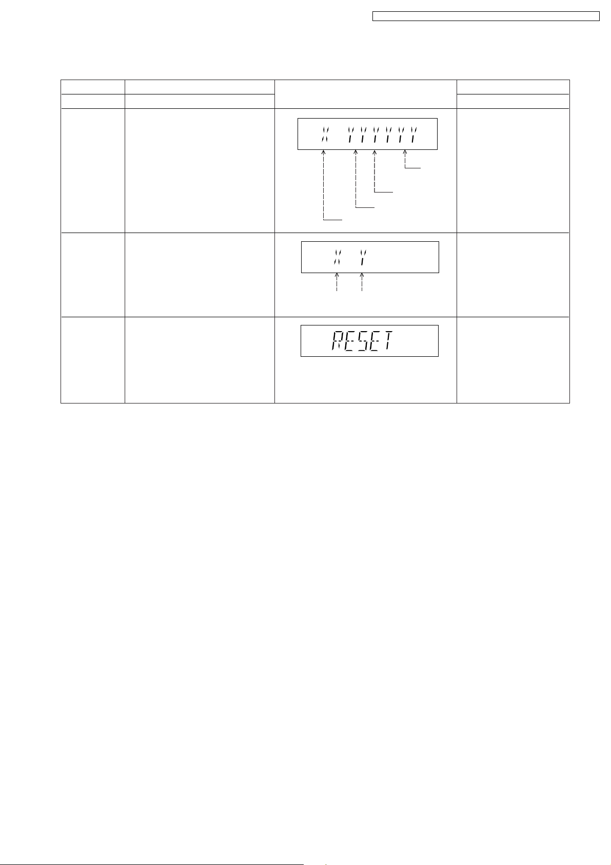
FL Display sequence:
Display 1 2.
Error code check
The latest error code stored in the
EEPROM IC is displayed.
Note: Refer to "Section 8.3 DVD Self
Diagnostic Function-Error Code" for
more detailed information on the error
codes.
FL Display
(Display 1)
Jitter check
mode
Jitter rate is shown in decimal notation to
one place of decimal.
Focus drive value is shown in hexadecimal
notation.
(Display 2)
Lead
Error
Counter
Error code (play_err) is expressed in the
following convention.
Error code = 0 x DAXX is expressed: DVDnn U12
Error code = 0 x DBXX is expressed: DVDnn H12
Error code = 0 x DXXX is expressed: DVDnn F123
Error code = 0 x 0000 is expressed: DVDnn F--* "xx" denotes the error code
Jitter rate
Focus Drive
Value
U / H / F
Key Operation
Front Key
In STOP (no disc) mode,
press [STOP] button on the
main unit, and [5] button on
the remote control unit.
Press [POWER] button to
exit.
Press [FL Display] on
remote control unit for next
page (FL Display).
In STOP (no disc) mode,
press [STOP] button on the
main unit, and [0] button on
the remote control unit. * With
pointing of cursor up and
down on display.
Cancelled automatically
5 seconds later.
To exit, press [POWER]
button on main unit or
remote control.
Initial setting
of laser drive
current
Initial setting of laser drive current.
Initial current value for the DVD laser
and CD laser is separately saved in
the EEPROM IC.
FL Display sequence:
Display 1 2.
(Display 1)
Laser current
measurement
CD
Laser
mode
DVD Laser
The value denotes the current in decimal
notation.
(Display 2)
The above example shows the initial
current is XXXmA and YYYmA for CD
laser and DVD laser respectively when
the laser is switched on.
In STOP (no disc) mode,
press [STOP] button on the
main unit, and [PAUSE]
button on the remote
control unit.
Cancelled automatically
5 seconds later.
Press [FL Display] on
remote control unit for next
page (FL Display) on values
of laser drive current.
23
SA-PT150GC / SA-PT150G CP / SA-PT150GCS / SA-PT150G CT / SA-PT150GS
8.2.2. Service Mode Table 2
DVD laser
drive current
measurement
ADSC internal
RAM data
check
Item
DescriptionMode Name
DVD laser drive current measurement.
DVD laser drive current is measured
and the result is displayed together
with the initial value stored in the
EEPROM IC.
After the measurement, DVD laser
emission is kept on. It is turned off
when POWER key is switched off.
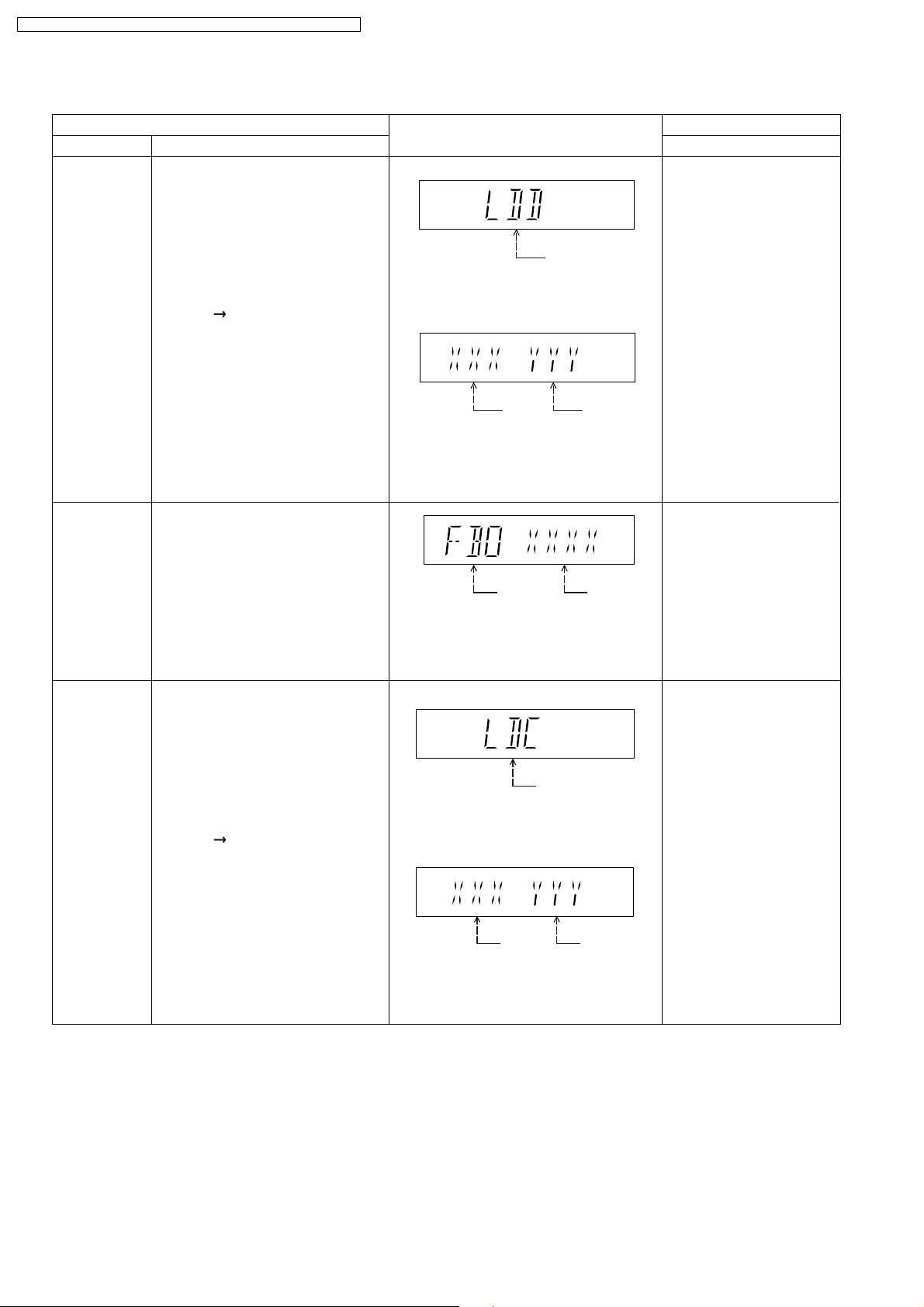
FL Display sequence:
Display 1 2.
ADSC internal RAM data check.
ADSC internal RAM data is read out
and displayed.
FL Display
(Display 1)
DVD laser current
measurement mode
The value denotes the current in decimal
notation.
(Display 2)
DVD
Laser
Initial Value
The above example shows the initial
current is XXXmA and the measured
value is YYYmA.
Address
The value is shown in hexadecimal
notation. The above example shows the
data in ADSC address FBOh is XXXXh.
DVD
Laser
Value
RAM data
for specified
address
Key Operation
Front Key
In STOP (no disc) mode,
press [STOP] button on the
main unit, and
[FUNCTIONS] button on
the remote control unit.
Cancelled automatically
5 seconds later.
Press [FL Display] on
remote control unit for next
page (FL Display) on values
of dvd drive current.
In STOP (no disc) mode,
press [STOP] button on
the main unit, and [1]
button on the remote
To exit, press [POWER]
button.
CD laser drive
current
measurement
CD laser drive current measurement.
CD laser drive current is measured
and the result is displayed together
with the initial value stored in the
EEPROM IC.
After the measurement, CD laser
emission is kept on. It is turned off
when POWER key is switched off.
FL Display sequence:
Display 1 2.
(Display 1)
CD laser current
measurement mode
The value denotes the current in decimal
notation.
(Display 2)
CD
laser initial
value
The above example shows the initial current
is 0XXmA and the measured value is 0YYmA.
CD laser
value
In STOP (no disc) mode,
press [STOP] button on
the main unit, and [3]
button on the remote
control unit.
Cancelled automatically
5 seconds later.
Press [FL Display] on
remote control unit for next
page. (FL Display)
24
8.2.3. Service Mode Table 3
SA-PT150GC / SA-PT150G CP / SA-PT150GCS / SA-PT150G CT / SA-PT150GS
Micro-processor
firmware version
display &
EEPROM
checksum
display.
Item
DescriptionMode Name
Micro-processor firmware version
display & EEPROM checksum display.
EEPROM checksum is only available
due to existence of EEPROM IC.
Note: Condition 1/2/3 shows the state
of EEPROM IC.
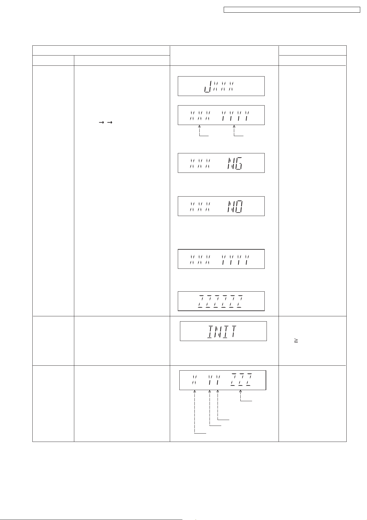
FL Display sequence:
Display 1 2 3.
FL Display
(Display 1)
(Display 2)
Opecon
Version
(Condition1)
If the version of the EEPROM does not match,
[NG] is displayed.
(Condition 2)
(a) If there is NO EEPROM header string
OR
(b) If there is no EEPROM (no data is received
by Micro-processor), [NO] is displayed.
(Condition 3)
EEPROM
Checksum
(If applicable,
refer below.)
Key Operation
Front Key
In STOP (no disc)
mode, press [STOP]
button on the main unit,
and [7] button on the
remote control unit.
Cancelled automatically
5 seconds later.
Initialization
Region display
Initialization.
User settings are cancelled and player
is initialized to factory setting.
It is necessary when after replacement
of Micro-processor (DV5 LSI) IC,
FLASH ROM IC (IC8651), EEPROM
IC (IC8611) & DVD Module P.C.B.
Region code display, TV broadcasting
system & the model no. information.
Note: Refer to Figure 2 for "Video
Design Information".
If the EEPROM version matches, checksum
[YYYY] is displayed.
(Display 3)
Model
No.
Information
N: NTSC / 6: PAL60
N: no PAL / P: PAL
Region No.: 0-8
Press [FL Display] button on
remote control unit for next
page. (FL Display)
In STOP (no disc)
mode, press [STOP]
button on the main unit,
and [ 10] button on the
remote control unit.
Cancelled automatically
5 seconds later.
In STOP (no disc)
mode, press [STOP]
button on the main unit,
and [6] button on the
remote control unit.
Cancelled automatically
5 seconds later.
25
5P6
3PN
4P6
2P6
2P6
1PN
2P6
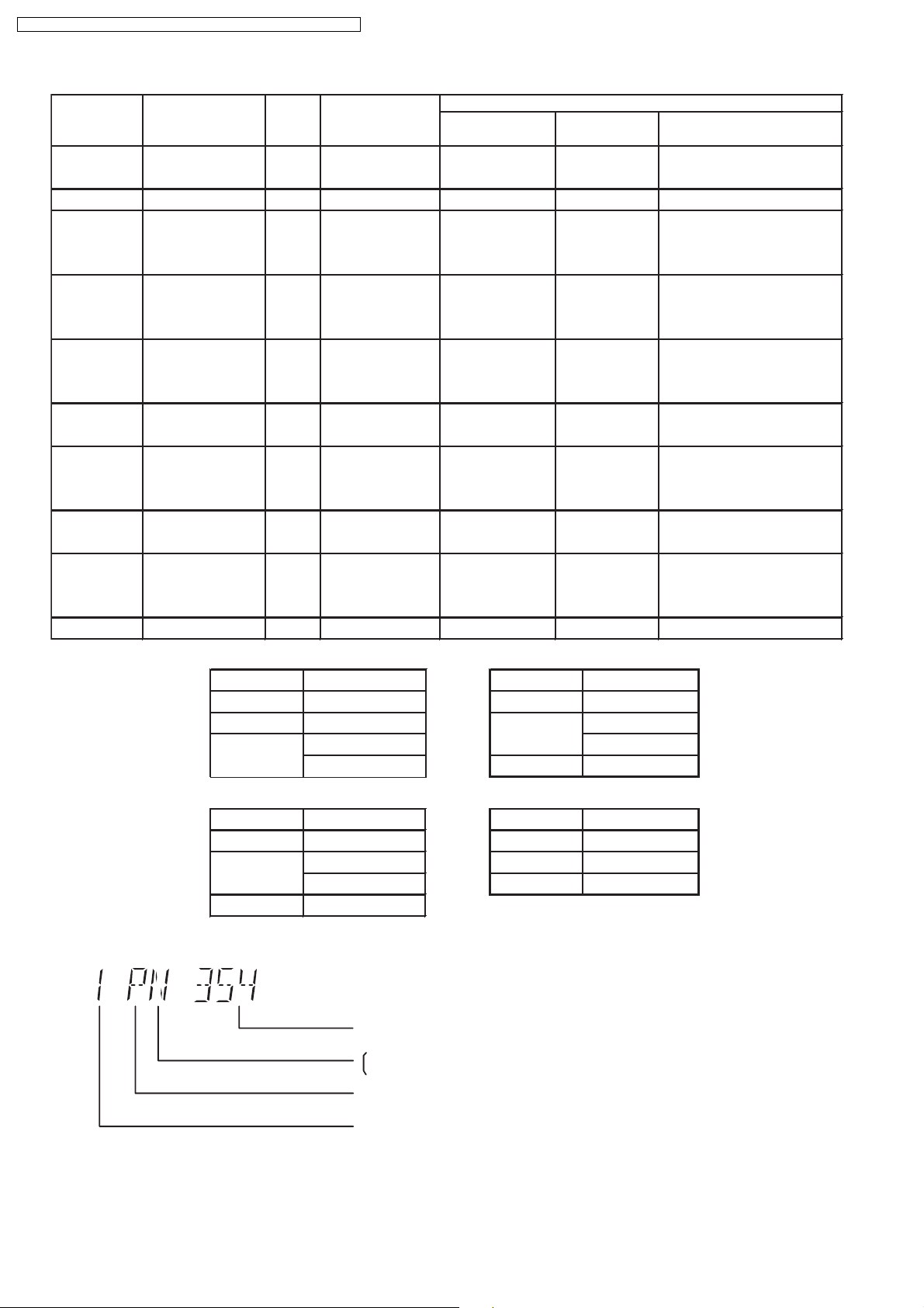
SA-PT150GC / SA-PT150G CP / SA-PT150GCS / SA-PT150G CT / SA-PT150GS
Model Series Country Region
Region
Code
P, PC, PX USA, Canada, PX NTSC (*A)
TV Broadcasting
System
NTSC1
Signal System Region Display
(Default) (Default)
Product
OSD Menu Language
English, Spanish, Canadian
French
(S) Japan 2 NTSC NTSC (*A) 2PN Japanese, English
English, French, German,
E Europe 2 PAL PAL (*C)
Spanish, Polish, Russian,
Czech, Hungarian
English, French, German,
EB, EG
Europe
PAL (*C)PAL2
Italian, Spanish, Polish,
Swedish, Dutch
English, French, German,
GC, GS
Middle East
PAL (*C)PAL2
Spanish, Polish, Russian,
Czech, Hungarian
GCS, GD, South East Asia, PAL English, Traditional Chinese
GT, GCT Korea, Taiwan NTSC
New Zealand,
Australia
PL, GCP, LB
Central/South/
Latin America Brazilian Portuguese
3 NTSC (*B)
4GN
NTSC4
PAL (*C)PAL
NTSC (*D) 4PN
English, French, German,
Italian, Spanish, Polish,
Swedish, Dutch
English, Spanish, French,
English, French, German,
EE CIS
PAL (*C)SECAM5
Spanish, Polish, Russian,
Czech, Hungarian
GK China 6 PAL NTSC (*B) 6PN English, Simplified Chinese
Explanation of Display
NTSC (*A) NTSC (*B)
Source Output Source Output
Screen Saver NTSC Screen Saver NTSC
NTSC disc NTSC
PAL disc
PAL (*C) NTSC (*D)
Source Output Source Output
Screen Saver PAL Screen Saver NTSC
NTSC disc
PAL disc PAL
PAL (DVD-V) PAL60
NTSC (DVD-A/VCD) PAL disc PAL60
PAL60 (default) NTSC disc NTSC
NTSC PAL disc NTSC
Individual Model Code
N: If NTSC disc is played, NTSC output.
6: If NTSC disc is played, PAL60 output.
can play PAL disc
NTSC disc
NTSC (default)
Region code
Figure 2
26
8.2.4. Service Mode Table 4
SA-PT150GC / SA-PT150G CP / SA-PT150GCS / SA-PT150G CT / SA-PT150GS
Mode Name
DVD
Module P.C.B.
firmware
version display
CPPM/CRM
Keys Check
DVD
Module P.C.B.
Reset
Item
Description
DVD Module P.C.B. firmware version
is displayed on the FL Display.
The firmware version can be updated
using recovery disc.
Note: It is necessary to check for
firmware version before carrying out
the version up using the disc.
CPPM/CRM refers to the Content
Protection for Recordable Media and
Pre-Recorded Media. It displays the
existence of the keys as "1" or "0".
OK: Existing of keys.
NG: Non existing of keys.
To reset DVD Module P.C.B.
This process is used when the DVD
Module P.C.B. or FLASH ROM
IC is replaced with a new one.
FL Display
Region No.: 0-8
0: NG
0: NG
1: OK
1: OK
System
controller
version
Destination
System controller
generation
Key Operation
Front Key
In STOP (no disc)
mode, press [STOP]
button on the main unit,
and [8] button on the
remote control unit.
Cancelled automatically
5 seconds later.
In STOP (no disc)
mode, press [STOP]
button on the main unit,
and [EQ] button on the
remote control unit.
Cancelled automatically
5 seconds later.
While in initialization
mode, press & hold
[STOP] button on the main
unit, follow by [ENTER]
button on the remote
control unit.
Cancelled automatically
5 seconds later.
27
SA-PT150GC / SA-PT150G CP / SA-PT150GCS / SA-PT150G CT / SA-PT150GS
8.2.5. Service Mode Table 5
Timer 1 check
Timer 1 reset
Item
DescriptionMode Name
Timer 1 check
Laser operation timer is measured
separately for DVD laser and CD laser.
FL Display sequence:
Display 1 2.
Timer 1 reset
Laser operation timer of both DVD
laser and CD laser is reset all at once.
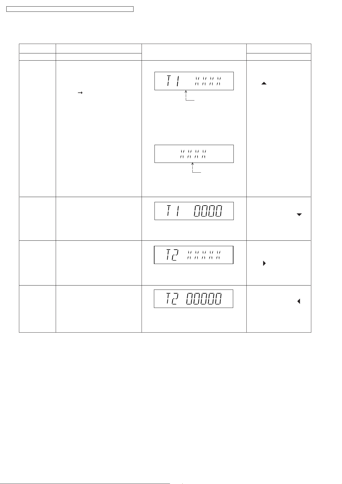
FL Display
(Display 1)
DVD laser usage time
Shown to the above is DVD laser usage
time, and to the below is CD laser usage
time.
Time is shown in 4 digits of decimal notation
in a unit of 10 hours.
"0000" will follow "9999". (DVD laser)
(Display 2)
CD laser usage time
Time is shown in 4 digits of decimal notation
in a unit of 10 hours.
"0000" will follow "9999". (CD laser)
Time is shown in 4 digits of decimal notation
in a unit of 10 hours.
It will clear to "0000" upon reset.
Key Operation
Front Key
In STOP (no disc)
mode, press [STOP]
button on the main unit,
and [ ] button on the
remote control unit.
Cancelled automatically
5 seconds later.
Press [FL Display] button for
next page of FL Display.
While displaying Timer 1
data, press [STOP] button
on the main unit, and [ ]
button on the remote
control unit.
Cancelled automatically
5 seconds later
Timer 2 check
Timer 2 reset
Timer 2 check
Spindle motor operation timer
Timer 2 reset
Spindle motor operation timer
Time is shown in 5 digits of decimal notation in
a unit of 1 hour.
"00000" will follow "99999".
Time is shown in 5 digits of decimal notation in
a unit of 1 hour.
It will be cleared to "00000" upon activating
this.
In STOP (no disc)
mode, press [STOP]
button on the main unit,
and [ ] button on the
remote control unit.
Cancelled automatically
5 seconds later.
While displaying Timer 2
data, press [STOP] button
on the main unit, and [ ]
button on the remote
control unit.
Cancelled automatically
5 seconds later.
28
Note: Press "FL DISPLAY" button on remote
control unit for next page display.
SA-PT150GC / SA-PT150G CP / SA-PT150GCS / SA-PT150G CT / SA-PT150GS
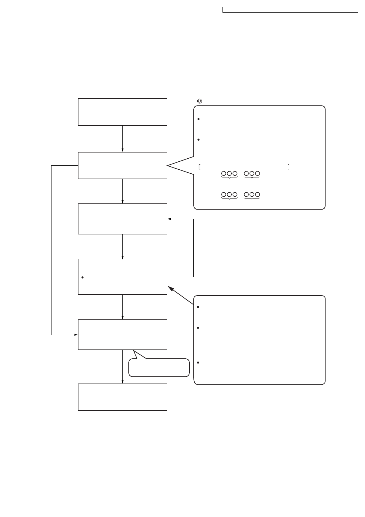
8.2.6. Optical Pick-up Self-Diagnosis
The optical pickup self-diagnosis function and tilt adjustment check function have been included in this unit. When repairing, use
the following procedure for effective self-diagnosis and tilt adjustment. Be sure to use the self-diagnosis function before replacing
the optical pickup when "NO DISC" is displayed. As a guideline, you should replace the optical pickup when the value of the laser
drive current is more than 55.
Note:
Press the power button to turn on the power, and check the value within three minutes before the unit warms up. (Otherwise,
the result will be incorrect.)
"NO DISC" is displayed, unit
does not play smoothly, etc.
Use the optical pickup self-diagnosis function.
Method: With no disc in the main unit:
· Press the "FUNCTIONS" button on the remote
control unit while pressing the "STOP"
button on the main unit. (DVD)
·Press the "3" button on the remote
control unit while pressing the "STOP"
button on the main unit. (CD)
Check the laser drive current.
Value is 23 (DVD),
34 (CD) or less.
Replace the optical pickup.
(Refer to the section "OPTICAL
PICKUP REPLACEMENT
PROCEDURE" in this Guide.)
Check the laser drive current
after replacement.
Write the present value into the
unit if it is 23 (DVD), 34 (CD) or
less.
Do the optical pickup tilt
adjustment. (Refer to the section
"TILT ADJUSTMENT" in this
Guide.)
Value is more than
23 (DVD), 34 (CD).
Display content (display1/display2)
/
LDD (DVD)
Factory setting Present value
LDC (CD)
/
Factory setting Present value
Replace with a new optical pickup if the present
value is more than 23 (DVD), 34 (CD).
Cause: Damage due to static electricity
during replacement.
Method: With no disc in the main unit:
·Press the "FUNCTIONS" button on the remote
control unit while pressing the "STOP"
button on the main unit. (DVD)
·Press the "3" button on the remote
control unit while pressing the "STOP"
button on the main unit. (CD)
Use the tilt adjustment
check function.
Initialize the main unit.
Writing method:
·Press the "PAUSE" button on the remote
control unit while pressing the "STOP"
button on the main unit.
Note: Press "FL DISPLAY" button on remote
control unit for next page display.
29
SA-PT150GC / SA-PT150G CP / SA-PT150GCS / SA-PT150G CT / SA-PT150GS
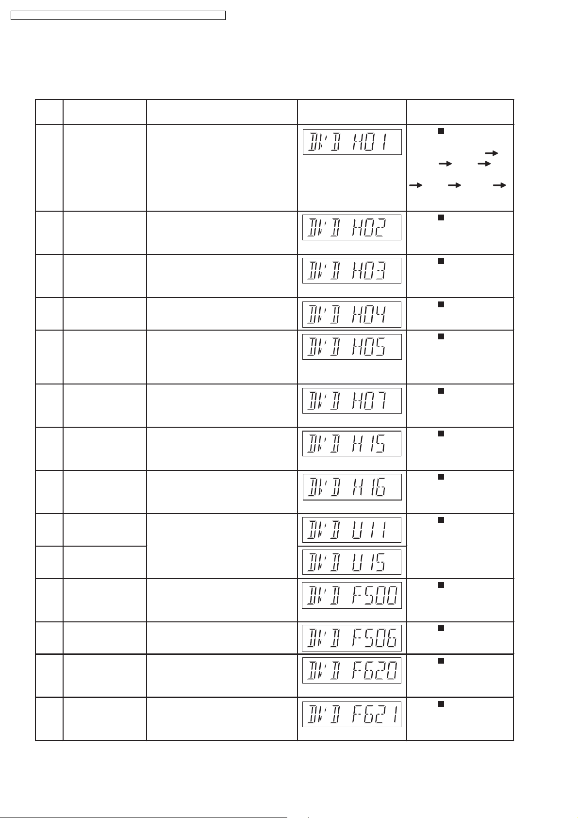
8.3. DVD Self Diagnostic Function-Error Code
8.3.1. Mechanism Error Code Table
Error
Diagnosis Contents Description of error Automatic FL Display Remarks
Code
H01 Tray loading error The tray opening and closing is Press [ STOP] on
abnormal. CLOSE and OPEN of the main unit for next error.
tray cannot be carried out properly. (OPEN time: OPEN
Loading motor error, DV5 LSI IC CLOSE OPEN
(IC8001) error. H01 at CLOSE: CLOSE
OPEN CLOSE
H01)
H02 Spindle servo error The spindle servo/motor is abnormal. Press [ STOP] on
The FG pulse is abnormal. CLV servo main unit for next error.
error.
H03 Traverse servo error The traverse is abnormal. (Traverse Press [ STOP] on
servo, DV5 LSI IC (IC8001), TRV main unit for next error.
motor error.)
H04 Tracking servo error Tracking coil NG (OPU unit Press [ STOP] on
abnormal), DV5 LSI IC (IC8001) main unit for next error.
error.
H05 Seek time out error It is not possible to access the disc. Press [ STOP] on
TOC cannot read. Abnormal disc etc. main unit for next error.
Pickup abnormal or disk is dirty.
(TRV motor error, DV5 LSI IC
(IC8001) error.)
H07 Driver IC thermal The spindle motor is abnormal. (short Press [ STOP] on
shut down between brushes) main unit for next error.
H15 Disc tray open The disc tray cannot be opened & it Press [ STOP] on
detection switch closes spontaneously. main unit for next error.
failure
H16 Disc tray close The disc tray cannot be closed & it Press [ STOP] on
detection switch opens spontaneously. main unit for next error.
failure
U11 Focus servo error Focus coil, FE signal error. Press [ STOP] on
main unit for next error.
(Unfinalized DVD-R
U15 Unfinalized DVD-R is likely to beocme U11.)
F500 DSC error DV5 LSI IC (IC8001) stops in the Press [ STOP] on
occurance of servo error (startup, main unit for next error.
focus error, etc)
F506 Invalid media Disc is flipped over, TOC unreadable, Press [ STOP] on
incompatible disc. main unit for next error.
F620 OPU unit Laser protection at high temperature. Press [ STOP] on
abnormality main unit for next error.
temperature
F621 OPU unit Laser protection at circuit failure. Press [ STOP] on
circuitry main unit for next error.
temperature
30
 Loading...