

Panasonic SAAK-980-PU Service manual
PSG0905029CE
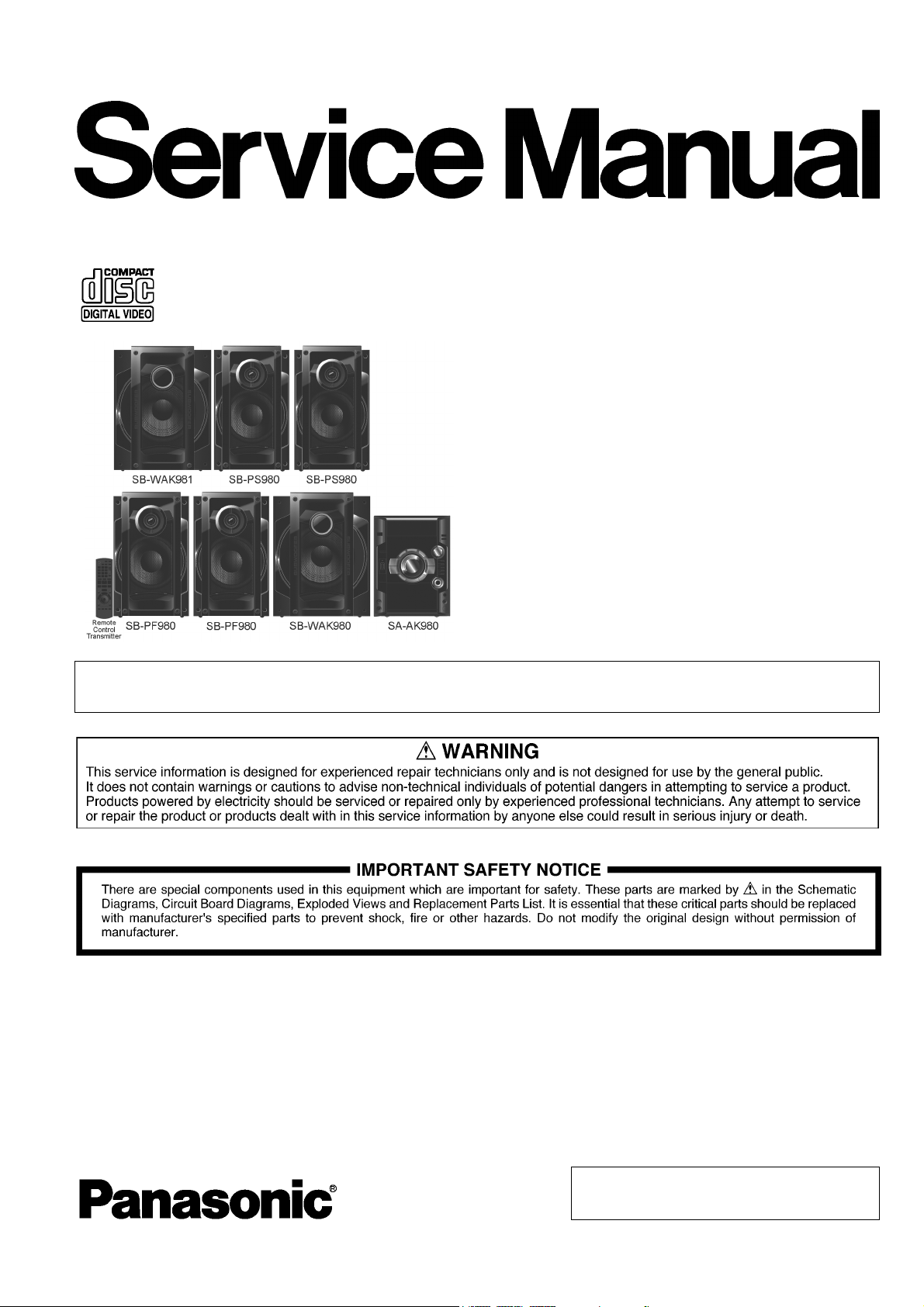
CD Stereo System
Model No. SA-AK980PU
Product Color: (K)...Black Type
Notes: This model’s CD Mechanism Unit (CR14C). Please refer to the Original Service Manual
(Order No. MD0805031CE) for this CD Mechanism Unit.
TABLE OF CONTENTS
PAG E PAG E
1 Safety Precautions ----------------------------------------------- 4
1.1. General Guidelines---------------------------------------- 4
1.2. Before Use -------------------------------------------------- 4
1.3. Caution For Fuse Replacement------------------------ 4
1.4. Before Repair and Adjustment ------------------------- 5
1.5. Protection Circuitry ---------------------------------------- 5
1.6. Safety Parts Information----------------------------------5
2Warning--------------------------------------------------------------6
2.1. Prevention of Electrostatic Discharge (ESD)
to Electrostatic Sensitive (ES) Devices--------------- 6
2.2. Precaution of Laser Diode -------------------------------7
2.3. Service caution based on Legal restrictions -------- 8
© Panasonic Corporation 2009. All rights reserved.
Unauthorized copying and distribution is a violation
of law.

2.4. Handling Precautions for Traverse Unit --------------9
3 Service Navigation---------------------------------------------- 11
3.1. Service Information -------------------------------------- 11
4 Specifications ---------------------------------------------------- 12
5 Location of Controls and Components------------------ 13
5.1. Main Unit Key Button Operation---------------------- 13
5.2. Remote Control Key Button Operation ------------- 14
5.3. Disc Information ------------------------------------------15
6 Self-Diagnosis and Special Mode Setting -------------- 16
6.1. Doctor Mode Summary Table -------------------------16
6.2. Doctor Mode Table--------------------------------------- 17
6.3. Service Mode Summary Table------------------------ 22
6.4. Service Mode Table-------------------------------------- 23
6.5. Reliability Test Mode (CD Mechanism Unit
CR14C) ----------------------------------------------------- 25
6.6. Error Code Table ----------------------------------------- 26
7 Troubleshooting Guide---------------------------------------- 28
7.1. Jupiter USB ------------------------------------------------ 28
7.2. Troubleshooting Guide---------------------------------- 29
7.3. Troubleshooting Guide for F61 and/or F76 -------- 31
8 Service Fixture & Tools --------------------------------------- 36
8.1. Service Tools and Equipment------------------------- 36
9 Disassembly and Assembly Instructions---------------37
9.1. Disassembly Flow Chart-------------------------------- 39
9.2. Main Components and P.C.B. Locations ----------- 40
9.3. Disassembly of Top Cabinet--------------------------- 41
9.4. Disassembly of CD Mechanism Unit (CR14C) --- 42
9.5. Disassembly of Rear Panel----------------------------43
9.6. Disassembly of Fan Unit ------------------------------- 44
9.7. Disassembly of Front Panel Assembly ------------- 45
9.8. Disassembly of Mic P.C.B. ----------------------------- 47
9.9. Disassembly of Panel P.C.B. -------------------------- 48
9.10. Disassembly of Dynamic Bass Knob &
Dynamic Bass Button Unit ----------------------------- 49
9.11. Disassembly of Memory P.C.B. ----------------------- 51
9.12. Disassembly of MPort/Headphone P.C.B. --------- 52
9.13. Disassembly of CD Servo P.C.B.--------------------- 53
9.14. Disassembly of D-Amp P.C.B. & Fan --------------- 54
9.15. Replacement of Audio Digital Amp IC
(IC5400) ---------------------------------------------------- 56
9.16. Replacement of Audio Digital Amp IC
(IC5000) ---------------------------------------------------- 57
9.17. Replacement of Audio Digital Amp IC
(IC5200) ---------------------------------------------------- 58
9.18. Replacement of Audio Digital Amp IC
(IC5300) ---------------------------------------------------- 59
9.19. Disassembly of Main P.C.B. ---------------------------60
9.20. Disassembly of SMPS P.C.B.------------------------- 61
9.21. Replacement of Switching Regulator IC
(IC5701) ---------------------------------------------------- 62
9.22. Replacement of Rectifier Diode (D5702)----------- 63
9.23. Replacement of Regulator Diode (D5801)--------- 65
9.24. Replacement of Regulator Diode (D5802)--------- 66
9.25. Replacement of Regulator Diode (D5803)--------- 67
9.26. Disassembly of AC Inlet P.C.B. ----------------------- 68
9.27. Disassembly of Jupiter P.C.B.-------------------------69
9.28. Disassembly of Voltage Selector P.C.B.------------ 70
9.29. Replacement of Traverse Unit Assembly ---------- 71
9.30. Disassembly of CD Lid---------------------------------- 73
10 Service Position ------------------------------------------------- 74
10.1. Checking and Repairing of Main P.C.B. ------------74
10.2. Checking and Repairing of Panel P.C.B., Mic
P.C.B., Jupiter P.C.B. and MPort/Headphone
P.C.B. ------------------------------------------------------- 74
10.3. Checking and Repairing of D-Amp P.C.B.--------- 75
10.4. Checking and Repairing of SMPS P.C.B. and
AC Inlet P.C.B.-------------------------------------------- 76
11 Voltage & Waveform Chart ---------------------------------- 77
11.1. CD Servo P.C.B. ----------------------------------------- 77
11.2. Main P.C.B. (1/3)----------------------------------------- 78
11.3. Main P.C.B. (2/3)----------------------------------------- 79
11.4. Main P.C.B. (3/3)----------------------------------------- 80
11.5. Panel P.C.B.----------------------------------------------- 80
11.6. D-Amp P.C.B.--------------------------------------------- 81
11.7. Jupiter P.C.B. (1/3) -------------------------------------- 82
11.8. Jupiter P.C.B. (2/3) -------------------------------------- 83
11.9. Jupiter P.C.B. (3/3) -------------------------------------- 84
11.10. Mic P.C.B.-------------------------------------------------- 84
11.11. SMPS P.C.B. ---------------------------------------------- 85
11.12. Waveform Table (1/3)----------------------------------- 86
11.13. Waveform Table (2/3)----------------------------------- 87
11.14. Waveform Table (3/3)----------------------------------- 88
12 Illustration of ICs, Transistor and Diode---------------- 89
13 Block Diagram --------------------------------------------------- 90
13.1. CD Servo Block Diagram ------------------------------ 90
13.2. Jupiter Block Diagram ---------------------------------- 91
13.3. Main(1/2) Block Diagram ------------------------------ 92
13.4. Main(2/2) Block Diagram ------------------------------ 93
13.5. Panel / Mport/Headphone / Mic / Memory
Block Diagram-------------------------------------------- 94
13.6. D-Amp Block Diagram---------------------------------- 95
13.7. SMPS / AC Inlet / Voltage Selector Block
Diagram ---------------------------------------------------- 96
14 Wiring Connection Diagram -------------------------------- 97
15 Schematic Diagram Notes ----------------------------------- 98
16 Schematic Diagram -------------------------------------------- 99
16.1. CD Servo Circuit ----------------------------------------- 99
16.2. Main Circuit (1/6)----------------------------------------100
16.3. Main Circuit (2/6)----------------------------------------101
16.4. Main Circuit (3/6)----------------------------------------102
16.5. Main Circuit (4/6)----------------------------------------103
16.6. Main Circuit (5/6)----------------------------------------104
16.7. Main Circuit (6/6)----------------------------------------105
16.8. Panel Circuit (1/2) --------------------------------------106
16.9. Panel Circuit (2/2) --------------------------------------107
16.10. Memory / Mport/Headphone / Mic Circuit---------108
16.11. D-Amp Circuit (1/2)-------------------------------------109
16.12. D-Amp Circuit (2/2)-------------------------------------110
16.13. Jupiter Circuit (1/5) ------------------------------------- 111
16.14. Jupiter Circuit (2/5) ------------------------------------- 112
16.15. Jupiter Circuit (3/5) ------------------------------------- 113
16.16. Jupiter Circuit (4/5) ------------------------------------- 114
16.17. Jupiter Circuit (5/5) ------------------------------------- 115
16.18. SMPS Circuit (1/2)-------------------------------------- 116
16.19. SMPS Circuit (2/2)-------------------------------------- 117
16.20. AC Inlet / Voltage selector Circuit------------------- 118
17 Printed Circuit Board-----------------------------------------119
17.1. CD Servo / Jupiter P.C.B.----------------------------- 119
17.2. Main P.C.B. -----------------------------------------------120
17.3. Panel / Memory / Mport/Headphone / Mic
P.C.B. ------------------------------------------------------ 121
17.4. D-Amp P.C.B. -------------------------------------------- 122
2

17.5. SMPS / AC Inlet / Voltage Selector P.C.B. ------- 123
18 Terminal Function of ICs------------------------------------124
18.1. IC2801 (RFKWMAK980PU): IC
Microprocessor------------------------------------------ 124
18.2. IC6601(C0HBB0000057): IC FL Driver -----------125
19 Exploded View and Replacement Parts List --------- 126
19.1. Exploded View and Mechanical Replacement
Parts List-------------------------------------------------- 126
19.2. Electrical Replacement Part List--------------------131
3
1 Safety Precautions
1.1. General Guidelines
1. When servicing, observe the original lead dress. If a short circuit is found, replace all parts which have been overheated or
damaged by the short circuit.
2. After servicing, see to it that all the protective devices such as insulation barriers, insulation papers shields are properly
installed.
3. After servicing, carry out the following leakage current checks to prevent the customer from being exposed to shock hazards.
1.1.1. Leakage Current Cold Check
1. Unplug the AC cord and connect a jumper between the two prongs on the plug.
2. Measure the resistance value, with an ohmmeter, between the jumpered AC plug and each exposed metallic cabinet part on
the equipment such as screwheads, connectors, control shafts, etc. When the exposed metallic part has a return path to the
chassis, the reading should be between 1MΩ and 5.2MΩ.
When the exposed metal does not have a return path to the chassis, the reading must be
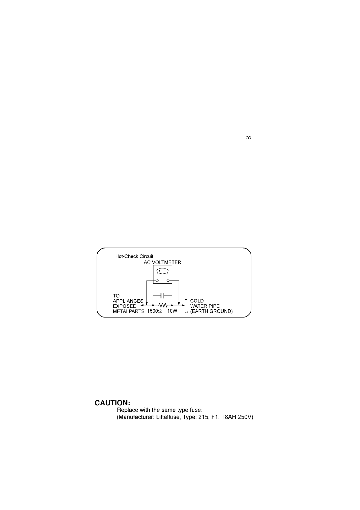
1.1.2. Leakage Current Hot Check
1. Plug the AC cord directly into the AC outlet. Do not use an isolation transformer for this check.
2. Connect a 1.5kΩ, 10 watts resistor, in parallel with a 0.15μF capacitors, between each exposed metallic part on the set and a
good earth ground such as a water pipe, as shown in Figure 1.
3. Use an AC voltmeter, with 1000 ohms/volt or more sensitivity, to measure the potential across the resistor.
4. Check each exposed metallic part, and measure the voltage at each point.
5. Reverse the AC plug in the AC outlet and repeat each of the above measurements.
6. The potential at any point should not exceed 0.75 volts RMS. A leakage current tester (Simpson Model 229 or equivalent)
may be used to make the hot checks, leakage current must not exceed 1/2 milliamp. In case a measurement is outside of the
limits specified, there is a possibility of a shock hazard, and the equipment should be repaired and rechecked before it is
returned to the customer.
Figure 1
1.2. Before Use
Be sure to disconnect the mains cord before adjusting the voltage selector.
Use a minus(-) screwdriver to set the voltage selector (on the rear panel) to the voltage setting for the area in which the unit will be
used. (If the power supply in your area is 110V ~ 127V or 220V ~ 240V, set to the “110V ~ 127V or 220V ~ 240V” position.)
Note that this unit will be seriously damaged if this setting is not made correctly. (There is no voltage selector for some countries,
the correct voltage is already set.)
1.3. Caution For Fuse Replacement
4
1.4. Before Repair and Adjustment
Disconnect AC power to discharge unit AC Capacitors as such (C5700, C5701, C5703, C5704, C5705, C5706, C5707) through a
10 Ω, 10 W resistor to ground.
Caution:
DO NOT SHORT-CIRCUIT DIRECTLY (with a screwdriver blade, for instance), as this may destroy solid state devices.
After repairs are completed, restore power gradually using a variac, to avoid overcurrent.
Current consumption at AC 110V~127V / 220V~240V, 50/60 Hz in NO SIGNAL mode volume minimal should be ~ 500 mA.
1.5. Protection Circuitry
The protection circuitry may have operated if either of the following conditions are noticed:
• No sound is heard when the power is turned on.
• Sound stops during a performance.
The function of this circuitry is to prevent circuitry damage if, for example, the positive and negative speaker connection wires are
“shorted”, or if speaker systems with an impedance less than the indicated rated impedance of the amplifier are used.
If this occurs, follow the procedure outlines below:
1. Turn off the power.
2. Determine the cause of the problem and correct it.
3. Turn on the power once again after one minute.
Note:
When the protection circuitry functions, the unit will not operate unless the power is first turned off and then on again.
1.6. Safety Parts Information
Safety Parts List:
There are special components used in this equipment which are important for safety.
These parts are marked by in the Schematic Diagrams & Replacement Parts List. It is essential that these critical parts
should be replaced with manufacturer’s specified parts to prevent shock, fire or other hazards. Do not modify the original design
without permission of manufacturer.
Table 1
Safety Ref. No. Part No. Part Name & Description Remarks
6 REXX0687-1 BLUE WIRE (VOLT SELECTOR-
13 REZX0024-1 BLACK WIRE (AC-SMPS)
14 REZX0023-1 RED WIRE (AC SMPS)
15 REXX0686-1 WHITE (VOLT SELECTOR-SMPS)
22 RGRX0070ADA REAR PANEL
41 RKMX0144A-K TOP CABINET
340 RAEX0190A-V TRAVESER ASS’Y (W/O CD SERVO)
A2 K2CQ2CA00007 AC CORD
A3 RQTX0273-M O/I BOOK (En/Sp)
DZ5701 ERZV10V511CS ZNR
S5701 K0ABCA000007 SW VOLTAGE SELECTOR
L5702 ELF22V035B LINE FILTER
T2900 G4D1A0000117 SWITCHING TRANSFORMER
T5701 ETS48AB116AC MAIN TRANSFORMER
T5751 ETS19AB256AG SUB TRANSFORMER
PC5701 B3PBA0000402 PHOTO COUPLER
PC5702 B3PBA0000402 PHOTO COUPLER
PC5720 B3PBA0000402 PHOTO COUPLER
PC5799 B3PBA0000402 PHOTO COUPLER
F1 K5D802BNA005 FUSE
FP2901 K5G4013A0001 FUSE PROTECTOR
TH5702 D4CAA2R20001 THERMISTOR
TH5860 D4CC11040013 THERMISTOR
P5701 K2AA2B000017 AC INLET
C5700 F1BAF1020020 1000pF
C5701 F0CAF334A087 0.33uF
C5703 F0C2H1040001 0.1uF 500V
C5704 F1BAF1020020 1000pF
C5705 F1BAF1020020 1000pF
C5706 F1BAF1020020 1000pF
C5707 F1BAF1020020 1000pF
PCB8 REPX0714E SMPS P.C.B.
PCB9 REPX0714E AC INLET P.C.B.
PCB10 REPX0714E VOLTAGE SELECTOR P.C.B.
SMPS)
5

2Warning
2.1. Prevention of Electrostatic Discharge (ESD) to Electrostatic Sensitive (ES) Devices
Some semiconductor (solid state) devices can be damaged easily by static electricity. Such components commonly are called Electrostatically Sensitive (ES) Devices. Examples of typical ES devices are integrated circuits and some field-effect transistors and
semiconductor "chip" components. The following techniques should be used to help reduce the incidence of component damage
caused by electrostatic discharge (ESD).
1. Immediately before handling any semiconductor component or semiconductor-equipped assembly, drain off any ESD on your
body by touching a known earth ground. Alternatively, obtain and wear a commercially available discharging ESD wrist strap,
which should be removed for potential shock reasons prior to applying power to the unit under test.
2. After removing an electrical assembly equipped with ES devices, place the assembly on a conductive surface such as aluminum foil, to prevent electrostatic charge buildup or exposure of the assembly.
3. Use only a grounded-tip soldering iron to solder or unsolder ES devices.
4. Use only an anti-static solder removal device. Some solder removal devices not classified as “anti-static (ESD protected)” can
generate electrical charge sufficient to damage ES devices.
5. Do not use freon-propelled chemicals. These can generate electrical charges sufficient to damage ES devices.
6. Do not remove a replacement ES device from its protective package until immediately before you are ready to install it. (Most
replacement ES devices are packaged with leads electrically shorted together by conductive foam, aluminum foil or comparable conductive material).
7. Immediately before removing the protective material from the leads of a replacement ES device, touch the protective material
to the chassis or circuit assembly into which the device will be installed.
Caution:
Be sure no power is applied to the chassis or circuit, and observe all other safety precautions.
8. Minimize bodily motions when handling unpackaged replacement ES devices. (Otherwise harmless motion such as the
brushing together of your clothes fabric or the lifting of your foot from a carpeted floor can generate static electricity (ESD) suf-
ficient to damage an ES device).
6
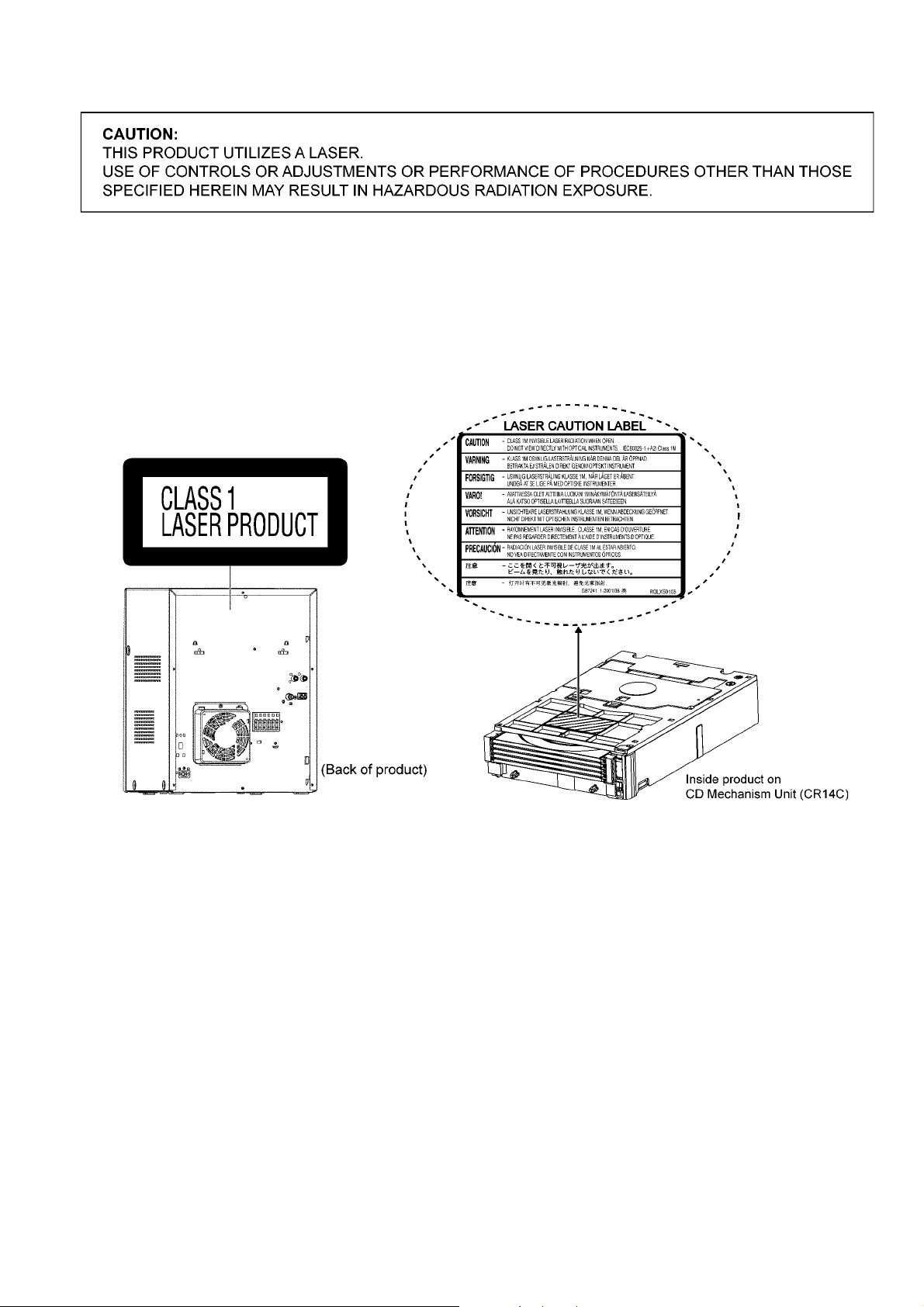
2.2. Precaution of Laser Diode
Caution:
This product utilizes a laser diode with the unit turned “on”, invisible laser radiation is emitted from the pickup lens.
Wavelength: 795 nm (CD)
Maximum output radiation power from pickup: 100 μW/VDE
Laser radiation from the pickup unit is safety level, but be sure the followings:
1. Do not disassemble the pickup unit, since radiation from exposed laser diode is dangerous.
2. Do not adjust the variable resistor on the pickup unit. It was already adjusted.
3. Do not look at the focus lens using optical instruments.
4. Recommend not to look at pickup lens for a long time.
7

2.3. Service caution based on Legal restrictions
2.3.1. General description about Lead Free Solder (PbF)
The lead free solder has been used in the mounting process of all electrical components on the printed circuit boards used for this
equipment in considering the globally environmental conservation.
The normal solder is the alloy of tin (Sn) and lead (Pb). On the other hand, the lead free solder is the alloy mainly consists of tin
(Sn), silver (Ag) and Copper (Cu), and the melting point of the lead free solder is higher approx.30 degrees C (86°F) more than that
of the normal solder.
Definition of PCB Lead Free Solder being used
The letter of “PbF” is printed either foil side or components side on the PCB using the lead free solder.
(See right figure)
Service caution for repair work using Lead Free Solder (PbF)
• The lead free solder has to be used when repairing the equipment for which the lead free solder is used.
(Definition: The letter of “PbF” is printed on the PCB using the lead free solder.)
• To put lead free solder, it should be well molten and mixed with the original lead free solder.
• Remove the remaining lead free solder on the PCB cleanly for soldering of the new IC.
• Since the melting point of the lead free solder is higher than that of the normal lead solder, it takes the longer time to melt the
lead free solder.
• Use the soldering iron (more than 70W) equipped with the temperature control after setting the temperature at 350±30 degrees
C (662±86°F).
Recommended Lead Free Solder (Service Parts Route.)
• The following 3 types of lead free solder are available through the service parts route.
RFKZ03D01K-----------(0.3mm 100g Reel)
RFKZ06D01K-----------(0.6mm 100g Reel)
RFKZ10D01K-----------(1.0mm 100g Reel)
Note
* Ingredient: tin (Sn), 96.5%, silver (Ag) 3.0%, Copper (Cu) 0.5%, Cobalt (Co) / Germanium (Ge) 0.1 to 0.3%
8
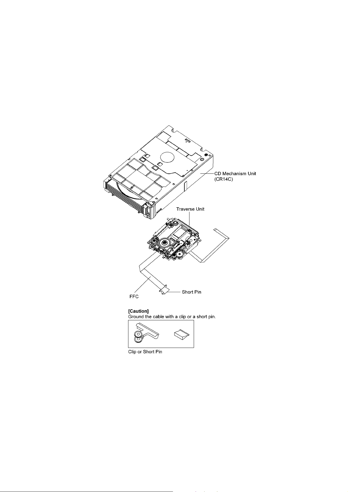
2.4. Handling Precautions for Traverse Unit
The laser diode in the optical pickup unit may break down due to static electricity of clothes or human body. Special care must be
taken avoid caution to electrostatic breakdown when servicing and handling the laser diode in the traverse unit.
2.4.1. Cautions to Be Taken in Handling the Optical Pickup Unit
The laser diode in the optical pickup unit may be damaged due to electrostatic discharge generating from clothes or human body.
Special care must be taken avoid caution to electrostatic discharge damage when servicing the laser diode.
1. Do not give a considerable shock to the optical pickup unit as it has an extremely high-precise structure.
2. To prevent the laser diode from the electrostatic discharge damage, the flexible cable of the optical pickup unit removed
should be short-circuited with a short pin or a clip.
3. The flexible cable may be cut off if an excessive force is applied to it. Use caution when handling the flexible cable.
4. The antistatic FPC is connected to the new optical pickup unit. After replacing the optical pickup unit and connecting the flexible cable, cut off the antistatic FPC.
2.4.2. Grounding for electrostatic breakdown prevention
Some devices such as the DVD player use the optical pickup (laser diode) and the optical pickup will be damaged by static electricity in the working environment. Proceed servicing works under the working environment where grounding works is completed.
2.4.2.1. Worktable grounding
1. Put a conductive material (sheet) or iron sheet on the area where the optical pickup is placed, and ground the sheet.
9

2.4.2.2. Human body grounding
1. Use the anti-static wrist strap to discharge the static electricity form your body.
10

3 Service Navigation
3.1. Service Information
This service manual contains technical information which will allow service personnel’s to understand and service this model.
Please place orders using the parts list and not the drawing reference numbers.
If the circuit is changed or modified, this information will be followed by supplement service manual to be filed with original service
manual.
• CD Mechanism unit (CR14C):
1) This model uses CD Mechanism Unit (CR14C).
2) This service manual does not contain the following information on CD Mechanism Unit (CR14C)
- Schematic Diagram, Block Diagram and P.C.B. layout of CD Mechanism Unit (CR14C) P.C.B.
- Parts List for individual parts of CD Mechanism Unit (CR14C).
- Exploded View and Part List for individual parts of CD Mechanism Unit (CR14C).
Please refer to original service manual (Order No. MD0805031CE)
• Micro-processor, EEPROM & FLASH ROM IC:
1) The following components are supplied as an assembled part.
- Micro-processor IC, IC2801 (RFKWMAK980PU)
- EEPROM IC, IC2200 (RFKWEAK980PU)
- FLASH ROM IC, IC701 (RFKWFAK980PU)
Before replacement of micro-processor IC, please check the version no. It may need matching with ROM correction.
• Speaker system:
1) The information, please refer to original service manual, SB-AK980PU-K (PSG0905030CE)
11

4 Specifications
Q AMPLIFIER SECTION
RMS output power stereo mode
Front Ch (both channels driven) 125 W per channel (3 Ω), 1 kHz
Surround Ch (both channels driven)
125 W per channel (3 Ω), 1 kHz
Subwoofer Ch (2 channels) 250 W per channel (6 Ω), 100 Hz
Total RMS stereo mode power 1000 W
Q FM/AM TUNER, TERMINALS SECTION
Preset station FM 30 stations
AM 15 stations
Frequency Modulation (FM)
Frequency range 87.50 to 108.00 MHz (50 kHz step)
Antenna terminal(s) 75 Ω (unbalanced)
Amplitude Modulation (AM)
Frequency range 522 to 1629 kHz (9 kHz step)
520 to 1630 kHz (10 kHz step)
Aux input RCA pin jack
Music Port (front) jack
Sensitivity 100 mV, 4.7 kΩ
Terminal Stereo, 3.5 mm jack
Headphone jack
Terminal Stereo, 3.5 mm jack
Output level (CD, 1kHz, -20dB) 32 Ω (Max)
Mic jack
Sensitivity 0.7 mV, 1.2 kΩ
Terminal Mono, 3.5 mm jack (1 system)
Q DISC SECTION
Disc played (8 cm or 12 cm)
(1) CD-Audio (CD-DA)
(2) CD-R/RW (CD-DA, MP3* formatted disc)
(3) MP3*
* MPEG-1 Layer 3, MPEG-2 Layer 3
Pick up
Wavelength 795 nm(CD)
Audio output (Disc)
Number of channels 4.2 ch (FL, FR, SL, SR, SWx2)
FL = Front left channel
FR = Front right channel
SL = Surround left channel
SR = Surround right channel
SW = Subwoofer channel
Q USB SECTION
USB port
USB standard USB 2.0 full speed
Media file format support MP3 (*.mp3)
USB device file system FAT12/FAT16/FAT32
USB port power 500 mA (Max)
Bit rate 16 kbps to 320 kbps (P.B)
USB recording
Recording file format MP3 (*.mp3)
Bit rate 1x, max 4x (CD only)
USB recording speed 1000 mV ± 150 mV
USB recording speed 1x, 4x (CD only)
Recording file format MP3 (*.mp3)
Q MEMORY SECTION
Memory
Memory size 2 GB
Memory file format MP3 (*.mp3)
Memory recording
Recording file format MP3 (*.mp3)
Bit rate 128 kbps / 192 kbps / 320 kbps
Memory recording speed 1x, max 4x (CD only)
Q General
Power supply AC 110 to 127/220 to 240 V, 50/60 Hz
Power consumption 165 W
Dimensions (W x H x D) 250 mm x 333 mm x 326 mm
Mass 4.7 kg
Operating temperature range 0°C to +40°C
Operating humidity range 35 to 80% RH (no condensation)
Power consumption in
standby mode
Notes :
1. Specifications are subject to change without notice.
Mass and dimensions are approximate.
2. Total harmonic distortion is measured by the digital spectrum
analyzer.
Q System: SC-AK980PU-K Main Unit: SA-AK980PU-K
Front Speakers: SB-PF980PU-K
Surround Speakers: SB-PS980PU-K
Subwoofer 1 (with LEVEL control): SB-WAK980PU-K
Subwoofer 2: SB-WAK981PU-K
0.5 W (Approximate)
12
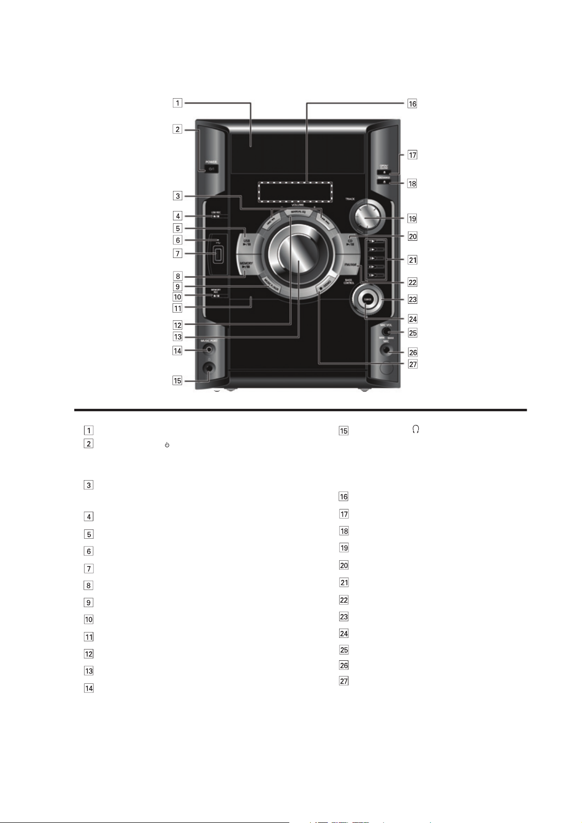
5 Location of Controls and Components
Avoid listening for
prolonged periods of time to
prevent hearing damage.
Excessive sound pressure from earphones and
headphones can cause hearing loss.
Plug type: Ø 3.5mm stereo (not included)
Headphone jack
Press to switch the unit from on to standby mode or vice versa.
In standby mode, the unit is still consuming a small amount of
power.
Standby/on switch (
Track skip or search, check program content, preset channel
selection, tuning function, time adjustment, timer operation,
manual EQ setting
/l, POWER)
Microphone jack
Stop playback, demonstration function
USB recording or pause
USB play or pause
USB recording indicator
USB port
Memory play or pause
Music port or AUC selection
Memory recording or pause
Remote control signal sensor
Manual EQ selection
Volume control
Music port jack
Display panel
Disc change
Tray skip function
Disc play or pause
Disc direct play
Tuner (FM/AM) Selection
Manual EQ’s bass control setting
D.BASS selection
Microphone volume control
Disc trays
Disc tray open or close
5.1. Main Unit Key Button Operation
13
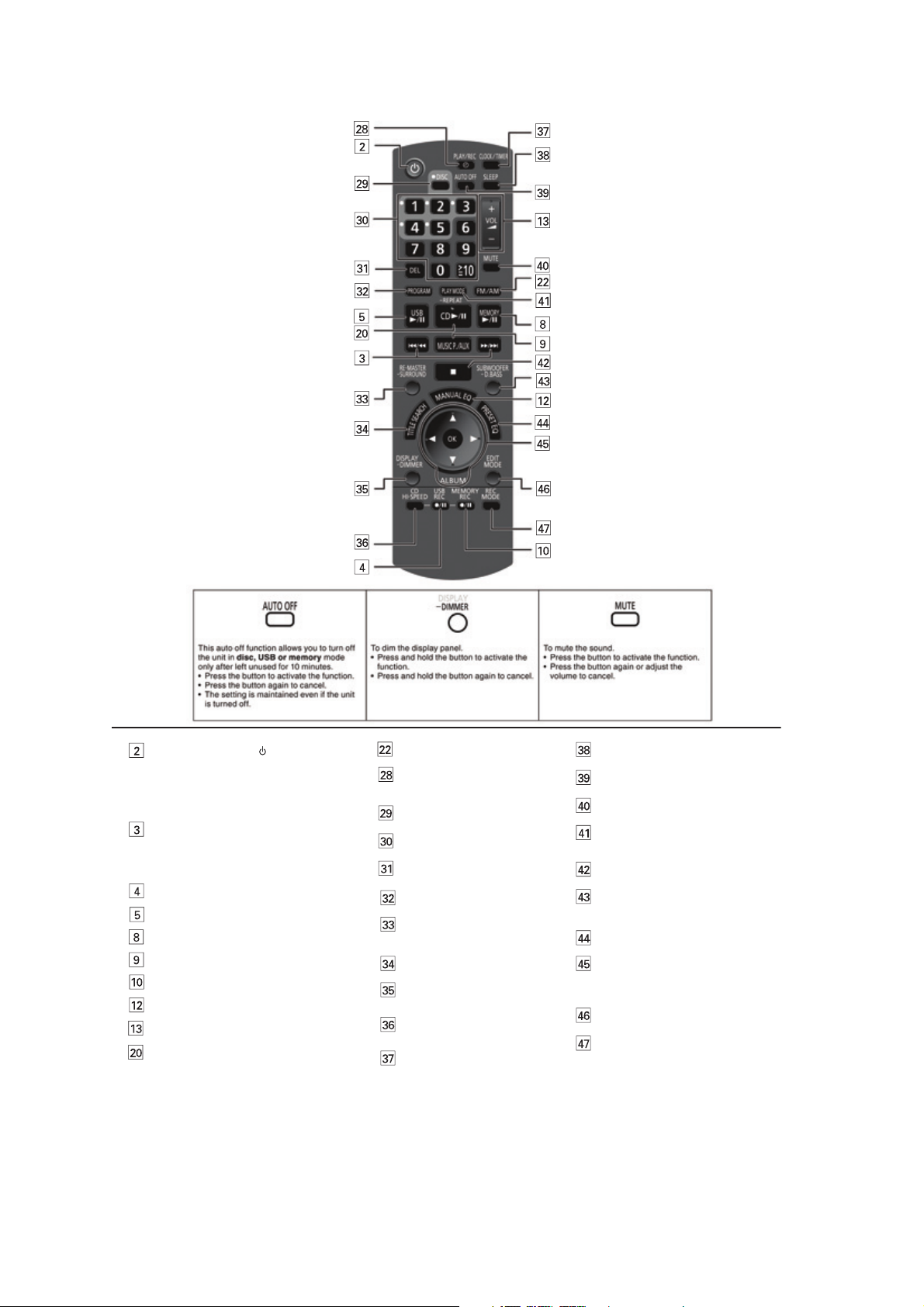
5.2. Remote Control Key Button Operation
Play timer recording timer
Setting
Disc selection
Numertic selection
Delete function
RE-MASTER selection
SURROUND sound selection
Title search function
Display function
Dimmer function
Program function
CD high-speed recording
function
Clock or timer setting
Sleep timer
Auto off function
Muting function
Play mode function
Repeat mode function
Subwoofer level selection
D.BASS selection
Preset EQ selection
Album selection
Confirm selection
Title search selection
Edit mode selection
Recording mode selection
Stop playback or program clear
Volume control
Tuner (FM/AM) Selection
USB recording or pause
USB play or pause
Memory play or pause
Music port or AUC selection
Memory recording or pause
Manual EQ selection
Press to switch the unit from on
to standby mode or vice versa.
In standby mode, the unit is still
consuming a small amount of power.
Standby/on switch (
/l, POWER)
Track skip or search, check program
content, preset channel selection,
tuning function, time adjustment,
timer operation, manual EQ setting
Disc play or pause
14
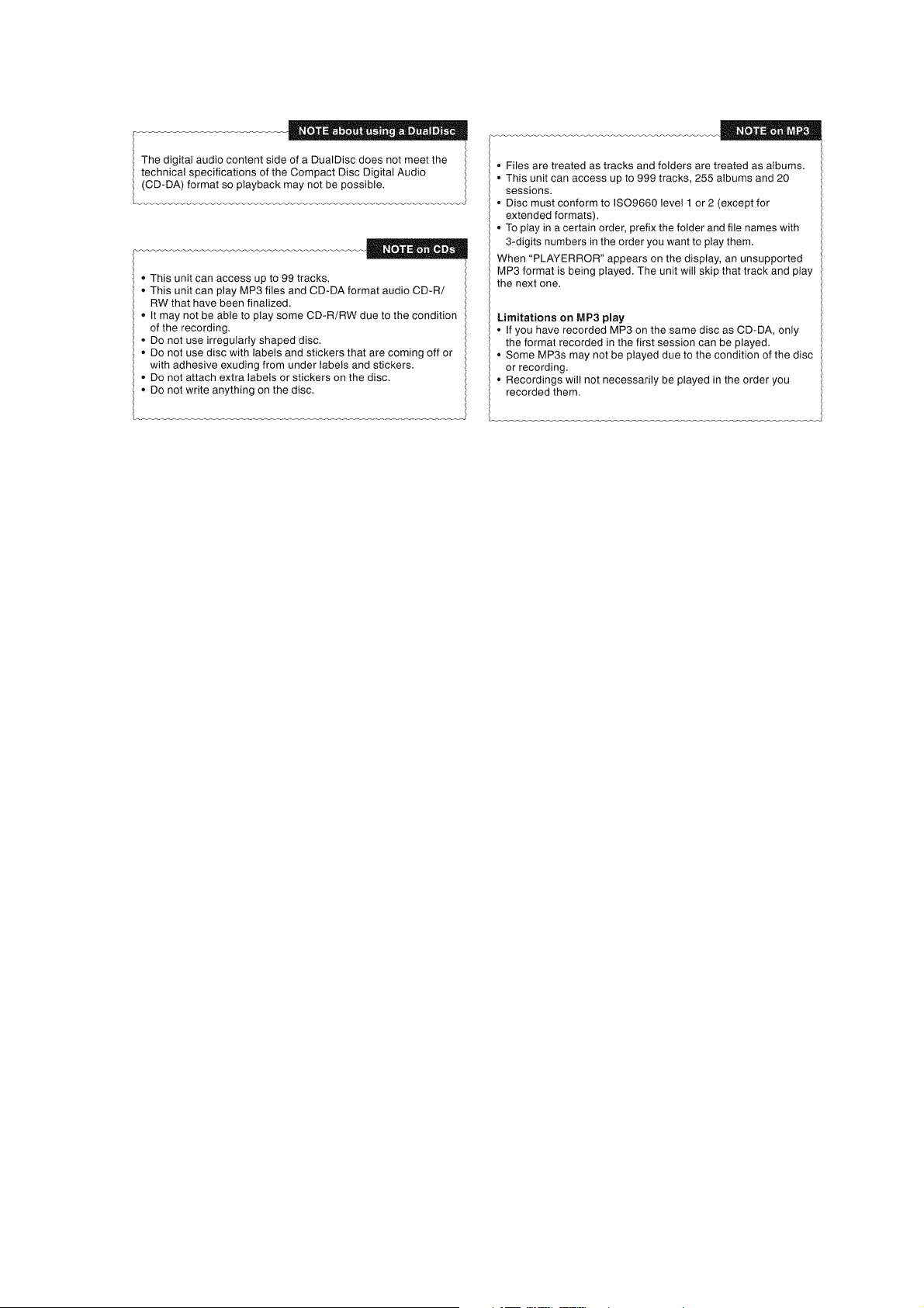
5.3. Disc Information
15
6 Self-Diagnosis and Special Mode Setting
This unit is equipped with features od self-diagnosis & special mode setting for checking the function & reliability.
Special Note: Checking of the reliability (ageing) & changer operation must be carry out to ensure good working condition in unit.
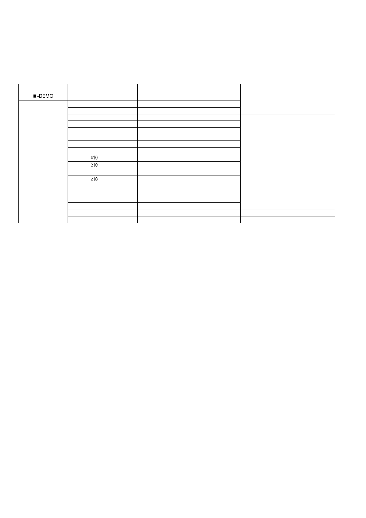
6.1. Doctor Mode Summary Table
Main unit buttons Remote control unit buttons Application Note
[]
Doctor Mode [DISPLAY/-DIMMER] Cold Start
[PLAYMODE/-REPEAT] Volume 30 Setting Check
[4], [7] Doctor Mode (Refer to the section “6.2.1 Doctor Mode
[2] Micro-P Version Display
[7] Volume 50 Setting Check (Refer to the section “6.2.2 Doctor Mode
[8] Volume 35 Setting Check
[9] Volume 0 Setting Check
[1] FL Display Check
[DEL] CD Open Test
[ ], [1], [1]
[ ], [1], [2]
[DISC] CR14 Changer Mechanism Check (Refer to the section “6.2.3 Doctor Mode
[ ], [9], [4]
[4] CD to USB Recording & Playing Inspection (Refer to the section “6.2.4 Doctor Mode
[5] CD to Memory Reading & Playing Inspection (Refer to the section “6.2.5 Doctor Mode
[EDIT MODE] Memory All Delete
[FM/AM] Tuner Inspection
[OK] Exit Inspection Mode
CR14 Reliability Test 1 (no retry)
CR14 Reliability Test 2 (with retry)
CR14 Error Late Display
Table 1” for more information.)
Table 2” for more information.)
Table 3” for more information.)
Table 4” for more information.)
Table 5” for more information.)
16
6.2. Doctor Mode Table
Below is the various special modes for checking:-
6.2.1. Doctor Mode Table 1
Item FL Display Key Operation
Mode Name Description Front Key
Doctor Mode To enter into Doctor
Mode.
Cold Start To activate cold start upon
next power up when
reset is execute the next
time.
In CD Mode:
1. Press [ ] button on main unit follow by [4] and [7] on remote control.
To exit Doctor Mode, press [OK] button on
remote control.
In Doctor Mode:
1. Press [DISPLAY/-DIMMER] button on
remote control.
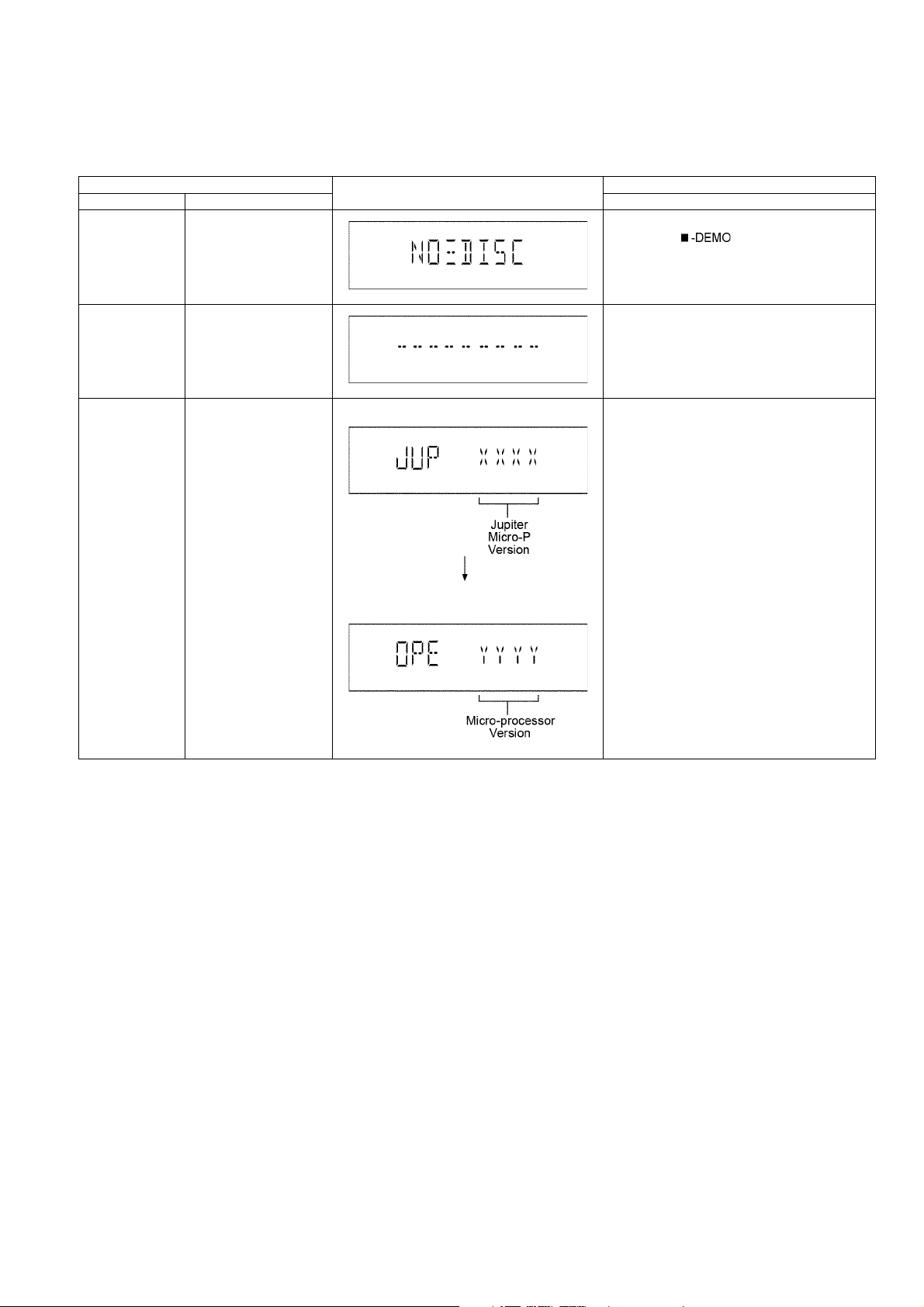
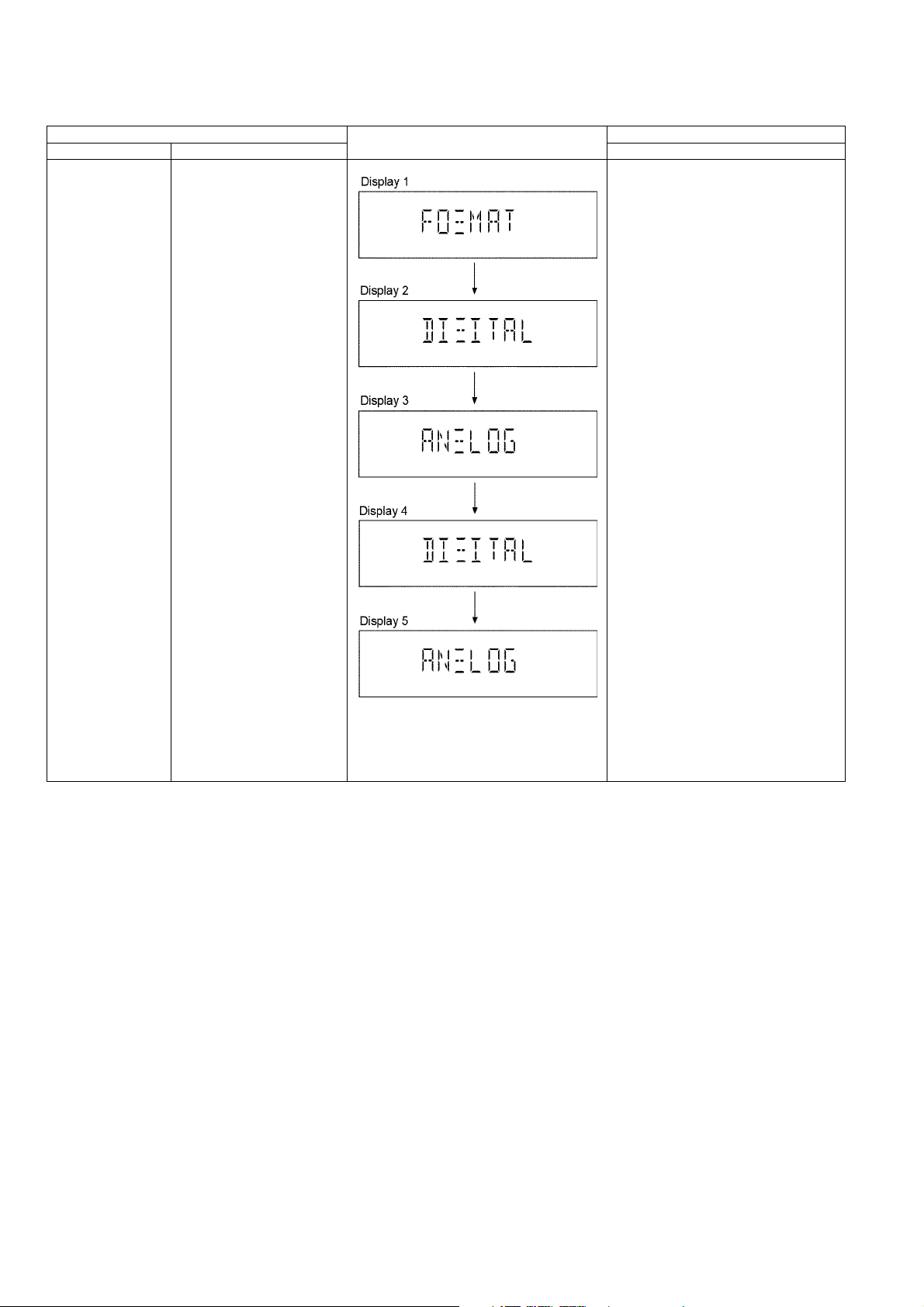
Micro-P Version
Display
To check the firmware
version for Jupiter &
Microprocessor IC.
Display 1
Display 2
In Doctor Mode:
1. Press [2] button on remote control.
17
6.2.2. Doctor Mode Table 2
Item FL Display Key Operation
Mode Name Description Front Key
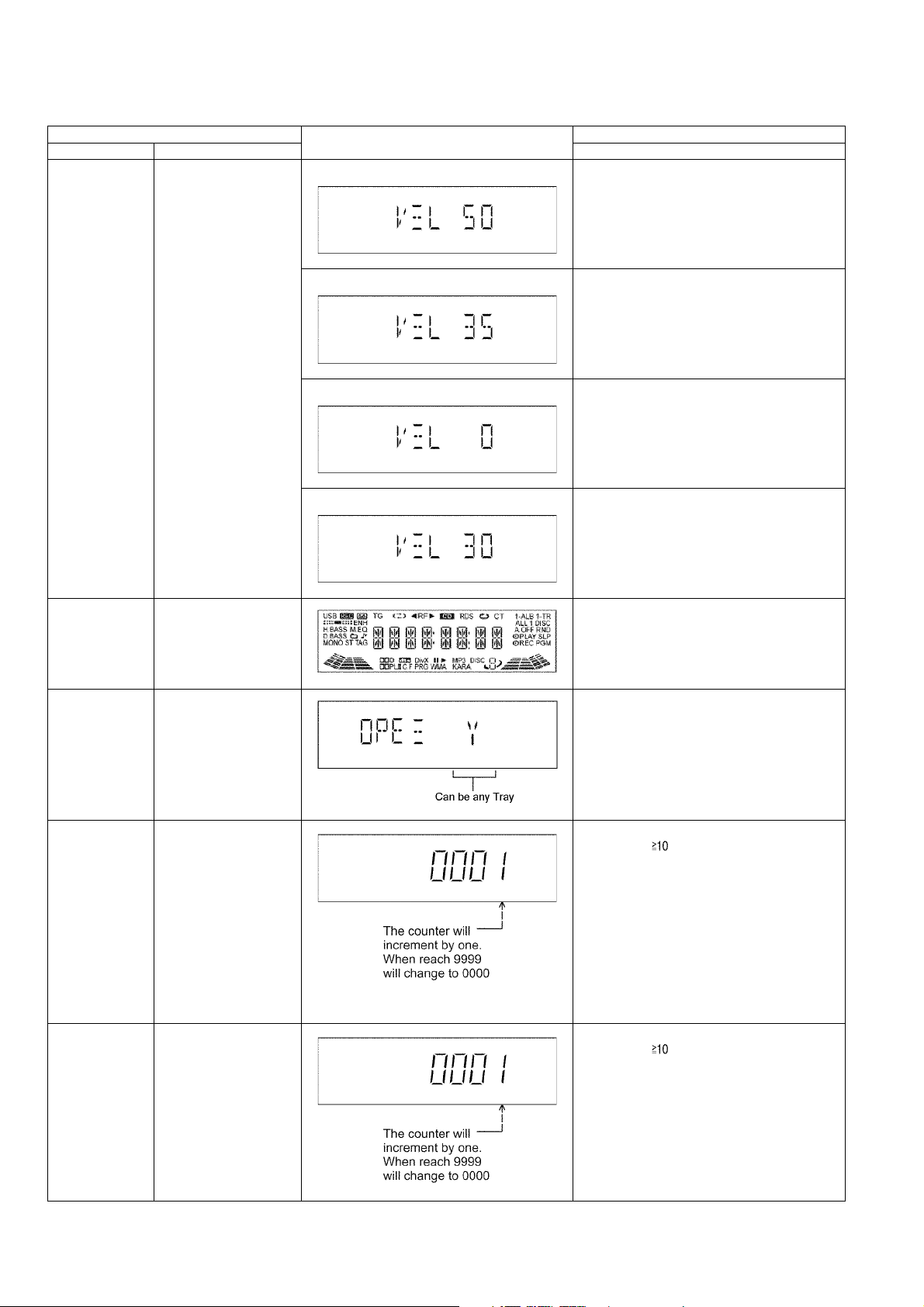
Volume Setting
Check
To check for the volume
setting of the main unit.
The volume will be automatically set to its respective level (in dB). During
this mode, treble/bass/EQ
will be set to ‘0’dB & OFF.
Display 1 In Doctor Mode:
1. Press [7] button on remote control.
To exit Doctor Mode, press [OK] button on main
unit or remote control.
Display 1 In Doctor Mode:
2. Press [8] button on remote control.
To exit Doctor Mode, press [OK] button on main
unit or remote control.
FL Display Check To check the FL
segments display (All
segments will light up)
CD OPEN Test To check the CD OPEN
operation.
CR14 Reliability
Test1 (no retry)
CR14 Reliability
Test2 (with retry)
Note:
1. If the mechanism
error occurs, it
should stop the
test.
(no retry, no recovery process).
2. The test mode is
cleared by power
OFF.
3. Reading and playback should not be
done.
Note:
1. Even if the mechanism error occurs, it
should retry as normal operation.
2. The test mode is
cleared by power
OFF.
3. Reading and playback should not be
done.
Display 1 In Doctor Mode:
3. Press [9] button on remote control.
To exit Doctor Mode, press [OK] button on main
unit or remote control.
Display 1 In Doctor Mode:
4. Press [PLAY MODE/-REPEAT] button on
remote control.
To exit Doctor Mode, press [OK] button on main
unit or remote control.
In Doctor Mode:
1. Press [1] button on remote control.
In Doctor Mode:
1. Press [DEL] button on remote control.
2. Press [OPEN/CLOSE] button on main unit
to close the disc tray.
In Doctor Mode:
1. Press [ ], [1], [1] button on remote control.
In Doctor Mode:
1. Press [ ], [1], [2] button on remote control.
18
6.2.3. Doctor Mode Table 3
Item FL Display Key Operation
Mode Name Description Front Key
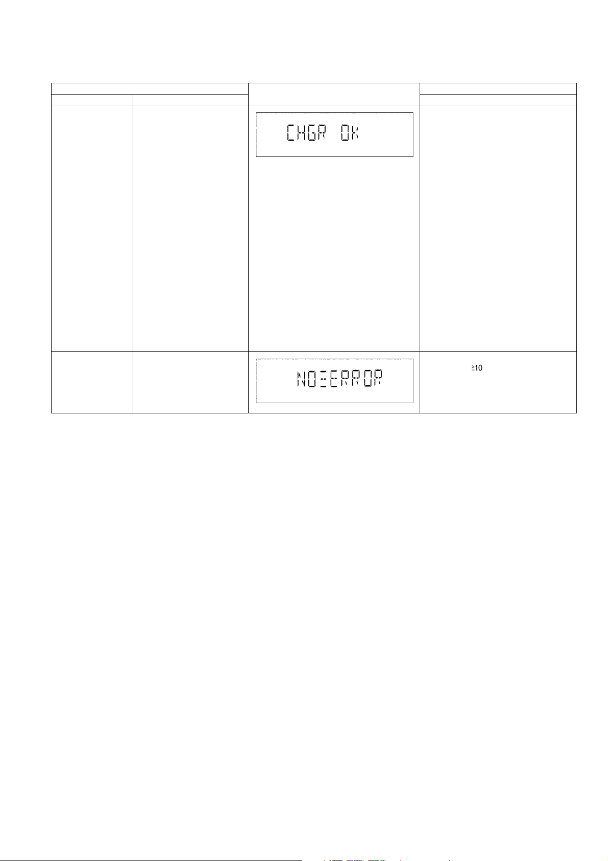
CR14 Inspection Below is the process:
1. Load TRAY 1 (Move to
PLAY position)
2. After that, TRAY 2 is
open (TRAY 1 still in
LOAD condition) and
close.
3. Next TRAY 3 is open
(TRAY 1 still in LOAD
condition) and close.
4. Then TRAY 4 is open
(TRAY 1 still in LOAD
condition) and close.
5. Finally TRAY 5 is open
(TRAY 1 still in LOAD
condition) and close.
6. Tray 1 is unloaded.
(Move to the STOCK
position)
7. Tray 1 is loaded. (Move
to the PLAY position)
When step 1 to 7 operates normally without any error, FL will
display [CHGR_OK_]
CR14 Error Code
Display
To display errors codes for
CR14 changer mechanism.
Refer to section 6.4.1 (CD
Mechanism (CR14) Error code
table).
In Doctor Mode:
1. Press [DISC] button on remote control.
In Doctor Mode:
1. Press [ ], [9], [4] button on
remote control.
19
6.2.4. Doctor Mode Table 4
Item FL Display Key Operation
Mode Name Description Front Key
CD to USB Recording
& Playing Inspection
-Automatically change to CD
-Set it to VOL 0
-Preset EQ Set to FLAT
USB Formatted
When high-speed recording
When analog recording
In Doctor Mode:
1. Press [4] button on remote control.
- Switches to the USB selector
after an analog recording ends
(TRACK 1 of ALBUM1)
During playback this track
- Sets to VOL 50 (0dB) and
start playback
- It is enabled to accept the
SKIP key and the ALBUM key
Next, play the track analog
recorded. (TRACK1 of
ALBUM2)
During playback this track
- It is enabled to accept the
SKIP key and the ALBUM key
20
6.2.5. Doctor Mode Table 5
Item FL Display Key Operation
Mode Name Description Front Key
CD to Memory
Recording & Playing
inspection
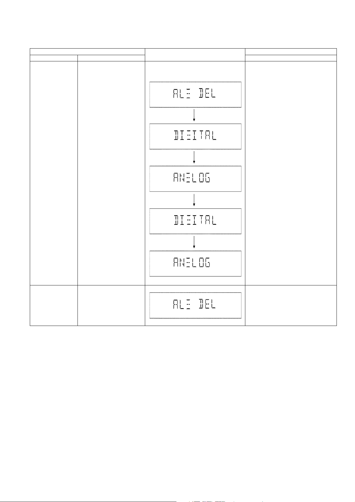
Memory All Delete Change selector to memory
-Automatically change to CD
-Set it to VOL 0
- Preset EQ set to FLAT
Internal Memory Formatted
When high-speed recording
When analog recording
- Switches to the Memory
selector after an analog recording ends (TRACK 1 of
ALBUM1)
During playback this track
- Sets to VOL 50 (0dB) and
start playback
- It is enabled to accept the
SKIP key and the ALBUM key
Next, play the track analog
recorded. (TRACK1 of
ALBUM2)
During playback this track
- It is enabled to accept the
SKIP key and the ALBUM key
and execute ALL DELETE
operation
In Doctor Mode:
1. Press [5] button on remote control.
In Doctor Mode:
1. Press [EDIT MODE] button on
remote control.
21

6.3. Service Mode Summary Table
Main unit buttons Remote control unit buttons Application Note
[]
Service Mode [1] Error Code History
[]
[2] Micro-P Version Display
[5] USB Error Code History
[6] CD Self Adjustment Result (Refer to the section “6.4.2 Service Mode
[3] Cold Start
[8] Memory Error Code History
Service Mode (Refer to the section “6.4.1 Service Mode
Table 1” for more information.)
Table 2” for more information.)
22
6.4. Service Mode Table
6.4.1. Service Mode Table 1
Below is the various special modes for checking:-
Item FL Display Key Operation
Mode Name Description Front Key
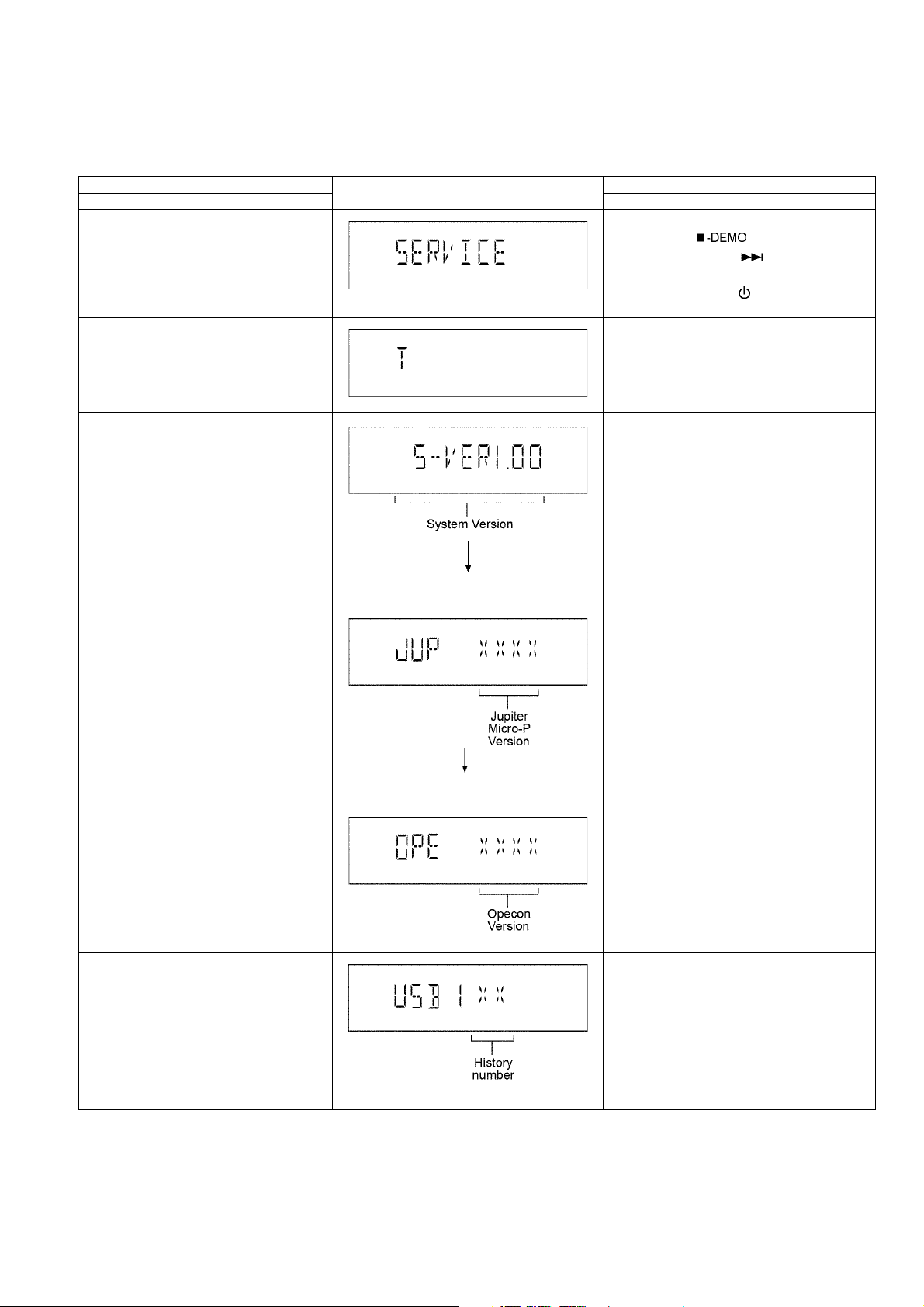
Service Mode To enter into Service
Mode.
Error Code History Checking the records for
Error Code.
In CD Mode:
Press and hold [ ] button on main unit
for 2 seconds follow by [ ] on remote control
for 2 seconds.
To exit, press [ON/OFF ] button on main unit
or remote control.
In Service Mode:
1. Press [1] button on remote control.
To clear history, press & hold [0] for 5 seconds or
more.
Micro-P Version
Display
To Check for following:
1) System Version.
2) Jupiter Micro-processor version.
3) Micro-processor Version
In Service Mode:
1. Press [2] button on remote control.
(Display 1)
(Display 2)
USB Error Code
History
To check for USB error
codes.
In Service Mode:
1. Press [5] button on remote control.
To clear history, press & hold [0] for 5 seconds or
more.
23
6.4.2. Service Mode Table 2
Item FL Display Key Operation
Mode Name Description Front Key
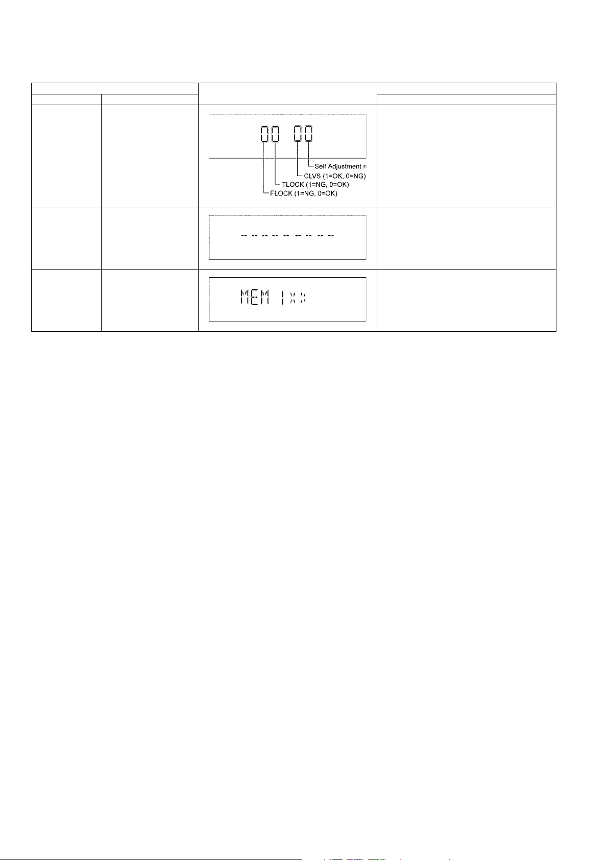
CD Self Adjustment Result
Cold Start To reset to default setting. In Service Mode:
To check for CD operation
(self-adjusment).
In Service Mode:
1. Press [6] button on remote control.
1. Press [3] button on remote control.
Memory Error
Code History
Checking the records for
Error Code.
In Service Mode:
1. Press [8] button on remote control.
24

6.5. Reliability Test Mode (CD Mechanism Unit CR14C)
㪈㩷㫇㫃㪸㫐
㸣
㫌㫅㫃㫆㪸㪻
㸣㸣㸣㸣㸣
㪈㩷㫆㫇㪼㫅 㪈㩷㫆㫇㪼㫅 㪈㩷㫆㫇㪼㫅 㪈㩷㫇㫃㪸㫐 㪈㩷㫆㫇㪼㫅
㸣㸣㸣㸣㸣
㪌㪇㪇㫄㫊㩷㪮㪸㫀㫋 㪌㪇㪇㫄㫊㩷㪮㪸㫀㫋 㪌㪇㪇㫄㫊㩷㪮㪸㫀㫋 㪚㫆㫌㫅㫋㩷㫌㫇 㪌㪇㪇㫄㫊㩷㪮㪸㫀㫋
㸣㸣㸣㸣㸣
㪺㫃㫆㫊㪼 㪺㫃㫆㫊㪼 㪺㫃㫆㫊㪼 㪌㪇㪇㫄㫊㩷㪮㪸㫀㫋 㪺㫃㫆㫊㪼
㸣㸣㸣㸣㸣
㪈㩷㫇㫃㪸㫐 㪈㩷㫇㫃㪸㫐 㪈㩷㫇㫃㪸㫐 㪈㩷㫇㫃㪸㫐㩷㫆㫇㪼㫅 㪈㩷㫇㫃㪸㫐
㸣㸣㸣㸣㸣
㪚㫆㫌㫅㫋㩷㫌㫇 㪚㫆㫌㫅㫋㩷㫌㫇 㪚㫆㫌㫅㫋㩷㫌㫇 㪌㪇㪇㫄㫊㩷㪮㪸㫀㫋 㪚㫆㫌㫅㫋㩷㫌㫇
㸣㸣㸣㸣㸣
㪌㪇㪇㫄㫊㩷㪮㪸㫀㫋 㪌㪇㪇㫄㫊㩷㪮㪸㫀㫋 㪌㪇㪇㫄㫊㩷㪮㪸㫀㫋 㪺㫃㫆㫊㪼 㪌㪇㪇㫄㫊㩷㪮㪸㫀㫋
㸣㸣㸣㸣㸣
㫌㫅㫃㫆㪸㪻 㫌㫅㫃㫆㪸㪻 㫌㫅㫃㫆㪸㪻 㫌㫅㫃㫆㪸㪻 㫌㫅㫃㫆㪸㪻
㸣㸣㸣㸣㸣
㪌㩷㫇㫃㪸㫐 㪌㩷㫇㫃㪸㫐 㪌㩷㫇㫃㪸㫐 㪌㩷㫇㫃㪸㫐 㪌㩷㫇㫃㪸㫐
㸣㸣㸣㸣㸣
㪚㫆㫌㫅㫋㩷㫌㫇 㪚㫆㫌㫅㫋㩷㫌㫇 㪚㫆㫌㫅㫋㩷㫌㫇 㪚㫆㫌㫅㫋㩷㫌㫇 㪚㫆㫌㫅㫋㩷㫌㫇
㸣㸣㸣㸣㸣
㪌㪇㪇㫄㫊㩷㪮㪸㫀㫋 㪌㪇㪇㫄㫊㩷㪮㪸㫀㫋 㪌㪇㪇㫄㫊㩷㪮㪸㫀㫋 㪌㪇㪇㫄㫊㩷㪮㪸㫀㫋 㪌㪇㪇㫄㫊㩷㪮㪸㫀㫋
㸣㸣㸣㸣㸣
㫌㫅㫃㫆㪸㪻 㫌㫅㫃㫆㪸㪻 㫌㫅㫃㫆㪸㪻 㫌㫅㫃㫆㪸㪻 㪌㩷㫇㫃㪸㫐㩷㫆㫇㪼㫅
㸣㸣㸣㸣㸣
㪌㩷㫆㫇㪼㫅 㪌㩷㫆㫇㪼㫅 㪌㩷㫆㫇㪼㫅 㪌㩷㫆㫇㪼㫅 㪌㪇㪇㫄㫊㩷㪮㪸㫀㫋
㸣㸣㸣㸣㸣
㪌㪇㪇㫄㫊㩷㪮㪸㫀㫋 㪌㪇㪇㫄㫊㩷㪮㪸㫀㫋 㪌㪇㪇㫄㫊㩷㪮㪸㫀㫋 㪌㪇㪇㫄㫊㩷㪮㪸㫀㫋 㪺㫃㫆㫊㪼
㸣㸣㸣㸣㸣
㪺㫃㫆㫊㪼 㪺㫃㫆㫊㪼 㪺㫃㫆㫊㪼 㪺㫃㫆㫊㪼 㫌㫅㫃㫆㪸㪻
㸣㸣㸣㸣㸣
㪊㩷㫇㫃㪸㫐 㪊㩷㫆㫇㪼㫅 㪊㩷㫆㫇㪼㫅 㪊㩷㫆㫇㪼㫅 㪊㩷㫆㫇㪼㫅
㸣㸣㸣㸣㸣
㪚㫆㫌㫅㫋㩷㫌㫇 㪌㪇㪇㫄㫊㩷㪮㪸㫀㫋 㪌㪇㪇㫄㫊㩷㪮㪸㫀㫋 㪌㪇㪇㫄㫊㩷㪮㪸㫀㫋 㪌㪇㪇㫄㫊㩷㪮㪸㫀㫋
㸣㸣㸣㸣㸣
㪌㪇㪇㫄㫊㩷㪮㪸㫀㫋 㪺㫃㫆㫊㪼 㪺㫃㫆㫊㪼 㪺㫃㫆㫊㪼 㪺㫃㫆㫊㪼
㸣㸣㸣㸣㸣
㪊㩷㫇㫃㪸㫐㩷㫆㫇㪼㫅 㪊㩷㫇㫃㪸㫐 㪊㩷㫇㫃㪸㫐 㪊㩷㫇㫃㪸㫐 㪊㩷㫇㫃㪸㫐
㸣㸣㸣㸣㸣
㪌㪇㪇㫄㫊㩷㪮㪸㫀㫋 㪚㫆㫌㫅㫋㩷㫌㫇 㪚㫆㫌㫅㫋㩷㫌㫇 㪚㫆㫌㫅㫋㩷㫌㫇 㪚㫆㫌㫅㫋㩷㫌㫇
㸣㸣㸣㸣㸣
㪺㫃㫆㫊㪼 㪌㪇㪇㫄㫊㩷㪮㪸㫀㫋 㪌㪇㪇㫄㫊㩷㪮㪸㫀㫋 㪌㪇㪇㫄㫊㩷㪮㪸㫀㫋 㪌㪇㪇㫄㫊㩷㪮㪸㫀㫋
㸣㸣㸣㸣㸣
㫌㫅㫃㫆㪸㪻 㫌㫅㫃㫆㪸㪻 㫌㫅㫃㫆㪸㪻 㫌㫅㫃㫆㪸㪻 㫌㫅㫃㫆㪸㪻
㸣㸣㸣㸣㸣
㪋㩷㫆㫇㪼㫅 㪋㩷㫇㫃㪸㫐 㪋㩷㫆㫇㪼㫅 㪋㩷㫆㫇㪼㫅 㪋㩷㫆㫇㪼㫅
㸣㸣㸣㸣㸣
㪌㪇㪇㫄㫊㩷㪮㪸㫀㫋 㪚㫆㫌㫅㫋㩷㫌㫇 㪌㪇㪇㫄㫊㩷㪮㪸㫀㫋 㪌㪇㪇㫄㫊㩷㪮㪸㫀㫋 㪌㪇㪇㫄㫊㩷㪮㪸㫀㫋
㸣㸣㸣㸣㸣
㪺㫃㫆㫊㪼 㪌㪇㪇㫄㫊㩷㪮㪸㫀㫋 㪺㫃㫆㫊㪼 㪺㫃㫆㫊㪼 㪺㫃㫆㫊㪼
㸣㸣㸣㸣㸣
㪋㩷㫇㫃㪸㫐 㪋㩷㫇㫃㪸㫐㩷㫆㫇㪼㫅 㪋㩷㫇㫃㪸㫐 㪋㩷㫇㫃㪸㫐 㪋㩷㫇㫃㪸㫐
㸣㸣㸣㸣㸣
㪚㫆㫌㫅㫋㩷㫌㫇 㪌㪇㪇㫄㫊㩷㪮㪸㫀㫋 㪚㫆㫌㫅㫋㩷㫌㫇 㪚㫆㫌㫅㫋㩷㫌㫇 㪚㫆㫌㫅㫋㩷㫌㫇
㸣㸣㸣㸣㸣
㪌㪇㪇㫄㫊㩷㪮㪸㫀㫋 㪺㫃㫆㫊㪼 㪌㪇㪇㫄㫊㩷㪮㪸㫀㫋 㪌㪇㪇㫄㫊㩷㪮㪸㫀㫋 㪌㪇㪇㫄㫊㩷㪮㪸㫀㫋
㸣㸣㸣㸣㸣
㫌㫅㫃㫆㪸㪻 㫌㫅㫃㫆㪸㪻 㫌㫅㫃㫆㪸㪻 㫌㫅㫃㫆㪸㪻 㫌㫅㫃㫆㪸㪻
㸣㸣㸣㸣㸣
㪉㩷㫇㫃㪸㫐 㪉㩷㫇㫃㪸㫐 㪉㩷㫇㫃㪸㫐 㪉㩷㫇㫃㪸㫐 㪉㩷㫇㫃㪸㫐
㸣㸣㸣㸣㸣
㪚㫆㫌㫅㫋㩷㫌㫇 㪚㫆㫌㫅㫋㩷㫌㫇 㪚㫆㫌㫅㫋㩷㫌㫇 㪚㫆㫌㫅㫋㩷㫌㫇 㪚㫆㫌㫅㫋㩷㫌㫇
㸣㸣㸣㸣㸣
㪌㪇㪇㫄㫊㩷㪮㪸㫀㫋 㪌㪇㪇㫄㫊㩷㪮㪸㫀㫋 㪌㪇㪇㫄㫊㩷㪮㪸㫀㫋 㪌㪇㪇㫄㫊㩷㪮㪸㫀㫋 㪌㪇㪇㫄㫊㩷㪮㪸㫀㫋
㸣㸣㸣㸣㸣
㫌㫅㫃㫆㪸㪻 㫌㫅㫃㫆㪸㪻 㪉㩷㫇㫃㪸㫐㩷㫆㫇㪼㫅 㫌㫅㫃㫆㪸㪻 㫌㫅㫃㫆㪸㪻
㸣㸣㸣㸣㸣
㪉㩷㫆㫇㪼㫅 㪉㩷㫆㫇㪼㫅 㪌㪇㪇㫄㫊㩷㪮㪸㫀㫋 㪉㩷㫆㫇㪼㫅 㪉㩷㫆㫇㪼㫅
㸣㸣㸣㸣㸣
㪌㪇㪇㫄㫊㩷㪮㪸㫀㫋 㪌㪇㪇㫄㫊㩷㪮㪸㫀㫋 㪺㫃㫆㫊㪼 㪌㪇㪇㫄㫊㩷㪮㪸㫀㫋 㪌㪇㪇㫄㫊㩷㪮㪸㫀㫋
㸣㸣㸣㸣㸣
㪺㫃㫆㫊㪼 㪺㫃㫆㫊㪼 㫌㫅㫃㫆㪸㪻 㪺㫃㫆㫊㪼 㪺㫃㫆㫊㪼
㸣㸣㸣㸣㸣
Below is the progress flow chart of ageing for the Mechanism unit (CR14C).
25
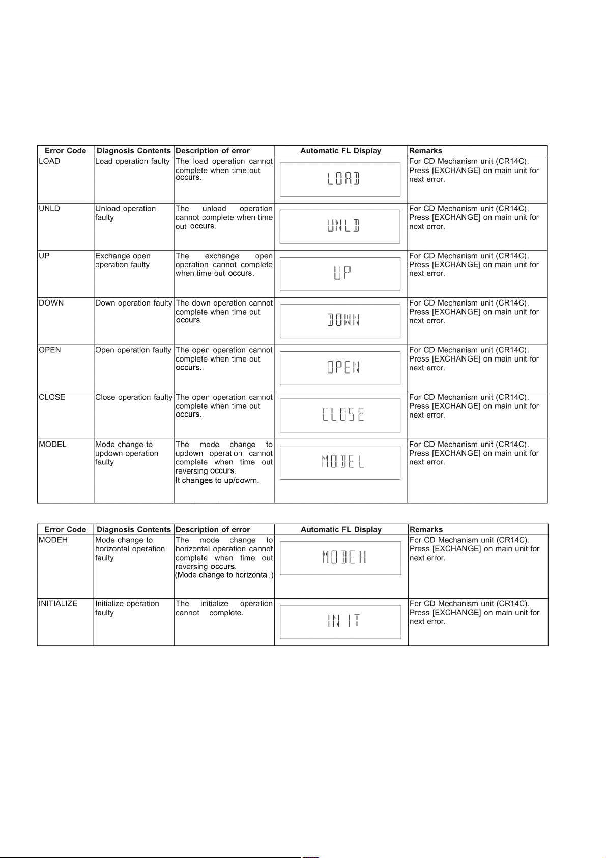
6.6. Error Code Table
Self-Diagnosis Function (refer Section “6.4.1.” Service Mode Table 1”) provides information on any problems occurring for the unit
and its respective components by displaying the error codes. These error code such as U**, H** and F** are stored in memory and
held unless it is cleared.
The error code is automatically display after entering into self-diagnostic mode.
6.6.1. CD Mechanism Unit (CR14C) Error Code Table
26
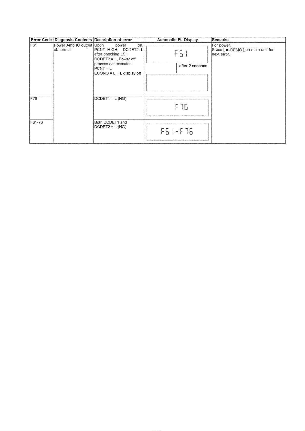
6.6.2. Error Code Table (For Power Supply)
27
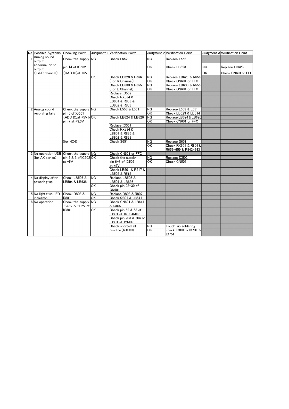
7 Troubleshooting Guide
7.1. Jupiter USB
28
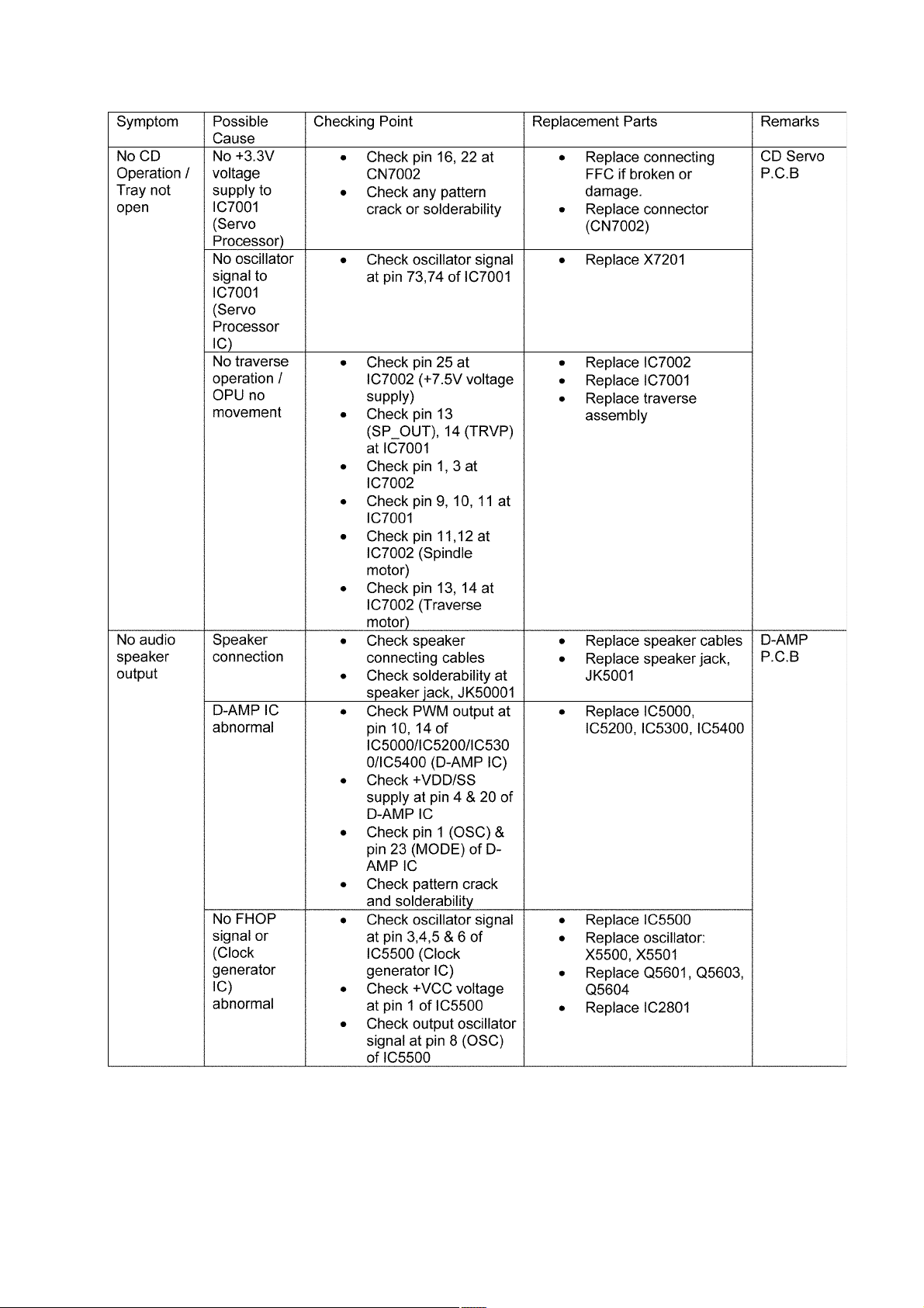
7.2. Troubleshooting Guide
29
30
 Loading...