

Panasonic RS-TR575 Owner’s Manual
Technics
Stereo cassette deck
RS-TR575
Operating Instructions
connecting, operating or adjusting this product, please
these Instructions completely.
Dear Customer
Thank you for purchasing this Technics product.
For optimum performance and safety, please read
these instructions carefully.
The model number and serial number of this product can be
found on either the back or the bottom of the unit.
Please note them in the space provided below and retain
them for future reference.
MODEL NUMBER RS-TR575
SERIAL NUMBER
Before use
Precautions ........................................ 4
Front panel controls .............................. 5
Connections ....................................... 6
Playback
Playback ll_EH_mvJ ............................... 7
Reverse function ....................................... 8
About the automatLc-tape-select function ................ 8
About the remote control function ...................... 8
About the Dolby noise-reduction system ................. 8
About the Dolby HX-Pro headroom extension system ..... 8
Series playback .................................... 9
Linear counter ..................................... 10
To reset the linear counter ............................. 10
To fast-forward or rewind the tape ............. 10
To find the beginning of a program
(TPS function) ...................................... 11
Ill
Recording
Recording .............. i........................... 12
About the ATC function .......................... 14
Series recording ................................... 15
Parallel recordings .............................. .. 16
To make • silent Interval ......................... 17
To make a 4-second silent Interval ...................... 17
To make a silent Interval more than 4 seconds ........... 17
To erase recorded sound ........................ 17
Tape-to-tape recording ........................... 18
To record selected tracks .............................. 19
To out unwanted parts during recording ................. 19
i
Reference
Concerning cassette tapes ...................... 20
Maintenance ....................................... 21
Technical specifications ......................... 21
Troubleshooting guide ........................... 22
Product service .................................... 23
(For USA only)
is subject to the following two conditions: (1) This device may
not cause harmful interference, and (2) this device must ac-
cept any interference received, including interference that
may cause undesired operation.
CAUTION:
This equipment has been tested and found to comply with the
limits for a Class B digital device, pursuant to Part 15 of the
FCC Rules. These limits are designed to provide reasonable
protection against harmful interference in a residential in-
stallation. This equipment generates, uses and can radiate
radio frequency energy and, if not installed and used in accor-
dance with the instructions, may cause harmful interference
to radio communications. However, there is no guarantee that
interference will not occur in a particular installation. If this
equipment does cause harmful interference to radio or televi-
sion reception, which can be determined byturning the equip-
ment off and on, the user is encouraged totry to correct the in-
terference by one of the following measures:
• Reorient or relocate the receiving antenna.
• Increase the separation between the equipment and
receiver.
• Connect the equipment into an outlet on a circuit different
from that to which the receiver is connected.
• Consult the dealer or an experienced radlo/TV technician for
help.
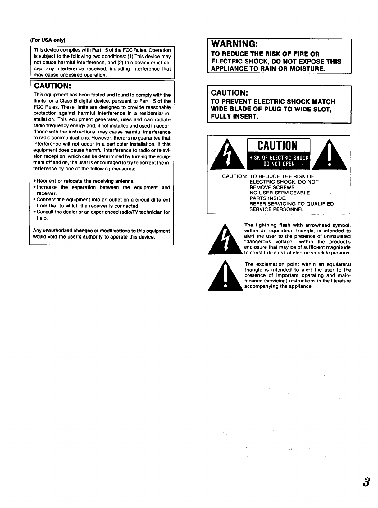
WARNING:
TO REDUCE THE RISK OF FIRE OR
ELECTRIC SHOCK, DO NOT EXPOSE THIS
APPLIANCE TO RAIN OR MOISTURE.
CAUTION:
TO PREVENT ELECTRIC SHOCK MATCH
WIDE BLADE OF PLUG TO WIDE SLOT,
FULLY INSERT.
CAUTION
CAUTION: TO REDUCE THE RISK OF
ELECTRIC SHOCK, DO NOT
REMOVE SCREWS.
NO USER-SERVICEABLE
PARTS INSIDE.
REFER SERVICING TO QUALIFIED
SERVICE PERSONNEL.
Any unauthorized changes or modifications to this equipment
would void the user's authority to operate this device.
within an equilateral triangle, is intended to
alert the user to the presence of uninsulated
"dangerous voltage" within the product's
The lightning flash with arrowhead symbol,
enclosure that may be of sufficient magnitude
to constitute a risk of electric shock to persons.
The exclamation point within an equilateral
triangle is intended to alert the user to the
presence of important operating and main-
tenance (servicing) instructions in the literature.
accompanying the appliance.
3
Before using this unit please read these operating instructions
carefully. Take special care to follow the warnings indicated on
the unit itself as well as the safety suggestions listed below.
Afterwards keep them handy for future reference.
i i
MaJnteBanee (Seepage21.)
Power Source -- The unit should be connected to power sup-
ply only of the type described in the operating instructions or
as marked on the unit.
2. Polarization -- If the unit Is equlpoed with a polarized AC
power plug (a plug having one blade wider than the other),
that plug will tit into the AC outlet only one way. This is a safe-
ty feature. If you are unable to insert the plug fully into the
outlet, try reversing the plug. If the plug should still fail to fit,
contact your electrician to replace your obsolete outlet. Do
not defeat the safety purpose of the polarized plug.
3. Power Cord Protection --AC power supply cords should be
routed so that they are not likely to be walked on or pinched
by Items placed upon or against them. Never take hold of the
plug or cord if your hand is wet, and always grasp the plug
body when connecting or disconnecting it.
4. Nonuse Periods -- When the unit Is not used, turn the power
off. When left unused for a long period of time, the unit should
be unplugged from the household AC outlet.
1. Water and Moisture -- Do not use this unit near water- for ex-
ample, near a bathtub, washbowl, swimming pool, or the like.
Damp basements should also be avoided.
2. Heat -- The unit should be situated away from heat sources
such as radiators and the like. It also should not be placed in
temperatures less than 5°C (41°F) or greater than 35°C
(95 ° F).
Clean the cabinet, panel and controls with a soft cloth lightly
moistened with mild detergent solution.
Do.not use any type of abrasive pad, scouring powder or solvent
such as alcohol or benzine.
Service
1. Damage Requlrin0 Service -- The unit should be serviced by
qualified service personnel when:
(a) The AC power supply cord or the plug has been damaged;
or
(b) Objects have fallen or liquid has been spilled into the unit;
or
(c) The unit has been exposed to rain; or
(d) The unit does not appear to operate normally or exhibits a
marked change in performance; or
(e) The unit has been dropped, or the enclosure damaged.
2. Servicing -- The user should not attempt to service the unit
beyond that described in the operating instructions. All other
servicing should be referred to qualified service personnel.
Placement
1. Ventilation -- The unit should be situated so that its location
or position does not interfere with its proper ventilation. Allow
10 cm (4") clearance from the rear of the unit.
2. Fomi0n Material -- Care should be taken so that objects do
not fall into and liquids are not spilled into the unit. Do not sub-
ject this unit to excessive smoke, dust, mechanical vibration,
or shock.
3. Magnetism -- The unit should be situated away from equip-
ment or devices that generate strong magnetism.
4. Sta©klng -- Do not place heavy objects, other than system
components, on top of the unit.
5. Surface -- Place the unit on a flat, level surface.
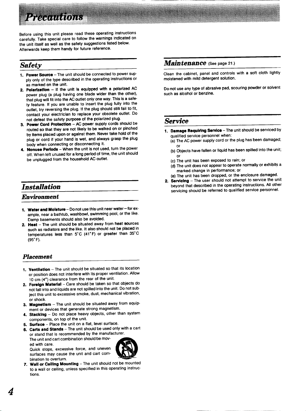
6. Carts and Stands -- The unit should be used only with a cart
or stand that is recommended by the manufacturer.
The unit and cart combination should be mov-
ed with care.
Quick stops, excessive force, and uneven
surfaces may cause the unit and cart com-
bination to overturn.
7. Wall or Ceiling Mounting --The unit should not be mounted
to a wall or ceiling, unless specified in this operating instruc-
tions.
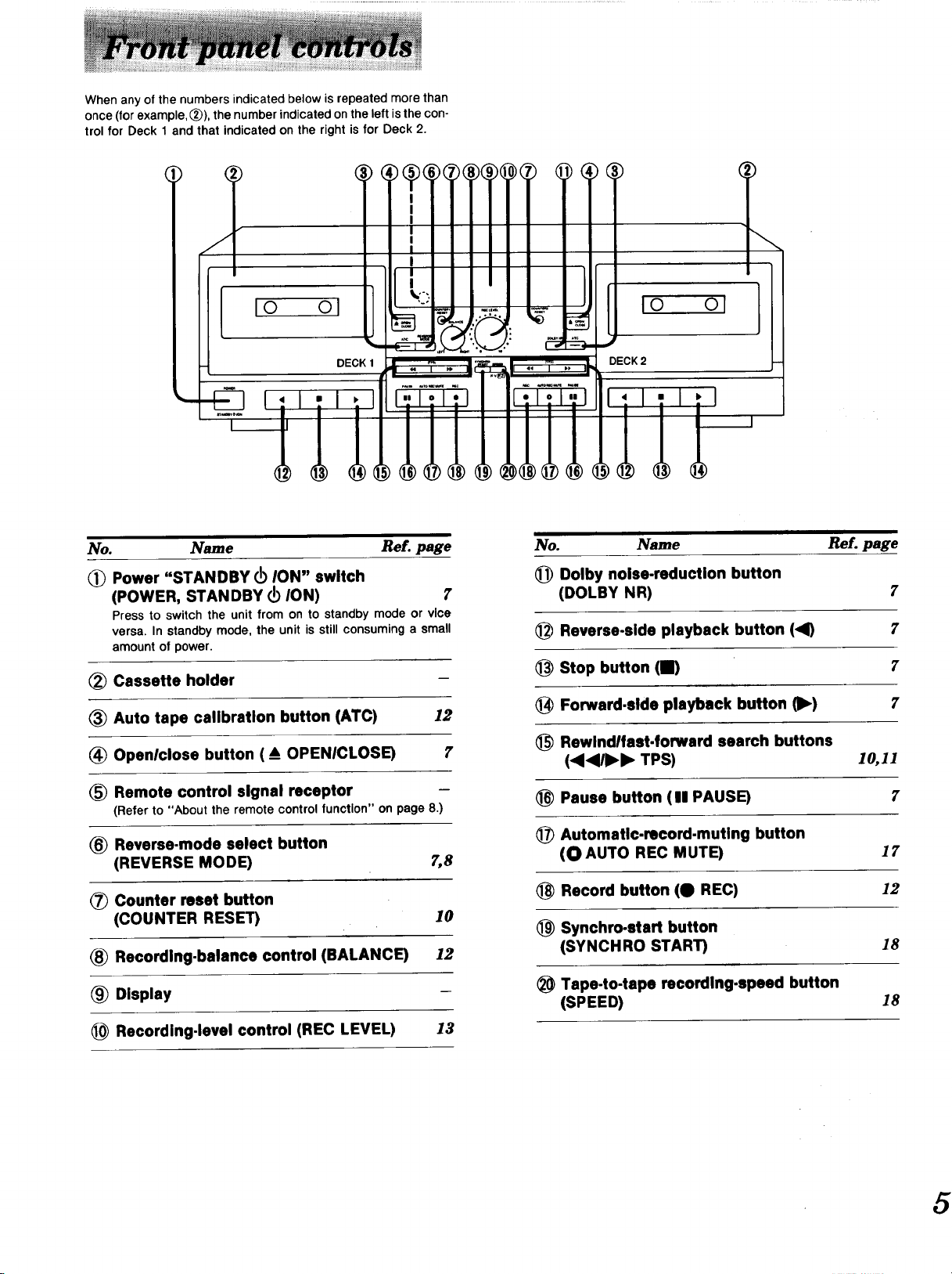
Whenany of the numbers indicated below is repeated more than
once (for example, (_)), the number indicated on the left is the con-
trol for Deck 1 and that indicated on the right is for Deck 2.
IO Ol
No. Name Re£. page
(_ Power "STANDBY OI ION" switch
(POWER, STANDBY OI ION) 7
Press to switch the unit from on to standby mode or vice
versa. In standby mode, the unit is still consuming a small
amount of power.
_) Cassette holder
(_) Auto tape calibration button (ATC) 12
(_) Openlclose button (• OPENICLOSE) 7
I0
DECK2
i ii
el
No. Name Re?. page
(_) Dolby noise-reduction button
(DOLBY NR) 7
(_) Reverse-side playback button (<1) 7
(_ Stop button (Ill) 7
(_ Forward.side playback button 0)_) 7
(_ Rewindlfast-forward search buttons
(4<111_1_ TPS) 10,11
(_ Remote control signal receptor
(Refer to "About the remote control function" on page 8.)
(_ Reverse-mode select button
(REVERSE MODE) 7,8
(_) Counter reset button
(COUNTER RESET) 10
(_ Recording-balance control (BALANCE) /2
Display
Recording-level control (REC LEVEL) 13
(_ Pause button (11 PAUSE) 7
(_) Automatic-record-muting button
(OAUTO REC MUTE) 17
_) Record button (O REC) 12
_) Synchro-start button
(SYNCHRO START) 18
(_ Tape-to-tape recording-speed button
(SPEED) 18

Please check and identify the supplied
accessories
I_IAc power supply ........................ ps.
(For USA: SJA175-A or SJA175-1)
(For Canada: SJA175)
cord
1
Beforemaking connections,makesure thatthepowerto thisunit
and allother systemcomponentsisturnedoff first.
Avoid letting the cables touch each other as much as possible,
otherwisenoise willbe generated.
J Stereo connection cable
White (L) _:) I_
Red (R)
D Stereo connection cables
(SJP2249-6) ............................ 2 pcs.
Placements hints
If this unit isplaced near a receiver or a tuner, a "hum" noise
may be heard during tape playback, recording, or AM recep-
tion of the receiver or the tuner.
If this occurs, leave as much space as possible between the
units, or place them where there is the least amount of
"hum".
Receiver
or amplifier
6
I1Rinl
Household AC outlet
(AC 120 V, 60 Hz)
Connect this cord after
all other cables and
cords are connected.
"AC OUTLET" (UNSWlTCHED)
Power is always available, regardless of the unit's power
switch setting.
Audio equipment rated up to 100 W can be connected.

Either normal, CrO2 or metal type cassettes can be used.
1 524 3
r_mmm d
I ioI ol io ol
I I DE(_K 1 _ -- _ _ IOECK 2 I-
' I -J, I-I
I I '"'" '(_£:;_-'"' "' I ...... '
-E_ I11 ; l!l _ I;F:'i71 I,.1! I ;I I
I I I I I,,.. ----
The proceduresdescribedbeloware an exampleofplaybackon
Deck 1.
...._ ......Pr.,;'powEi_i................
(The unit will switch on.)
_' .... _ ..... Press OPi_N/CLOSEI "and
then Insert the cassette
_ tape.
Press again to close the cassette
holder.
I--_--b'";-_'E.....i,'r.;,;"R_;E.siii=O'o'Eio
_J r-_ Select the appropriate
L_ reverse mode.
U U.UU II I LJ U.UU
=._,-,o -. -. -'1 -' =° " *" ="
I
Each time the button is pressed, the indicator will
change in the order: _ --_(_ --*(_).
t I
,__ : One side only.
(_ : Both sides repeatedly (up to 8 times).
_x_ : Both sides, once only.
(Refer to page 8.)
4• or •• will close the holder and begin the
I When the cassette holder isopen, pressing •, Ib', I
desired function.
I
'1_,.1,:,4,_.....Pr_.ii)oLi;;ii_i_'io'.;l_;ct
the appropriate nolse-reduc.
---_ lion system.
t-i t"/ i-) f3 = F/[3 i-_ n
_-_O --IO -10 -3 IO +2 +4
I_ R I_
UU.UU T..e UU.UU
Each time the button is pressed, the indicators will
change in the order: [] _ [] _ off.
Select the same type as that used for recording.
When playing back a tape which was not recorded us-
ing a Dolby NR system, press so that the indicators
go off.
t I
Pr'" ................
_:._._ (Playback will begin.)
"Kv;' _.,) • : To begin from the forward sde
• : To begin from the reverse side.
/-IU.U -I • UU.ULI
_y _,,_,,,,_,-,,,,_-,,,_,,,,_,.,,-.., .,
I-/1"3 I-) "_ = 1"3I"/ t-) I-1
T R iiiiiiinllUlllnnnnnul inl i>
Illuminates Indicates the side being played.
To play back on Deck 2, In steps 2and 5 above, press the but-
tons ( _ and 5 ) for Deck 2.
To temporarily stop playback
P_USE Press II PAUSE.
The "PLAY" indicator will flash.
Press once again to resume playback.
To stop playback
Press i.
7

Reverse function
The reverse function on this unit has three modes (_, (_,
). Read the descriptions below and select the mode as
desired. (Refer to step 4 on page 7.)
Mode
Onlyone sideofthe tape (eitherthe forward side
or the reverseside) willbe played,and operation
will automaticallystop when playbackhas been
completed.
Both sides of the tape will be played repeatedly
eighttimes, andthen operationwillautomatically
stop.
(Ifplaybackisbegunfrom the reverseside,thefor-
ward sidewill be playedseventimes.)
When there Is • tape In only one of the decks
Both sides of the tape will be played once, and
then operationwill automaticallystop.
(Ifplaybackis begunfrom the reverseside,thefor-
ward sidewill not be played.)
When there Is a tape In each of the decks
The forwardand reversesidesofthe tapein Deck
1 will be played, followed by the forward and
reversesidesof the tape in Deck 2, andafter this
operationIs repeated eight times, operationwill
automaticallystop.
(If playback is begun from Deck 2, the tape in
Deck 1 willbe playedseventimes.)
Tape travel
About the Dolby noise-reduction
system
The Dolbynoise-reductionsystemisdesignedto effectivelyredu-
ce the annoying high-frequency "hissing" noise typical of
cassette tapes. During recording,the system functions to in-
crease the high-frequencysound level,the sound,andthen,dur-
ing playback,that same portionis weakenedto bringit backto
the previouslevel.
Thisunit includestwo typesof Dolby noise-reductionsystems,
the DolbyB NR-typeand C NR-type.
Dolby B.type noise.reduction
Noise is reduced to about one-third.
Use this system when playing back tapes recorded by the Dolby-
B noise-reduction system, such as prerecorded music tapes, etc.
Dolby C-type noise-reduction
Noise isreducedto aboutone-tenth.
Usethissystemforthe recordingandplaybackofsoundsources
that have a widedynamic range and good tone quality,such as
FM broadcastsof live performances,etc., andfor playingback
suchtapes.
About the automatic-tape-select
function
This unit is equipped with the automatic-tape-select feature; it
automatically detects the type of tape being used, and then
makes the suitable adjustments of the bias and equalization ac-
cordingly.
ii
About the remote control function
This cassette deck can be operated by using the remote control
provided with a Technics receiver. (For detailed information,
refer to the operating instructions of the receiver.)
During operation from the remote control, the "R.C," Indicator
will light up.
mm mmRC R.C. nm mm
About the Dolby HX-Pro headroom
extension system
Byfunctioningto Improve the maximum outputlevelof thetape's
high-frequencyrange, thissystem permits recordingswithouta
reduction in the level of the sound source's high-frequency
range. In addition,by usingthe systemin parallelwiththis unit's
noise-reductionsystem,recordingandplaybackwitha greatlyex-
tendeddynamicrangeis possible.
Dolby noise reduction and HX Pro headroom extension
manufacturedunderlicensefrom DolbyLaboratoriesLicens-
ingCorporation.HX Pro originatedby Bang& Olufsen.
"DOLBY", the double-D symbol _ and "HX PRO" are
trademarksof DolbyLaboratoriesLicensing Corporation.
8
/._/__I.L/LI It" = _ L/L/.UL./=,-_--=o -s -Io[ -4 -= o ._ +4 p.
Deck t "R.C." Deck 2 "R.C."
indication indication
 Loading...