

Panasonic RAMSA WR-S208, RAMSA WR-S212, RAMSA WR-S216 Operating Instructions Manual

WR·S216
Panasonic
p;
S
TERE
O MIXING
CONSOLES
WR-S208
WR-S212
WR-S216
Oper
ating
InStructions
Before
operating
this
set.
please
lead
these
mslruchons com
ple
tely
GENERAL
Whether
you're
mixing
sound
for a band,
schoo
l
auditorium,
theater,
AN
pr
oduct
ion
studio,
or
night
club,
RAMSA
audio
mixmg
consoles
can
enhance
the
quality
of
your
mix.
That
's because
the
new
RAMSA
audio
mix
ing
consoles
offer
features
that
are
usually
found
on larger,
more
expensive
conso
les .
The
new
RAMSA
aud io
mixing
consoles
are
avai lable in
three
different
configurations: the
eight-input
WR-
S208,
twelve-input
WR-S212
and
sixteen-input
WR-S216.
But
whatever
size
console
your
application
demands,
all
three
models
offer a variety
of
features
designed
for
optimum
performance
.
CONTENTS
FEATURES
BLOCK DIAGRAM IWA-
S212, WR·S216)
......
15
Overall
.........
.... ... . .
..... ......
... .. ..... ...... ... ..
.......
.... 1
LEVEL
DIAGRAM. ..
................
...........
.... ..
16
Mono Input
Section
....
..........
... ........ . ....... 1
SYSTEM APPLICA
nONS
Stereo
Input
Section
.......
..........
... . . .. .. .. ... . ..... 1
Output
Section
.. . ...... .
.. .........
:2
IMPORTANT NOT
ICE
..... . ..
.. ..
... ...... . 2
WR·
S208
. . ......
.............
17
WR-S212,
WR-S216
........ ........ .
...........
..
18
PLANNI
NG
TA8LE ..........
...
........
.... ...............
............ 19
MAJOR OPERATING
FEATURES
........
. "
.. ..
...
.
3.4
SYSTEM CONFIGURATION IWR ·
S208)
...... ................. .... ..
20
MONO INPUT
SECTION.
.......... ...
..
...... . .. .. . 5
SYSTEM CONFIGURATION
(WR·S212
. WR·
S216)
.............
21
STEREO
INPUT SECTION....... . .
..
.. . ..... ... .. 6
TECHNICAL SPECiFiCATI
ONS
...
..
. ...... . ...
?2
OUTPUT SECTION tWR ·
520B) ...................... ..............
7,8
Input
Specifications.
....... ......
...
.......
.... ........... ... ....... .. .. 23
OUTPUT5ECTION
(WR-5212/5216
l.
....................
..... 9,
10
Output
Speciflcalions
.. . ... ... ... ..... ....
24
REAR
PANEL... ........ ...... ...... ....... ... ... .
....
. ......
.. 11.
12
RACK MOUNTING
IWR·S208
only) ....
.............
.
25
CABLE CONNECTIONS TO IN/OUT CONNECTOR . ... .... ...
13
TYPICAL PERFORMANCE ................ .......
...........
......
.......
26
BLOCK
DIAGRAM
(WR-5208)
...........
............. ..... 14
APPEARANCE
...
............ .. 27.
28

FEATURES
Overall
1, Each
of
the
three
types
of
stereo
mixers
have
two
stereo
input
channels,
which
accept
phono
inputs
and
tape/aux
inputs,
and are
designed
to
be
more
compact
than
ever
before
despite
the
number
of
Inputs
provided,
WR-S208
WR-S212
WR-S216
Mic
x8
x12
x16
Phono
x2
x2
x2
Tape/Aux
x2
x2
x2
The
WR-S208
has
the
same
number
of
inputs
as
a
12-input
mixer.
The
WR-S212
has
the
same
number
of
inputs
as
a
16-input
mixer.
The
WR
-$
216
has
the
same
num
be r of
Inputs
as
a
20-input
mixer.
2.
Separate
microphone
and line
inputs
are
provided,
eliminating
the
need
for
repatchlng,
Both
microphone
and
line
inputs
are
electronically
balanced.
3, The
three
send
circuits
can
be
used
for
effects
and
monitoring,
further
widening
the
range
of
a ppl
icatlons.
Monitor
output:
E
Hect
output:
Send
output:
Pre-fader
level
Post-fade r level
Pre-/post-fader
level
(switchable)
4 _
Stereo
output
circuits
(Sub A and
Bl
and
one
mono
output
(Main)
circuit
are
provided, The
main
out
IS
the
combination
of
Sub
A and
Sub B output
signals.
This
signal can be
derived
pre- or
post-
sub
output
fader,
r-
--~!$JSub
B
A Pre Fader
A
Post
L=~~,e~~>-'W'--.J-!>
-~"-
-
- -
0'
Main
BPost
XJ-------v-
~
mr'
5. A
phantom
power
supply
of + 48 V is
provided
for
condenser
microphones.
6.
Aluminum
diecast
end
panels
insure
mechanical
stability.
7.
The
WR-S208
can
be
mounted
in a
rack,
using
op-
tional
rack
fittings.
- 1 -
8,
The
semi-modular
input
structure
combining
four
channels
together
eases
repair
and
testing.
Mono
Input
Section
1.
Exclusive
microphone
Input
connectors
and
line In-
put
jacks
are
provided,
Microphone/line
input
selection
is
accomplished
With
mechanically-interlocked
pushbutton
switches
.
2.
Three-band
equalizers
are
provided.
Turnover
fre-
quencies
are
10kHz,
400
Hz - 6.3
kHz
(sweepable),
and
100
Hz
for
High,
Mid,
and
Low
respectivr.ly.
High:
Shelving
type
± 1 5 dB
Mid:
Peaking
type
± 1 5 dB
Low
Shelving
type
± 1 5 dB
3.
A peak
Indicator
LED is
provided
for
each
Input
for
monitoring
input
signal
level,
4.
Each
Input
is prOVided
with a solo
switch
for
in-
dividual
monitoring
.
5.
An
insertion
circuit
is
provided
for
connecting
ef-
fects
devices
to
individual
input
channels,
6. Three
send
circuits
are
provided
.
Monitor:
Pre-fader
level
Effect
:
Post-fader
level
Send
:
Stereo
Input
Section
Pre-fader
level/post
fader
level
(selectable)
1. A
microphone
input
connector,
phono
input
jacks,
and
tape/aux
input
Jacks are
provided
so
that
patch
work
is
no
longer
necessary.
2,
Phono
and
tape/aux
input
levels
can be In-
dependently
controlled.
3, The
microphone
input has a separate
on/off
switch.
4. A
Mono/Stereo
selector
s~itch
is
included
on
Stereo
input
channels,
5.
Two-band
stereo
equalizers
are
provided
with
turn-
over
frequencies
of
10kHz
(High)
and
100
Hz
(Low),
High
:
Low
:
Shelving
type ± 15
dB
Shelving
type ± 15
dB
6,
Two
send
Circuits are
provided,
Monitor:
Pre-fade r level
Effect:
Post-fader
level
7. A
monaural
solo
switch
is
provided
for
input
man
itoring.
8.
Peak
indicator
LEOs are prOVided
for
monitoring
in-
put
signal
level.

9.
The
fader
is a
60
m m ca rbo n
type
stereo
fade
r
which
controls
the
Idt
and
right
channels
si m u I
tanec
usl y.
o u -,Jut
Section
1.
12-point
LED
bar-graph
meters
(peak
meters)
display
all
outputs
WR-S208:
Three
12'polnt
LED
bar-graph
meters:
11)
Sub
A/Monitor
12)
Sub
B/Send
(3)
MainlEffect
and
Solo
WR-S212,
WR-S216:
Four
12
::lOlnt LED
bar-graph
met~rs:
(1)
Sub
A/E
Ifect
(2)
Sub
B/Send
(3)
Monitor
(4)
Main
and
Solo
2.
The
solo
indicator '_ED
shows
that
the
solo
level
is
Indicated
on
the 1 2-polnt
LED
bar-graph
meter
.
3.
Two
effect
return
cllcuits
are
provided,
each
with
L1
-erurn
input
level
control
and a pan-pot
control.
IMPORTANT NOTICE
1)
The
mixer
OL.:'.puts are
available
In
a f
ew
seconds
after
turning
on
the
power
switch.
It
takes
approx-
il~lately
5
minutes
for
the
mixers
performance
to
be
Lily
stabilized. C lic
k so u
nds
mig
ht
be
heard
before
it is
fully
warmed
up.
21
When
using
the
input
selector
switch
while
the
phantom
power
is
tur-ed
on,
turn
tile
output
fader
down
to
avoid
any
popping
noise
whl::h
might
damage
the
speakers
or
other
equipment
con-
nected
to
the
mixer.
CAUTION:
.Jo
not
connect
unbalanced
microphones
to
the
r:iixer when
using
phantom
power.
Power
supply
ilnd
"Tl ic
rophone
may
be da M
aged.
3)
The
phantom
power
supply
for
mic
inputs
employs
a
slow
start
system
to
avoid
c::ck
sounds
f~om
be-
Ing
produced.
Allow 1 minute
after
pressing
phan-
tom
power
SWltc;-,
for
voltage
to
stabilize.
4)
When
con'lectlng
and
dlscon'lectlng
a rT';crophone
while
the
p"'antom
power
is
turned
on,
click
sounds
may
be
heard
. Be
sure
to
turn
on
the
phantom
power
aLer
connecting
t-e
microphones
to
the
mixer. When
oisconnecting microphones,
wait at
least
20
sec. after
turning
phantom
power
off
.
4.
Tile
WR-S
212
and WR-S
216
employ
60
mm
car-
bon
faders
for
the
monitor
and
send
outputs.
5.
The
WR-S212
and
WR-S216
are
provided
with
stereo
output
)cks
for
control
room
monitOring.
6.
Solo
level
can
be
adjusted
With
the
solo
control
knob,
and
the
solo
ndlcator
I.ED
is
located
near
the
solo
control
knob
to
confirm
solo
monito'ing.
7.
The
output
circui~
contains a built-in
sunrning
pea k
Indicator
LED,
which
indicates
distortion
when
m~ltiple
inpJ
~
signals
are
mixed.
5) Fa
rinse
rtlon
at
the
in
put
patch
points,
use
a
Y-
shaped
adaptor
cord,
wired
as
tip;
return,
ring; send
and
sleeve; comll'on
on a
114"
TRS
phone
plug.
Ring
(Se
nd)
TIp (Re umi
T
.,5
phOM
plug
TS
phone
plug
- 2 -
6)
All
the
meters
are
calibrated
to
0 VU = + 4
dBm
.
The
solo
meter
indicates
actual
summing
bus
level,
which
is
-10
dBm
.
To
set
signal
to
nominal
level
using
the
solo
meter,
adjust
trim
control
for
meter
reading
of
-14
dB
.

MAJOR OPERATING FEATURES
• Top Panel
WR-S208
Peak
Mete
r
-
Power
Switch
.
Phantom
Power
Swrtch
Carbon
{
Fad~r
Mono I nput
Stereo
Inpu r
Output
Section
SeCTion
52<:110n
• Rear Pane
l
WR-S212
Mono
Input
Section
Stereo
Inpul
SecTion
Peak
Meter
OUTput Sec
lion
and
Connector
Mon
Itor
Output
Connector
and .ConnecTor
1"v1ein
OutpUt
Con-::ctor
and Co
~neclo
r
Connector
- 3 -
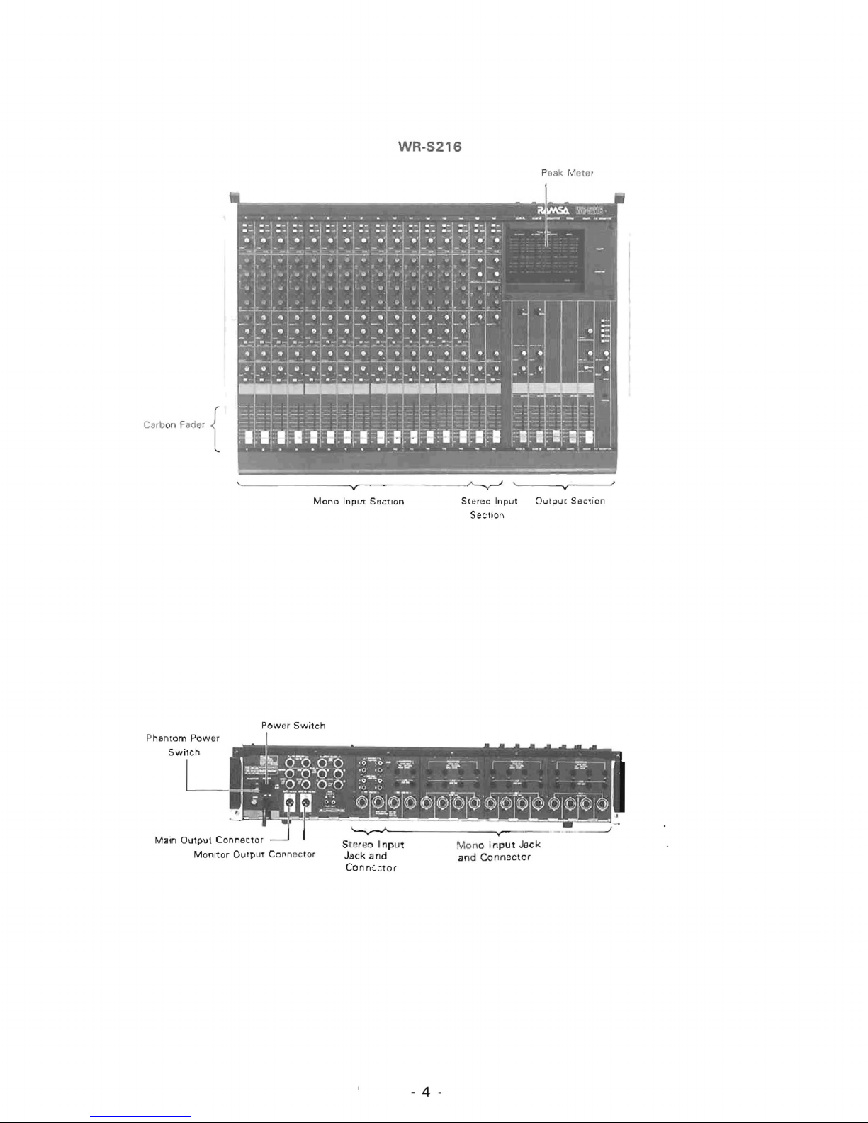
WR-S216
Carb
on
Fader
{
\..
P
eak
Mete
l
~---------------'vr
----------
----~
~
'~----~vr-----J
Mono
InplIt
SBctlon
Pow
er
Switch
Phantom
Pow
er
Main Ou1put
Connector
Monitor
OutpuT
Connector
S
ter
eo
Input
Jack
and
Conn(;:;1or
- 4 -
Stereo
Input
Section
OlJlpU'
Section
Mono Input
Jack
and
Connector

MONO INPUT SECTION
(1)
Input
Selector
Switches
IMicJLine)
These
selector
switches
are used
for
selecting
either
the
microphone
Input
or line i
nput
,
Both
microphone
input
and
line
input
are elec-
tronically
bala
need
,
If
both
the
Mic
and
Line
switches
are
si
multa
neously
pressed, line
Input
is
selected.
12)
Mic/Line
Trim
Control
A
control
to
adjust
the
input
level
of
a
microphone
or
line
input
over a range
of
40
dB:
Trim
at
0
-rim
at
-40
Mic
60
dB
-20
dB
Line
-30
dB
-I-
10
dB
(3)
Peak
level
Indicator
LED
When
the level
of
an Inpt,;t signal reaches a value
6 dB
lower
than
the
maxim
um
output
lev
el,
the
peak
Ind i
cator
LED
w ill lig
ht.
The
peak
level
IS
'Ionitored
at
two
POints,
at
the
preamplifier
and
after
the
equal
izer.
When
this
;"'ED
lights,
the
input
signal
will be
cfstorted,
(4)
Equalizer
Three-band
equalizer: The
high
and
low
bands
are a
shelving
type
with
turnover
frequencies
of
i 0
kHz
and
100
Hz
respectively.
The
mid band
is
a peaking
type
with
a variable frequency range
of
400
Hz -
6.3
kHz.
High: ±·5dB(±12dBatl0kHz)
Shelving
type
1 -C )
Mid
'
±15
dB (400 Hz
to
6.3
kHz)
Peaking
type ( -{}
)
Low:
±15
dB
(±12
dB
at
100
'-1z)
Shelving
type
( > )
(5)
Monitor
Control
This
control
is
used
to
adjust the level sen', to
the
mOI'it
or
bus
line. N.cnit
or
signals are
post-equalizer /pre-f
ader
.
Used
for
foldback
moni
~
Jring
,
(6)
Send
Control
ThiS
control
is
used
to
adJu
s.
the
level
to
the
Send
output.
(7)
Send
Selector
S>_
Jitch
(Pre/Post)
ThiS
switch
selects ei
ther
pre-fader
or
p(;~;t-fader
signals
for
the
Send
output
. Be
cause
Send
out-
put
can
be
sent
at
either
pre-fader
or
post
fader
level,
it
ca"1
be
used
as a
monitor
output
or ef-
fect
output
in a
variety
of
applications.
Pre: Used
for
fold
back
monito
;·i:lg.
P
ost: Used
fo~
eci~:)
and
other
effects.
,
- 5 -
(81
Effect
Control
This is
the
level
control
to the
effect
output, Out-
put
signals
are
post-fader
signals
(9)
Pan
Control
This
knob
is
used
to divid
e
~'le
I
npLt
signal
bet-
ween
stereo
outputs
Sub
A and
Sub
B,
('
0)
Channel
Solo
S\
·
"tch
A
switch
for
monitoring
indiVidual
Input
chan-
nels
through
the
headphones,
Pressing the solo
switch
on the WR-S 21 ? or
WR-S216
causes
the
control
room
man
ITOr
slgn[':1
to
be repl aced
by
the
solo
si(;nE.l.
(11)
Channel
Fader
A
60
mm carbon
fader
to
control
output
level
of input
channels
, Fader
shou
ld
be
at " 0" for
the
rat
Dd
output
level.
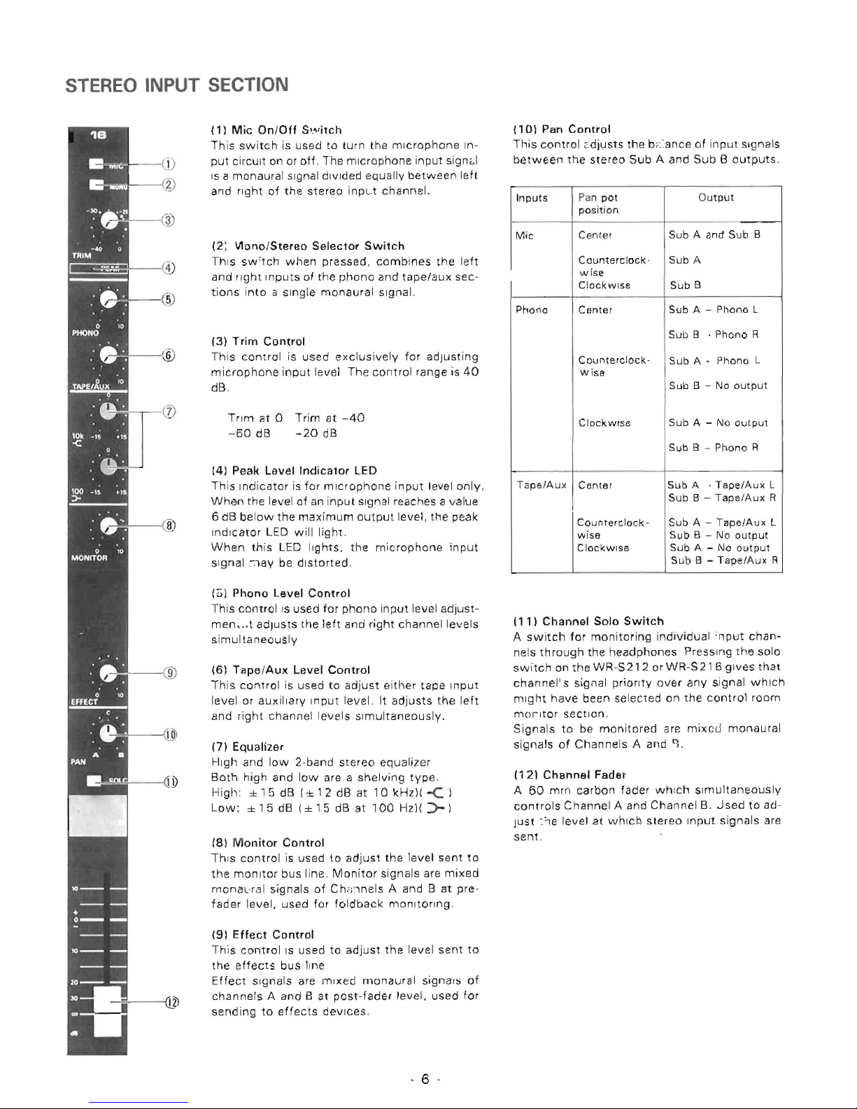
STEREO INPUT SECTION
(11
Mic
On}Off
S'."itch
This
switch
is
used
to
turn
the
microphone
In-
put
circuit
on or
off.
The
microphone
input
signul
IS a monaural
signal
divided
equally
between
lett
and
right
of
the
stereo
i npL.t
channel.
(2; V1onolStereo
Selector
Switch
This sw'
tch
when
pressed,
combines
the
left
and
right
Inputs
01
the
phono
and
tape/aux
sec-
tions
into
a Single
monaural
signal.
(3]
Trim
Control
This
control
is
used
exclusively
for
adjusting
microphone
input
level
The
control
range
is
40
dB.
Trim
at 0 Trim
Elt
-40
-60
dB
-20
dB
(4)
Peak
Level
Indicator
LED
This
Indicator
is
for
microphone
input
level
only.
When
the level
of
an
input
signal reaches a value
6 dB
below
the
maximum
output
level, the
peak
Indicator
LED
will
ligh1.
When
this
LED
Ilg
hts.
the
mic
rophone
in
put
Signal
~18y
be
distorted.
(~1
Phona
Level
Control
This
control
IS
used
for
phono
input
level
adjust-
men •.. t adJusts
the
left
and
right
channel
levels
simultaneously
(6)
TapelAux
Level
Control
This
control
is
used
to
adjust
either
tape
Input
level
or
auxiliary
I n
put
level. It
adjusts
the
left
and
right
channel
levels
Simultaneously.
(7)
Equalizer
High
and
low
2·band
stereo
equali
zer
Both
high
and
low
are a
shelving
type
.
High
: ± 1 5 dB I ± 1 2 dB
at
10
kHz)(
-C
)
Low:
± 1 5 dB I ± 1 5 dB
at
100
Hz)(
::>-
I
18)
M
onitor
Control
Th
is
control
is
used
to
adjust
the
level
sent
to
the
monitor
bus line. Monitor
signals
are
mixed
monaL
·ral
signals
of
Ch;
nnels
A and B
at
pre -
fad
er
level,
used
for
foldback
monitoring
.
(9)
Effect
Control
This
control
IS
used
to
adjust
the
level
sent
to
the
effects
bus
line
E
Ifect
Signals are
mixed
monaura I signa,s
of
channels A and B at
post-fader
level,
used
for
send
ing
to
effects
devices
.
. 6 -
(101 Pan
Control
This
control 2.djusts
the
bi::ance
of
in
put
signals
between
the
stereo
Sub A and
Sub 8 outputs
.
Inputs
Pan
pot
O
utput
pos
iti
on
Mic
Center
Sub A and
Sub
B
Counterclock
·
Sub
A
wise
ClockWise
Sub
B
Phono
Center
Sub A -
Phono
L
Sub
B
.
Phono
R
Counterclock-
Sub A -
Phono
L
wisa
Sub B -
No
OUtput
ClockWise
Sub
A -
No
oUlput
Sub B -
Phono
R
Taps/Aux
Centsr
Sub
A
.
Tape/Aux
L
Sub
B -
Tape/Aux
R
C
oun
tere
lock-Sub
A -
Tape/Aux
L
wise
Sub
B -
No
output
ClockWise
Sub
A -
No
output
Sub
B -
Tape/Aux
R
(11)
Channel
Solo
Switch
A
switch
for
monitoring
individual ;nput
chan-
nels
th
rough
the
headphones
PresSing
the
solo
switch
on
the
WR-S
212
or
WR-S21 6 gives
that
channel's
signal
priority
over
any
signal
which
might
have
been
select
ed
on
the
control
room
mor
Itor
section
.
Signals
to
be
monitored a ra
mixed
monau
ral
signals
of
Channels
A and
'1
.
(121
Channel
Fader
A
60
mrn
carbon
fader
which
Simultaneously
controls
Channel
A and
Channel
B.
Jsed
to
ad-
Just :
'le
level
at
whlci:1
stereo
Input
signals
are
sent
,
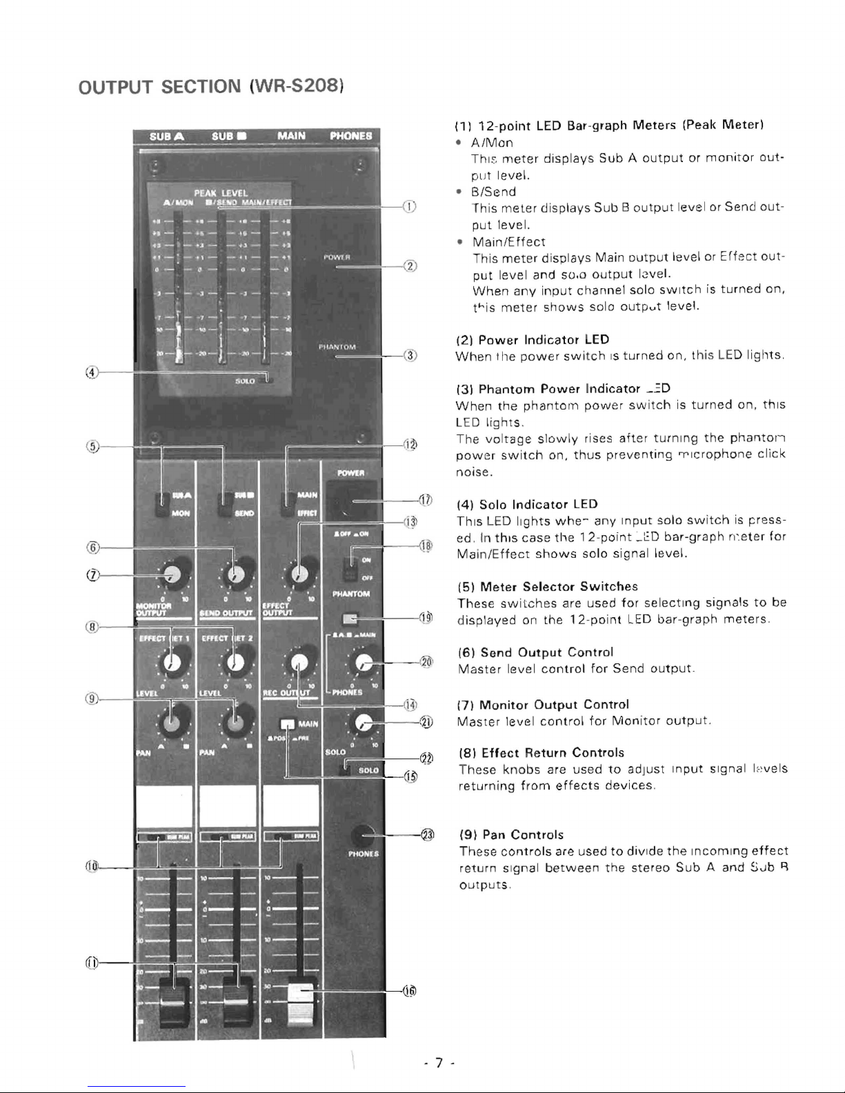
OUTPUT SECTION (WR-S208)
(1)
•
A/Man
Thl."
PLJ
•
B/Send
12-point
t
LED Bar-
meter
level.
This meter di
put
level.
•
Main/Effect
This mete
pu t l
When
this
(2)
Power
When the
(3)
Phantom
When
LED ligh t s.
r disp lays
eve I and
any
input
meter
Indicator
power
Power Indicator
the
phantom power swi
The voltage slo
power
noise
switch on,
.
displays
splays
so .o
channel
shows
switch
wly
thus
graph
Meters
Sub
A ou
Sub
B o
utput
Main outp
output 18vel.
solo
solo
outp
LED
IS
turned on,
_~D
rises
after
preventing
(Peak
tput
or
monitor
level
or
ut
level
or Ef
sWitch
is
turned
.... t level.
thi
s LED
tch
is
turn
ed
turning
the
'T'lcrophone click
Meter)
Send
fect out-
lights
on, this
phantol
out-
out-
on,
.
i
(4)
Solo
Indicator
This LED
ed
. In
this
Main/Ef
(5)
fect
Meter
These swit
di
splayed
Send
(6)
Ma
ster
level
Monitor
(7)
Mas
ter
level control for
(8)
Effect
T
hese knobs
retu
rning
(9)
Pan
Controls
Th
ese
controls
return Si
outputs.
LED
lights
whe-
any
case
the 12-
shows
Selector
ches
on
the
Output
control
Output
solo
Switches
are
used
12-point
Control
for
Control
point
signal level.
Send
Monitor
Return
from
Controls
are
effects
are
used
used
to
devices
to
gnal between the
Input
_~D
for
LED
adjust
divide
stereo
solo
swit
bar-graph
selecting
bar-graph
output
output.
Input
.
the
Sub A
ch
is
n~et e
signals
mete
.
Signal
Incoming
and
p ess-
r
for
to
be
rs.
I:· ~
vels
effect
S-.Jb
~
- 7 -
Input
Pan
pot
position
Output
Effect
Center
Sub A and
Sub
8
Return
1
Counterclock-
Sub A
w ise
Clockwise
Sub
B
Effect
Center
Sub A and Sub 8
Return
2
Counter
clock
- Sub A
wise
Clockwise
Sub B
(10
1
Sum
Peak
Indicator
LEOs
These LEDs
light
at
+
14
dB,
whi
ch is 6
dB
down
from
the
summing
point
pre-fader
clipping level
(+
20
dB)_
When
this LIED
lights, output
signals
will
be
distorted
.
In
this
case,
lower
all
input
faders
so
{hat
LED
does
not
light
.
(11)
Sub
A/Sub B Output
Faders
60
mm
carbon
faders,
used
to
adjust
Sub A Elnd
Sub
B
output
levels. Position 0 represents
the
rated
out-
put
level.
(12)
Meter
Selector
Switch
This
switch
selects
either
the
Main
or
Effect
signal
to
be
displayed
on
its
respective
bar-graph
meter
.
When
any
solo
switch
IS
on,
the
meter
displays
solo
level
regardless
of
the
SWitch
pOSition.
(13)
Effect
Output
Control
Master
level
control
for
Effect
output
.
(14)
Record
Output
Control
Record
output
level
adjusting
knob. Channel A and
Channel
8 are
simultaneously
adjusted
.
Sub A and
Sub B pre-fader
level
signals
feed
this
control.
(15)
Main
Output
Pre/Post
Selector
Switch
This
switch
sets
the
Main
output
to
the
pre-fader
level
or
post-fader
level
of
Sub A and
Sub
B.
Pressing
the
switch
down
sets
Main
output
to
pre-
fader
level,
and
pressing
It
again
to
the
up
position
returns
Main
output
to
post-fader
level.
Pre:
Ma
in
output
signal IS
derived
pre -
Sub
A/Sub B faders. This
mode
allows
separate
stereo
and
mono
mixes
si
multaneously.
Post
:
Main
output
signal
is deri
ved
post-
Sub
A/Sub B faders.
This
is
useful
for
sub
grouping
of
inputs
.
Note:
In
"Post"
position
Sub A and
Sub B faders must be
raised for
output
signal
to
be
present
at
Main
output
.
- 8 -
(16)
Main
Output
Fader
A
60
mm
carbon
fader
for
adjusting
Main
output
level.
Position 0 represents
the
rated
output
level.
The
Ma
in
output
signal
is a
summed
monaural
signal
from
Sub
A
and
Sub
B
(17)
Power
Switch
When
this
switch
is
pressed,
mixer
power
IS
turned
on and
the
power
indicator
LED
lights.
A
muting
circuit
is
provided
for
protecting
the
devices
connected
to
the
output
from
click
noise.
The
unit
is
ready
for
operation
about 5 or 6 seconds
after
swit-
ching
power on.
(18)
Phantom
Power
Switch
This
power
switch
is
for
condenser
microphones,
and
turns
0 C
48 V on
and
off.
Be sure
to
use a
balanced
type
condenser
microphone
because
DC I 48
V is
applied
to
pin 2 (hot)
and
pin
3
(cold)
of
the
microphone
connector
and DC 0 V
to
pin 1 (Common)
.
Turn
all
output
faders
to
the
minimum
position
to
pre-
vent
click
noise
before
turning
the
phantom
power
switch
on
or
off.
Note:
The
power swit
ch
(17)
and
phantom
power swi
tch
(18)
on
the
WR-S
208
are
located
on
the
operation
panel
because
the
WR-S208
may
be
mounted
in a
rack.
When
connect
ing a
microphone
to
the
microphone
connector, make
sure
that
phantom
power
is
off
.
(19)
Headphone
Selector
Switch
This
switch
is
used
for
select
ing
signals
to
be
monitored
with
the
headphones
.
When
this
switch
is
pushed
down,
Main
output
can
be
monitored
monaurally. When
the
switch
is
push-
ed
again
to
the
up
position,
Sub A and
Sub B outputs
can be
monitored
in
stereo.
(20)
Phones
Control
Th
is
knob
is
used
for
adjusting
headphone
monitor
level.
Sub A and
Sub B signals
are
simultaneously
adjusted.
(21)
Solo
Control
This
control
adjusts
the
level
of
the
solo
signal
present
at
the
headphone
output.
(22)
Solo
Indicator
LED
This
LED
tights
if
anyone
of
the
input
solo
switches
is
on.
(23)
Phones
1/4"
TRS
phone
jack
for
headphones
.
Maximum
output
is 1.2 W +
1.2
W/8
ohms.
 Loading...