

Panasonic RAMSA WP-9055 Operating Instructions Manual

Panason
ic~
2-channel
power
amplifier
50W
(RMS)
+ 50W (RMS)/B ohms
WP-9055
Operating
Instructions
Befo
r,:
attemp:
I
()g
10 use I e produc(,
pl
ease
read
these
Ifl
S1r
ucl
,o s
com
pletely
FEATURES
• This
unit
is
compuct
and
will
fit
into
a single rack
space
.
• The
WP-9055
in 2-channel power
amplifier
prOVIding
continuous
outputs
of
50 W (RMS) + 50 W (RMS)
(THO
0.05% or l
ess for
8D. load 20
Hz
to
20
kHz)
employing electronic balanced
input
c:r,~ults.
• In bridge mono mode, the power
amplifier
prOVIdes
a
100
W (RMS)
outpu. (THO
005%
or
less
, for :6D.load
20 Hz
to
20
kHz)'
• The
inpul
circuit
IS
electronically balanced
employin
g
an
operaTIonal ampl
iii
er
of
exce'lent irClnsien r response
and
Wide
bandWidTh. As a result,
deterioration
of
response caused
by
the transformer and the
effect
of
induction
'Wise ;j
re
minimized
•
Two
tyPflS
of
input
connectors are provided on each
(I,annel : X
til-type
connectors (female) and
1/4"
TRS
phone jacks
•
Output
level
can
be
mon
itored
by
LEn's
.
• Remote
monitor
outrl:ts
are
prOVided
on
each
channel.
These include VL, meter
outputs
and external
access
10
relay contacts allowing cOf)',lIlete
indication
of
operating
status
of
amplifier
• The
amplifier
is
protected
by
a
VI-type
energy
limiter
(voltage/current sensing
protection
Circuit)
that
limits
the power supply in
the
evei'll
of a short
circuit
and cuts
off the
output
in the eve
nt
01
overheating or mal·
function.
READ THE FOLLOWING
INSTRUCTIONS
BEFORE USE
• This uni ( sho Id
ve inst
alled on a rig id,
at
sur a
ce
or
secured
in a rae
.
• Do at Instal t"e
unit with the rear
Side
lachfj
down
.
• Do
not
put any obiect on
lop
of
the
unl"
• Due to the IohJling circuit
Iflcorpo
ra
ed, no sound is
produced for 4 D 6
seconds
attr., turning on the power
supp y
•
Alwa'ls use ~ ::lower source
of
adequa
,2
capaCITY
• Do
not
turn
on
the
pow
er
of mult
iple power ampl ifiers
a t the same t i
rr e Nev
er
allow the ventil ai 'on
ho les on
the
top
and
bottom
of
the ampl i fier to get
obstruct
ed
in any way .
,
T~~.s
unit
is
self-cooled. Always
be
su
re
there
is
adequate
ventilation
In
instal lation.
Nev
er
block
the vent holes on
the
top
and
bottom.
•
To
clean the
amplifier,
wipe It With a
dry
cloth
.
If
the
ca
se is very
dirty,
wipe
it
wi
h a
ClOth
dampen
ed
i.
wat
e or
mild
soapy water, hen
\IV
ipe
dry
thor
ough 1
'1.
Never
use solvents or chern ical
cloth
; Sllll, 'urly, never
spray
1$,·(tlcldes
as
they I lay cause disc
oloration
or
peeling.
• I
i any
trou
ble
IS
fou nd, disconnect
'(h-:
POWEl-
cord and
cont
act
your dealer.
WARNING:
TO
PREVENT
FIRE
OR SHOCK
HAZARD,
DO
NOT
EXPOSE
THIS
APPLIANCE TO
RAIN
OR
MOISTURE,
MAJOR
OPERATING CONTROLS
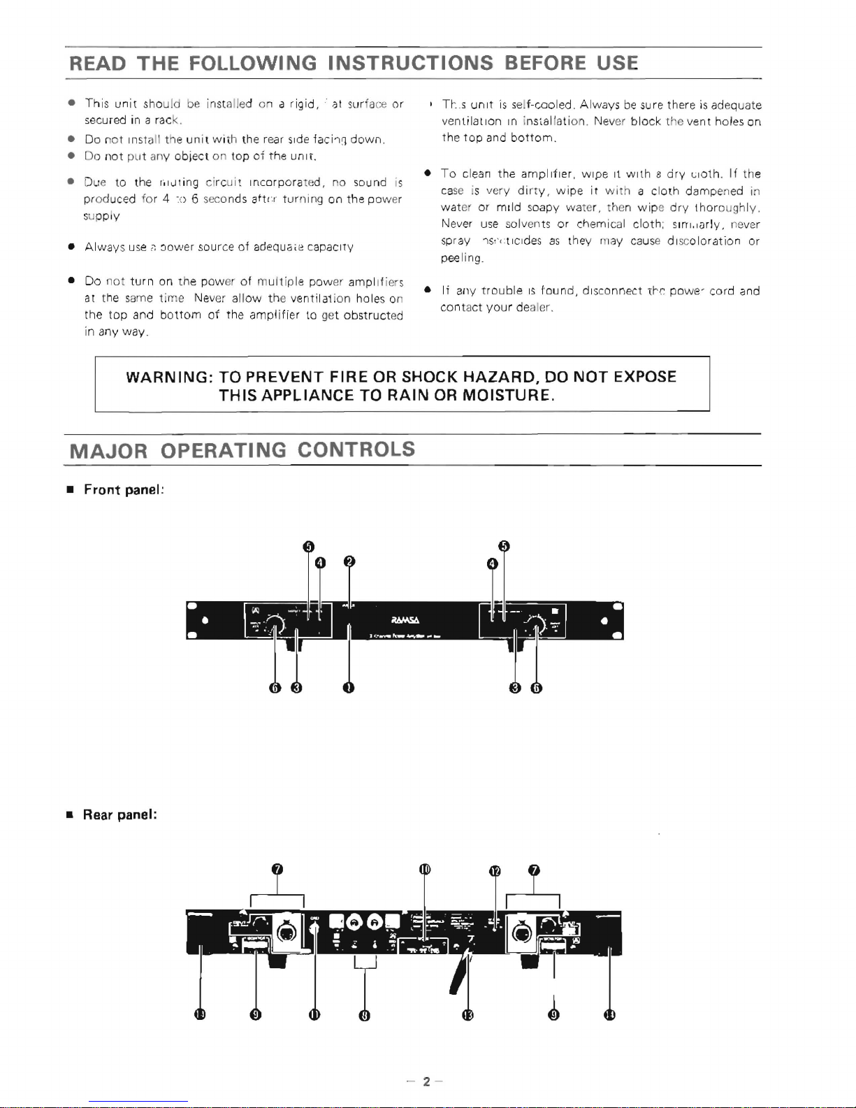
• Front panel:
--.
.
~
j~~.";;";".
J
r~
.
....
rw.
......
__
...
_ • •
• Rear panel:
- 2 -
o Power switch [POWER)
• The power
ampll'
!r
reaches the operating conditions
with
in 4 to 6 seco
nds after lu rn I
ng
on th e Power
switch, due to a rnutlf,g eireu
it
wh ich prevents
switch-
in
g noise al powe r-up,
CAUTION:
When using the WP-9055 in a system
with
other
equipment such
as
a mixer, equalizer, crossover,
etc"
always
turn
the
amplifier
on last
as
switching
noise
from
the
other
equ
ipment can damage the
speakers.
Sim
ilarly,
at system power-down always
tu
rn the
amplifier
off
first.
8 Power ON indicator lamp {POWER] (red)
Indicates that the
amplifier
is
turned
on.
o Protect indicator lamp
[PROTECT]
(red)
This
'EO
indicates
thai
the
mutmg
circuit
IS
activated
and
trerefore
sound cannot
be
produced at the
output
This occurs
for
4 10 6
~cconds
when the ampl
ifier
IS
turned on, and also during overheating or any malfunction
that
may
cause
dll:nage to th e speakers.
o
Peak
level indicator lamp
[PEAK
(red)
CAl
,
(ID
1
Sound
is
distorted as soon
as
PEAK
lamp (red) lights.
Shou
Id
thiS occur,
el
ther adjust t
he
output
level
of
the
mixer
or
adjust the power amplif ier
Input
Level
control
so
that
the PEAK
LED turns
off
.
" Signal level indicator lamp
[SIGNAL
(green)
IKI
, [[I]
Ugh
IS when the sign
al
level
reaches -20
dB below the
rated
output
level.
o
Input
level
control
[INPUT
ATT
@,
~)
• When this control
is
at "0'" the
amplifier
Will reach
iTS
rated power
output
when
the
input
signal
is
at
a level
OL
+ 4 dB.
• The calibrated markings
on
the
~rom
panel indicate
the
amount
of
attenuation
applied
to
the
input
signal
in 1 dB
steps up
to
- 19
dB
This allows proper
volu 'ne setting
of
the speakers when the
input
signal
source's
at its rated
output
level.
•
No
sound
is
produced when
the;
control
is
ir' the
"
00
"position
o I
nput
connectors [I NPUT
@,
lID]
• +4 dB
40
kn
8a"lnced.
•
The Input conllc;ctors are
of
two
different
types
3-p
in
X L A-type G'lr'nectors
(~emale)
and
1/4"
tip-
ring-sleeve phone
Jacks.
• These inp
ut
connectors
are
CO'lnecTed
In
parall
el
mtsrnally
. Do
not
connect more than one
input
signal
to
these connectors at
the
same
time,
• When using am
plifier
in bridge-mono mode, connect
the
Input signal
TO
~
channel
only
Any
signal
connected
to
[ffi channel
will
(lot
be
::,assed.
-3-
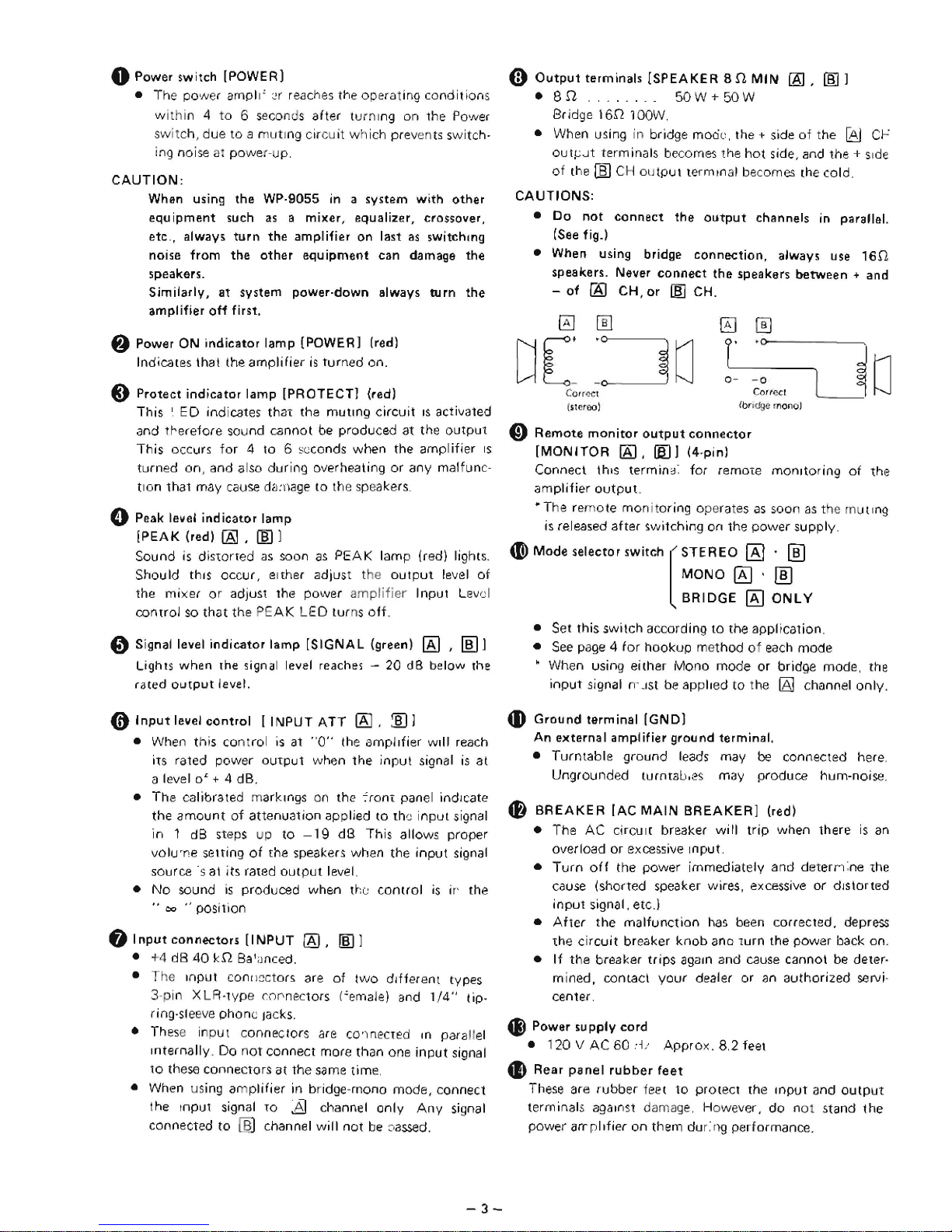
(i)
Output
terminals [SPEAKER
8.11
MIN
(8],
lID]
.8.11
50W+50W
Bridge
16.11
lOOW,
• When using in bridge mocil', the + side
of
the
[Aj
Cr-:
oul~.Jt
terminals becomes the
hot
side, and the +
Side
of
the I]) CH ou
tput
terminal becomes the cold,
CAUTIONS:
•
Do
not
connect the
output
channels in parallel.
(See
fig_)
• When using bridge connection, always
use
16.11
speakers. Never connect
the
speakers between + and
-
of
[AI
CH, or
1m
CH.
0
[[1
0
0
DE
:
:~O
r-
-0
0-
-0
C
or(l.~ct
Corf~CI
(stcr
00
I
(bri
dge
monol
o Remote
monitor
output
connector
[MONnOR
[AJ,
lID
J (4-pinl
LJo
Connect
thiS
termind:
for
remOTe
monitoring
of
the
amplifier
output.
• The rem
ote
monitoring operates
as
soon
as
t 18 mu t
Ing
is
released after switching on the
power
supply.
(I) Mode selector
~witch
[STEREO
gj -[[]
MONO
~
.
lID
BRIDGE
IKI
ONLY
• Set this switch according
to
the appl ication.
•
See
page 4 for
hookup method
of
each
mode
• When using either
Mono
mode or bridge mode, the
input
si
gna
I n'
-1st
be
app lied
to
the
IAJ
channel
on
Iy.
4D
Ground terminal
[GND]
An externa I ampl
ifier
grou nd terminal.
•
Turntable
ground leads may be connected here,
Ungrounded turntab,es may produce hum-noise.
f)
BREAKER
[AC
MAIN
BREAKER]
(red)
• The AC circu I [ breaker wi
II
trip
when there
is
an
overload or excessive Input.
•
Turn
off
the power immediately and
deterrl
:ne
,he
cause (shorted speaker wires, excessive or
distorted
input
signal. etc.)
•
After
the
malfunction
has
been corrected, depress
the
circuit
breaker
knob
anD
Turn the power back on.
•
If
the
breaker trips
agam
and cause cannot
be
deter-
mined,
contact
your
dealer or
an
authorized servi-
center,
4i)
Power 5upply cord
•
120
V AC
60
:1/
Approx.
8,2 feet
..
Rear
panel
rubber
feet
These are
rubber
feet
to
protect the
Input
and
output
term inals against dama
ge,
However,
do
n01 stand
the
power
arrpllfier
on
them dur:ng performance.
 Loading...