

Page 1

HO Oigital Receiver
QTRSn40
Operat^ing inst;ruGt;ions
Distributed by:
Panasonic Australia Pty Limited
ABN 83 001 592 187
Page 2

USER'S MANUAL
Safety Always Comes First
This QTR2140 HD Digital Receiver is manufactured according to international safety
standards. In order to obtain the best operation results, please read the entire manual, as
you \Aiill be instructed on how to handle the equipment carefully and safely. While installing,
if you discover equipment failure or if you have doubts about the installation, handling, or
safety of the STB please contact your Service Provider.
A Few Words about Cautions:
^CAUTION ^
mSK OF BIECTHC UliCM-.K
OO NOJ OPEN I
CAUTION To Reduce the RISK of Electrical Shock, DO NOT REMOVE
COVER OR BACK. NO USER-SERVtCEABLE PARTS INSIDE. REFER TO
Qualified Service Personel.
No naked flame sources, such as lighted candles, should be
placed on the apparatus
This symbol is intended to alert the user to the presence of non-
insulated dangerous voltage with the product’s enclosure that
may be ol significant magnitude to constitute the risk of electric
shock to persons.
This symbol is intended to alert the user to the presence of
important operating and maintenance (servicing) instructions in
the literature accompanying the appliance.
DO’S and DONTs
DO’S
• Avoid exposing the equipment to direct sun rays, excessive heat and moisture, as
they will damage the receiver.
• Prevent the equipment from overheating. Sufficient ventilation is important. Leave
adequate space between the components.
• Unplug the Receiver; if anything falls or water spills into the unit, have an
authorised technician check the unit.
DON'ls
• Install the Receiver outdoors.
c Install the Receiver in a closet.
• Place any objects on top of the ventilation vents.
• Place liquid-filled containers of any type on the top, which could spill on the unit.
Trademark Acknowledgment and license notice
Manufactured under license from Dolby Laboratories.
"Dolby". "Pro Logic", and the doubie-D symbol are
Trademarks of Dolby Laboratories.
Page 3

USER'S MANUAL
V *“
1 Introduction..................................................................................................................................3
1.1 IMPORTANT: Fiibt lime Installers......................................................................................3
2 The Receiver................................................................................................................................3
2.1 From Panel...........................................................................................................................3
2.2 Rear Panel........................................................................................................................... 4
2.3 Box Contents........................................................................................................................4
3 The Remote CuiiUoller........................................-........................................................................4
3.1 Preparing the Remote Controller.......................................................................................... 4
3.2 Control Panel....................................................................................................................... 5
4 Installing Your Receiver.............................................................................................................. 6
4.1 Connections..........................................................................................................................ti
4.2 Switches for Video Output Mode Selection.........................................................................8
5 Operating Instructions: Knowing ymtr bn.sic controls................................................................9
fi. 1 Switching On Your Receiver................................................................................................ 9
5.2 Inibrinatlon Plate..................................................................................................................9
5.3 Changing Or Selecting Channels........................................................................................ 10
5.4 Audio Selection...................................................................................................................! 0
<i Using The Main
..........................................................................................................................
11
6.1 Program Guide....................................................................................................................II
6.2 TV/Radio Channels............................................................................................................13
6.3 Preferences.........................................................................................................................14
6.4 Advanced Sellings..............................................................................................................16
6.5 Box Inlbrination..................................................................................................................18
6.6 Softxvnre download........................................................................................................... 19
7 Glossary......................................................................................................................................19
8 Troubleshooting..........................................................................................................................20
9 Technical SpeciJlcations............................................................................................................21
Page 4

USER'S MANUAL
1 Introduction
This User’s Manual is the GUIDE to your receiver. In it you shall find comprehensive
descriptions to familiarise yourself with all the functionalities with which your receiver
is equipped. We strongly advise you follow the Instructions in this manual. Once you
become acquainted with the operations of your receiver you will only need this
manual for reference.
1.1 IMPORTANT: First time Installers
IMPORTANT; For first time installers, please read Section 4, “Installing Your
Receiver", to learn the basics of connecting your receiver to other A/V
equipment. Once you have completed the setup, go to Section 6.3,"Preference", to
select various system settings according to your personal preference, and 6.4, to
select region for correct current time and then "Advanced settings”, to conduct
channel search.
2 The Receiver
2.1 Front Panel
HD Digital
DalfibinMl b,' IViwytr
^ (Power Button); Turns the Receiver On / Off (Standby mode).
EXIT Button; To return to the previous menu from the sub-menus.
OK Button; To accept selection of choices.
MENU Button: To open the "Main” OSD.
Display: Shows channel number when the box is activated, or current time (in the
form hhmm) when the box is in standby mode.
Front Panel Arrow Buttons:
menus. buttons for changing sound volume or selecting desired settings within
the menus.
Stand-By Indicator (LED): Lights red in Stand-By mode. When the Receiver is
working the LED becomes green.
Infrared (IR) Indicator (LED): The red LED flashes, indicating the box has received
a command from the remote control.
A 'T
DwG DDS5D
isus; a > » n » I
buttons to select channels or settings within the
Page 5

-ji-
Signal Indicator (LED): When a signal of a channel is successfully acquired the
yellow LED will light up.
2.2 Rear Panel
USER’S MANUAL
HP IN
\yp •IVa ^^'/4
o
<^.4;
iVciLi'<'i
AcMmow A
HP OUT
_cra._
•• t
—... iMt Ml
•«» Mi M'jMmn
AC Power Mains: (100 - 250V'-; 50/60 Hz), typical 15W and max. 33W.
RF In: For connection to cable from outdoor terrestrial antenna.
RF Out: For connection to your TV antenna IN or VCR RF IN.
S-Video: Y/C component video lor connection to TV.
CVBS: Two composite video outputs for connection to TV. VCR or other /VV
receiver.
AUDIO; Two sets stereo audio outputs for connection to TV, VCR or other A/V
receiver.
YPbPr: Y/Pb/Pr component video for connection to TV.
RGB: R/G/B/HS/VS component video for connection to TV or monitor.
Coaxial: Digital Audio output by coaxial.
Optical: Digital Audio output by optical.
Serial Port (RS232); For system maintenance.
Monitor: R/G/B video by D-sub socket for display with such connector interface.
SW1/SW2: Switches for video output mode selection. Selection options are listed in
the table.
2.3 Box Contents
The box that carries your Receiver should also contain the following items:
• Remote Controller
• Two batteries (AAAM Size)
• RCA video cables (one yellow/ white/ red, the other red/ green/ blue)
• User’s Manual
3 The Remote Controller
3.1 Preparing the Remote Controller
• Remove the cover of the battery compartment (on the back of the handset)
Page 6
Insert 2 AAA (1.5V) batteries. While inserting, observe the + and - markings
indicated inside the battery compartment.
Replace the cover
Test the remote controller by pressing any key and check if the IR-LED (Red) on the
front panel of the receiver flashes.
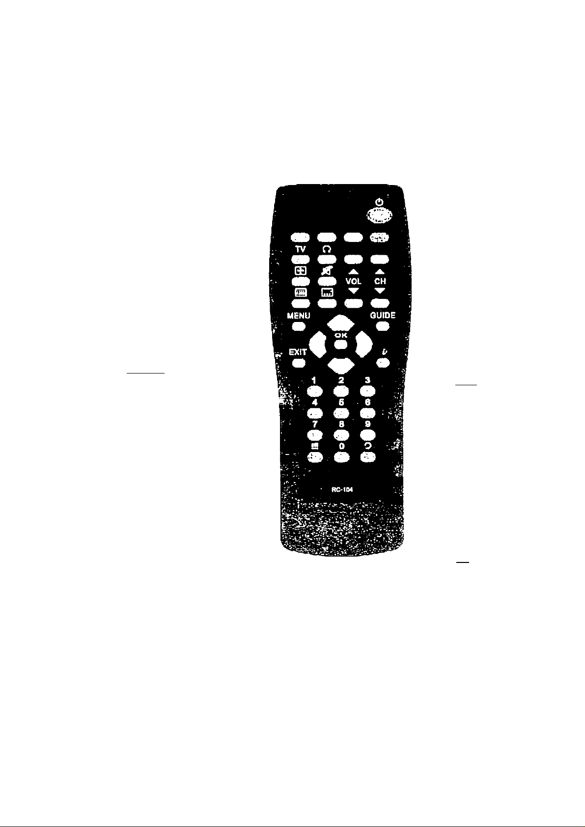
3.2 Control Panel
USER’S MANUAL
• SI; To turn your STB
oiVoff (standby mode)
• Number (0-9) keys: To
select channels directly
and other commands.
• B : To toggle between
present and previous
channels
• E r To enter the service
navigating channel
(Mosaic channel). Such
channel might not be
available if not being
sent by broadcaster
• 3S02- To obtain a list
of programs on
available channels.
This intormation is only
shown if your Service
Provider transmits
program information
• (Red): Application
defined function key
• (Green): Application
defined function key
« m (Yellow)
Application defined
function key
« S (Blue); Application
defined function key
• : Aspect ratio, to
change to 16:9 or 4:3
mode (only for CVBS
and S-Video output)
• ^ : To turn on
channel list
• 0 ; To turn on/oft
sound (only for
Analogue Audio Output)
O : To toggle for
selecting desired audio
sound track
msna
For Volume ad|uslment
(only for analogue
audio output)
For changing channels
m: To turn on/off
teletext
38: To toggle between
TV and Radio service
SWi: To go back one
level In the menus.
Buttons: To
move In up/down
directions in the menus.
To select TV and Radio
channels
Buttons: To move
in left/right directions
within the menus
SB :
To confirm choices
and selection of
highlighted item
To display the
“Main" Onscreen
Display (OSD)
U To call up the
program information
plates and extended
channel information in
program guide menu
Page 7
USER’S MANUAL
4 Installing Your Receiver
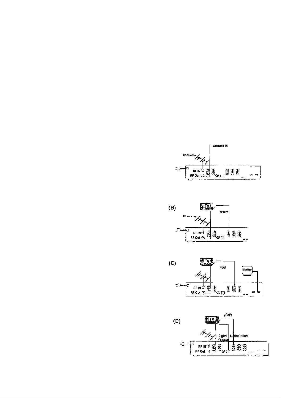
4.1 Connections
The following illustrations show some examples for connecting this HD receiver.
Select the connection that is best suited for your needs. Many other connections
may be possible when optional devices such as RF cable splitters are included in
your system. These devices may cause signal degradation and, if too many are
used, poor quality picture and sound may result. RGB and Monitor connectors can
not be used at the same time.
Terrestrial antenna/cable connection
Connect the TV antenna cable to the HD
receiver RF IN connector. Also connect the
cable between your TV Antenna IN and RF
Out connector on the rear of the receiver.
This connection allows your TV set to
receive normal analogue programs. (Refer
to A)
Adjust SW1 and SW2 according to the
formal supported by your TV. and it
contains four modes configuration: AA, AB,
BA and BB. (Refer to display output
configuration table on the rear panel of your
receiver). Under each mode, there are
several choices for connection.
AA/AB/BB: HD Mode
Video:
(A)
« Connect the YPbPr component video
output socket on your receiver to TV
YPbPr component video input. Be
sure to match the colors on the RCA
sockets with the colored plugs.
(Refer to B)
• Connect the RGB component video
output RCA socket to Monitor or TV.
Or you can choose D-sub connector
(monitor) on your receiver to monitor
Page 8

Audio:
USER'S MANUAL
or other display with such connector
interface. (Refer to C)
If your TV set is equipped with Dolby
Digital and/or MPEG audio decoding
capability, you may connect the
Digital Audio output by Optical or
Coaxial RCA socket on your receiver
to TV Digital Audio input Optical or
Coaxial RCA socket. {Refer to D and
E) You may also connect the digital
audio output to your AA/ receiver
assuming it is capable of decoding
Dolby Digital /MPEG digital audio
stream.
If your TV set and/or A/V receiver
does not support Dolby Digital/MPEG
decoding, you need to connect L/R
Audio output RCA sockets on your
receiver to stereo L/R Audio inputs of
TV set and/or A/V receiver. (Refer to
F). If your A/V receiver supports
Dolby Pro Logic decoder, you can
switch ON “Downmix-Surround”
function.
BA: SD Mode
Video:
• Connect the YPbPr component video
output socket on your receiver to TV
YPbPr component video input. Be
sure to match the colors on the RCA
sockets with the colored plugs.
(G)
YPbPr
S-Vicieo(Y/( ji
• Connect the CVBS composite video
output socket on your receiver to
TV/VCR CVBS video input socket.
• Connect the S-Video(Y/C) component
video output socket on your receiver
to TV S-Video input socket. (Refer to
G)
nFiM'i.’ s s:
RF Out
» ^
U M ^
Page 9

Audio:
USER’S MANUAL
if your TV set is equipped with Dolby
Digital and/or MPEG audio decoding
capability, you may connect the
Digital Audio output by Optical or
Coaxial RCA socket on your receiver
to TV Digital Audio input Optical or
Coaxial socket. (Refer to D and E)
You nnay also connect the digital
audio output to your A/V receiver
assuming it is capable of decoding
Dolby Digital /MPEG digital audio
stream.
If your TV set and/or A/V receiver
does not support Dolby Digital/MPEG
decoding, you need to connect L/R
Audio output RCA sockets on your
receiver to stereo l_/R Audio inputs of
TV set and/or A/V receiver. (Refer to
F). If your /W receiver supports
Dolby Pro Logic decoder, you can
switch ON "Downmix-Surround"
function.
Note: We suggest you to set volume
to maximum when recording the
program.
4.2 Switches for Video Output Mode Selection
Table 1. Display Output Configuration Table
sw
(1)
A A
A
B
(2)
B
A
YPbPr
1080i (1125)
576P
o76i PAL
RGB
Monitor*
lOSOi (1125)
1152i
6 B lOeOi (1250) 1080i(1250)
'Only one of RGB and Monitor output can be used at the same time
CVBS
S-Video
—
The display output table has four modes, SW1 and SW2 on the rear panel are for
mode selection.
Page 10

USER'S MANUAL
When using a HD monitor, which supports Y/Pb/Pr or R/G/B/HS/VS component video
input, you should turn the mode selection switches to AA. AB or BB. it depends on
which resolution your HD monitor can support.
When using a conventional TV, which supports Y/Pb/Pr, S-Video component video
input or CVBS composite video input, you should turn the mode selection switches to
BA.
If you use a Monitor or plasma display, turn the mode selection switch AA. AB or BB.
5 Operating Instructions: Knowing your basic controls
To become acquainted with the operations and functions of your receiver, you must
know how to use the control buttons on the Front Panel and the Remote Control.
The following segment is an introduction to features that you will most commonly
notice or use.
5.1 Switching On Your Receiver
Before you switch on your receiver please make sure the power mains is
plugged into a power outlet. Remember that as long as the power mains remains
plugged into your receiver, it will be in a constant “STANDBY" mode.
Turn on your TV and other connected audio/video equipment. Switch on your
receiver by pressing either the E button on the remote control or (!) on the front
panel. While the receiver is in normal viewing mode, the green LED lights up.
When not using the receiver, put your equipment in the “STANDBY’ mode by
pressing either one of the IS / O buttons again. When the red “STANDBY"
LED lights up, it indicates the receiver is in “STANDBY’ mode. The front panel will
show current time.
5.2 Information Plate
The Information Plate (l-Plate) shows
information about the program that you are
currently watching. The information plate
appears shortly, whenever you switch to a
new channel or when there’s problem with
signal reception. To show the information
1. FACrS HD Test Service
®t>8.‘07
Ei
9
.'«•0 OhOWJO Uarhmir Swini;
08t3(M»:00 St-nice 2
Page 11

plate, press the u button. Press 9'li^i to
remove the 1-Plate from the screen.
Program Guide
The Program Guide is a user-friendly
feature, which enables you to select, book,
and "peek in advance" programs. To enter
into the Program Guide, press In
the Program Guide on screen display,
program schedule is listed in chronological
order.
Section 6.1 of your User Manual will instruct
you to use the Program Guide efficiently.
USER’S MANUAL
«ran««: . MOt mo»* __i iiiv«'«
(sl«u*'V taoKad maliirl t'yVyntMrn
5.3 Changing Or Selecting Channels
There are several methods to change or select channel. You can either use the front
panel or the remote control buttons.
The followings are methods you can choose from:
• Select channels from the Mosaic interface. You have to first browse the Mosaic
channel by pressing the Mosaic button on remote control.
• Press Channel
A/T
on the remote control (channel switches according to
favourite channels setting).
• Directly enter a channel by using the number keys on the remote control.
• Use
A/V
to change channel. Unlike Channel
A/T
control channel movement is
not aligned with favorite channels setting.
• Use ®lo toggle between current channel and previously watched channel.
5.4 Audio Selection
The program you view may be accompanied by more than one audio soundtrack.
These soundtracks may be of different language or different type (Dolby Digital,
MPEG-1 or MPEG-2). You may press the audio button to select your desired
soundtrack. When you first press the button, the Audio OSD is shown on screen
listing all available soundtracks. The currently played track is highlighted. This OSD
will disappear in a short time, unless you press the Audio key again to select another
track before this OSD disappear.
10
Page 12

6 Using The Main
Your receiver comes with a directory of
features or the Main OSD. The Main is your
gateway to customising many of the
features offered by your receiver,
access the Main OSD. press the 23
button. The Main feature comprises
following categories of services;
1. Program Guide provides access to:
Programs Schedule
Programs Categorisation/Type
Booked Programs
2. TV/Radio Channels allows you to program:
i. Program Favourite channels
ii. Channel locking
iii. Channel deletion
3. Preferences allows you to access
I. Screen Format
ii. Display type
iii. MPEG Audio Level
iv. Audio Language Priority
V. Default Audio Mode
vi. Digital Audio
vii. Downmix-Surround
viii. Audio Balance
To
21!
the
USER’S MANUAL
1 Program guide
2 TV/Radio channels
3 Preferencos
4 Advanced Settings
5 Box Information
move
go to numbered Item
---------------------------------------
-
4. Advanced Settings allows you to program:
i. Parental Guidance
i. Change Password
it. Install
V. Restore Default Settings
V. Select Sates
5. Box Information to display the Software Version number and Serial ID of your
receiver.
6.1 Program Guide
By choosing the Program Guide banner on
the Main OSD. the Electronic Program
Guide (EPG) appears. The EPG is. in
classic terms, a TV Guide, except it is
presented on your TV screen! The EPG
■J f, Cfiinv* 0iwBr*ybeoWng hncie^ ; wov» . ' mev'f
flg booted dt!Sii»3 irl«T«loa
allows you to peek in advance, depending
on services provided by your Seivice
II
Page 13

USER’S MANUAL
Provider, a few days or up to one week of
TV programs and program information. By
using the arrow keys on either your receiver
or the remote control, you can roam the
EPG to access various channels and
programs.
In the grid highlight the program by pressing the arrow buttons. Once you have
selected the desired choice (the highlighted block will appear in a different shade),
press u to view the detailed description of the program. If the broadcaster does not
transmit detailed description of it, the text *'No descriptions available" will appear. If
you wish to see what programs are broadcasted on other channels, use the
button to access the list of all programs shown on the current and next days.
If you wish to book a future program,
highlight any program (beyond the current
time frame) by using the arrow buttons,
press SC confirm your selection. The
"Booking” window will appear allowing you
to book the program. Press 32 confirm
the booking, or (^Hii to exit the Booking
window. For more information on the
Booking feature, go to “Booked Programs”
to view the instructions. Note that if you
highlight a program currently broadcasted
on another channel and press 32’
program is not booked. Instead, the
receiver switches to that channel directly.
Coloured Hot Keys'*
On the Program Guide window, you v^ili
notice four coloured hot keys they provide
you Instant access to various services.
Boofcin
■M 1 mOirAL i
oiat iitjoim
имийпмпэ
Woukl you Mko to arm a timer for thli
proerem?
IV45 $•! 01Л)||701>1
• Category Selection
This special feature enables you to
screen out your preferred programs by
program Category or type. You can gain
access to this feature by pressing the
О button (yellow). Use the arrow
buttons to highlight the categories, and
press 32 to select or unselect any of
the categories. By default, the item "All
Calec^ory Selection
'ГГДП...1?
..... ...._
t D9ciiro*i^iY.;iac5i«SS
: • fiflq beck e »• ■ mov* • . mov*
Page 14

Categories’' is highlighted. You have to
cle-select that item before selecting
specific program type(s). As you select
some categories and go back to
program guide menu, only programs of
the selected categories will be visible.
Booked Programs
To review what programs are being
booked, press S (blue) to call up the
Booked Programs OSD. To cancel or
re-engage the booking, press H2- the
& symbol (the alarm clock)
disappears, then the timer is
disengaged. But, the program
information will remain in case you wish
to rebook the program. The cancelled
program will not be displayed the next
lime this window reappears.
USER’S MANUAL
y*l- Ol/OWOOl
<wVQf1 pn hoRli
6.2 TV/Radio Channels
You may highlight any channel in the list by
pressing up/down keys, then press 32 to
view that channel directly.
This feature allows you to personalise your
list of favorite channels, TV or Radio,
Highlight a channel by using the A/v
buttons, then press theS “hot key” (red) to
select or unselect. When a channel is
selected a 9 symbol will appear in the bar
to indicate the favorite status. When you
are changing channels using the 3^
keys, the receiver jumps to the
next/previous favorite channel, and skips
other channels.
If you wish to lock or unlock any channel,
simply press the® button (green) to do so.
When a channel is locked a fi symbol will
appear to indicate the locked status.
Whenever you wish to watch the locked
channel you will be asked to enter the
password. It you wish to delete any
1.^
TV/Radlo channels
1 CNN
2 SBC
3 OW/TV-5
4 Bloomberg
5 Arirang
change channel
. lock/unloek
TV^adlo channels
3 ICRT
4 CR Nev/s
5 CR Music
6 Stock - 1
7 Stock-2
Ov ctienge c}i8nn*i
lock/unloek
rrv|
9
9
9 &
X
S8B lavorilo
delete/undeiet^
S£l}
9
V
9
favorito
delete/iindctolo
Page 15

Channel, press the button (yellow) and a
"X" sign will be shown on that channel. You
may un-delete that channel by pressing the
same key again. If one or more channels
are deleted, on leaving the TV/Radio
channels menu, user will be asked to
confirm removal of those channels. Once
you confirm removing them, you cannot un
delete them. The only way to recover those
deleted channel is to do "Install" again.
Please use this feature very carefully.
To toggle between the TV (¡0 ) and Radio
() lists, press the [¡¡J button.
6.3 Preferences
From here, you may adjust various settings,
all according to your personal preferences,
such as language priority, audio mode, TV
type, Downmix-Surround and others. Note
that some settings in this segment are
related to AA/ equipment, which you are
connecting. Instructions on how to set each
item are presented below.
USER’S MANUAL
1 Screen Format
2 Display type
3 MEPG Audio Level
4 Audio Language Priority
5 Default Audio Mode( Dolby D
6 Digital Audio (pCM(stereo)^
7 Downmix-Surround
8 Audio balance
move toggle value
C»9 90 to numbered item
Wide )
CRT
Odb
On
R+7
1. Screen Format
If your TV set is in 4:3 format and the
transmission of a program happens to
be 16:9, the Normal/Letterbox mode
will give you a complete picture, but
black areas will appear at the top and
bottom.
Or you can choose the Normal/Center
Cut mode to play the program in a full
screen format. But information on the
left and right sides may be cut off.
If your TV set is in 16:9 format, then
set the mode at Wide. If a program
happens to be in 4:3, black areas will
appear at the left and right of the
screen in order to present the picture
in a correct aspect ratio.
T.etterbox
Center Cut
14
Page 16

Note that this selection only applies to
CVBS output.
2. Display type
This menu contains three options: CRT,
Plasma (low delay), and Plasma (high
delay). Normally, different display
equipment may have different delay in
picture which may cause slight
problem in lip sync. This feature allows
you to use ■</► to select your choice
according to your actual video display
equipment, in order to compensate this
delay. If your display is TV or CRT.
choose CRT. If your display is Plasma,
choose Plasma (low delay) or Plasma
(high delay) depends on which choice
appears to provide best performance in
lip sync.
USER’S MANUAL
16:9 Wide
3. MPEG Audio Level
From here you my adjust MPEG audio
level from -12 db to 0 db. This
adjustment is only for MPEG input and
system will detect MPEG Input
automatically.
4. Audio Language Priority
From here you may prioritise
languages for audio output. To
prioritise a language, press 3S to
highlight a language choice. Move the
choice up or down by using t!ie arrow
buttons. Press again to confirm the
priority.
Note that this priorit^^ applies when you
view new services. That is, the
receiver will select available audio
soundtrack with highest priority as the
default soundtrack. However, you may
select any available soundtrack at your
own will for each channel, and that
selection will not be affected by your
choice of language priority.
15
Page 17

USER’S MANUAL
5. Default Audio Mode
The Audio mode allows you to adjust the audio setting. You may choose
Dolby Digital, MPEG1 and MPEG2. Use ◄/► to select your choice. Like
Audio Language Priority selling, this audio mode setting determines your first
choice of soundtrack based on audio mode, and you may select any
soundtrack channel by channel, regardless of the audio mode setting made in
this menu.
If the default Audio Mode is Dolby Digital, and the input signal only contains
MPEG-2, the default Mode will change to MPEG-2 automatically. If the Audio
Mode is set to Dolby Digital, the QTR2140 will automatically select a Dolby
Digital soundtrack when It is available. We especially recommend this
selection if you will be connecting your QTR2140 to a TV or A/V receiver then
can decode Dolby Digital (look lor the logo) or Dolby Surround Pro
Logic (look for the logo).
6. Digital Audio
For each Audio Mode, you can have different Digital Audio Selcclion Options.
(Refer to Table2 Digital Audio Selection Table)
Table 2: Diqilal Audio Selection Table
Default Audio Mode
Digital Audio Selection Options
1. Bitslream
AC-3
2. PCM (stereo)
3. Off
MPEG-2
Same as above
1. PCM (stereo)
MPEG-1
'Bitslream: select this if your TV or Л / V receiver has a digital audio input and can decode Dolby
Digital
*PCM {stereo): select this if your TV or A / V receiver has a digital audio input but can not decode
Dolby Digital
*Off: .select this if you want the digital audio output to mute when a Dolby Digital program is being
received.
2. Off
7. Downmtx-Surround: You can select Downmix-Surround on/off by pressing
and SS
On: Surround information will be included in stereo output (Lt/Rt)
Off: Pure stereo audio output (L/R)
8. Audio Balance: You can adjust the value from L+7 to R+7, 15 selections.
The selection “0” means balanced (equal level) output on the two front
speakers.
6.4 Advanced Settings
Different from Preference, in segment 6.3, the settings in this segment are related to
programming your receiver. Again, some of the settings, especially 3, may require
assistance from your Seivice Provider.
16
Page 18

1. Parental Guidance
USER’S MANUAL
Using you may select the limit
amount; None, Biock G, Block PG,
Block M, Block MA, Block AV, Block
RA, and Block all. Your receiver will
automatically block programs that are
unsuitable to children under the age
limit you have set. For example, if you
choose "Block PG" and the programs
with rating equal to or above PG. then
the receiver will ask viewer to enter
password before viewing that program.
However, not all transmissions carry
the signal to activate this function.
2. Change password
From here you can change the
password. Once the now password is
set DO NOT FORGET IT! Without the
password, you cannot access any
functions that require you to provide
the correct password! The default
password is 0000. if you forget your
password, please contact customer
service for help.
Advanced Settings
1 Parental Guidance
2 Change password
3 Install
4 Restore Default Settings
5 Select Region
move toggle value
\ go to niimbcrod Item
1 Parental Ouidnnco
I fc:\.c I
3. Install
When the receiver is set up, conduct
the channels search by selecting the
"Auto scan channels" function.
® Auto Scan channels
Auto Scan channels provides an
easier way to conduct channel search.
It does not require you to enter any
particular parameter. This function is
strongly recommended for regular
users. However, user should be
aware of the fact that all existing
channels will be removed as soon as
you confirm start of auto scan.
17
Auto seen channel»
Manual channel search
start searching exit
move
s«i number
Page 19

In the Auto Scan channels OSD. all
channels found will be listed. The
channel search may take a few
minutes. If you abort auto scan during
the scan process, some channels may
not be available to you.
« Manual Channel Search
In the “Manual channel search"
window you can set the channel
search by pressing left or right button
Ihen 02 lo select the physical channel
you want to search.
UbbK'ii MANUAL
4. Restore Default Settings
If you wish to reset all previous new
settings, you can use this feature to do
so. Once you decide to restore default
(factory) settings, all previous settings
will be lost. Please be very careful
before you confirm this action.
5. Select Region
Using <!> you may select the
relevant region: New South Wales,
Victoria. Queensland, South Australia,
Western Australia, Tasmania. North
Territory. This setting will give you the
correct current time when the receiver
is in Stand-By mode.
6.5 Box Information
From here, you can get general information
about the Receiver ID, softw'are and
hardware version on which it is operating.
Box Information
SW Version T2140.C1-1.0.?
Serial !0 42949B7295
Model Name QTn2M0
HV/ Desciliiligii T2140.C1-4W1B/F32
iS
Page 20

6.6 Software download
When your set-top box detected new
software, there will be a pop-up menu
showing on TV, we suggest you to select
YES for software download. After selecting
YES, the system will ask you not to press
any button or power off during the
download process. The download process
requires around 10 minutes. After
completion of SW upgrade, STB shall
reboot itself with the new software.
7 Glossary
USER'S MANUAL
'' A
New 3oftv/are VQreion found. Do you
want to upgrade now?
yos no
__
/
A/V; A connector for the transmission
of audio, video and status signal.
Channel Banner: A small window
with simple navigation tools to displays
information about individual channels.
Menu: An onscreen display offering a
list of commands to select from.
Normal viewing: The state of your
receiver when no menus or windows
are displayed on the screen, and the
current channel is tuned.
Parental Lock: A feature enabling
parents to “lock" programs that they
consider unsuitable for children’s
viewing. A “locked" program can only
be “unlock” with the PIN number.
Password: A personal 4-digit number
for controlling specific features of the
receiver including access to locked
channels.
Program Guide: The instantaneously
and continuously updated electronic
program guide for quick and easy
reference or program selection.
Reminder; Message displayed on the
screen informing viewers that a
booked program is about to start.
Service: Also called a channel to
which a TV or receiver is tuned. A
service provider offers one or more
services.
Service Provider; the Company that
provides one or more services to the
subscribers or viewers.
Integrated Receiver Decoder (IRD):
A device that is capable of decoding
and tuning digital signals and
converting these signals into a tormal
that is understood by your TV set.
Aside from decoding signals, it also
verifies access rights.
Standby mode: A condition in which
your receiver allows retrieval of up
dated information from input signals.
VCR: Abbreviation for Video Cassette
Recorder.
I9
Page 21

; ;:■- - ' '“‘X- ^ *
8 Troubleshooting
VOCr\ O IVIMl'tUMU
Problem Possible causes
The display on the panel Power Mains cable is not
does not light up/is not lit connected
No sound or picture
I ho remote control Is not Battery exhausted
working
The A/V cord is nol properly placed
Wrong selection ol output mode
Florescenl light intcriering with the
remote control
Remote control is incorrectly aimed Aim Ihe remote control at llie receiver
What to do
Check that tho mains cable is plugged In to
the power socket
Check the cable connections and other
equipment connected to your receiver
Try another output configuration
Change the batteries
Switch off tfie light
What to do if you can't solve the problem
If you have tried all of the actions suggested above, without solving the problem, please
contacl the Panasonic Customer Care Centre on 132 600 for additional help.
20
Page 22

9 Technical Specifications
USER'S MANUAL
Terrestrial
Tuner/Demodulator
System
Video
Audio
Rear panel Interface
User interface
Power requirements
Environmental Condition Operating Temperature 32^K“108'F (0-40'C)
ino'Jt ?roauoncv
Siandatd
Channel Bandwidth
COFDM System
Demodulaiion Ivne
Guard Interval
FEC
CPU
Transport
Flash memory
System memory
EEPROM
Standard
Video Memory SDRAM
Field / Frame rale
HD/SD, Interiaced/progressive output
mode supported
Aspect Ratio
Standard
Samplinq rate 32.44.1.48 and 96 KHz
Dinilal Audio Output format 1EC-60958/1EC6I937
RF input connector / Loop through
Output
CVBS/ Stereo Output
Y/C output S-VHS
Y/Pb/Pr component video RCA connectors
R/G/B/HS/VS
Diaital Audio SFDIF
Serial port
Mode Selection Switches
Front panel
Mains input voltaqe
Mains input frequency
Power consumption
Dimension (WxDxH)
Weight
VHF. UHF Band
DVB-T (ETSI 300 744)
7MHz, Australian Channel
2K. 8K carrier
Hierarchical supported
QPSK. I6QAW. 64QAM
1/32,1/16,1/8, 1/4 active
symbol duration
1/2, 2/3, 3/4, 5/6, 7/8
32-bil RISC
DVB Demultiplexor
4 MB
4 MB
32 K8
MPEG-1 ISO/IEC 11172-2 and
MPEG-2 MP(i)ML and MP<J5»HL
ISO/IEC 13818-2
Up to 1G MB
SO/25 Hz
1080i(112b)/5/6P/5/6i/
1080i{1250)
4:3, 16:9 and Letter box
supported
MPEG-1 ISO/IEC 11172-3 layer
1 and layer II /
MPEQ-2 ISO/IEC 13818-3
Dolby Diqltal AC-3
lEC type 75 ohm
2 sets of RCA connectors
RCA connectors
DB-15iFemale)
Coaxial / Optical
RS-232 iFemale, DB-9)
SW1.SW2
8 Keypads, 7-segment (4 digits)
display and 3 LED indicators
IR Sensor
100-250VAC--
50/fi0 H2
Normal operation 15W
Standby mode 5W max.
Max. 33W
365 X 250 X 60 (mm)
2.45 kg
Copyright © 2001 Quanta Network Sysicmv Inc. All Rights Reserved.
21
 Loading...