

Page 1
DIN 48 SIZE
07/2004
QM4H
DIGITAL TIMER
Timers
Possible to set and change the time with front digit switches easily
during the power off.
Furthermore single unit has a time range of 0.01s to 9990hrs!!
FEATURES
1. Possible to set and change the time and
the time range even when the power is off.
2. Selectable 8 different time ranges with
front digit switches.
3. [QM4H-S Type]
It can select the mode with MODE switch.
T.D. MODE: Time delay 2C (2 Form C)
S Type
(with MODE switch)
INST. MODE: Time delay 1C (1 Form C)
Instantaneous 1C (1 Form C)
[QM4H-G Type]
Reset and stop signal input enable to
external control.
G Type
PRODUCT TYPES
Product name
S Type QM4H
digital timer
G Type QM4H
digital timer
Note: Time delay directional subtraction types are also available by order
Time delay
direction
Addition
Time range Operating mode Contact arrangement Operating voltage Part number
Power ON delay
0.01s/0.1s/1s/0.1min/
1min/0.1h/1h/10h
(8 time ranges)
Power ON delay
(with reset and
stop terminals)
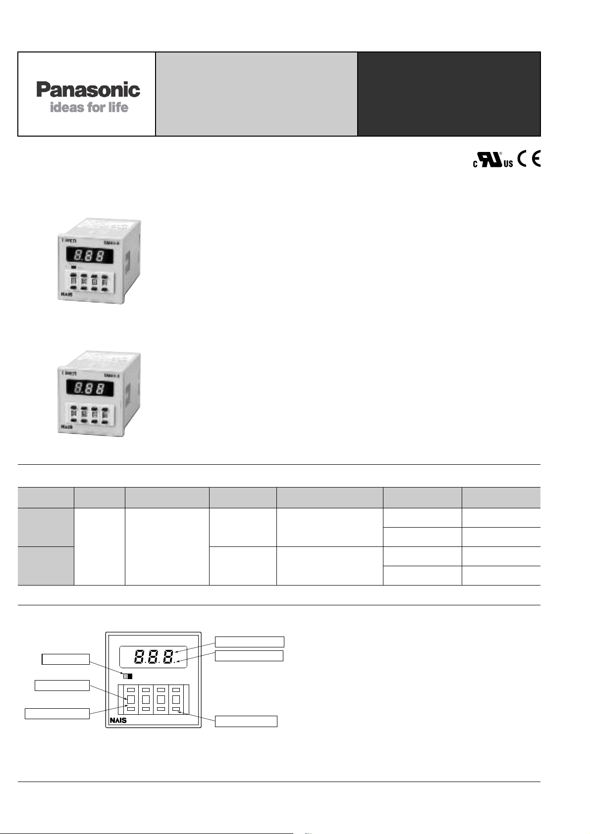
PART NAMES
QM4H-S
-+-
888S
+--+
+
Elapsed time display
Time delay indicator
(OP.LED)
Time range switch
MODE switch
(QM4H-S type only)
Set time display
Time setting switch
(3 digits)
TIMER
MODE
T.D.
INST.
T.D. mode: Time delay 2C
INST. mode: Time delay 1C
and Instantaneous 1C
(Use MODE switch on front)
Time delay 1C
Protective construction:
QM4H: IP40
with cover AQM4801: IP50
with cover AQM4803: IP64
12 to 48 V AC/DC QM4HS-U2C-48V
100 to 240 V AC/DC QM4HS-U2C-240V
12 to 48 V AC/DC QM4HG-U1C-48V
100 to 240 V AC/DC QM4HG-U1C-240V
44
Page 2
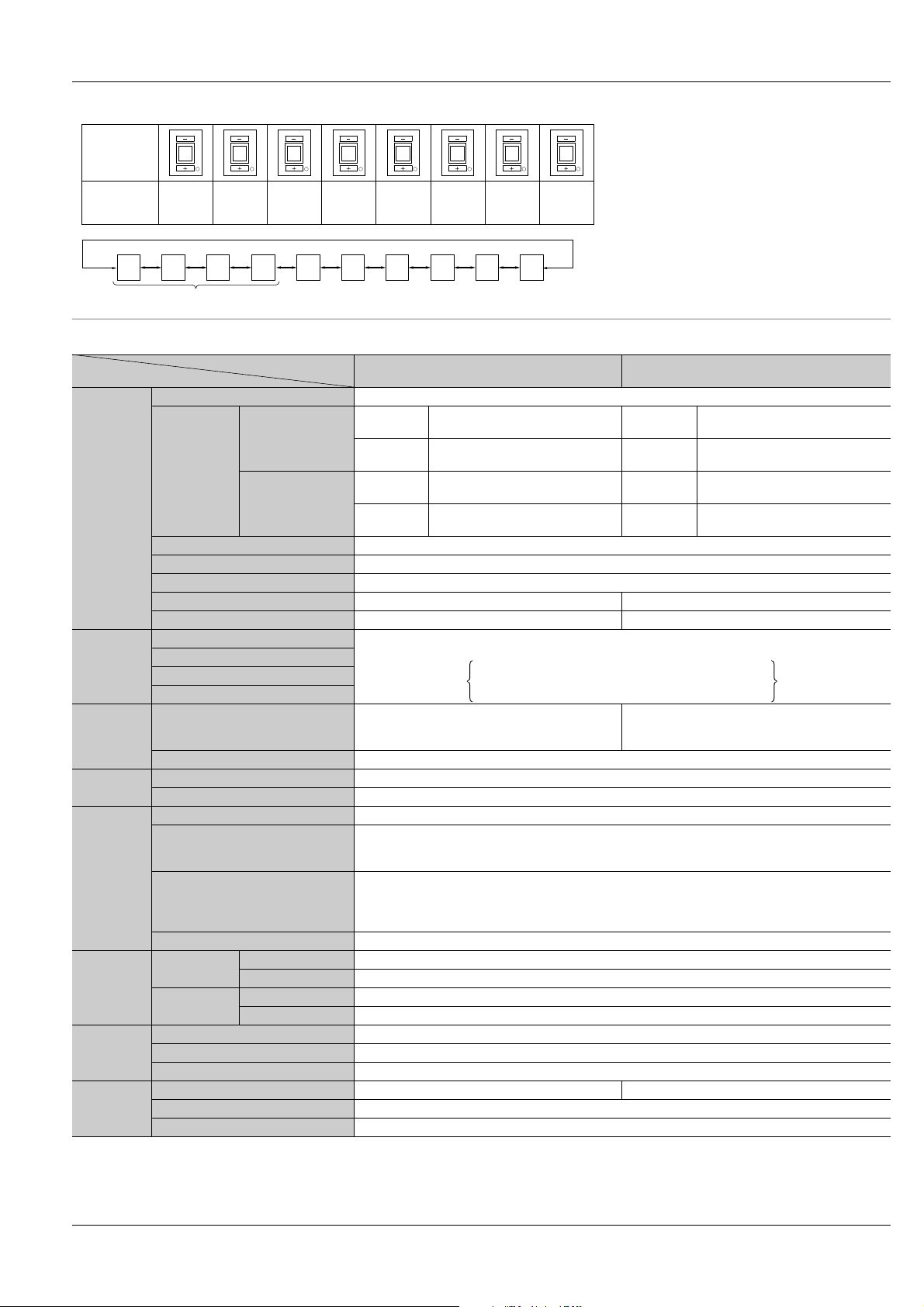
TIME RANGE SETTINGS
07/2004
QM4H
Time range
switch
Operating
time range
.01
S
Note that there are two settings with the same range.
0.1
S
.01
S
0.01s
to
9.99s
0.1
S
0.1s
to
99.9s
.01S0.1
SMH
1s
to
999s
S
0.1
M
to
0.1
1min.
to
999min
M
0.1min.
99.9min
SMH
0.1
H
0.1
H
0.1h
to
99.9h
1h
to
999h
10
H
10
H
10h
to
9990h
SPECIFICATIONS
Item
Type
Rated operating voltage 12 to 48 V AC/DC and 100 to 240 V AC/DC
During time
delay
After time
delay
During time
delay
After time
Rating
12 to 48 V
AC/DC
Rated power
consumption
100 to 240 V
AC/DC
delay
Rated frequency 50/60 Hz common (at AC)
Rated control capacity 5 A, 250V AC (resistive load)
Time range 0.01s to 9990h, Selection of 8 range: 0.01s/0.1s/1s/0.1min/1min/0.1h/1h/10h
Operation mode Power ON delay Power ON delay (with reset and stop terminals)
Min. input signal width — 20ms (Reset and Stop inputs)*
Operating time fluctuation ±(0.01%+0.05s) in case of power on start
Time
accuracy*
Temperature error
1
Setting error
Voltage error
T.D. mode: Time delay 2C
Contact
Contact arrangement
INST. mode: Time delay 1C and
Instantaneous 1C (Use MODE switch on front)
Contact material Silver alloy
Life*
3
Mechanical (contact) Min. 10
Electrical (contact) Min. 105 (at rated control vltage)
Allowable operating voltage range 85 to 110% of rated operating voltage
Breakdown voltage
(Initial value)
Electrical
Insulation resistance
(Initial value)
Reset time Max. 0.1s
Functional 10 to 55 Hz: 1 cycle/min. single amplitude of 0.25 mm .010 inch (10 min on 3 axes)
Destructive 10 to 55 Hz: 1 cycle/min. single amplitude of 0.375 mm .015 inch (1h on 3 axes)
Functional 98 m/s2 (4 times on 3 axes)
Destructive 980 m/s2 (5 times on 3 axes)
Mechanical
Operating
conditions
Vibration
resistance
Shock
resistance
Ambient temperature –10°C to 55°C +14°F to +131°F
Ambient humidity Max. 85% RH (non-condensing)
Air pressure 860 to 1060 hPa
Mass (Weight) Approx. 130 g 4.59 oz Approx. 120 g 4.23 oz
Others
Available standards UL, C-UL, CE
Operating display LED (red), During time delay: blinking, After time delay: OFF
Notes: 1. Unspecified measuring conditions are rated operating voltage (in case of DC type, ripple rate of 5% or less), ambient temp. 20°C 68°F,
and stop time 1 second.
2. Reset start applies to QM4H-G type.
3. Excluding switches
4. Note that if the QM4H-G type is set to zero “0” and a STOP signal is input, output will begin when the power is turned on.
QM4H-S QM4H-G
12 V DC, 48 V DC: Max. 1.5W
12 V AC, 48 V AC: Max. 3.0 VA
12 V DC, 48 V DC: Max. 2.5W
12 V AC, 48 V AC: Max. 5.0 VA
100 V DC, 240 V DC: Max. 1.5W
100 V AC, 240 V AC: Max. 3.0 VA
100 V DC, 240 V DC: Max. 2.0W
100 V AC, 240 V AC: Max. 4.0 VA
±(0.005%+0.03s) in case of input reset start*
During time
delay
After time
delay
During time
delay
After time
delay
12 V DC, 48 V DC: Max. 1.0W
12 V AC, 48 V AC: Max. 2.0 VA
12 V DC, 48 V DC: Max. 1.5W
12 V AC, 48 V AC: Max. 3.5 VA
100 V DC, 240 V DC: Max. 1.0W
100 V AC, 240 V AC: Max. 2.5 VA
100 V DC, 240 V DC: Max. 1.8W
100 V AC, 240 V AC: Max. 3.2 VA
2
Operating voltage: 85 to 110% V
Temperature: –10 to +55°C +14 to 131°F (20°C 68°F)
Stopped time: 0.1 sec to 1 hour
Time delay 1C
7
Between live and dead metal parts, between input and output,
between contact sets, between contacts
Min. 100 MΩ (at 500 V DC megger)
Between live and dead metal parts: 2, 000 Vrms for 1 min
Between input and output: 2, 000 Vrms for 1 min
Between contact sets: 2, 000 Vrms for 1 min
Between contacts: 1, 000 Vrms for 1 min
4
45
Page 3

QM4H
3
2
18
7
6
54
MODE
NC
NO
COM
NC
NO
Operating
voltage
COM
T.D. INST.
Notes:
1. Operating voltage signs in parentheses ( ) indicate the polarity
of the DC type.
2. is a time delay contact.
is an instantaneous contact.
Operating
voltage
45
6
7
81
2
3
NO
NC
COM
RESET
STOP
COM
07/2004
DIMENSIONS
• S Type • G Type
MODE
INST.
888S
+--+-+-+
QM4H-S
TIMER
8
+
TIMER
T.D.
48
1.890
-8-
+
QM4H-G
-
8
+
(units: mm inch)
Tolerance: ±1.0 .039
Terminal layouts and Wiring diagrams
6
.236
-
S
+
72.5
2.854
12.9
.508
44.5
1.752
• QM4H-S Type
Panel cut-out dimensions
+0.6
45
0
+.024
1.772
0
+0.6
45
0
+.024
1.772
0
+0.6
45
0
+.024
1.772
0
A
Dimensions A when n products
are installed continuously:
A = (48∗n–2.5 )
+0.6
A = (1.890∗n–.098 )
0
OPERATION MODE
• QM4H-S Type
1) T.D. mode
Power supply
Time delay contact
(N.O. contact)
1-3 or 6-8
OP.LED
2) INST. mode
Power supply
Time delay contact
(N.O. contact) 6-8
Instantaneous contact
(N.O. contact) 1-3
OP.LED
ON
T
ON
T
ON
9.5
.374
Panel Mounting Diagram
+.024
0
ON
ON
(85.4)
(3.362)
Mounting frame (AQM4812: supplied)
(AT8-DA4 can also be used for
mounting frame. Sold separately)
Mounting screw
(supplied with mounting frame)
Panel (Thickness: 1 to 5 mm .039 to .197 inch)
• QM4H-G Type
OFF
OFF
OFF
OFF
OFF
Power supply
Reset 1-3
Stop 1-4
Time delay contact
(N.O. contact) 6-8
OP.LED
Lit Blinking Blinking slowly
* Set the reset inputs 1 to 3 and stop inputs 1 to 4 to 20 ms or higher.
* When shorting a signal, please set the inter-terminal resistance to 1 kΩ or less,
and the inter-terminal residual voltage to 2 V or less.
When releasing, please set the inter-terminal resistance to 100 kΩ or greater.
MODE
ON
ON
ta t1 t2T
ON
ON
ON ON
T: Setting time t1+t2 = T ta<T
TD mode: Time delay 2C
INST mode:
Time delay 1C and
Instantaneous 1C
*Use MODE switch on front
• QM4H-G Type
PRECAUTIONS IN USING THE QM4H
1. Avoid locations subject to flammable
or corrosive gases, excessive dust, oil,
vibrations, or excessive shocks.
2. Since the main-unit is made of
polycarbonate resin, avoid contact with or
use in environments containing methyl
alcohol, benzene, thinners, and other
organic solvents; and ammonia, caustic
sodas, and other alkaline substances.
3. Power supply superimposed surge
protector
Although a surge protector will withstand
standard-waveform voltage with the
values in the next table, anything above
this will destroy the internal circuit. You
46
should therefore use a surge absorber.
12 to 48 V AC/DC 100 to 240 V AC/DC
1,000 V 6,000 V
• Surge waveform
[±(1.2×50) µs uni-polar full wave voltage]
4. In order to maintain the characteristics,
do not remove the timer case.
5. When installing the panel, use the
supplied AQM4812 main-unit
mounting frame. Note that the AT8-DA4
is also available for sale separately.
6. If you change the operating voltage,
be sure not to allow leak current into
the timer.
7. Avoid leaving the unit powered
continuously. Leaving the unit
powered up with output set to ON
continuously for a long period of time
(about 1 month or more) will wear out
the electronic components. If you will
be keeping it powered continuously,
combine with a relay to create the
circuit shown below:
R
T
R
RT
 Loading...