

Page 1
ORDER NO. VMD0109026C8
Digital Video Camera/Recorder
• Q-MECHANISM
(Including Q1, Q2&Q3)
© 2001 Matsushita Electric Industrial Co., Ltd. All rights reserved. Unauthorized
copying and distribution is a violation of law.
Page 2
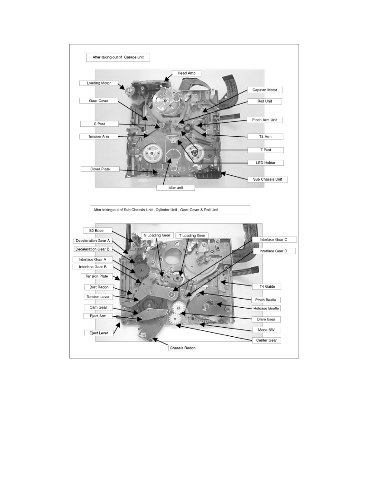
1 MECHANICAL PARTS LOCATION
1.1 UPPER SIDE
Page 3

1.2 BOTTOM SIDE
1.3 SENSOR POSITION
Page 4

2 SERVICING FIXTURES& TOOLS
2.1 FIXTURES& TOOLS FOR DISASSEMBLY& ASSEMBLY
No. Parts number Parts Name Q´ty New Remarks
1 VFK1390 Precision Driver 1 •
2 VFK1444 Gear Driver 1 •
3 VFK1444Q2 Gear Driver for Q2 & Q3mecha. 1 •
4 VFK1650 Cut Washer Jig(0.86) 1 •
5 VFK1649 Cut Washer Jig(0.65) 1 •
6 VFK1024 Molytone Grease 1 •
2.2 FIXTURES&TOOLS FOR MECHANICAL ADJUSTMENT
No. Parts number Parts Name Q´ty New Remarks
7 VFK1278 Post Adjustment Driver 1 •
8 VFK1638 Capstan Tilt Adj. Jig 1 •
9 VFK1641 Envelope Detecor Board 1 •
10 VFM3110EDS(PAL) DV Alignment Tape 1 -- or VFM3010EDS(NTSC)
11 VFK1395 232C(M3) I/F Cable 1 -- "TATSUJIN" system
12 VFK1308E Measuring Board 1 -- "TATSUJIN" system
13 VFK1309 EVR Connecor Board 1 -- "TATSUJIN" system
14 VFK1309EX Connection Adaptor
15 VFK1317 30pin Flat Cable 2 -- or VFK1517(New - 300mm)
16 VJA0941 DC Output Cable 1 -- "TATSUJIN" system
-- "TATSUJIN" system
"TATSUJIN" system
Page 5
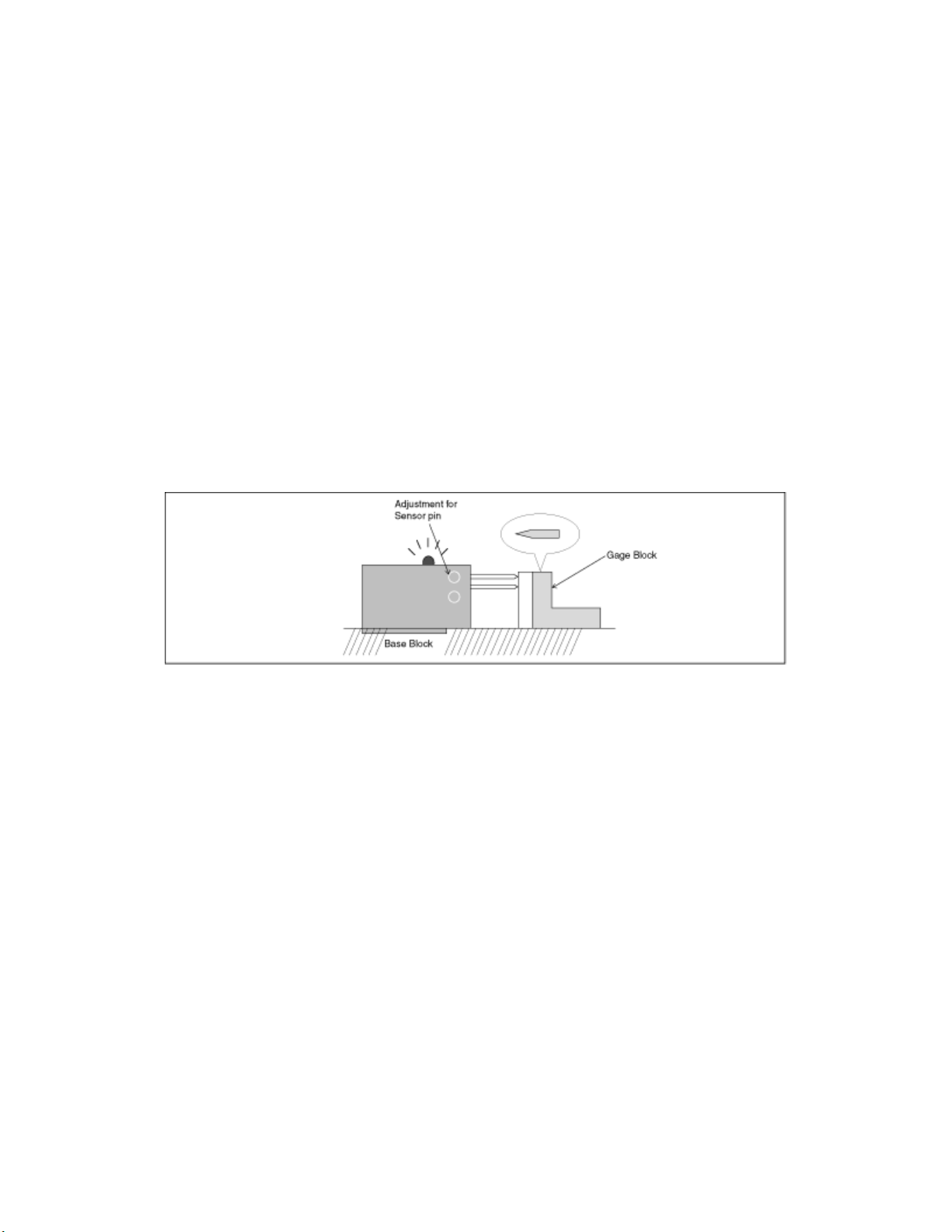
2.3 MAINTENANCE FOR CAPSTAN TILT ADJUSTMENT JIG.
1. Keep applying oil for preventive oxidation on base block.
Glove should be used when you apply oil.
2. Do not apply pressure to this jig.
3. If Brightness of LED become weak, Battery (SUM4 X 2) in the top of box
should be changed.
4. Inspect sensor pin regularly as following.
A. Put Gage Block to sensor pin.
B. Confirm LED is lit.
If not, adjust sensor pin by rotating a screw.
Page 6
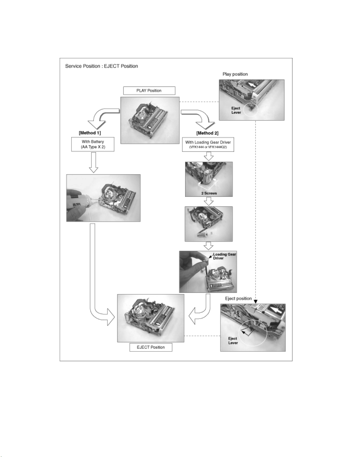
3 DISASSEMBLY PROCEDURE
3.1 PREPARATION FOR
DISASSEMBLY
Page 7
3.2 DISASSEMBLY PROCEDURE
No. Item Fig. Procedure
Fig. D1-1 1) Remove 3 screws. (Q1 &2 have 4 screws) 1 Cassette Up Unit.
Fig. D1-2 2) Take coupling portion off from both S &T sides.
*2 H Amp Unit.
(Only Q1 & Q2)
3 Cylinder Unit & RT Flex. Flame.
4 LED Holder, Cover plate & Idler U.
6 Pinch Arm & Center Gear
7 Rail Unit
8 T-Loading Gear & S-Loading Gear Fig. D8 1) Take T-Loading Gear out.
9 Gear Cover Fig. D9 1) Remove a screw and slide Gear Cover to take out.
10 Pinch Beetle & Release Beetle Fig. D10 1) Remove a washer and take Pinch Beetle and Release Beetle out together.
11 Tension Lever & Eject Arm. Fig. D11 1) Remove a screw and take Tension Lever out.
12 Interface Gears Fig. D12 1) Remove 4 Gears.
13 Cam Gear Fig. D13 1) Remove Cam Gear.
14 Chassis Radon Fig. D14 1) Remove a washer.
15 Boat Radon Fig. D15 1) Remove Boat radon.
16 Drive Gear Fig. D16 1) Remove Drive Gear and a White Waher underneath.
17 Capstan Holder & Capstan Motor
Flex.
*19 Mode Switch , Deceleration Gears & Tension
Plate.
Fig. D2-1 1) Remove a screw from Shield case.
Fig. D2-2 2) Take Cylinder Flex. From connector.
Fig. D2-3 3) Remove a screw from H Amp Angle.
Fig. D3-1 1) Remove a screw from RT Flex. Flame.
Fig. D3-2 2) Remove 3 screws and then take Cylinder Spring out.
Fig. D3-3 3) Remove a screw and take RT Flex. Flame out.
Fig. D4-1 1) Pull up and remove LED Holder.
Fig. D4-2 2) Move LED Flat Cable out of position and unhook 2 springs.
Fig. D4-3 3) Remove 5 screws and remove Cover Plate & Idler U.
Fig. D5-1 1) Remove 4 screws. 5 Sub Chassis Unit
Fig. D5-2 2) Remove a screw and unhook a spring from Pinch Arm.
Fig. D6-1 1) Remove Cut Washer and take Pinch Arm out.
Fig. D6-2 3) Take Center Gear Spacer out.
Fig. D7-1 1) Make half loading until
Fig. D7-2 2) Disconnect Connection Arms.
Fig. D7-3 3) Remove 4 screws.
Fig. D171
Fig. D172
Fig. D181
Fig. D182
Fig. D19 1) Take Mode Sw out.
2) Take Center Gear out.
Connection Arm comes out.
a) Hold Loading Gear side.
b) Disconnect connection arms.
2) Remove Cut Washer on S-Loading Gear and take S-Loading Gear out.
* Removed Cut Washer can not be used again.
2) Remove a washer and take Eject Arm out.
1) Remove 2 screws and take Capstan Holder out.
* It is not necessary to remove 2 screws for New Capstan Holder. Because it
shapes screw.
2) Remove 3 screws and take Capstan Motor out downword.
1) Remove 2 screws and take Loading Motor Unit out. 18 Loading Motor unit & Mechanism Interface
2) Remove 4 screws and dissolder at Mode Sw.
2) Remove a washer and take Deceleration Gear (A) out.
Page 8

4) Remove 2 washers and take Tension Plate.
*20 T4 Guide , Eject Lever , Pulley Cover &
Pulley.
*21 S3 Base U. Fig. D21 1) Remove a screw for S3 adjustment and take S3 Base U.
Fig. D201
Fig. D202
Fig. D203
1) Remove a screw and take T4 Guide out.
2) Remove a washer and take Eject Lever out.
3) Remove 2 screw and take Pulley Cover out.
4) Take Pulley out.
* 1) Procedure 2 for H.Amp Unit is applied only Q1 & Q2
mechanism.
2) Procedure 19 - 21 can be changed in order.
Fig. D1-1
Fig. D1-2
Page 9
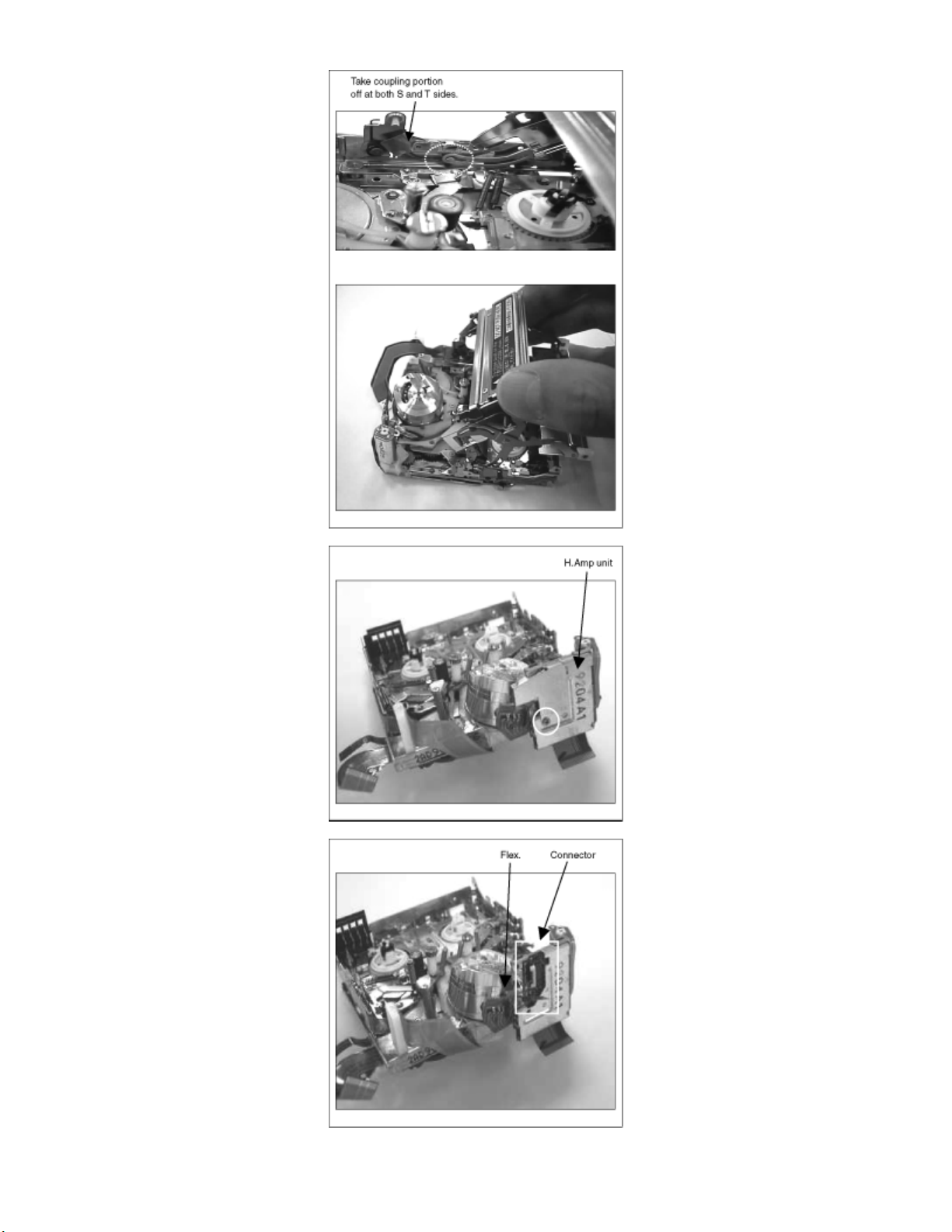
Fig. D2-1
Fig. D2-2
Fig. D2-3
Page 10
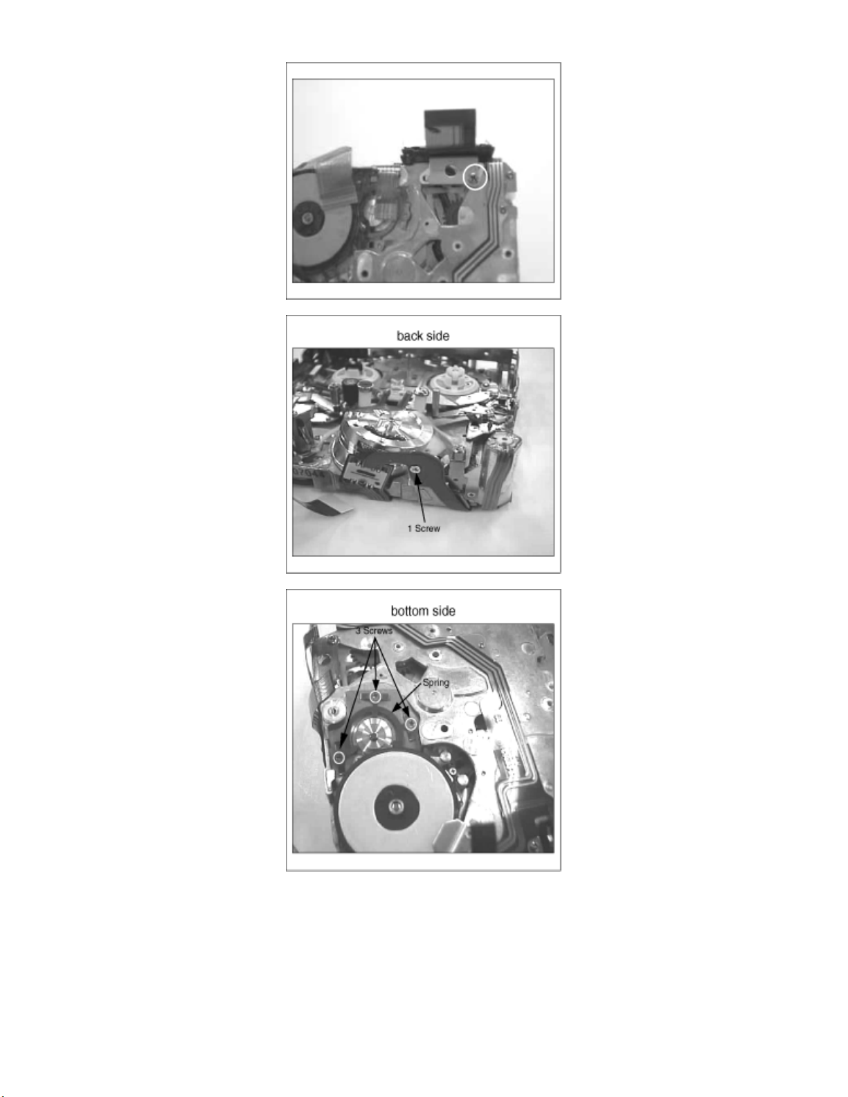
Fig. D3-1
Fig. D3-2
Fig. D3-3
Page 11
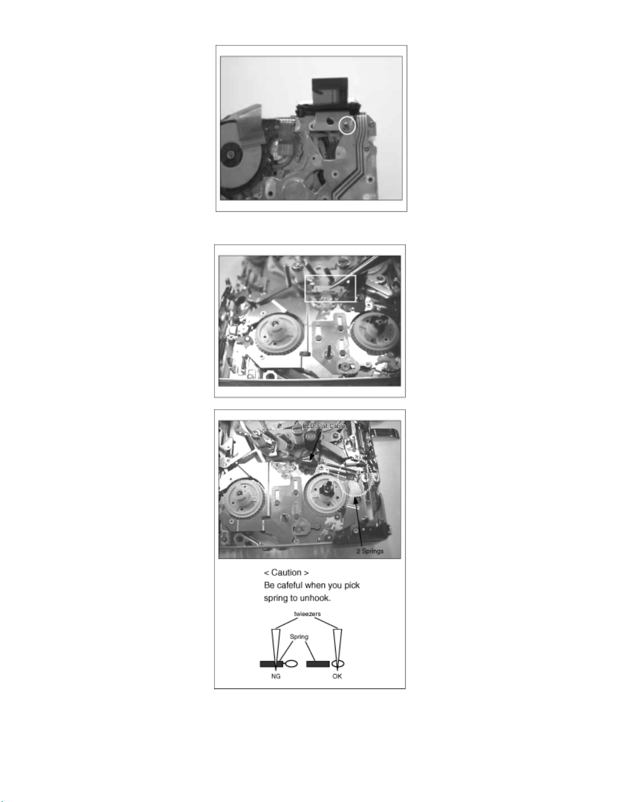
Fig. D4-1
Fig. D4-2
Fig. D4-3
Page 12
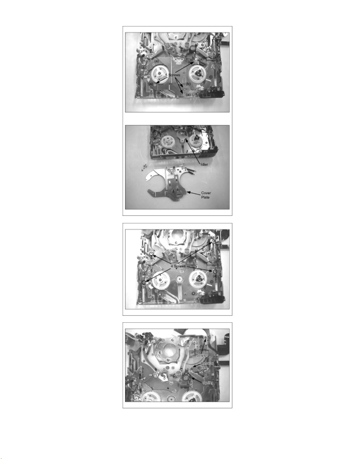
Fig. D5-1
Fig. D5-2
Fig. D6-1
Page 13
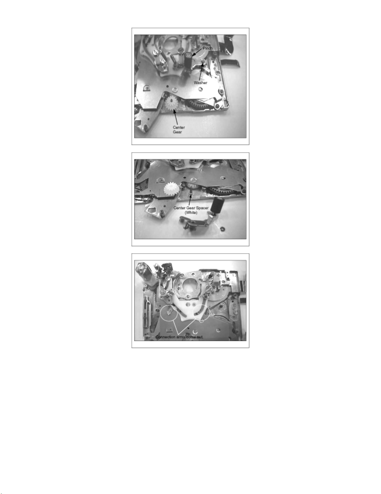
Fig. D6-2
Fig. D7-1
Fig. D7-2
Page 14
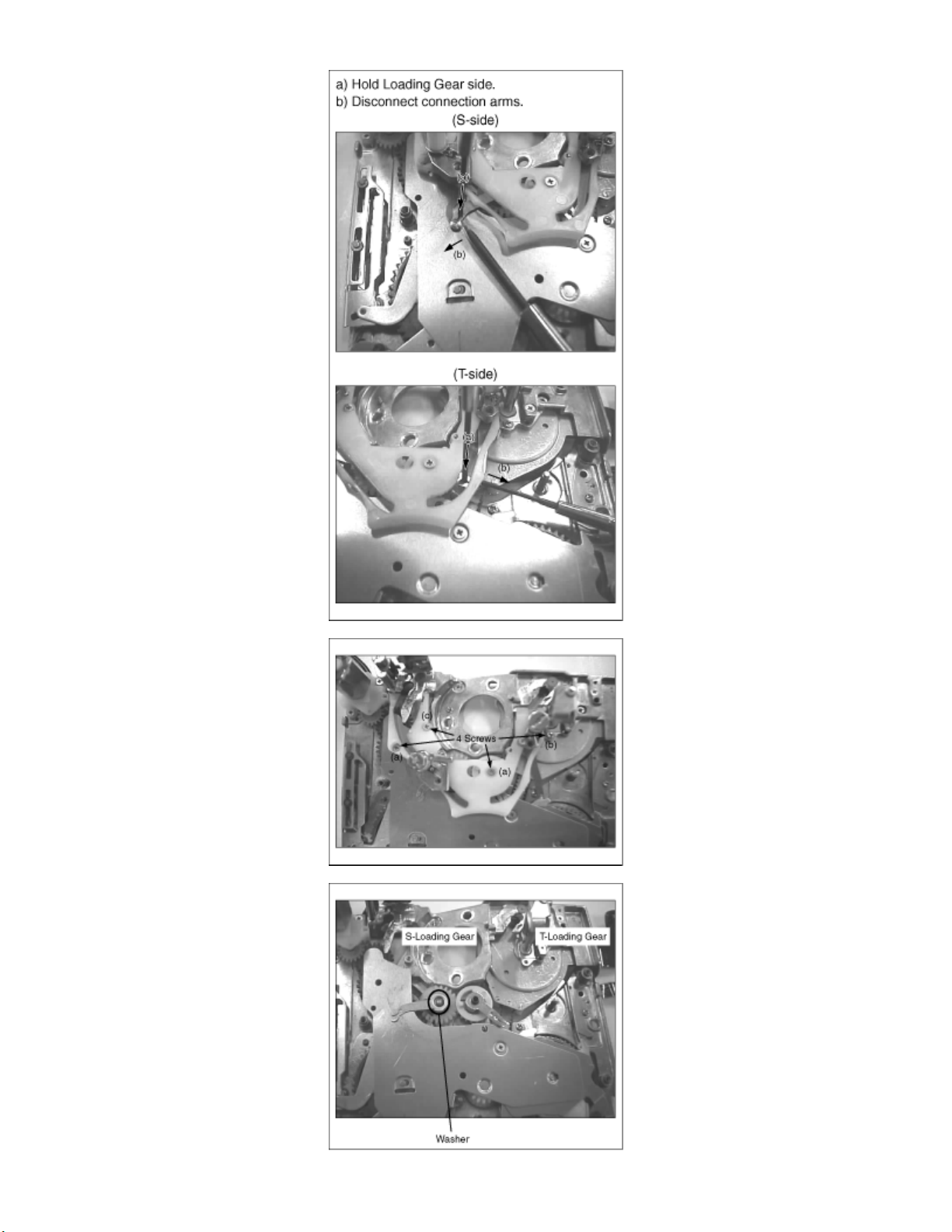
Fig. D7-3
Fig. D8
Page 15

Fig. D9
Fig. D10
Fig. D11
Fig. D12
Fig. D13
Page 16
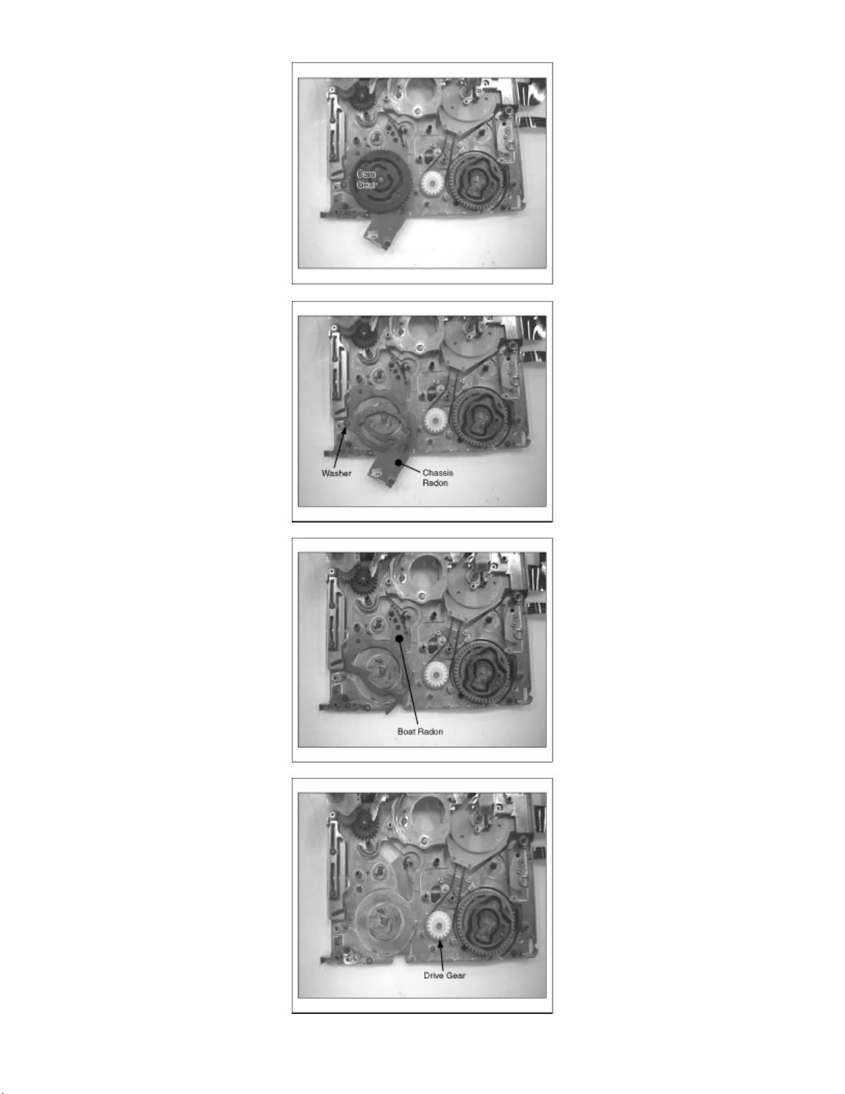
Fig. D14
Fig. D15
Fig. D16
Fig. D17-1
Page 17

Fig. D17-2
Fig. D18-1
Fig. D18-2
Page 18

Fig. D19
Fig. D20-1
Fig. D20-2
Page 19

Fig. D20-3
Fig. D21
Page 20

4 ASSEMBLY PROCEDURE
4.1 ASSEMBLY PROCEDURE
No. Item Fig. Grease Procedure
*1 S3 Base U. Fig. A1 -- 1) Put S3 Base U on and tighten a screw.
*2 T4 Guide , Eject Lever, Pulley Cover
& Pulley.
*3 Mode Switch , Deceleration Gears &
Tension Plate.
Interface Flex.
5 Capstan Holder & Capstan Motor
6 Drive Gear Fig. A6 -- 1) Put a washer to shaft and install Drive Gear.
7 Boat Radon Fig. A7 • 1) Put hole of Boat radon to shaft of chassis.
8 Chassis Radon Fig. A8 • 1) Put Chassis Radon and a washer on.
9 Cam Gear Fig. A9 • 1) Put Cam Gear on. Phase Mark should be in the same line with chassis of
10 Interface Gears
11 Tension Lever & Eject Arm. Fig.
12 Pinch Beetle & Release Beetle Fig.
15 Rail Unit
Fig.
A2-1
Fig.
A2-2
Fig.
A2-3
Fig.
A2-4
Fig. A3
Fig. A4
Fig.
A5-1
Fig.
A5-2
Fig.
A10-1
Fig.
A10-2
A11
A12
A13
A14
Fig.
A15-1
Fig.
A15-2
Fig.
A15-3
• 1) Put hole of T4 Guide to hole of chassis and tighten a screw.
• 2) Put Eject Lever on and a washer.
-- 3) Put boss of Pulley to hole of chassis on. Hole of chassis under pulley should
be visible through slit of Pulley.
-- 4) Put Pulley Cover on Pulley and tighten 2 screws.
• 1) Put Mode Sw on.
• 2) Put Deceleration Gear (B) on
• 3) Put Deceleration Gear (A) on and a washer.
• 4) Put Tension Plate on and 2 washers.
-- 1) Put Loading Motor Unit on and tighten 2 screws. 4 Loading Motor unit & Mechanism
-- 2) Put Mechanism Interface Flex on and tighten 4 screws. After that, solder at
terminal of Mode Sw.
-- 1) Put Capstan Motor on and tighten 3 screws.
Timing Belt should be between Pulley and boss.
-- 2) Put Capstan Holder on and tighten 2 screws.
Timing Belt should be wound around Drive Gear. After that, confirm Timing
Belt and Gear are rotated together.
shaft..
• 1) Put Interface Gear(C) & (D).
Each phase mark should be in the same line.
• 2) Put Interface Gear(A) & (B) on.
1) Put boss of Tension Lever into slit of Cam Gear and Tension Plate, then
--
tighten a screw.
2) Put boss of Eject Arm into slit of Cam Gear.
Put a washer on shaft of chassis.
1) Put boss of Pinch Beetle into slit of Mode Sw.
•
2) Put boss of Release Beetle into slit of Mode Sw.
3) Put a washer on.
1) Keep sliding Gear Cover and put it on. 13 Gear Cover Fig.
--
2) Tighten a screw.
1) Put S-Loading Gear on. 14 T-Loading Gear & S-Loading Gear Fig.
•
2) Put T-Loading Gear on.
Each phase mark should be in the same line.
1) Make half loading until Connection Arm comes out.
--
2) Connect Arm of S & T Loading Gear and Connection Arms.
-a) Hold Loading Gear side.
b) Push Arm of S & Tloading Gear into slit of connection arms.
--
3) Tighten 4 screws.
Page 21

16 Pinch Arm & Center Gear
17 Sub Chassis Unit
18 LED Holder, Cover plate & Idler U.
19 Confirmation of Mechanism
movement , Cylinder Unit & RT Flex.
Flame.
*20 H Amp Unit.
(Only Q1 & Q2)
Fig.
A16-1
Fig.
A16-2
Fig.
A17-1
Fig.
A17-2
Fig.
A17-3
Fig.
A17-4
Fig.
A18-1
Fig.
A18-2
Fig.
A18-3
Fig.
A19-1
Fig.
A19-2
FIg.
A19-3
Fig.
A20-1
Fig.
A20-2
Fig.
A20-3
Fig.
A21-1
Fig.
A21-2
--
1) Put Center Gear Spacer on shaft of chassis.
2) Put Center Gear on.
• 3) Make full loading position and put Pinch arm on, then put a washer on.
1) Make unloading position until moving Release Beetle
-Confirm spring is exist.
2) Put Sub Chassis Unit on as pre-installation.
3) Tighten 3 screws.
Make Loading position until 1 screw position appears, then tighten a screw.
4) Tighten a screws at Flex Holder portion and Hook spring back to Pinch Arm.
-- 1) Put Idler U into shaft of Drive Gear.
2) Put Cover Plate on and tighten 5 screws, then hook 2 springs to 2hooking
-portion of Sub chassis.
And also put LED Flat Cable back.
3) Put LED Holder back.
-- 1) Confirm loading and unloading is smooth.
-- 2) Put Cylinder Unit & Spring on and tighten 3 screws.
-- 3) Put RT Flex. Flame on and tighten 2 screws.
1) Put H Amp Unit on and tighten a screw at bottom of chassis.
--
2) Connect Cylinder Flex to connector.
3) Put Shield case on and tighten a screw.
1) Put both S &T sides to coupling portion on. 21 Cassette Up Unit.
--
2) Tighten 3 screws. (Q1 &2 have 4 screws)* 1)
Procedure 20 for H.Amp Unit is applied only Q1 & Q2
mechanism.
2) Procedure 1 - 3 can be changed in order.
The following parts should be applied Molyton Grease (VFK1024).
Page 22

How to use washer jigs.
No. Item Fig. Procedure
1 Fig. W1-1 1) Each Washers.
2 Fig. W1-2 1) Put a washer on tip of Jig.
3 Fig. W1-3 1) Put Jig on shaft.
4
Washer Jigs
Fig. W1-4
1) Put a washer on shaft by pressing Jig.
Fig. W1-1
Fig. W1-2
Page 23

Fig. W1-3
Fig. W1-4
Fig. A1
Page 24

Fig. A2-1
Fig. A2-2
Fig. A2-3
Page 25

Fig. A2-4
Fig. A3
Fig. A4
Page 26

Fig. A5-1
Fig. A5-2
Page 27

Fig. A6
Fig. A7
Fig. A8
Page 28

Fig. A9
Fig. A10-1
Fig. A10-2
Page 29

Fig. A11
Fig. A12
Fig. A13
Page 30

Fig. A14
Fig. A15-1
Fig. A15-2
Page 31

Fig. A15-3
Fig. A16-1
Fig. A16-2
Page 32

Fig. A17-1
Fig. A17-2
Fig. A17-3
Page 33

Fig. A17-4
Fig. A18-1
Fig. A18-2
Page 34

Fig. A18-3
Fig. A19-1
Fig. A19-2
Page 35

FIg. A19-3
Fig. A20-1
Fig. A20-2
Page 36

Fig. A20-3
Fig. A21-1
Fig. A21-2
Page 37

5 MECHANICAL ADJUSTMENT PROCEDURE
5.1 MECHANICAL ADJUST TABLE
No. Item Confirmation of
1 MECHANISM
CHASSIS
2 Cassette Up Unit. -- -- -- -- -- --
*3 H Amp Unit. -- -- • -- -- --
4 Cylinder Unit • • • -- -- -5 RT Flex. Flame. -- -- -- -- -- -6 LED Holder -- -- -- -- -- -7 Cover Plate -- -- -- -- -- -8 Idler U. -- -- • -- -- --
9 Sub Chassis Unit • • • -- -- •
10 Pinch Arm • • • -- -- -11 Center Gear -- -- • -- -- -12 Rail Unit • • • -- -- -13 S-Loading Gear -- -- • -- -- -14 T-Loading Gear -- -- • -- -- -15 Gear Cover -- -- • -- -- -16 Pinch Beetle -- -- • -- -- -17 Release Beetle -- -- • -- -- -18 Tension Lever • • • -- -- -19 Eject Arm -- -- -- -- -- -20 Interface Gears -- -- • -- -- -21 Cam Gear -- -- • -- -- -22 Chassis Radon -- -- -- -- -- -23 Boat Radon -- -- -- -- -- -24 Drive Gear -- -- • -- -- -25 Capstan Holder -- -- -- -- -- -26 Capstan Motor • • • • -- -27 Loading Motor
Unit
28 Mechanism
Interface Flex.
29 Mode Switch -- -- -- -- -- -30 Deceleration
Gears
31 Tension Plate • • • -- -- -32 T4 Guide -- -- -- -- -- -33 Eject Lever -- -- -- -- -- -34 Pulley Cover -- -- -- -- -- -35 Pulley -- -- -- -- -- -36 S3 Base U. • • • -- •
Tape Running
-- -- • -- -- --
-- -- -- -- -- --
-- -- -- -- -- --
-- -- • -- -- --
Linearity
Adjustment
Confirmation of
B.E.R. Value
Capstan tilt
Adjustment
S3 Base
adjustment
Sub Chassis Adjustment
--* 1) H.Amp Unit is
applied only Q1 &
Q2 mechanism.
Page 38

5.2 MECHANICAL ADJUSTMENT PROCEDURE
No. Item Equipment Fig. Procedure
Running
2 Linearity Adjustment
3 Confirmation of
B.E.R. Value
4 Capstan tilt
Adjustment
6 Sub Chassis
Adjustment
1. Alignment Tape
(PAL: VFM3110EDS/NTSC:
VFM3010EDS)
2. Post Adjustment
Driver(VFK1278)
1.Tatsujin system(Refer to Fig.) Fig.
2. Alignment Tape
(PAL: VFM3110EDS/NTSC:
VFM3010EDS)
3. Envelope Detecor Board
(VFK1641)
4. Post Adjustment Driver
(VFK1278)
1.Tatsujin system(Refer to Fig.) Fig.
1. Capstan Tilt Adj. Jig(VFK1638)
2. Small Phillips Screw Driver
Driver(VFK1278)
1. Small Phillips Screw Driver
Fig.
AD1-1
Fig.
AD1-2
AD2-1
Fig.
AD2-2
-- 3) Remove Adjustment Cover.
Fig.
AD2-3
AD2-1
Fig.
AD4-1
Fig.
AD4-2
Fig.
AD5-1
Fig.
AD5-2
Fig.
AD6-1
Fig.
AD6-2
Fig. AD1-1
1) Confirm each post position in playback mode. 1 Confirmation of Tape
2) Confirm condition of tape regulation in playback & review
mode.
1) Set up Tatsujin System.
2) Connect Envelope Detector Board between Measuring Board &
Oscilloscope.
* Location for Adjustment Cover depends on Models.
4) Playback the Alignment Tape and adjust S2 & T3 posts by
Screw Driver until wavefom becomes flat.
After adjustment, B.E.R. should be confirmed by Electrial
adjustment on the "Tatsujin".
1) Refer to Electrical Adjustment on the "Tatsujin".
1) Slide sensor pin to Capstan shaft.
After touching,if OK, LED should be lit.
* Do not touch when you confirm LED lit or not.
2) If Ng, Capstan tilt should be adjusted.
a) Tighten screw (A) until LED is lit.
b) Loose screw (B) until LED is not lit.
c)Tightenscrew (A) unti-clockwise until LED is lit .
1) Adjust S3 screw as Evvelope becomes flat. 5 S3 Base adjustment 1. Post Adjustment
2) Tighten a screw 180 degree as "ENV 1".
3) Loosen a screw as ENV 2.
4) Tighten a screw until ENV becomes flat as ENV 3 and tighten
a screw 180 degree again.
1) Make Review Position.
* Set Loading mode and then,stop Pinch Roller & Capstan shaft is
touched.
2) Loosen a screw.
After fixing a shaky Sub Chassis,then tighten a screw.
Fig. AD1-2
Page 39

Fig. AD2-1
Fig. AD2-2
Fig. AD2-3
Fig. AD4-1
Fig. AD4-2
Page 40

Fig. AD5-1
Fig. AD5-2
Fig. AD6-1
Page 41

Fig. AD6-2
Page 42

6 EXPLODED VIEWS
6.1 Q1& Q2 VCR MECHANISM SECTON (1)
Page 43

6.2 Q1& Q2 VCR MECHANISM SECTION (2)
Page 44

6.3 Q3 VCR MECHANISM SECTION (1)
Page 45

6.4 Q3 VCR MECHANISM SECTION (2)
Page 46

7 REPLACEMENT PARTS LIST
7.1 Q1& Q2 VCR MECHANISM SECTION (1) PARTS LIST
Ref. No. Part No. Part Name & Description Remarks
601 VEG1495 CYLINDER U.
602 DFX25A7VWB CAPSTAN U.
603 VDG1284 DRIVE GEAR
604 VDG1285 CENTER GEAR
605 VDG1290 INTERFACE GEAR (C)
606 VDG1291 INTERFACE GEAR (D)
607 VDG1295 DECELERATION (A) NV-EX1,NV-DS77
607 VDG1330 DECELERATION (A) NV-DS99/990,NV-DS33,NV-EX3
608 VDG1296 DECELERATION (B) NV-EX1,NV-DS77
608 VDG1331 DECELERATION (B) NV-DS99/990,NV-DS33,NV-EX3
609 VDG1297 INTERFACE GEAR (A)
610 VDG1303-A INTERFACE GEAR (B)
612 VMA9908 PULLEY COVER
613 VMA9916 T4 GUIDE
614 VMA9917 TENSION PLATE
615 VMA0E52 GEAR COVER
616 VHD1430 CAPSTAN HOLDER NV-EX3
617 VMC1443 CYLINDER SPRING
618 L6DA8DKC0001 LOADING MOTOR U. NV-EX1,NV-DS77
619 VEM0679 LOADING MOTOR U. NV-DS99/990,NV-DS33,NV-EX3
620 VWJ1297 MECHANISM INTERFACE FLEX. NV-DS99/990,NV-DS33,NV-EX3
622 K0ZZ00000453 MODE SWITCH
623 VXA6124 S LOAD GEAR U.
624 VXA6125 T LOAD GEAR U.
625 VXA6133 PULLEY COVER
626 VXA6134 CHASSIS RADON U.
627 VXA6135 CAM GEAR U.
628 VXA6136 PINCH BEETLE
629 VXA6137 RELEASE BEETLE
630 VXA6138 RAIL U.
631 VXA6169 BOAT RADON U.
632 VXA6184 S3 BASE U.
Page 47

633 VXL2814 EJECT LEVER U.
634 VXL2815 TENSION LEVER U.
635 VXL2816 EJECT ARM U.
636 VXL2897 PINCH ARM U.
637 VXL2818 IDLER U.
638 VYK8485 HEAD AMP U. NV-EX1
638 VYK8244 HEAD AMP U. NV-DS77
638 VYK8886 HEAD AMP U. NV-DS99/990,NV-DS33
638 VYK9102 HEAD AMP U. NV-EX3
621 VSC4802 SHIELD CASE NV-EX1
621 VSC4758 SHIELD CASE NV-DS77,NV-DS99/990,NV-DS33
639 VMA9926 CAPSTAN HOLDER NV-EX1,NV-DS77,NV-DS99/990,NV-DS33
B601 VHD1155 SCREW
B602 VHD1372 SCREW
B603 VHD1372 SCREW
B604 VHD1372 SCREW
B606 VHD1160 SCREW
B608 VHD1160 SCREW
B609 VHD1406 SCREW
B610 VHD1161 SCREW
B611 VHD1161 SCREW
B612 VHD1161 SCREW
B613 VHD1161 SCREW
B614 VHD1161 SCREW
B615 VHD1162 SCREW
B616 VHD1162 SCREW
B619 VHD1163 SCREW
B621 XQN12+B14FN SCREW
B622 XQN12+A1 SCREW
B623 XQN12+A1 SCREW
B624 XQN12+A1 SCREW
B625 XQN12+A1 SCREW
B626 XQN12+A1 SCREW
B627 XQN12+A12FN SCREW
B628 XQN12+A12FN SCREW
B631 XQN12+B2 SCREW
Q1/2/3 MECHANISM
Page 48

B632 VHD1162 SCREW NV-EX1,NV-DS77,NV-DS99/990,NV-DS33
B633 VHD1162 SCREW NV-EX1,NV-DS77,NV-DS99/990,NV-DS33
B634 XQN16+B12 SCREW NV-EX1,NV-DS77,NV-DS99/990,NV-DS33
N601 VHN0324 NUT
W601 VMX2028 WASHER
W602 VMX2751 WASHER
W603 VMX2752 WASHER
W604 VMX2392 WASHER
W605 VMX2028 WASHER
W606 VMX2028 WASHER
W607 VMX2028 WASHER
W608 VMX2028 WASHER
W609 VMX2028 WASHER
W610 VMX2028 WASHER
W611 VMX2028 WASHER
7.2 Q1& Q2 VCR MECHANISM SECTION (2)
PARTS LIST
Ref. No. Part No. Part Name & Description Remarks
651 VMD2975 LED HOLDER
652 VXA7407 SUB SHASSIS U. Q1/2/3 MECHANISM NV-DS99/990,NV-DS33,NV-EX3
652 VXA6146 SUB SHASSIS U. NV-EX1,NV-DS77
653 VXA6151 COVER PLATE U.
654 VXA7408 CASSETTE UP U. Q1/2/3 MECHANISM
B651 VHD1162 SCREW
B652 VHD1162 SCREW
B653 VHD1162 SCREW
B654 VHD1162 SCREW
B655 VHD1207 SCREW
B656 VHD1164 SCREW
B657 VHD1164 SCREW
B658 VHD1171 SCREW
Page 49

B659 VHD1314 SCREW
B660 VHD1314 SCREW
B661 VHD1163 SCREW
B662 VHD1163 SCREW
7.3 Q3 VCR MECHANISM SECTION (1)
PARTS LIST
Ref. No. Part No. Part Name & Description Remarks
501 VEG1620 CYLINDER U. NV-EX21,NV-DS68/88/89/25/12/15/150,NV-MX2/8/300/1/3/5/7
501 VEG1619 CYLINDER U. NV-GS1/3/4/5,NV-GX7
501 VEG1495 CYLINDER U. NV-DS35/55
502 DFX25A7VWC CAPSTAN U. NV-EX21,NV-DS68/88/89/25/12/15/150,NV-MX2/8/300/1/3/5/7
502 DFX25A7VWB CAPSTAN U. NV-DS35/55
503 VDG1284 DRIVE GEAR
504 VDG1285 CENTER GEAR
505 VDG1290 INTERFACE GEAR (C)
506 VDG1291 INTERFACE GEAR (D)
507 VDG1330 DECELERATION GEAR (A)
508 VDG1331 DECELERATION GEAR (B)
509 VDG1297 INTERFACE GEAR (A)
510 VDG1303 INTERFACE GEAR (B)
512 VMA9908 PULLEY COVER
513 VMA9916 T4 GUIDE
514 VMA9917 TENSION PLATE
515 VMA0E52 GEAR COVER
516 VHD1430 CAPSTAN HOLDER
517 VMC1443 CYLINDER SPRING
519 VEM0679 LOADING MOTOR U.
520 VWJ1297 MECHANISM INTERFACE FLEX.
521 VMP6271 RT FLEX. FRAME NV-EX21,NV-DS68/88/89/25/12/15/150,NV-MX2/8/300/1/3/5/7
522 K0ZZ00000453 MODE SWITCH
523 VXA6124 S LOAD GEAR U.
524 VXA6125 T LOAD GEAR U.
525 VXA6133 PULLEY
526 VXA6169 BOAT RADON U. Q3 MECHANISM
527 VXA6135 CAM GEAR U.
Page 50

528 VXA6136 PINCH BEETLE
529 VXA6137 RELEASE BEETLE
530 VXA6138 RAIL U.
531 VXA6134 CHASSIS RADON U. Q3 MECHANISM
532 VXA6184 S3 BASE U.
533 VXL2814 EJECT LEVER U.
534 VXL2815 TENSION LEVER U.
535 VXL2816 EJECT ARM U.
536 VXL2897 PINCH ARM U.
537 VXL2818 IDLER U.
538 VYK8886 HEAD AMP U. NV-DS35/55
B501 VHD1155 SCREW
B502 VHD1372 SCREW
B503 VHD1372 SCREW
B504 VHD1372 SCREW
B505 XQN14+B1FN SCREW NV-EX21,NV-DS68/88/89/25/12/15/150,NV-MX2/8/300/1/3/5/7
B506 VHD1160 SCREW
B508 VHD1160 SCREW
B509 VHD1406 SCREW
B510 VHD1161 SCREW
B511 VHD1161 SCREW
B512 VHD1161 SCREW
B513 VHD1161 SCREW
B514 VHD1161 SCREW
B515 VHD1162 SCREW
B516 VHD1162 SCREW
B519 VHD1163 SCREW
B521 XQN12+B14FN SCREW Q1/2/3 MECHANISM
B522 XQN12+A1 SCREW
B523 XQN12+A1 SCREW
B524 XQN12+A1 SCREW
B525 XQN12+A1 SCREW
B526 XQN12+A1 SCREW
B527 XQN12+A12FN SCREW
B528 XQN12+A12FN SCREW
Page 51

B530 XQN16+B2 SCREW
B535 XQN16+B3 SCREW NV-DS35/55
N501 VHN0324 NUT
W501 VMX2028 WASHER
W502 VMX2028 WASHER
W503 VMX2028 WASHER
W504 VMX2028 WASHER
W505 VMX2028 WASHER
W506 VMX2028 WASHER
W507 VMX2028 WASHER
W508 VMX2751 WASHER
W509 VMX2752 WASHER
W510 VMX2392 WASHER
W511 VMX2028 WASHER
7.4 Q3 VCR MECHANISM SECTION (2)
PARTS LIST
Ref. No. Part No. Part Name & Description Remarks
551 VMD2975 LED HOLDER
552 VXA7407 SUB CHASSIS U. Q1/2/3 MECHANISM
553 VXA6151 COVER PLATE U.
554 VXA7408 CASSETTE UP U. Q1/2/3 MECHANISM
B551 VHD1162 SCREW
B552 VHD1162 SCREW
B553 VHD1162 SCREW
B554 VHD1162 SCREW
B555 VHD1207 SCREW
B556 VHD1164 SCREW
B557 VHD1164 SCREW
B558 VHD1171 SCREW
B559 VHD1314 SCREW
B560 VHD1314 SCREW
B561 VHD1163 SCREW
B562 VHD1163 SCREW
 Loading...