

Page 1

Gooseneck Wall Mount
PWM20G Videolarm for Panasonic
1
DESCRIPTION
With its distinctive gooseneck design, the PWM20G presents a sleek,
aesthetically pleasing look. This wall mount will supports most
VIDEOLARM outdoor domes, as well as those of many other manufacturers.
FEA TURES:
• Durable powder coat finish
• All aluminum construction
• 1 1/2” pipe thread on end for quick and easy dome mounting
• 75 lb load rating
Outdoor Dome Brackets and Mounts
2.50
4.95R
11.88
.250" plot hole,
for conduit
10.89
135˚
TYP. 4 PLCS
1.38
2.19
.50Ø
.75
7.00
5.50
2.00
3.25
24-hour technical assistance
1-800-554-1124
2525 Park Central Blvd.
26
Decatur, GA 30035
Phone: (770) 987-7550
1-800-554-1124
U.S. & Canada only
Model Unit Shipping Shipping
Weight Weight Box Dim.
PWM20G250 lbs250 lb15’ x 12” x 12”
* Shipping weights depend on box dimensions.
Spec# Rev. Date Catalog Section VidFax#
6024 0195 1 S24
Due to our continued efforts to advance technology, product specifications
are subject to change without notice.
Fax: (770) 987-9705
1-800-826-0366
VidFax: 1-800-547-5044
Email: info@videolarm.com
www.videolarm.com
Page 2
Manufactured by:
Before attempting to connect or operate this product, please read these instructions completely.
MODEL: PWM20G
STANDARD INSTALLATION PROCEDURE
INCLUDES MODEL: PWM20G
1. Choose an appropriate location on an outside wall to
mount the PWM20G.
NOTE: Be sure that the wall is sturdy enought to support
the combined weight of the bracket and housing.
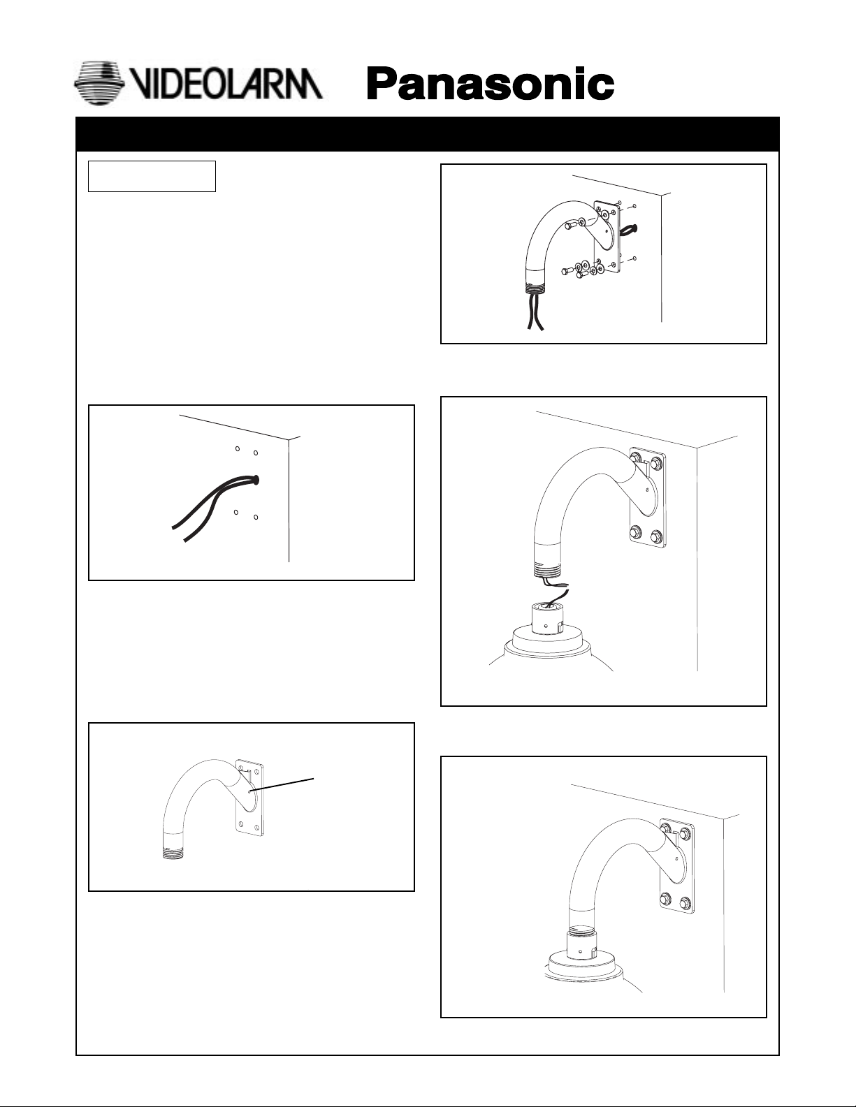
2. Place the base against the wall, mark the location of
the four mounting holes, remove the bracket and drill the
mounting holes. Pull all wiring through the wall at this
time (Figure 1).
81-IN3058-9922
PRODUCT INSTRUCTIONS
Figure 3
5. Make all wiring connections to the housing, following
instructions provided with the housing (Figure 4).
Figure 1
3. Run wiring into and through the PWM20G bracket. Make
sure you also have enough to run into the housing for
connections.
NOTE: For applications where the wiring cannot be pulled
through the wall, a starter hole is provided on the
side of the bracket near the base. Use this to drill
a larger hole to pass conduit into and through the
bracket (Figure 2).
Starter Hole
Figure 2
4. Mount the PWM20G to the wall (hardware not included).
(Figure 3)
Figure 4
5. Screw the housing coupling onto the PWM20G 1 1/2" pipe
thread (Figure 5). Make sure all attachments are secure.
Figure 5
Page 3

1. Read Instructions - All the safety and operating instructions
!
should be read before the unit is operated.
2. Retain Instructions - The safety and operating instructions
should be retained for future reference.
3. Heed Warnings - All warnings on the unit and in the operating
instructions should be adhered to.
4. Follow Instructions - All operating and user instructions should
be followed.
5. Electrical Connections - Only a qualified electrician should
make electrical connections.
6. Attachments - Do not use attachments not recommended by the
product manufacturer as they may cause hazards.
7. Cable Runs - All cable runs must be within permissible distance.
8. Mounting - This unit must be properly and securely mounted to
a supporting structure capable of sustaining the weight of the
unit. Accordingly:
a. The installation should be made by a qualified service
person, and should conform to all local codes.
b. Care should be exercised to select suitable hardware to
install the unit, taking into account both the composition of the
mounting surface and the weight of the unit. Be sure to
periodically examine the unit and the supporting structure to
make sure that the integrity of the installation is intact. Failure
to comply with the foregoing could result in the unit separating
from the support structure and falling, with resultant damages
or injury to anyone or anything struck by the falling unit.
SAFETY PRECAUTIONSIMPORTANT SAFEGUARDS
CAUTION
RISK OF
ELECTRIC SHOCK!
CAUTION: TO REDUCE THE RISK OF
ELECTRICAL SHOCK, DO NOT EXPOSE
COMPONENTS TO WATER OR MOISTURE.
The lightning flash with an arrowhead symbol,
within an equilateral triangle, is intended to
alert the user to the presence of non-insulated
"dangerous voltage" within the product's
enclosure that may be of sufficient magnitude
to constitute a risk of electric shock to persons.
The exclamation point within an equilateral
triangle is intended to alert the user to
!
UNPACKING
Unpack carefully. Electronic components can be
damaged if improperly handled or dropped. If an item
appears to have been damaged in shipment, replace it
properly in its carton and notify the shipper.
presence of important operating and
maintenance (servicing) instructions in the
literature accompanying the appliance.
Be sure to save:
1. The shipping carton and packaging material. They are the
safest material in which to make future shipments of the
equipment.
2. These Installation and Operating Instructions.
SERVICE
For service on Panasonic/Videolarm equipment contact:
Panasonic Technical Center
54 West Gude Dr.
Rockville MD 20850-1150
Phone: 301-762-5125
Fax: 301-251-0347
PANASONIC TECHNICAL SUPPORT
1-800-528-6747
9:00 AM - 5:00 PM EASTERN TIME
- 2 -
 Loading...