

Page 1
Thank you for choosing
Panasonic
OmnlvlBicxi
Video Cassette Recorder
Era
3 O
‘Û 7
Q> -L
3. 00
0)
a
Operating
Instructions
Easy loping.
As an Energy Star* Paitncr. Matsushiia Electric
CoqxM^on of America has detemüncd that this
product or product model meets the
guidelines f(x energy efficiency.
Please read these instructions carefully before attempting to
connect, operate or adjust this product. Please save this manual.
Spanish Quick Use Guide is included. (Quia para rápida consulta en espafSol está incluida.)
Quick Use Guide is on the back cover.
VQTS3475 (A)
Energy Star*
Page 2
Things You Should Know
Congratulations
on your purchase of one of the most sophisticated and
reliable products on the market today. Used properly, it
will bring you and your family years of enjoyment.
Please fill in the information at right. The serial number
is on the tag located on the back of your VCR.
f Date of Purchase.
Dealer Purchased From.
Dealer Address
Dealer Phone No
Model No
Serial No
________
____________
_________
___________________
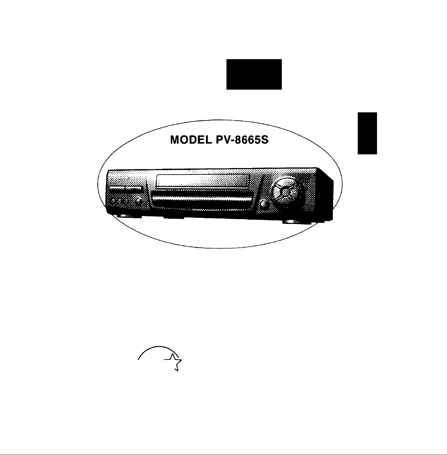
PV=a665S
Safety Precautions
Warning: To prevent fire or shock hazard, do not expose this equipment to rain or moisture.
This video recorder, equipped with the HQ (High Quality) System, is compatible with existing VHS equipment.
Qnly use those tapes with the iVHSl mark. It is recommended that only cassette tapes that have been tested
and inspected for use in 2,4, 6, and 8 hour VCR machines be used.
FCC Warning: Any unauthorized changes or modifications to this equipment would void the user's authority to operate.
This symbol warns the user that uninsulated voltage within the unit may
A
CAimOM TO RCOUC£ THE RBK OF CLECmiC SHOCK,
DO l«OT REMOVE COVER (OR BACK)
HOUSER-SERVICEASLE parts #«soe
REFER SERVCRIQ TO CXJAUFED SERVCE PERSONNEL
Important Safeguards and Precautions........................................................................................................... 3
Unpacking Your VCR • Product Features........................................................................................................ 4
VCR and Cassette Information {Record Tab, Tape speeds, Head Cleaning, DST., Specifications)
A
have sufficient magnitude to cause electric shock. Therefore, it is dangerous
to make any kind of contact with any inside part of this unit.
This symbol alerts the user that important literature concerning the operation
and maintenance of this unit has been included. Therefore, it should be read
carefully in order to avoid any problems.
..........
5
Basic Connection (Antenna and VCR, VCR and TV).................................................................................. 6, 7
Other Connections (cable, AudioA/ideo)...................................................................................................... 8, 9
Location of Controls (Remote Control, VCR) ........................................................................................ 10,11
One Time VCR Setup (On-Screen Language, Cable Box/DSS Receiver Setup, Channel Memory, Auto Clock Set) . 12-17
On-Screen Displays (OSD) (Function, Channel, Menu, VCR Status & Clock, Warning)
Playback a Tape (Main operation, Special Effects, Quality Picture Features)........................................... 19
Record On a Tape (Main Operation, One Touch Record, Select Input Mode, Channel Selection)
Timer Recording (Main Operation, Cancel, Clear or Replace Program Contents).............................. 22, 23
Tape Operation (index Search, Repeat Play, One Minute Skip, Zero Search, Auto Functions)
Special VCR Features (VCR Lock, Warning Beeper, Channel Caption, Time Stamp, Blue Back ON/OFF) .. 27-30
Copying Your Tapes (Dubbing) (Connection, Main operation, Monitoring)
MTS Broadcast/ VHS Hi-Fi Stereo System (Stereo/SAP/Mono Broadcast, Select Audio Mode)
VCR Plus+ Setup (VCR Plus+ channel Setup).............................................................................................. 34
VCR Plus+ Programming (Main operation, Make Correction)..................................................................... 35
Multi-Brand Control Feature.................................................................................................................... 36, 37
Before Requesting Service (Seif-check items).............................................................................................. 38
Warranty............................................................................................................................................................. 39
Spanish Quick Use Guide......................................................................................................................... 40 -43
Quick Use Guide................................................................................................................................Back Cover
..............................................
...........................
...
20, 21
.....
24-26
.......
32, 33
18
31
Page 3

Im po rt an t S af eg ua rd s an d Pr ec au ti on s
FOR YOUR SAFETY, READ AND
RETAIN ALL SAFETY AND OPERATING
INSTRUCTIONS. HEED ALL WARNINGS
IN THE MANUAL AND ON THE UNIT
INSTALLATION
1 POWER SOURCE CAUTION
Operate only from a power source indicated on the
unit or in this manual, if necessary, have your Eiectric
Utility Service Company or Video Products Dealer verify
the power source in your home.
2 POLARIZED OR GROUNDING PLUG
As a safety feature, this Video product comes witii either
a polarized power cord plug (one blade is wider than the
other), or a three-wire grounding type plug.
POLARIZED PLUG CAUTION:
This plug will only fit into an outiet one way. If you cannot
fully insert the plug, try reversing it. If it still will not fit, have
an electrician install the proper wall outlet. Do not defeat the
safety feature by tampering wifti the plug.
GROUNDING PLUG CAUTION:
This plug will only fit into a Uiree-hole grounding outlet. If
necessary, have an electrician install the proper outlet. Do
not defeat the safety feature by tampering with the plug.
3 POWER CORO
Make sure power cords are routed so that they are not
likely to have anything rest on them, roll over them, or be
in the way of walking traffic.
If an extension cord is used, make sure it also has either
a polarized or grounded plug and that the cords can be
securely connected.
Frayed cords, damaged plugs, and damaged or cracked
wire insulation are hazardous and should be replaced by
a qualified service technician.
Overloaded outlets and extension cords are fire hazards
and should be avoided.
4 DO NOT BLOCK VENTILATION HOLES
Ventilation openings in the cabinet release heat
generated during operation. If they are blocked, heat
build-up inside the unit can cause failures that may result
in a fire hazard or heat damage to cassettes.
For protection, follow these rules:
, a. Never cover ventilation slots or the unit while in use,
or operate the unit when placed on a bed, sofa, rug,
or other soft surface.
b. Avoid built-in installation, such as a book case or
rack, unless proper ventilation is provided.
5 AVOID EXTREMELY HOT LOCATIONS OR SUDDEN
TEMPERATURE CHANGES
Do not place the unit over or near any kind of heater or
regulator, in direct sunlight, inside a closed vehicle, etc..
Do not move the unit suddenly between areas of
extreme temperature variation. If the unit is suddenly
moved from a cold place to a warm place, moisture
may condense in the unit and on the tape.
6 TO AVOID PERSONAL INJURY
• Do not place unsecured equipment on a sloping
surface.
• Do not place this unit on any support
that is not firm, level, and adequately
strong. The unit could fall causing
serious injury to a child or adult and
damage to the unit.
• An appliance and cart combination
should be moved with care.
Quick stops, excessive force, and
uneven surfaces may cause the
appliance and cart combination to overturn.
• Carefully follow all operating instructions and use
the manufacturer's recommended accessories
when operating this unit or connecting it to any
other equipment.
OUTDOOR ANTENNA INSTALLATION
SAFE ANTENNA AND CABLE CONNECTION
If an outside antenna or cable system
is connected to the equipment,
be sure the antenna or cable system
is grounded so as to provide some
protection against built up static
charges and voltage surges.
Section 810 of the National
Electrical Code, ANSI/NFPA 70
(in Canada, part 1 of the Canadian
Electrical Code) provides information
with respect to pr^er grounding of the
mast and supporting structure, grounding
of the lead-in wire to an antenna discharge unit,
size of grounding conductors, location of antenna discharge unit, connection
to grounding electrodes and requirements for the grounding electrode.
KEEP ANTENNA CLEAR OF HIGH VOLTAGE POWER LINES
OR CIRCUITS
An outside antenna system should be located well away from power lines,
electric light or power circuits and where It will never come into contact with
these power sources if it should happen to fall. When installing an outside
antenna, extreme care should be taken to avoid touching power lines,
circuits or other power sources as this could be fatal. Because of the
hazards involved, antenna installation should be left to a professional.
USING THE VIDEO UNIT
If the unit has been in storage or moved to a new location,
refer first to the INSTALLATION section of these safeguards.
1 KEEP THIS VIDEO UNIT AWAY FROM WATER OR
MOISTURE OF ANY KIND.
2 IF EQUIPMENT IS EXPOSED TO RAIN, MOISTURE, OR
STRONG IMPACT, unplug the unit and have it inspected by a qualified
service technician before use.
3 DURING AN ELECTRICAL STORM
During a lightning storm, whether indoors or outdoors, or before leawng the
unit unused for extended periods of time, disconnect alt equipment from the
power source as well as the antenna and cable system.
4 WHEN THE UNIT IS PLUGGED IN
• Never expose the unit to rain or water. DO NOT OPERATE if liquid has
been spilled into the unit. Immediately unplug the unit, and have it
inspected by a service technician. Fire and shock hazards can result from
electrical shorts caused by liquid contact inside.
• Never drop or push any object through openings in the unit. Some interrral
parts carry hazardous voltages and contact can cause electric shock or
fire hazard.
• Avoid placing the unit directly above or below your TV set as this may
cause electrical interference. Keep all magnets away from electronic
equipment.
5 USING ACCESSORIES
Use only accessories recommended by the manufacturer to avoid risk of
fire, shock, or other hazards.
6 CLEANING THE UNIT
Unplug the unit. Then, use a clean, dry, chemically untreated cloth to gently
remove dust or debris. DO NOT USE cleaning fluids, aerosols, or forced air
that could over-spray, or seep into the unit and cause electrical shock.
Any substance such as wax, adhesive tape, etc. may rrrar the cabinet
surface. Exposure to greasy, humid, or dusty areas may adversely affect
internal parts.
SERVICE
DO NOT SERVICE THIS PRODUCT YOURSELF
If, after carefully following the detailed operating instructions, this Video
product does not operate property, do rwt attempt to open or remove covers,
or make any adjustments not described in the manual. Unplug the unit and
contact a qualified service technician.
IF REPLACEMENT PARTS ARE REQUIRED
Make sure №e service technician uses only parts specified by the manufacturer,
or those having the same safety characteristics as the original parts. The use of
unauthorized substitutes may result in fire, electric shock, or other hazards.
HAVE THE SERVICE TECHNICIAN PERFORM
A SAFETY CHECK
After any service or repairs to the unit, request the service technician to
conduct a thorough safety check as described in the manufacture’s service
literature to insure that the video unit is in safe operating condition.
Page 4
UnpackingJ^ourVC^^JPr^^
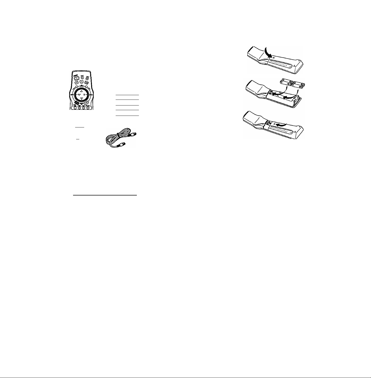
Unpacking Your VCR
The accessories below are provided to help
you use or set up your VCR.
Accessories
Light Tower^'^ Universal
Remote Control
VSQS1578
)
)
4“AA"
)
O 0©
O O ©
© © ©
8 03'
o S CH
o o Qj
elo
To order accessories,
call toll free 1-800-211-PANA (7262).
Batteries
)
RF Coaxial
Cable
VJAS0196
Loading the Batteries
1 Press down on the in»-
mark and slide the Battery
Compartment lid open.
Install four batteries as
indicated inside the
Battery Compartment.
Slide the Battery
Compartment
lid back into place.
Battery replacement caution
• Do not mix old and new batteries.
• Do not mix alkaline with manganese batteries.
Product Features
All Channel Auto Set/ 181-CH TV/ CABLE Tuner................................................................................. 14-16
Auto Clock Set......................................................................................................................................... 14-16
Auto Daylight Saving Time............................................................................................................................... 5
Auto Features for a Quality Picture............................................................................................................... 19
Auto Operation Functions (Auto Playback, Rewind, Tape Eject, Power
Auto Repeat Function..................................................................................................................................... 26
Cable Box Channel Control............................................................................................................................ 13
Digital Auto Picture......................................................................................................................................... 19
Easy-to-Read English/ Spanish/ French On-Screen Displays
Front-mounted A/V In Terminals................................................................................................................... 31
Head Cleaner..................................................................................................................................................... 5
Light Tower^“ Universal Remote Control..................................................................................................... 10
MTS Broadcast System (Multi-Channel Television Sound-Stereo, SAP, Mono)
Multi Brand TV/ Cable Box/ DSS Remote Control
One Minute Skip.............................................................................................................................................. 26
One Month, 8 Program Timer Recording................................................................................................ 22, 23
One Touch Recording (OTR).......................................................................................................................... 20
Program Director Remote Control.......................................................................................................... 22, 23
Special Effects Playback................................................................................................................................ 19
Special VCR Features (VCR Lock, Warning Beeper, Channel Caption, Time Stamp, Blue Back ON/OFF)
Timer Recording Using VCR Buttons............................................................................................................ 23
VCR Plus-k Recording.............................................................................................................................. 34, 35
VHS Hi-Fi Stereo System................................................................................................................................ 33
VHS Index Search System (Direct Access Search, Program Index Search. Index Scan Search)
Zero Search...................................................................................................................................................... 26
______________________________________
off)
............................................... 26
..............................................
.....................................
.................................................................................
14 - 16, 22, 23
32
36, 37
.....
24, 25
............
27 - 30
Page 5
VCR and Cassette Information
Erase Protection (Record Tab)
Cassettes have a record tab to ensure that
recordings are not accidentally erased.
To prevent accidental erasure,
break off the tab with a screwdriver.
To record again, cover the
hole with cellophane tape.
Maximum Record/Playback Time
Only use tapes with the № mark in this unit.
Tape Speed
Setting
SP
(Standard Play)
LP
(Long Play)
SLP
(Super Long Play)
Type of Video Cassette
T60 T120
1 Hour 2 Hours
2 Hours
3 Hours
4 Hours
6 Hours 8 Hours
Build-in Head Cleaner
T160
2 Hours
40 Minutes
5 Hours
20 Minutes
Reset all VCR Memory Functions
Use when moving the VCR to a new location, or if a
mistake was made in the One Time VCR Setup section.
• Make sure a tape is not inserted in the VCR.
1) Turn VCR Power on.
2) Press and hold both PLAY and CHANNEL A on the
VCR for more than 5 seconds.
* The power will shut off.
3) Perform the One Time VCR Setup section on page 14.
D.S.T. (Daylight Saving Time)
Your VCR can be set to automatically adjust the clock for
Daylight Saving Time. (Page 16.)
Spring (First Sunday in April)
When set to DST:ON, the VCR will automatically set the
clock ahead one hour.
Autumn (Last Sunday in October)
When set to DST:ON, the VCR will automatically set the
clock back one hour.
• If your area does not observe Daylight Saving Time,
select DST:OFF.
• Keep these time changes in mind when programming
the VCR for timer recordings.
A clean video head helps produce a clear picture.
So, we have equipped your VCR with a built-in, non
chemical head cleaning system that helps prevent clogging
of the video heads. Cleaning is performed each time you
load or unload a video cassette.
Note: This feature is preventative only. If your video heads
are seriously clogged, consider the use of a
chemical nonabrasive head cleaning kit or take your
VCR to a Service Center,
Head Cleaning
Your VCR will not normally require head cleaning,
however, the heads may become clogged when playing
an old or damaged tape.
Video Heads Sensor System
If head cleaning becomes
necessary, the VCR will display
the screen shown to the right
while playing back a Video Tape.
To exit this screen, push PLAY
on the remote control or VCR.
Use “dry" type head
cleaning cassette* only.
Be sure to follow the cleaning tape instructions carefully.
Excessive use of a cleaning cassette can shorten head life.
If using a head cleaning cassette does not solve the problem,
contact your nearest Factory Service Center or authorized
Service Center,
Cleaning cassette part No. NV-TCL30PT is recommended.
VIDEO HEADS MAY
NEED CLEANING
PLEASE INSERT HEAD
CLEANING CASSETTE
OR REFER TO MANUAL
END;PLAY KEY
Specifications
Power Source:
Power Consumption;
Video Signal:
Video Recording System:
Audio Track:
Tuner:
Broadcast Channels:
CABLE Channels:
Operating Temperature:
Operating Humidity:
Weight;
Dimensions:
Note: Designs and specifications are subject to change
without notice.
120V AC, 60 Hz
Approx. 23 watts {Power on)
A|3prox, 3.7 watts (Power off)
EIA Standard NTSC color
4 rotary heads helical
scanning system
1 track (Normal)
2 channel (Hi-Fi Audio Sound)
VHF2~13, UHF 14-69
Mtdband A through I (14-22)
Superband J through W (23-36)
Hyperband AA-EEE (37-64)
Lowband A-5-A-1 (95-99)
Special CABLE channel 5A (01)
Ultraband 65-94, 100-125
4rF~104'’F(5“C~40"C)
10%~75%
7.7 lbs. (3.5 kg)
16-15/16" (W)x 7-13/16" (H)x
11-13/16" (D)
430 (W) X 98 (H) X 300 (D) mm
Page 6
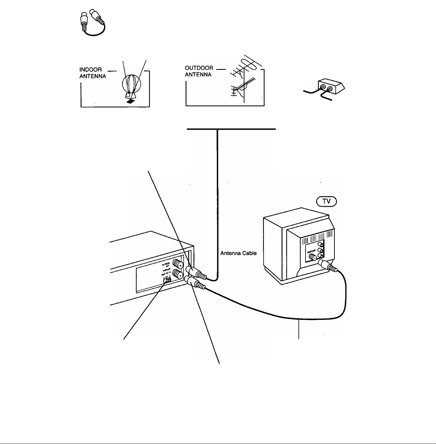
Basic Connection
Cable TV
V
1 Disconnect the antenna or
cable from your TV and connect
it to the VCR (IN FROM ANT.)
( VCR)
or
or
3 Set the Output Channel of your VCR
to Channel 3 or 4 (whichever is not being
transmitted on by a Local TV broadcast).
RF Coaxial Cable
(VCR-TV Connection Cable) (supplied)
2 Connect the VCR to your TV with
the RF Coaxial Cable (OUT TO TV).
r WARNING-----------------------------------------------------------------------------------------------------------------------------
When using “Nut type" RF coaxial cables, tighten with fingers only. Overtightening may damage terminals.
Page 7
Between Antenna and VCR
Between VCR and TV
Case 1; Twin Lead Cable Only
To VCR Terminal
n®
(Flat) Twin Lead
300 Ohm Cable
Case 2: Twin Lead & Coaxial Cables
(Round) 75 Ohm
coaxial Cable
300-75 ohm Transformer
(not supplied)
D
To VCR Terminal
UHFA/HF
Band Mixer
(not supplied)
Case 1: Screw & Plug Type Terminal
UHFA/HF Band
Separator
(not supplied)
RF Coaxial Cable
Case 2: Screw Type Terminal
Case 3: Double Screw Type Terminal
VHF
UHF
TV
VHF
or
UHF
Case 3: Two Twin Lead Cables
(not supplied)
To VCR Terminal
If your TV has both post and plug-type VHF
terminals, the post connection is recommended to
minimize signal loss.
UHFA/HF Band
Separator
(not supplied)
Case 4: Complex TV Terminal
TERMINALS ON BACK OF TV SET
• Connect to one of the ANT terminals and select the
same antenna number on the TV.
TV
VHF
UHF
Page 8
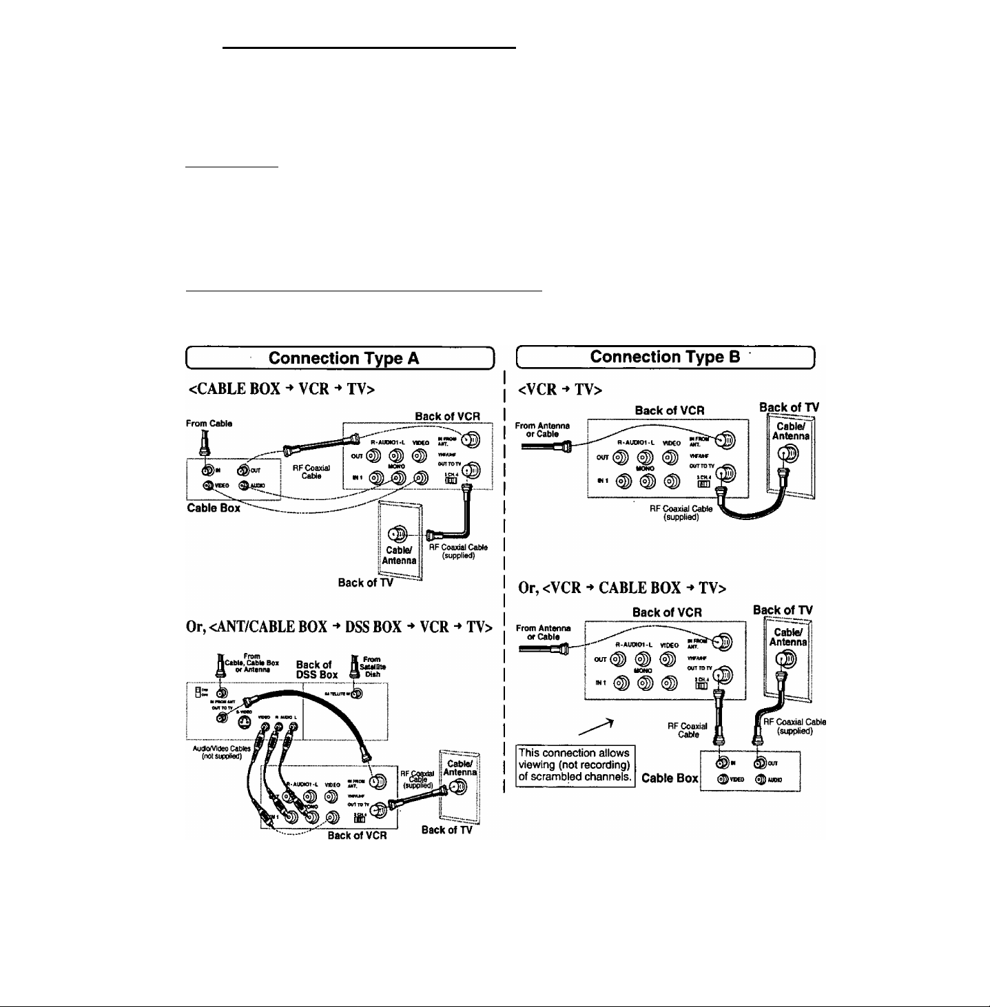
Other Connections
CABLE Connections
All connections on these pages are rhade witti 75 Ohm coaxial cables.
Without a Converter/Descrambler Box
You can:
1) Use your VCR Remote Control to select channels.
2) Program one or more unscrambled channels for
unattended recording.
You cannot:
— record or view scrambled channels with this connection.
IN FROM
CABLE
VCR
With a (CABLE to VCR) Converter/Descrambler Box
You can:
1) Record and view any channel including
scrambled channels; channel selection must
be made at the Cable TV Converter Box.
2) Program one channel for unattended
recording.
You cannot:
— select channels from VCR or TV.
— watch one station while recording another.
— place channels in memory other than the Cable box output channel
IN FROM ANT.
VHF/UHF
OUT TO TV
With a (VCR to TV) Converter/Descrambler Box
You can:
1) Use your VCR Remote Control to select channels.
2) Program unattended recordings of more than
one unscrambled channel.
You cannot:
— record scrambled channels with this connection.
Cable TV
Converter Box
With Two Converter/Descrambler Boxes
If you want to record and
view a combination of
scrambled and
unscrambled channels,
you will need additional
equipment.
This connection requires
two converter boxes, an
A/B switch, and a 2-way
splitter as shown here.
IN FROM
CABLE
IN FROM
CABLE
IN FROM ANT.
OUT
Converter Box 1
VHF/UHF
IN FROM ANT.
V OUT TO TV
8
Page 9
With a DSS Receiver IN FROM
CABLE or Antenna
You can:
1) Record and view any channel including
scrambled channels; channel selection
must be made at the DSS Receiver.
2) Program one channel for unattended
recording.
NOTE: The DSS receiver must be turned off to view
programs from a cable box or antenna. See the
DSS manual for details.
*DSS® is a registered trademark of DIRECTV, INC., a unit of GM Hughed Electronics.
IN FROM
Satellite Dish
OUT TO TV
VHF/UHF
Audio/Video Connections
If your TV has AUDIO IN and VIDEO IN temninals, you can connect your
VCR to them to receive a higher quality picture and sound. If your TV is not
stereo, you can connect a stereo amplifier to the VCR to enjoy stereo sound.
AudioA/ideo Connections
1 Connect the VIDEO OUT terminal on the
VCR to the VIDEO IN terminal of your TV.
2 Connect the “L" and "R" AUDIO OUT terminals on the VCR to the “L” and “R” AUDIO IN terminals of your TV.
3 Set the VIDEO/TV selector of your TV (Monitor/Receiver) to “VIDEO."
NOTE: To use your TV as a VCR monitor, set the VIDEOS selector on the TV (Monitor/Receiver) to “VIDEO."
Use the L Audio In jack for proper sound reproduction when connecting to a monaural TV.
Stereo Amplifier Connections
When you connect your VCR to a Stereo
Component System, you can view the
picture from the VCR while enjoying
stereo from your audio system.
Connect the “L” and “R” AUDIO OUT
terminals on the VCR to the “L" and “R"
AUDIO IN terminals of your stereo.
Note to CABLE system installer:
This reminder is provided to call the CABLE system installer’s attention to Article 820-40 of the NEC in USA (and to the
Canadian Electrical Code in Canada) that provides guidelines for proper grounding and, in particular, specifies that the
cable ground shall be connected to the grounding system of the building, as close to the point of cable entry as practical.
Page 10
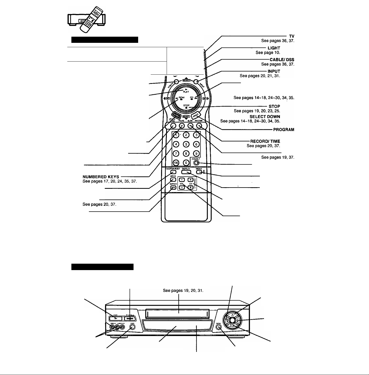
Location of Controls
Remote Control Buttons
EJECT
--------------------------------------------------------
See pages 19,37.
POWER----------------------------------------------See pages 14, 22, 23, 35, 36, 37.
VCR---------------------------------------------------------------------See pages 36, 37.
VCR/ TV
See pages 14, 21,37.
PLAYSee pages 19, 25, 37.
SELECT UP
See pages 14-10, 24-30, 34, 35.
REWIND/ SEARCH
See pages 19, 25, 37.
SET/ BACKSPACE
See pages 16,17, 22, 23, 28, 34, 35.
ACTION
See pages 15-18, 26, 27, 28, 29, 30, 34.
ZERO SEARCH/ 1 MINUTE SKIP
See pages 26, 37.
PAUSE
See pages 19, 20, 31.
COUNTER RESET
See pages 26, 37,
SPEED
SAP/ Hi-Fi
See pages 33, 37.
Light Tower Universal Remote Control
Light button; When the LIGHT button Is pressed, the buttons which can be activated in the selected mode will light and the
selected mode button (TV/VCR or CABLE DSS) will flash for 5 seconds. If no buttons are pressed within 5
seconds, the light wilt turn off in order to converse battery power. Also, while holding down the buttons the
selected mode button will flash so you will be able to see, in the dark, which mode has been selected.
EJECT button: When EJECT is pressed, the tape is ejected from Cassette Compartment.
If EJECT is pressed during recording, the VCR will not respond to the command.
^
r-
eject
FAST FORWARD/SEARCH
See pages 19, 24, 25, 37.
See pages 22, 23, 35.
ADD/ DELETE
See pages 19, 23, 28, 29, 34, 35.
INDEX/ ENTER
See pages 24, 37.
DISPLAY
' See pages 18, 20, 25, 26, 32, 37,
CHANNEL UP/DOWN
(TRACKING UP/DOWN)
See pages 14-17,19-21, 37.
VOLUME UP/DOWN
See page 37.
SET
SLOW
Front View of the VCR
CHANNEL UP/DOWN
TRACKING/V-LOCK
POWER
See pages
14, 22,23, 35,37.
VIDEO Input
Connecter N..
See page
AUDIO Input
Connecter (L/R)
See page 31.
See pages 14-17,19-21,37,
31. \
VCR/TV Selector
See pages 14, 21, 31,37.
10
Cassette Compartment
Multi Function Display
See pages 11,19-23,35.
REMOTE
SENSOR
REWIND/SEARCH
See pages 16, 23, 24, 25.
RECORD/TIME
See pages
20. 23, 27,31.
PLAY
See pages
19, 23, 25,31,37.
FAST FORWARD/
SEARCH
See pages
19,23, 24,25,37.
STOP/EJECT
See pages
19. 20,23,25,31.37.
Page 11
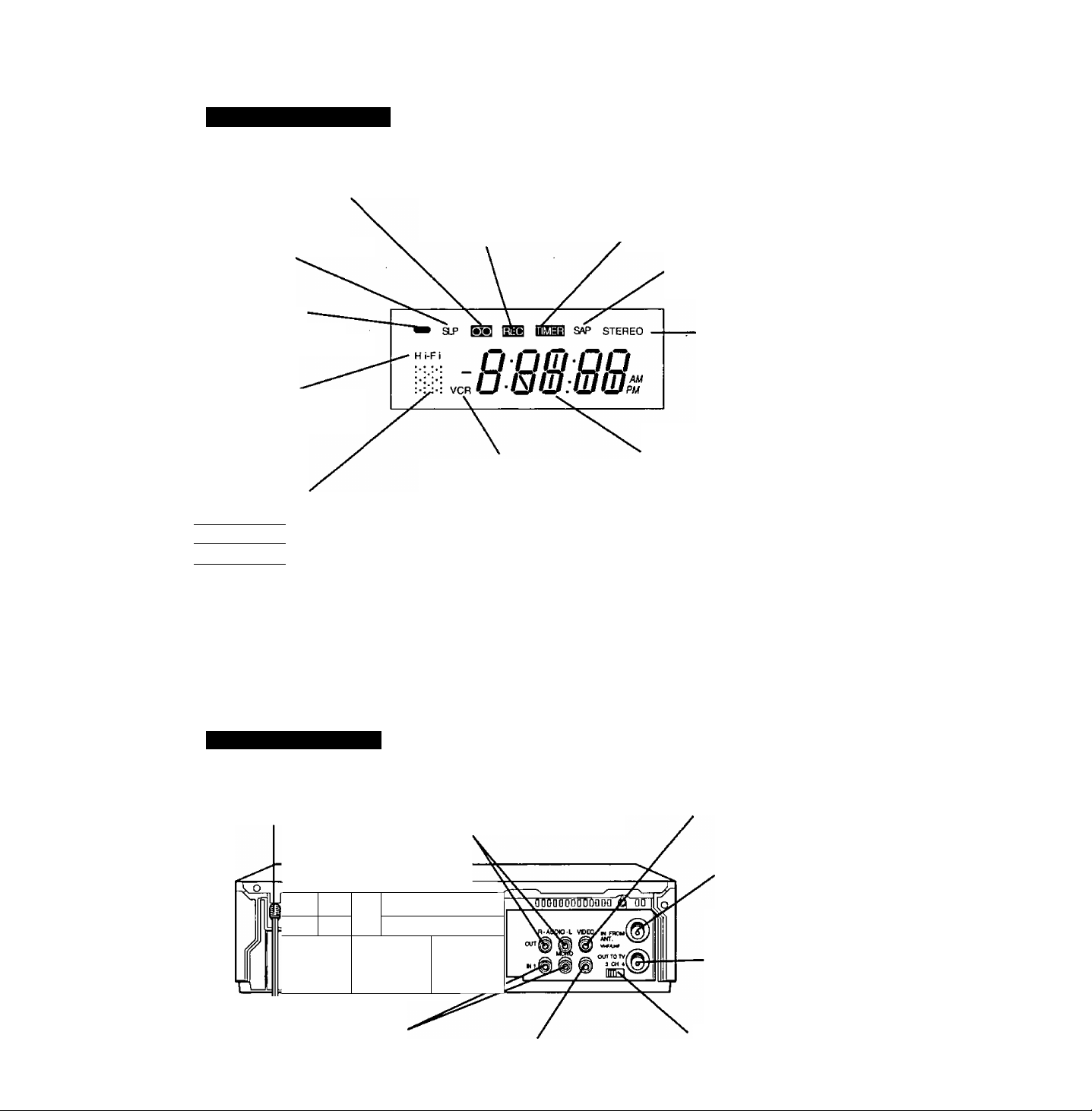
Multi Function Display
Cassette-In Indicator
Lights when a tape is in the VCR.
SPEED Display
Displays the recording speed.
REC(ord) Indicator
Lights during recording.
Timer Indicator
Lights when the VCR is set for a Timer
Recording, or when a length is set for a
normal recording.
The Timer Indicator flashes when a Timer
Recording is set, but a tape has not been
inserted into the VCR.
SAP Indicator
Lights when the station you are
tuned to is broadcasting SAP.
Power Indicator
Lights when power is on.
Hi-Fi Indicator
Lights when Hi-Fi audio is
monitored or played back.
VCR Indicator
Lights when the VCR/TV
Function Indicator
Shows what the VCR is doing.
[Riband ►
iRECland II
►
II
Flashing
► Flashing Fast forward or Forward search
11 Flashing
Record
Record-pause
Playback
Slow motion or Frame advance
Play-pause
Rewind or Rewind search
Cassette ejecting
selector is set to VCR.
Rear View of the VCR
STEREO Indicator
Lights when the station
you are tuned to is
broadcasting stereo.
Clock/Status/Channel Display
Displays the current time.
Briefly displays VCR status when
a function button is pressed.
Briefly displays the channel
number, or “L1” or “L2’’ when a
channel or line input is selected.
Displays the tape counter during
tape operation.
AC Power Plug
While plugged into an AC outlet,
the VCR consumes 3.7 W of
electrical power in OFF condition.
iP if
*
Audio Input Connector (UR)
See pages 12, 31.
rililflfllfionr %n
ft
Audio Output Connector (UR)
See pages 9, 31,32.
-----------
^
Video Input Connector
See pages 12, 31.
Video Output Connector
See pages 9, 31, 32.
VHF/UHF Antenna
Input Terminal
See pages 6-9, 12, 32.
VHF/UHF Antenna
Output Terminal
See pages 6-9,12, 31,32.
Channel 3/4 Switch
See pages 6,14.
11
Page 12
One Time VCR Setup
The setup on pages 14 through 16 is vital for proper VCR operation.
Please read the instructions carefully and in the order presented.
NOTE: These first two pages contain reference material needed for setup on pages 14 -16.
Please look over the information before you begin setup procedure.
Setup Overview
You will be performing the following tasks:
• Setting the language you want on-screen displays to appear in {English, Spanish, French).
• Telling the VCR what kind of equipment you are using to receive channels and how it is connected.
• Entering pertinent cable box or DSS receiver information if used.
• Entering a local PBS channel so that the VCR can receive auto clock set data. (Not available in all areas.)
• Placing channels in memory and setting the clock.
Please Note Which Connection Type You are Using.
Make sure all equipment is hooked up as described on pages 6-9,
The diagrams below illustrate some of the basic connection types.
Confirm which type you used for later reference.
ONE TIME SETUP IMPORTANT NOTES:
• For detailed DSS receiver connection instruction, please see your DSS operating manual.
• The DSS receiver must be turned off to view programs from the cable box or antenna.
• If you use a DSS receiver, it must be turned off for auto clock set.
• If your cable box is not remote controllable, it must be tuned to your PBS channel.
• If you use AudioA/ideo Jack connection between the VCR and cable box or DSS receiver, you must also
connect the RF coaxial cable in order to use the auto clock set and channel auto set features.
12
Page 13
Cable Box/ DSS Receiver Code Number List
If your cable box or DSS receiver is remote controllable, refer to this list during setup on page 14.
Cable Box
Brand
_____
Archer
.....................................
Cabletenna
Cableview
Century........................................... 44,51,59,75
Citizen
Components
Curtis............................................. 08, 09, 53, 61
Diamond
Eagle
Eastern
GC Brand
Gemini
General Electric........................................01, 57
General Instruments
..................
Hamlin
Hitachi...................................................... 31,79
Jdsco • * * ..............*
Jerrold"”””roV, oi 0^^ 68
Macom............................................................31
Magnavox.......................................................26
Matsushita................................................ 16,17
Movietime
NEC...................................................... 32,38,40
Novavision................................... 08,09,53,61
NSC
Oak
..................................................
Oak Sigma
Panasonic.................................................16,17
Philips
Pioneer......................................................05, 06
Pulsar
Quest
Radio SHACK, RECOTON
RCA........................................................... 16, 17
Realistic
........................................
.........................
...............................
..................................
.............................................
...........................
...........................................................
..........................
............................................................
01, 02, 03, 04, 34, 55, 83, 65, 67, 68
...................
.....................................
.....................................................
........................................
...............................
................................
........................................................
.....................................
14, 15. 28, 41, 102, 103, 104
04, 30, 42,44, 52, 63
04. 30, 42, 44, 52, 63
13, 20, 22, 26, 40, 58, 62
04, 30, 42, 44, 52, 63
07,13, 20, 23, 24, 50
04, 30, 42, 44. 52, 63
Code Numbers
01,05, 06, 44, 63
01,44, 63
32,39,42,44
01,44, 63
32, 39, 42,44
32, 38, 40
11. 46, 101
11,46,101
..........
44, 51, 59, 75
.. 44, 51,59, 75
28
04
....
04
05,06
Brand
______________________
Regal
.....................
Regency
Rembrandt
Samsung
Scientific Atlantic
Sheritech.........................................................27
Signal............................................................. 26
SL Marx
Spucer
Standard......................................... 32, 39, 42, 44
Stargate
Sylvania.......................................................... 19
Telecaption
Teknika............................................................74
Teleview
Texscan
Tocom
Toshiba
Unika
Universal
Viewstar
Vid Tech
Vidtek.........................................................36, 64
Videoway............................................. 07, 23, 50
Zenith................................................... 07, 23, 50
..........................................................
..................
.................................
.................
.......................................................
...........
.....................................................
.........................................
.....................................................
.......................................
...........................................................
...................................................
.................................
......................
..........................................................
14, 15, 28, 41, 102, 103, 104
01,29, 32, 39, 42, 44, 63
........................
06, 32, 40, 42, 43, 44. 52, 63
04, 06, 30, 32, 40. 42, 44, 52, 63
13, 20, 22. 26. 40, 58, 62
Code Numbers
28
05, 06, 32, 40, 42
08, 09, 61, 53
16,17
77
06, 32, 40, 42
18, 19
01.33, 34, 42, 66
36
01,44, 63
42, 43, 44, 52, 63
64
DSS (Digital Satellite System Receiver)
Hitachi............................................................ 93
Hughes........................................................... 93
Magnavox 1/ Uniden 1
Magnavox 2/ Uniden 2
Panasonic.......................................................96
RCA.................................................................97
Sony.........................................................98, 105
Toshiba
..........................................................
..................................
..................................
94
95
92
Note: During setup you wilt be instructed to enter your brand code number. As some brands have multiple
codes, it may be necessary to try different codes to attain the proper results.
These codes are for Cable box or DSS Box setup for Auto Clock and VCR Plus+ recording only.
For TV/Cable Box Multi-Brand Control operation, please see page 36.
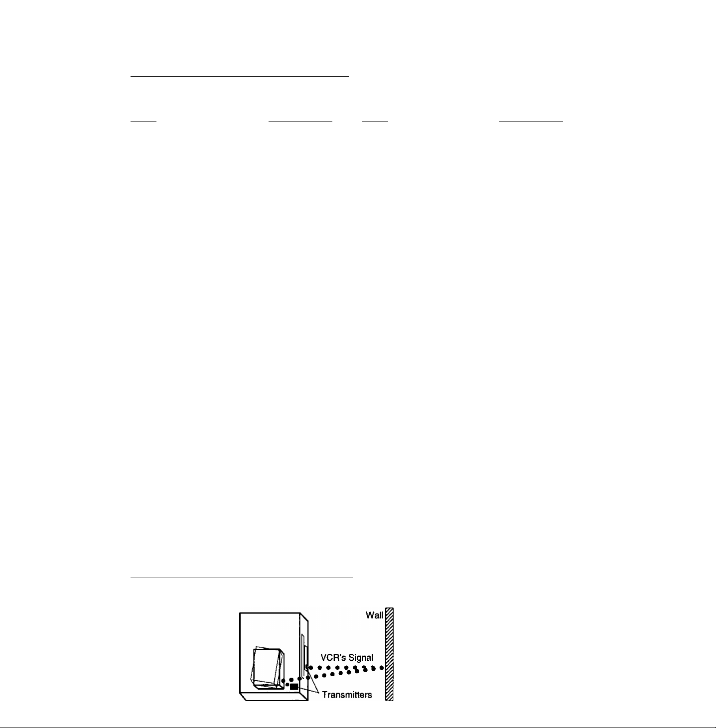
Positioning Your Cable Box or DSS Receiver
If your cable box or DSS receiver is remote controllable, place it on or near the VCR as shown in the example
below. The VCR transmits an Infrared signal from two locations. Be sure not to cover the transmitter windows.
13
Page 14

One Time VCR Setup
^Important: If the remote control POWER, ACTION, PROG, CHA/T, INDEX or ADD/DLT button does
not work when pressed, press the VCR button on the remote and try the button again,
When the VCR is turned on for the first time,
it automatically enters the setup mode.
Setup includes the following:
• Choose the language for on-screen menus
and messages.
• Tell the VCR how your equipment is hooked up
(pages 6-9) so the VCR can correctly place
channels into memory.
• Get the VCR ready for clock set.
To Set the Language, Cable/DSS
Receiver, Channels and Auto Clock
1
Turn the TV and VCR on/
2 Tune your TV to the VCR output channel (the same
one you set on the back of the VCR: CH3 or CH4).
• if you used audio/video jack connection, tune the TV to its video input.
Press CH A for English
on-screen displays.
Or, press CH T for Spanish
on-screen displays.
Or, press VCR/TV for French
on-screen displays.
• You can also set the language using the buttons on the VCR.
• If the wrong language is set, see the “Reset all VCR Memory
Functions” section on page 5.
• The VCR should be connected to an antenna or cable box
(page 6-9).
SELECT U\NGUAGE
PUSH VCR CH A: ENGLISH
OPRIMIR VCR CH T:ESPANOL
APP. VCR/TV : FRANÇAIS
as ATM ► only. Use the buttons on the VCR for
play, stop, rewind, and fast forward functions.
When a program screen is displayed, the REC, FF,
REW, and PLAY buttons on the remote control and
the VCR function as ATM ► only. (See Timer
Recording Using VCR Buttons on page 23.)
Press AT to select your hookup,
and then press ► to set.
• If you selected “CABLE/DSS BOX ►VCR
►TV,” continue with step 5. If not, go to
“Alternate Instructions on page 16.
• If you are using the CABLE/DSS BOX^
VCR/TV connection method, only the
cable box output channel will be placed in memory.
Press AT to select your cable
box or DSS receiver output
channel number, and then
press ► to enter.
• If necessary, refer to your cable
box manual.
• If both a cable box and DSS receiver are used,
set the output channel of the OSS receiver,'
• If you are using Audio/Video jack
connections to your cable box, select and
set “VIDEO OUT as the output channel.
Press AT to select your cable
box or DSS receiver code number,
and then press ► to enter.
(Refer to the list on page 13.)
• If your cable box or DSS receiver
doesn't have a remote control,
select “NO REMOTE.” Then, go to
Alternate Instructions on page 16.
• This determines whether the VCR will
control your cable box or DSS receiver.
SELECT HOOKUP
CABLE/DSS BOX^VCR^TV
VCR^CABLE/DSS B0XA7V
VCRUV
SELECT;* ▼ KEY
SET :► KEY
END lACTION KEY
SELECT HOOKUP
CABLE/DSS BOXPVCRPTV
CABLE/DSS BOX OUTPUT CH
SELECT:* ▼ KEY
SET :4 ► KEY
END ;ACTION KEY
ENTER CODE NUMBER
REFERRING TO MANUAL
SELECT
* » KEY
SET
► KEY
END
ACTION KEr
14
Page 15

tf you use a cable box,
tune it to channel 02.
If you use a DSS receiver,
tune it to channel 270.
7 Press ► to continue.
• “NOW TRANSMITTING" appears.
If Cable Box
PLEASe TUNE YOUR CABLE
BOX TO CH02.
If DSS Receiver
PLEASE TUNE YOUR DSS
RECEIVER TO CH 270,
PROCEED ;► KEY
END :ACTION KEY
if the Auto Clock Set
displayed time is incorrect...
If you use a cable box and receive
more than one PBS station, try auto
clock set again.
Follow the “To Set or Reset the Clock"
section on page 17 and when the
instructions call for you to enter a PBS
station, enter the one you have not
tried yet.
8 Press AT to select
“YES” or “NO," and then
If Cable Box
tS YOUR CABLE BOX
RECEIVING CH 09 T
press ► to enter.
If you use a cable box and
selected "YES," go to step 9.
If you use a DSS receiver
and selected "YES," go to
“Alternate Instructions”
on page 16.
If you selected “NO," the screen
in step 6 on page. 14 will reappear.
Try entering a different code
assigned to your brand and/ or
repositioning the equipment (see page 13).
If the answer is stiil “NO," cable box or DSS receiver
controi is not available.
For channel and clock auto set, press ACTION to display
the “SET UP CHANNEL” screen. Then, press AT to select
“AUTO SET." Now, press ► and CH A to start the auto set.
SELEC
SET
El
If DSS Receiver
(S YOUR DSS RECEIVER
RECEIVING CH 200?
YES
BE
SELECT ;A^ KEY
SET ;► KEY
END :ACT I ON KEY
_______________
Confirm that your cable box is on
and that your DSS receiver is off.
PLEASE ENTER YOUR LOCAL
9 Press AT to select your
PBS CHANNEL ON CABLE BOX
local PBS channel number
you receive on your cable
box, and then press ^ to
display the “CLOCK AUTO
SELECT;A ▼ KEY
SET ;► KEY
END : ACT I ON KEY
SET screen.
10 Press CH A to start Auto
Clock Set.
• If you iive near a different time
zone, be sure to enter the PBS
channel in your time zone.
• “AUTO CLOCK SET
PROCEEDING" appears.
CLXK AUTO SET
CONNECT ANTENNA CABLE
AND IF YOU USE A CABLE
BOX, TUNE IT TO YOUR
LOCAL PBS CH THEN, . .
PLEASE PUSH CH UP KEY
If “AUTO CLOCK SET IS
INCOMPLETE” appears...
The screen below will appear on
screen if auto clock set data is not
available in your area.
AUTO CLOCK SET
IS INCOMPLETE
PUSH ACTION TO SET CLOCK
Press ACTION to display the “SET
CLOCK" (manual) screen, and
then do steps B and C on page 16.
Note:
If you use a cable box and receive
more than one PBS station, you may
exit the manual clock set screen and
try auto clock set again.
Follow the “To Set or Reset the Clock”
section on page 17 and when the
instructions call for you to enter a PBS
station, enter the one you have not
tried yet.
11
This display appears when
auto clock set is completed.
Confirm that the time is
correct and press CH A
to exit.
Auto clock set will be performed when the VCR is turned off the first time each day. If you use a cable box
and you want auto clock set to be performed, the cable box must be left on and tuned to the PBS channel
before the VCR power is turned off.
1/ 4/2000 TUE 12:OOPIi
SETTING : CH 02
AUTO CLOCK SET
VD : PUSH CH UP KEY
OST:ON
COMPLETED
15
Page 16

One Time VCR Setup
‘Important: U the remote control POWER, ACTION, PROG, CHA/T, INDEX or ADD/DLT button does
not work when pressed, press the VCR button on the remote and try the button again.
Alternate Instructions
Complete the following steps if, any of the following applies:
• You selected connection type 2 (VCR^CABLE/ DSS
BOX^TV or VCR^tV) in step 4 on page 14.
• You selected “NO REMOTE" in step 6 on page 14
(your cable box or DSS receiver is not remote
controllable).
• You use a DSS receiver and selected “YES” in step
8 on page 15.
1 Turn on the cable box and
set it to the local PBS channel.
• If you live near a different time
zone, make sure to set the
channel in your time zone.
• If you use a DSS receiver,
it must be turned off.
Press CH A* to start Channel Auto Set and
Auto Clock Set.
• The following messages appear.
“CH AUTO SET PROCEEDING"
“AUTO CLOCK SET PROCEEDING"
OWJNEL/CLOCK AUTO SET
CONNECT ANTENNA CABLE
ANO IF YOU USE A CABLE
BOX. TUNE IT TO YOUH
LOCAL PBS CH THEN, , .
PLEASE PUSH CH UP KEY
This screen appears to confirm that
auto clock set is completed.
1/ 4/2000 TUE 12:OOPH
3 Confirm that the time is
correct and press CH A
to exit.
If this screen appears, auto
clock set is not available in
your area. Please set the clock
manually as described below.
SET CLOCK screen.
B Press AT and ► to
select and set the month,
date, year, time, and
DST. (Daylight Saving Time).
To Make Corrections,
repeatedly press ► to move the cursor
to the incorrect entry and make the correction.
C Press ACTION twice to start
the clock and exit this mode.
END : PUSH CH UP KEY
AUTO aOCK SET
PUSH ACTION TO SET CLOCK
-\4/—A Press ACTION to display the
SB.ECT:A ▼ KEY
SET :► KEY
END lACTION KEY
uae^ian.1
SET :-« ► KEY
START ¡ACTION KEY
SETTtNG : CH 02
AUTO aOCK SET
IS INCOMPLETE
DSTiON
COMPLETED
OST:ON
If the displayed time and DST.
are not correct...
If you happen to live close to two time zones,
the VCR may have recognized the PBS
channel (setting channel) in the wrong time
zone. Please do the following to correct the
situation.
a Make a note of the SETTINGiCH number
shown on screen and press CH A to exit.
b Delete the setting channel from the VCR
channel memory. (See the “To Add or
Delete a Channel" section on page 17.)
c Press ACTION to display the menu.
d Press AT to select “SET CLOCK," and then
press ► to display the “SET CLOCK” screen.
e Press AT and ► to select and set “AUTO
CLOCK SET."
f Follow the One Time VCR Setup
instructions on pages 14-16.
• If you use a cable box and have multiple PBS
stations, tune the cable box to a different PBS
station and try auto clock set using the menu.
16
Page 17

To Change On-Screen Display Language
1 Press ACTION to
display the menu,
2 Press AT to select
the language.
English: LANGUAGE
Spanish: IDIOMA
French: LANGUE
3 Press ► repeatedly to change the language.
MENU
------
--------------
MENU
SET UP VCR
SET UP FEATURE
SET CLOCK
SET UP CHANN
SELECT:A v
► KEY
SET
ACTION KEY
END
PREPARAR VCR
FIJACION DE FUNCIOI
FIJAR RELOJ
FIJAR CANAL
iwiMiiiamtuREsi
ELEGIRIA ▼
FIJAR
TERMINARiACTION
4 Press ACTION to exit this mode.
------
REGLASE MAGNETOSCOPE
REGLAGE MAGNETO SUPPLEM
REGLAGE HORLOGE
REGLAGE CAN^
MENU
SET UP VCn
SET UP FEATURE
SET CLOCK
SET UP CHANNEL
SET ;► KEY
END :ACTI ON KEY
MENU
lAL
__
ílBgn FRANÇA IS
;sD£
SEL. :A T
REGLER: A
FIN lACTtON
ENGLISH
To Add or Delete a Channel
1 Select a channel using the
NUMBERED keys to add
or CH A/T to delete.
2 Press ADD/DLT to add
or delete the channel.
• To select a channel
once it's deleted,
use the NUMBERED keys
on the remote control.
To Set or Reset the Clock
In case the clock is wrong, or a power failure occurred.
1 Press ACTION to display
the menu.
2 Press AT to select “SET
CLOCK," and then press
► to display the “SET
CLOCK" screen.
3 Press AT to select
“MANUAL." and then
press ► to display the
SET CLOCK screen.
4 Press AT and ◄ ►to
select and set the date,
time and DST.
(Daylight Saving Time).
5 Press ACTION twice to
start the clock and exit
this mode.
• For Auto Clock Set, select “AUTO CLOCK SET,"
and then follow the One Time VCR Setup instructions
on pages 14-16.
--------------
MENU
---------------
SET UP VCR
SET UP CHANNEL
iniftUAMAMfiiiP-FMr:i
---------
SET CLOCK
AUTO CLOCK SET
SELECT:A » KEY
SET :AKEY
END :ACTION KEY
SET CLOClM¿-jj¿
------------
1/ 4/2000 TUE 12:(
SELECT;A ▼ KEY
SET ► KEY
END :ACTION KEY
______________________
To Replace Channels in Memory
In case you have cable installed, etc..
--------------
MENU
1 Press ACTION to display
the menu.
2 Press AT to select “SET
UP CHANNEL,” and then
press ► to display the
“SET UP CHANNEL” screen.
3 Press AT to select
“ANTENNA.” and then
press ► to set your antenna
system (TV or CABLE).
4 Press AT to select “AUTO
SET," and then press ►
to display the “CHANNELy
SET UP VCR
SET UP FEATURE
IDIOMA/LANGUE:ENGL ISH
SELECT:A ¥ KEY
SET :► KEY
END : ACT I ON KEY
------
SET UP CHANNEL
AUTO SET
CHANNEL CAPTION
CABLE/DSS BOX SET UP
VCR P1u*+ CH SET UP
SELECT
SET
END
----------------
CABLE
A ¥ KEY
► KEY
ACTION KEY
-----------
CLOCK AUTO SET screen.
Follow the One Time
VCR Setup instructions on
page 14-16.
• Clock Auto Set will be
performed when channels
Oi/WNa/CLOCK ADTO SET
CONNECT ANTENNA CABLE
AND IF YOU USE A C/^E
BOX, TUNE IT TO YOUR
LOCAL PBS CH THEN. . .
PLEASE PUSH CH UP KEY
are replaced in memory.
To cancel, press STOP when “AUTO CLOCK
SET PROCEEDING" appears on-screen.
To Setup the VCR in Case a Cable Box or
DSS Receiver was Installed or Replaced
--------------
1 Press ACTION to display
the menu.
2 Press AT to select “SET
UP CHANNEL,” and then
press ► to display the “SET
MENU ----------------
SET UP VCR
SET UP FEATURE
SELECT
A ¥ KEY
SET
► KEY
ACTION KEY
END
SuTenglish
UP CHANNEL" screen.
------
3 Press AT to select “CABLE/
DSS BOX SET UP,” and
then press ► to display the
“SELECT HOOKUP" screen.
• To exit this mode, press
ACTION three times.
SET UP CHANNEL ----------
ANTENNA : CABLE
AUTO SET
CHANNEL CAPTION
VCR Pk»»+ CH SET UP
SELECT;A ¥ KEY
SET ;► KEY
END : ACT I ON KEY
4 Press AT and ► to select
and set “CABLE/DSS BOX
► VCR ► TV,” and then
VCRaCABLE/DSS box^tv
vcratv
continue with steps 5-8 on
pages 14, 15.
If these steps are completed,
SELECT:A ¥ KEY
SET :► KEY
END lACTION KEY
the “SET UP CHANNEL" screen will appear.
When Using the 100 key
When selecting CABLE channels 100 to 125 with the
NUMBERED keys, first press the 100 key and then
enter the remaining two digits.
For example, to select channel 125:
Press NUMBERED keys 100, then 2, then 5.
This VCR will accurately maintan its calendar up to Dec. 31,2096,11:59PM.
Normal TV or Cable channels are automatically selected and placed in memory depending on how your VCR
is hooked up.
If you change your Cable Box or DSS Receiver, please perform the “To Set or Auto Clock SeT section above.
17
Page 18

On-SCTeei^isplay^OSD)
*lmportant: tf the remote control POWER, ACTION, PROG, CHA/T, INDEX or ADD/DLT button does
not work when pressed, press the VCR button on the remote and try the button again.
Function & Channel Display
When a function button is
pressed, e.g. PLAY, or
you change channels,
a 4 second display
appears first in large
and then small characters.
Warning and Instruction Displays
These displays will alert you of a missed operation or
provide further instructions.
If no active channels are found
for CHANNEL MEMORY...
(See page 16.)
NO CH FOUND
PLEASE CHECK ANTENNA
CABLE CONNECTION THEN
PUSH VCR CH UP KEY AGAIN
(Some Station names may
also appear if Channel
Caption is set. See pages 28, 29.)
Menu Screen
1 Press ACTION* to
display the menu.
2 Press AT and ^ to
make your selection.
SET UP VCR
SET UP FEATURE
imigga
SET UP CHANNEL
IDIOMA/LANGUE: ENGLI SH
SELECTiA T KEY
SET :► KEY
END :ACT I ON KEY
If you attempt to set or review
a Timer Recording and the
Clock is not set...
(See page 22.)
After a Timer Program has
been set...
(See page 22.)
PLEASE SET CLOCK
BEFORE PROGRAMMING
TURN VCR OFF
FOR TIMER RECORDING
LEAVE CABLE BOX POWER ON
AND
To get the most from each feature,
please read the Operating Manual
before attempting any operation.
If you press REC on the
remote control or VCR,
and a cassette is inserted
CHECK CASSETTE
RECORD TAB
with no record tab...
VCR Status & Clock Display
(See page 20.) '
Press DISPLAY to dispiay or remove the
overlay shown below.
Function
Status
Rec Time
Remaining
(OTR mode only
see page 20.)
Broadcast Audio
Being Received
(See page 32.)
• This display will
disappear in 5 seconds.
Current Time
REC 12:00AM ABC
0:25 -0:12:34
► STEREO SP
► SAP
MONO
Channel Caption
(See pages 28, 29.)
Counter
Tape Speed
(See page 5.)
Blank Tape/ No Video Signal Indication
Whenever a blank section of a tape comes up in Play
mode, or when the selected channel has no broadcast
signal with the Blue Back ON/OFF Feature (page 30)
set to ON, the TV screen will turn solid blue.
If you press PLAY, FF, REW,
or REC on the remote
control or VCR without
a cassette inserted...
(See pages 19, 20.)
If you press POWER or STOP
during a Timer Recording...
(visible in VCR mode only)
(See page 23.)
If head cleaning becomes
necessary while playing
back a tape...
(See page 5.)
If you press a function button
other than STOP/EJECT or
POWER on the VCR, or STOP
or EJECT or POWER on the
remote control while the VCR is
in VCR Lock mode...
(See page 27.)
If you press POWER, ACTION
or PROG on the remote white
in TV or CABLE/DSS mode...
(See pages 36, 37.)
NO CASSETTE
PLEASE INSERT A CASSETTE
TO CANCEL TIMER REC
PUSH POWER THEN STOP KEY
VIDEO HEADS MAY
NEED CLEANING
PLEASE INSERT HEAD
CLEANING CASSETTE
OR REFER TO MANUAL
END:PLAY KEY
VCR LOCK ACTIVATED
NOW TV/CA8LE/DSS MODE
PLEASE PUSH VCR KEY
ON REMOTE
18
Page 19

Haybacj^^kpe
Check list before you begin.
d All connections are made.
(See pages 6-9.)
□ TV and VCR are plugged in.
□ TV is turned on and set to the VCR
channel (CH3or4).
1 Insert a cassette.
• VCR power comes on automatically.
• “VCR" lights in the Multi Function Display.
2 Press PLAY on the remote or VCR to start playback.
• Playback begins automatically if cassette has no record tab.
3 Press STOP on the remote or VCR to stop playback.
• To rewind the tape, press REW.
4 Press EJECT on the remote or VCR to eject the
cassette.
• You may eject a cassette with power on or off.
To Find a Particular Scene During Playback
Press REW or FF during playback to search for a scene.
• Search speed for SP mode tapes is 7 times and SLP mode tapes is
21 times the normal speed.
• Some noise bars will appear during search.
Caution:
Please inspect your cassette tapes
and remove any loose or peeling
labels to prevent them from
becoming jammed in your unit.
Special Effects During Playback
These features work best in SP or SLP mode. The sound will be muted.
Slow Motion Playback
Press SLOW to start slow motion playback during playback.
Press PLAY or SLOW to release.
Still (Freeze^ Frame Picture
Press PAUSE to freeze and release the picture.
• To reduce picture noise, first press SLOW. Then, use CH
(TRACKING) A/T to clear up the picture. Now, press PAUSE.
Frame bv Frame Advance
In Still mode, hold down SLOW to advance the still picture one
frame at a time. Press PAUSE to release.
Features for a Quality Picture
Digital Auto Picture
This feature automatically controls the video output signal for
less noise depending on the tape condition.
Digital Auto Tracking
This feature continuously analyzes the signal and adjusts for
optimum picture quality.
Manual Tracking Control fto reduce picture noise)
Use during Playback and Slow Motion mode to reduce picture
noise. Press CH (TRACKING) A/T during playback until the
picture clears up. To return to Auto Tracking mode, press
POWER off and then on again.
V-Lock Control (to reduce picture jitter^
In Still mode, CH (TRACKING) A/T operate as a
V-Lock control. Press A/T until the picture is stabilized.
After the VCR is in Still or Slow mode for 3 rrtinutes, it
vrill switch to the Stop mode automatically to protect the
tape and the video head.
19
Page 20

Record On a Tape
*lmportant: If the remote control POWER, ACTION, PROG, CHA/T, INDEX or ADD/DLT button does
I^c
Q All connections are made.
{See pages 6-9.)
Q VCR is plugged in.
Q TV is turned on and set to the VCR
channel (CH 3 or 4).
^CHANNEL j
£ Up/Down
\ ..
m o \\—
not work when pressed, press the VCR button on the remote and try the button again.
1
Check list before you begin.
4
li
_______
—
—Dm
Multi Function Display ^
Insert a cassette with record tab
• VCR power comes on automatically.
Press CH A/W* * or NUMBERED
keys to select a channel.
• Or, press CHANNEL A/V on the VCR.
• Holding down CH A/V will increase
the channel search speed.
• To record from an outside source,
press CH A/T or INPUT to select
“LINE1" or “LINE2" (see page 21).
Press SPEED to change the
recording speed.
• SP = Standard Play ,
LP = Long Play
SLP = Super Long Play
(See page 5.)
Press REC/TIME on the remote control or VCR to
start recording.
• To edit out unwanted portions, press PAUSE to pause the
recording in progress.
To release, press PAUSE again.
(After tile VCR has been in Pause mode for 5 minutes, it will
stop automatically to protect the tape and video head.)
One Touch Timer Recording (OTR)
The VCR starts recording and turns itself off at a preset time.
In step 4, press REC/TIME repeatedly to set the length of the
recording. Each press will change the stop time as shown.
Normal Ree—►0:30—*-1:00
L
4:00-*—3:00*4—2:00*4-1:3Q
“TIMER” lights in the Multi Function Display.
The remaining recording time can be displayed by pressing
DISPLAY in OTR mode.
J
5 Press STOP to Stop recording.
• Or, press STOP/EJECT on the VCR.
20
Page 21

CHANNEL Up/Down
Selecting the Input Mode
Press INPUT.
The display will change in the order below.
Channel
Number
r
Press CH A/T.
The display will change in the order below.
1—2—3
c
IMPO.
'LINE2-«-LiNE1-*- 125 or 69
• LINE1: For rear audio/video connection.
• LINE2: For front audlo/video connection.
• When LINE is selected, “LI" or “L2" is displayed in the
Multi Function Display for about 4 seconds.
-►LINEV
■LINE2
or
---------
(CABLE) (TV)
D
D
VCR/TV
O © ©
© © ©
© © ©
0 ©
INPUT
CHANNEL
Up/Down
Record One Program While Watching Another
1 Press VCR/TV while recording is in progress to turn off
the VCR indicator in the Multi Function Display.
2 Use the TV channel controls to select a program. The
VCR will continue to record your program while you
watch any channel you choose.
• To switch back and forth between the recording and viewing
channel, press VCR/TV.
Selecting Channels at the VCR
1 Turn your TV and VCR on.
• VCR Indicator lights on the Multi Function Display.
If indicator doesn’t light, press VCR/TV to turn it on.
2 Use CH A/T on the remote control or VCR to select
channels.
• To switch back to TV channel selection, press VCR/TV to
turn VCR indicator off, or simply turn the VCR power off.
21
Page 22

Timer Recording
*lmportant: If the remote control POWER, ACTION, PROG, CHA/T, INDEX or ADD/DLT button does
not work when pressed, press the VCR button on the remote and try the button again.
You can set up the VCR to record a one
time, daily, or weekly program while you are
away or otherwise occupied. Up to 8
programs can be stored in memory.
[^^Check list before you begin.
Q All connections are made.
(See pages 6~9.)
n TV and VCR are plugged in and turned on.
tU VCR/rv selector is set to “VCR."
□ Clock is set to correct time.
Q Record tab in place. (See page 5.)
1 Press PROG* to display the
“SET PROGRAM” screen.
--------
SET PRCCRAM
VCR Pit«* PROGRAM
TIWEfi PROGRAM
................
2 Press AW to select “TIMER
PROGRAM,” and then press ►
to display the program screen.
• If a program is already in memory, press AW
and ^ to select an unused program number.
3 Press AW and ► to select and
set one of the following:
• 1-31 =Onetime recording
• DAILY =Same time MON-FRI
• WEEKLY (SUN-SAT) =Same time once a week
Example ^8—9
Today’s Date — 7 SELECT A / ▼ Selection Order DAILY
(^WEEKLY...........WEEKLY
4 P№ee A^ and ^ ^ Remaining Items to be set:
Press AT and
“T Kress AT ana , start time -stop time
to select and set each
of the remaining
items at right.
To Make Corrections
Repeatedly press ► to move the cursor to the right, or to
move to the left to the incorrect entry and make the correction.
(SAT)
.....
'31 1—2'
• CH(annel) number, or LINE
• Category (N/A [not applicable],
• Speed (SP. LP. SLP)
SELECT:* ▼ KEY
SET :► KEY
END :PROG KEY
START STOP CH
Wf\
CATEGORY :N/A
BiiBBHaKQB
SELECT
* ▼ KEY
SET
► KEY
END
PROG KEY
.....
6
___
(MON) (SUN)
for outside source recording
SPORTS, MOVIE, COMEDY,
MUSIC, DRAMA)
WEEKLY_J
( O00O )
O © ©
© © ©
© 0 ©
_ _ WDCXT
cxxMTtM kiifT D«puty
© © ©
O CD
O
0 Qj
HfXt
□ I
Q 0 0-
Important notes when using a DSS receiver
• When recording programs via a DSS
receiver, the DSS receiver must be left on.
• When recording programs via an antenna or
cable, the DSS receiver must be turned off.
A cassette with no record tab is ejected and “TIMER” flashes when the power is turned off to set the timer.
If the start times of two programs oveilap, ttie lower numbered program will have priority.
If the start time for a timer recording comes up during a normal recording or One Touch Recording (page 20),
the timer recording will not be performed.
If there is a power interruption of more than one minute, the recording will not be performed or continue.
5 Press PROG to end the program.
• This screen appears for confirmation.
If you use a DSS receiver and enter a
channel number of 100-125, the screen
at right appears.
P DT START STOP CH SPD
2
----------
3
--------
4
--------
CANCEL
SELECT
ENTER
END
IS IT CABLE OR OSS
RECEIVER?
Press AT to select “DSS" or
“CABLE,”and then press ► to enter.
• The confirmation screen appears
SELECT:* ▼ KEY
SET :► KEY
above right after this selection.
To Enter More Programs
Press AT and ► to select and set a blank
program number, and then repeat steps 3 and 4.
Press PROG to exit this mode.
Press POWER off to set the timer.
• When recording programs via a cable
box, make sure the cable box Is left
ON and tuned to the desired channel.
Multi Function Display
ADO/D
1 -8:*
► KEY
PROG
-¡¡13113-
-T KEY
▼ KEY
CEY
22
Page 23

POWER
Cancel a Timer Recording:
(Recording is in progress)
Press POWER and then STOP within 10 seconds to
cancel the timer recording.
• The TIMER indicator goes out in the Multi Function Display.
Replace Program Contents:
(Recording is not in progress)
1 Press PROG to display the “SET
PROGRAM” screen.
2 Press AT to select “TIMER
PROGRAM," and then press ► to
display all currently set programs.
3 Press AT and ► to select and
set a program number.
(See page 22.)
4 Press AT and to select
and set replacement timer
information.
5 Press PROG twice to exit this mode.
---------
SET PHOGHAM
VCR Pha4 PBQGBAM
P DT START STOP CH SPO
Q------;
------------
2 8 10:OOP12:OOP125 SP
3 10 8:00P 9:OOP 10 SP
4 SU 9;OOP10:OOP L LP
SELECT 1-8:a ▼ KEY
ENTER :► KEY
END :PRCX3 KEY
Bfcrel/ START STOP CR
CATEGORY:SPORTS
SELECT:A Y KEY
SET :4 ► KEY
END : PROG KEY
Review or Clear Program Contents:
(Recording is not in progress)
1 Press PROG to display the “SET
PROGRAM" screen.
2 Press AT to select “TIMER
PROGRAM,” and then press ► to
display all currently set programs.
3 Press AT to select a program
number.,
4 Press ADD/DLT if you want
to clear the program.
5 Press PROG to exit this mode.
SET PROGRAM
P DT START STOP CH SPO
2 8 1O;OOP12:O0P125 SP
3 10 8;00P 9:00P 10 SP
4 SU 9;00P10:00P L LP
CANCEL:ADD/DLT KEY
SELECT 1-8:A ▼ KEY
ENTER KEY
END :PR0Q KEY
P DT START STOP
a
----------:--------
2 B 10:00P12:0OP125 SP
3 10 8:00P 9:00P 10 SP
4 SU 9:00P10:00P
SELECT 1-B:a y KEY
ENTER :► KEY
END :PR0Q KEY
----------
„ __
CH SPO
L LP
À SELECT V
Timer Recording Using VCR Buttons
(Make sure a cassette tape is not inserted in the VCR.)
1 Hold down STOP/EJECT and press REW to enter the Program mode.
2 Press FF or REC/TIME repeatedly or hold down to make selections.
3 Press PLAY to set the item and move on.
• To make corrections, repeatedly press PLAY to move the cursor to the right,
or REW to move to the left to the incorrect entry and make the correction,
4 Press STOP/EJECT and REW together to display program contents
after all items have been entered.
• You cannot clear programs with the VCR buttons.
5 Hold down STOP/EJECT arid press REW, (release REW first, and
then release STOP/EJECT) to exit this mode.
6 Insert a cassette with record tab and press POWER off to set the timer.
23
Page 24

/M ^ Tape Operation
•Important: If the remote control POWER, ACTION, PROG. CHA/T, INDEX/ M/A SKIP or ADD/DLT button
does not work when pressed, press the VCR button on the remote and try the button again.
VMS Index Search System
Each time you start a recording, an invisible index mark is placed on the tape. When timer recordings are
made, program index and program information (see “Time Stamp Feature" on page 30) are also included.
You can then use these index marks to access or scan your recordings.
Direct Access
(For normal and/or timer recordings)
This feature allows you to go directly to the recording you want from
anywhere on the tape by entering the appropriate index number.
1
Press INDEX* to display the
“SELECT SEARCH MODE” screen.
• This screen appears only if there are timer
recordings on the Program Index list If this
screen does not appear, go to step 3.
2 Press AT to select “INDEX
SEARCH,” and then press ► to display the “INDEX” screen.
3 Press a NUMBERED key to
select the desired recording.
• To calculate the number, see below.
SELECT SEARCH MODE
PROGRAM INDEX SEARCH
Press REW or FF to start a reverse
or fonvard search.
• When the designated location is reached,
the VCR goes into Playback mode.
To calculate the Index Number
Count forward or backward each recording starting point, including
the recording you want to see, from wherever you are on the tape.
Example 1:
If you are watching recording 4 and you want to watch recording 2, count the
start points to number 2. The total is 3. Enter 3 in step “3" and press REW.
L .. 4
1
Example 2:
If you are watching recording 2 and you want to watch recording 6, count
the start points to number 6. The total is 4. Enter 4 in step “3” and press FF.
2I4 I 5
i- \ -
6 I 7
[ 1 i I
1 6
NOTE: I indicates start points of each recording.
Make each entry within 10 seconds, or the Index Search mode will be canceled.
Index marks will be placed for Timer recordings as well.
If any of the VMS Index Search System are initiated extremely close to an index mark, the index mark may
not be counted in the search.
In the Program Index Search mode, this VCR can memorize a total of 8 programs in order of recording.
If you memorize nmre than 8 programs, the first program will be deleted and the new program will be listed.
7
24
Page 25

Important for Program Index Search:
Timer recordings must be
recorded back to back in order for
them to be placed on the Program
Index list. If a timer recording is
foilowed by a function, such as
REW or PLAY, the data is iost.
Program Index Search
(For timer recordings only)
This feature allows you to choose a timer recorded program from a
Program Index list and then start a search for that program.
Once the tape is ejected or normal recording is started, all program
Index data are deleted.
1
Press INDEX to display the
“SELECT SEARCH MODE” screen.
Press AV to select "PROGRAM
INDEX SEARCH,” and then press ►
to display the “PROGRAM INDEX"
screen.
Press AT to select the desired
recorded program, and then
press ► to start the forward or
rewind search.
• When the designated program is reached,
the VCR automatically goes into Playback
mode.
_______________
SELECT SEARCH MODE
INDEX SEARCH
PROGRAM INDEX SEARCH
PROGRAM INDEX
DATE START CATEGORY
12/28 10:O0A SPORTS ABCD
12:30P MOVIE
0:OOP COWEOY
3:00P MUSIC
SELECT:* ▼ KEY
SEARCH:► KEY
END : INDEX KEY
NBC
CSC
NBC
REWIND
c
FAST
FORWARD
Index Scan
(For normal and/or timer recordings)
This feature allows you to scan (forward or reverse)
each recording for 10 seconds in Playback mode.
a Press INDEX to display the
“SELECT SEARCH MODE” screen.
• This screen appears only it there are timer
recordings on the Program Index list. If this
screen does not appear, go to step c.
b Press AT to select “INDEX
SEARCH," and then press ►
to display the “INDEX” screen.
C Press REW or FF to begin the scan.
• As each index mark is reached,
a short playback will be performed
after which FF or REW resumes.
d Press PLAY to cancel the scan
and begin playback.
• You may also press STOP to stop the tape.
Start here
4
Current I Program
SELECT SEARCH MODE
PROGRAM INDEX SEARCH
SELECT:* T KEY
SET :► KEY
END :INDEX KEY
STOP
I
^REwlk-
t Indexed Point
-¥tr Play (for about 10 seconds)
— Fast Forward or Rewind
PressFF I—w
STOP'
25
Page 26

T^peO^eratioi^conth^
*lmportant; If the remote control POWER, ACTION, PROG, CHA/T, INDEX or ADD/DLT button does
not work when pressed, press the VCR button on the remote and try the button again.
Your VCR is equipped with several
time saving features as well as
convenient automatic functions making
tape operation easier than ever.
Repeat Play
The VCR will play your recording over and over.
1
Press ACTION* to display the menu.
2 Press AW to select “SET UP VCR,”
and then press ► to display the
“SET UP VCR” screen.
Press AW to select “REPEAT
PLAY,” and then press ► to
select “ON” or “OFF."
• When “ON" is selected, the VCR plays
the tape to its end or until a blank portion
of over 30 seconds is detected (erased
portions are not considered blank).
The tape is then rewound and played again
and again until Repeat Play is turned off.
MENU
SET UP FEATURE
SET CLOCK
SET UP CHANNEL
' l(}IOMA/LANGUE:ENGLISH
SELECT:A ▼ KEY
SET :► KEY
END :ACT I ON KEY
----------
SET UP VCR
BEEPER
NOISY CH BLUE BACK
SELECT:* V KEY
SET :► KEY
END lACTION KEY
o © ©
o © ©
4 Press ACTION twice to return to the
normal screen.
© © ®
© ©
---------------OFF
ON
ON
Auto Operation Functions
Auto Playback
When a tape is inserted, the power
turns on (Auto). If the record tab* is
removed, playback begins (Auto).
Auto Rewind
When a tape reaches its end during
playback, fast forward or manual
record, the VCR will rewind and go into
Stop mode.
Playback Auto Eject
(Repeat Play is “OFF.”)
When a tape without a record tab* is
played to its end, the VCR will rewind
and then eject the tape.
Memory Rewind Off
When the POWER button is pressed
during rewind, the VCR will turn off
after rewind is complete.
* For record tab information, see page 5.
One Minute Skip
The VCR rapidly skips over one minute of tape.
A Press ZERO/1 MIN in Play mode.
• The VCR will go into FF search mods and skip over 60 seconds of
recorded time. Normal playback will ttien resume.
Zero Search
To quickly return to a specific tape location.
3 Press DISPLAY to display the Time
Counter overlay during playback.
STOP 12:00AM ABC
»STEREO
»SAP
MONO 4
b Press COUNTER RESET
to reset the Time Counter to
"0:00:00" at the desired position.
C Continue playback, rewind,
or fast forward.
d Press ZERO/1 MIN in Stop mode
when you want to return to “0:00:00.”
• The VCR will go into FF or REW mode
and stop at the last point the Time
Counter was set to 0:00:00.
STOP 12:00AM ABC
»STEREO SP
»SAP
MONO •*
i:00:30
0:00:00
SP
26
Page 27

2) Speda^C^^jeatu|^
Check list before you begin.
□ All connections are made.
(See pages 6~9.)
Q VCR is plugged in.
□ TV is turned on and set to the VCR
channel (CH 3 or 4).
REGIME
b
VCR Lock Feature
When activated, this feature prohibits all operations except for timer
recording and tape eject. This feature may be used to keep young
children from operating the VCR.
Hold down REC/TIME on the VCR
without a cassette inserted for 7
seconds during Power On mode.
■ “NO CASSETTE PLEASE INSERT A
CASSETTE" is displayed when REC/TIME
is pressed. Please disregard this warning
and continue to hold down REC/TIME
for 7 seconds.
To Cancel the VCR Lock feature,
with or without a cassette inserted,
hold down REC/TIME on the
VCR for 7 seconds again while in
Stop mode.
VCR Lock mode is cancelled automatically
after about 24 hours as long as the dock is set.
VCR LOCK ACTIVATED
VCR LOCK OFF
( O O © G )
o © ©
© © 0
© © ©
_ AD04XT
0 0 @
O CD at
O
O Qi
VOL o* \
CD G)i
e
Warning Beeper Feature
When you select BEEPER ON, a short warning will sound each time an
invalid entry or incomplete operation is made.
Press ACTION to display the
1
menu.
Press AW to select “SET UP
VCR,” and then press ► to
display the “SET UP VCR” screen.
Press AW\o select “BEEPER.”
and then press ^ to select
“ON” or “OFF.”
Press ACTION twice to exit
this screen.
SELECT:* ▼ KEY
SET ;► KEY
END ; ACT I ON KEY
REPEAT PLAY : OFF
rtigggga
NOISY CH BLUE BACK:
SELECT;* ▼ KEY
SET :► KEY
END :ACT ION KEY
MENU
SET UP FEATURE
SET CLOCK
SET UP CHANNEL
10 lOMA/ LANGUE: ENGLISH
ON
ON
■
27
Page 28

I t=3.._q_i
^ Special VCR Features
important: If the remote control POWER, ACTION, PROG, CHA/T, INDEX or ADD/DLT button does
not work when pressed, press the VCR button on the remote and try the button again.
Channel Caption
You can set channel names, i.e. ABC, CBS, so that when selected, the channel name and number appear on
screen for easy identification. You can go with preset names {up to 24), or manually create your own (up to 10).
Note: You will need a list of channels received in your area and the channel numbers you receive them on.
Preset Caption
2
3
4
5
ADD/
DELETE
1 Press ACTION* to display the menu.
2 Press AW to select “SET UP
CHANNEL,” and then press ► to
display the “SET UP CHANNEL”
screen.
Press AW to select “CHANNEL
CAPTION,” and then press ► to
display the “CHANNEL CAPTION"
screen.
Press AW to select “PRESET
CAPTION,” and then press ► to
display the “PRESET CAPTION”
screen.
• You can set up to twenty-four channel captions.
If you want to set a station name other than
these, go to the "Manual Caption” section below.
SET UP VCR
SET UP FEATURE
SET CLOCK
SET UP CHAN№L
ID ЮМА/ LANGUE; ENGL ISH
SELECTiA T KEY
SET ;► KEY
END : ACT I ON KEY
------
SET UP CHANNEL
ANTENNA : CABLE
AUTO SET
'‘laEaBaa
CABLE/OSS BOX SET UP
VCR Plu»t CH SET UP
SELECT:A т KEY
SET :► KEY
END :ACTI0N KEY
--- CHANNEL CAPTION —
aasiMaiBB
MANUAL CAPTION
SELECTiA T KEY
SET ;► KEY
END ¡ACTION KEY
-----------
28
------
Press ► to move the shaded area
to the right side.
Then, press AT to change the
memorized channel number to match
the caption.
PRESET CAPTION
CBS
FOX
NBC
SELECT;A ▼ KEY
SET :► KEY
END ¡ACTION KEY
PBS
CNN
ESPN
HBO
Next, press ^ to set the memorized
channel number.
Now, press AT to continue.
Repeat step 5 until the Caption
List is complete.
To Make Corrections
Press AT and ► to select the memorized channel number.
Then, press AT to change, or ADD/DLT to delete the channel number.
------
PRESET CAPTION
TNT
42 cec 62
— CTN 21
UPN
WB
35 TSN 52
— GLOB (RRI
DSC
CLEAR
ADD/DLT KEY
SELECT A ▼ KEY
SET
■ 4 KEY
END ACTION KEY
Press ACTION four times to exit this mode and
return to the normal screen.
-----------
-----------
Page 29

Manual Caption
a Follow steps 1-3 in the “Preset Caption’
section on page 28.
o © ©
© © ©
© © ©
_ tiXMLT
© © @-
axMTCAAtw ixtfu.r
O CD
SPET&
O
O
WL 0< \
o GJ!
CH
ADD/
DELETE
In step 4, press AT to select
“MANUAL CAPTION," and then
press ► to display the “MANUAL
CAPTION" screen.
Press AT to select “CH
NUMBER,” and then press ^ to
— CHANNEL CAPTION
PRESET CAPTION
fflfiMLiaiirtitjamm
SELECT;A ▼ KEY
SET :► KEY
END :ACT I ON KEY
------
MANUAL CAPTION
CH NUMBER CAPTION
-----------
----------
move the shaded area to the right.
• Channels already set in the “Preset
Caption" section and channels deleted
from Channel Memory are not displayed.
• You can set a total of ten channel
captions with up to four characters each.
d Press AT to select, and then
press ► to enter each character
of the caption.
• Characters will change in the
following order.
A-A-B-*-C
..........
9"^
*-Z
......
Now, press M repeatedly to move the cursor
BLANK->—►&
—
SELECT:A ▼ KEY
SET :► KEY
END lACTION KEY
------
MANUAL CAPTION —-
CH NUMBER CAPTION
02 □------------
CLE/m ;ADD/DLT KEY
SELECT;A T KEY
SET ■.-* P KEY
END ;ACT I ON KEY
Z]
back to CH NUMBER.
Repeat steps “c” and “d” as desired.
To Make Corrections, repeatedly press ^ to move the cursor
to the right, or A to move to the left to the incorrect entry and
make the correction.
To Clear the Caption, press ADD/DLT.
G Press ACTION four times to exit this mode and
return to the normal screen.
29
Page 30

Special VCR Features (continued)
^Important:
If the remote control POWER,
ACTION. PROG. CHA/T.
INDEX/ M/A SKIP or ADD/DLT
button does not work when
pressed, press the VCR button on
the remote and try the button again.
Check list before you begin.
I^c
Q Clock is set to correct time.
C OOOO)
о © © 1
© © ©
© ® ®
C0VntJI«£ttT ОШНЛГ
© ©¥
о CD
ЩХХ
Oi
О CDG3|
Ô ©î
e
Time Stamp Feature
For about the first 10 seconds of each recording, the VCR automatically writes
the following program data on the tape: Date, Start time, Scheduled stop time
(for Timer Rec. oniy), Channel No. and Category (for Timer Rec. oniy). Then,
if playback is started at the starting point of the recording, this information will
be displayed about 7 seconds after playback begins for a few seconds.
..................
MENU
...........
..........
Press ACTION* to display the menu.
Press AT to select “SET UP
FEATURE," and then press ► to
display the “SET UP FEATURE” screen.
SET UP VCR
SET UP FEATURE
SET CLOCK
SET UP CHANNEL
IDIOMA/ LANGUE: ENGLI SH
A T KEY
SELECT
► KEY
SET
END
ACTION KEY
------
SET UP FEATURE
ПИДЯИШ : OFF
-------------
Press AT to select ‘TIME STAMP,” and
then press ► to select “ON” or “OFF.”
SET
• When “OFP is selected, the program data is
written on the tape, but will not be displayed
for the first 7 seconds of playback.
END
:► KEY
: ACT ION KEY
Press ACTION twice to exit.
<Tim0 Stamp Example>
Normal/
One Touch Recording
12/28/1998 MON
12:00PM
CH 00 ABC
If the tape speed is changed immediately after recording begins,
the display may be incorrect.
Timer Recording
12/28/1998 MON
12 ; 00PM - 1:00PM
CH 08 ABC
SPORTS
When Clock is not set.
Blue Back ON/OFF Feature
You may choose whether or not you want the VCR to display a solid blue
screen when the broadcast signal is very weak or nonexistent.
----
* When the VCR is
connected to a
Combination VCR which
has a Blue Back feature, even if the
VCR Blue Back is set to “OFP on
the VCR, the screen will go to a blue
background.
—L
30
3 Press ACTION to display the menu.
b Press AT to select “SET UP
VCR,” and then press ► to
display the “SET UP VCR” screen.
Press AT to select “NOISY CH
BLUE BACK,” and then press ^ to select “ON" or “OFF.”
• When “ON" is selected, a solid blue screen
appears whenever the signal is weak or
nonexistent. When “OFP is selected, the picture
is displayed regardless of the signal condition.
• The picture can not always be seen ctearty when “OFP is selected.
____________________
нзшгАтаз
SET UP FEATURE
SET CLOCK
SET UP CHANNEL
101ОМА/LANGUE:ENGL I SH
SELECT;A ▼ KEY
SET ;► KEY
END :ACT PON KEY
---------REPEAT PLAY
PER
-----
SELECT:A ▼ KEY
SET ;► KEY
END :ACT I ON KEY
Press ACTION twice to exit.
SET UP VCR
----------------
Ц=1МШГД|1Я:
OFF
ON
ON
Page 31

Cogyin^YourTkge^Dubb^
Connections you’ll need to make. (Choose front or rear connection.)
• When connecting to a normal VCR, use the L Audio In jack for proper sound reproduction.
Playing (Source) VCR Recording (Editing) VCR
1 Insert a pre-recorded
tape into the Playing
(Source) VCR.
4 Press PLAY on the Playing VCR.
Press PAUSE at the desired starting point.
TV for Monitoring
2 Insert a blank tape
with record tab into the
Recording (Editing) VCR.
j|/f g. . . _
3 Select “LINE” Input mode on the
Recording (Editing) VCR. (See “Selecting
the Input Mode” on page 21.)
To Monitor Dubbing on Your TV
1 Turn your TV on and tune to the Recording
VCR channel (CH3 or CH4).
2 Set the VCR/TV Selector on the Recording
VCR to “VCR."
5 Press REC on the Recording VCR, and then
press PAUSE immediately thereafter.
G Press PAUSE on both VCRs at the same
time, to begin copying.
To Edit Out Unwanted Parts
Press PAUSE on the recording VCR while copying is
in progress. Press PAUSE again to resume copying.
7 Press STOP on both VCRs to stop copying.
Caution:
Unauthorized exchanging and/or copying of copyrighted
recordings may be copyright infringement.
31
Page 32

1qI| MTS Broadcast/ VHS Hi-Fi Stereo System
Check list before you begin.
n The VCR is connected to a stereo TV, or a mono TV and an external stereo amp or receiver with speakers.
Q The VCR and other components are plugged in and turned on.
Connections
to Make
When recording, you may monitor in
stereo, by connecting the VCR to either
a stereo TV, or a mono sound TV with
an external stereo amp and speakers.
Receivable Broadcast Types
The following are possible audio broadcast types and on-screen displays.
The signal being received is indicated with an “([<'’ mark while the selected audio
mode is indicated with an arrow.
o © ©
© © ©
© © © 1^ DISPLAY
Equipped with dbx* -TV Noise
R^uction for true MTS reproduction,
abx* *TV Noise Reduction is
required for good stereo separation
and audio fidelity. dbx* is a
registered trademark, and is licensed
dbx* Technology Licensing.
Press DISPLAY to display the broadcast signal
currently being received.
Mrs Stereo and SAP broadcast
Multi-channel Television Sound Stereo
(main language) and Secondary Audio
Program (sub language) broadcasts are
being received simultaneously. Select
STEREO or SAP audio mode.
MTS Stereo broadcast
Multi-channel Television Sound Stereo
broadcast. Select STEREO audio mode.
• If a stereo broadcast is weak and №e display
flickers, you may want to select the MONO
audio mode for better results.
SAP broadcast
Secondary Audio Program (sub language)
broadcast. Select SAP audio mode for the
sub language.
MONO broaiicast
Normal monaural sound broadcast.
STOP 12:00AM ABC
• STERE04
• SAP
► STERECM
STOP 12;OOAM ABC
• SAP -
STOP 12:00AM
1:00:00
MONO
12:00AM ABC
0:00:00
SAP
MONO
STEREO SP
MONO
STEREO
SAP
MONO
0:00:00
i 1:00:00
SP
ABC
SP
32
Page 33

With the proper audio mode setting, your VCR can:
1) record and playback an MTS stereo broadcast (main language) in stereo Hi-Fi.
2) record and playback a monaural broadcast (main language) or Secondary Audio Program (sub language)
on the Hi-Fi tracks for better quality monaura! sound.
3) playback non Hi-Fi tapes in monaural.
• When recording, the selected broadcast sound is always recorded on the left and right Hi-Fi tracks as well as
the normal monaural track. This means your tapes can be played back on Hi-Fi as well as non-Hi-Fi VCRs.
Audio Mode for Recording
Press SAP/Hi-Fi repeatedly
1
(each press within 5 seconds)
to select the desired audio mode
#STEREO
MONO
(STEREO, SAP, or MONO).
• Please refer to the “Receivable
Broadcast Types" section on page 32.
2 Do a recording.
See the “Record On a Tape” section on page 20.
*SAP t
The arrow indicates
your selection.
1
b
O © ©
© © 0
©00
ADOOLT
© 0 ®
COUMlEAfCSET CH8PUV
o
-o
When purchasing or renting prerecorded tapes, remember that only those recorded in Hi-Fi stereo will
play back with true stereo sound. Standard stereo tapes will play back with monaural sound.
In order to listen to Hi-Fi stereo playback, the VCR AUDIO (L/R) jacks must be connected to a stereo
TV or an external stereo amp and speakers. (See page 32.)
When adjusting the tracking during playback, the Hi-Fi audio sound may revert to normal audio sound.
This is normal.
There may be a difference In audio level between Hi-Fi and normal audio playback.
Oi
SiCL I
Q q!
Audio Mode for Playback
a Playback the tape.
See the “Playback a Tape” section on page 19.
b Press SAP/Hi-Fi repeatedly
(each press within 5 seconds) to select the desired audio mode (HIFI or NORMAL).
• Select "HIFI” to listen to your stereo
recordings with stereo sound, or
“NORMAL" for monaural sound.
• The arrow indicates
your selection.
33
Page 34

. .
VCR Plus+ Setup
Easy Taping.
^Important: If the remote control POWER, ACTION, PROG, CHA/T, INDEX or ADD/DLT button does
In order for the VCR to read the VCR Plus+ code, some set up is required. A Guide (VCR Plus+) channel number
is assigned to each local broadcast and cable station. Because this number sometimes differs from the channel
your Tv receives the station on, it is necessary to program the VCR with local channel information.
not work when pressed, press the VCR button on the remote and try the button again.
VCR Plus+ Channel Setup
Complete this page only if Type B
connection method (pg. 12) is used.
• Before you begin, complete the Channel Setup
Preparations below left.
Important Note:
If your VCR connection type changes from type A to B,
perform “To Setup the VCR In Case a Cable Box or DSS
Receiver was Installed or Replaced” section on page 17
before proceeding with these steps.
ADD/
DELETE
1 Press ACTION* to display
---------------
the menu.
2 Press AT to select “SET UP
CHANNEL," and then press
► to display the “SET UP CHANNEL" screen.
MENU
SET UP VCR
SET UP FEATURE
SET CLOCK
SET UP CHANNEL
<D I ОМА/ LANGUE: ENGL I SH
SELECT;* т KEY
SET :► KEY
END :ACTtON KEY
-----------------
Channel Setup Preparations
NOTE: Complete the steps on this page if your
cable box can be controlled with the VCR, or
your VCR hook-up resembles “B” on page 12.
Prepare a list like the example below.
This list will heip you smoothly enter the information
needed in step M” at right.
You will need the following to complete the list:
■ A line up of normal and/or cable stations you
receive along with the channel numbers your TV
receives them on. A cable channel line-up chart
is supplied by your cable company.
■ A list of Guide (VCR Plus+) channel numbers
assigned to the stations you receive. This list is
available in TV
in selected newspapers.
Guide and the TV listings found
1 Make a chart with 3 columns like the example
below. In the left column, fill in the name or call
letters of the stations you receive.
2 In the middle column, fill in each station's
assigned Guide (VCR Plus+) number found in
TV Guide, newspapers, etc.
3 In the right column, fill in the channel number
that your TV receives the station on from your
channel line-up.
EXAMPLE ONLY
Broadcast or
Cable
Station Name
HBO
Nickelodeon
CBS
\ FOX
Assigned
Guide
(VCR Plus+)
channel no.
33
38
04
11
Channel
no. your TV
receives the
station on
15
20
04
34
------
Press AT to select “VCR
Plus-h CH SET UP,” and then
press ► to display the “VCR
Plus+ CH SET UP” screen.
IMPORTANT NOTE:
For step “4,” use the fist you prepared. You may leave
lines blank if you don't receive that station, or if the
GUIDE CH number and the CABLE (or TV) CH numbers
are the same.
SET UP CHANNEL
ANTENNA : CABLE
AUTO SET
CHANNEL CAPTION
CABLE/DSS BOX SET UP
SELECT:* ▼ KEY
SET :► KEY
END :ACTION KEY
VCR PhJS+ CH SET UP
GUIDE CH CABLE CH
-------------
4 Press ► to move the shaded
area to the right side.
Then, press AT to change
CABLE or TV CH number.
Next, press to set the number.
Now, press AT to continue.
Repeat this operation until the list
is complete.
To Enter More Programs
Press AT and ► to select the incorrect CABLE or TV CH number.
Then, press AT to change, or ADD/DLT to delete the channel.
SELECT:* ▼ KEY
SET :► KEY
END :ACTION KEY
VCR PIU5+ CH SET UP
GUIDE CH CABLE CH
»01 ■
02
SELECT:* ▼ KEY
SET :* KEY
END :ACTION KEY
5 Press ACTION three times to exit
the VCR Plus+ CH SET UP mode.
Make each entry within 5 minutes or the VCR will
[NOTES
rVCR Plus+C^ and PlusCode are trademarks of Gemstar
Development Corporation. The VCR Plus+ system is manufactured
under license from Gemstar Development Corporation.
leave this mode.
Once local channels have been programmed, they will
stay in memory, even in the case of a power failure.
Page 35

VCR PlusH- Programming
Easy Taping.
Ix^Check list before you begin.
□ The clock is set.
Q VCR Plus+ Setup is complete {see page 34),
1-
0 VV~
-----
Multi Function Display
1 Press PROG to display the
“SET PROGRAM” screen.
2 Press AT to select “VCR Plus+
PROGRAM,” and then press ►
---------- SET PROGRAM
VCR Plus+ PROGRAM
HMER PROGRAM
VCR PIUS+
ENTER PLUSCODE NUMBER
\ I /
/ I ^
USING 0-9 KEYS
to display the “VCR Plus+” screen.
END :PR0G KEY
O Press the NUMBERED keys to
enter the PlusCode number.
• Refer to your local TV listings.
To Make Corrections
Press ^ repeatedly to delete the
VCR P1US+
ENTER PLUSCOOE NUMBER
123456
USING 0'-9 KEYS
BACKSPACE KEY
ENTER iPROG KEY
PlusCode number. Then, enter the correct number.
4 Press PROG to lock in your program.
----------------
Q © ©
3
5
Use normal Timer Recording steps if:
• the PlusCode for a program is not listed.
• you anticipate the program, such as a sporting
event, to run over the scheduled stop time.
See page 23 to:
• cancel a timer recording in progress.
• replace program contents.
• review or clear program contents once set.
‘0 © ©
© © ©
® ©I
O CD O i
O
(Q
O \
«X cn I
O O'
MceK
■ADD/
DELETE
5 Press the 1,2 or 3 key to select
the program type.
G Press AT and ► to select and
set each of the remaining items
as follows.
Remaining Items
• Category (N/A [not applicable], SPORTS,
MOVIE, COMEDY, MUSIC, DRAMA)
• Speed (SP, LP, SLP)
To Make Corrections
Repeatedly press ► to move the cursor
to the right, or A to move to the left to the
incorrect entry and make the correction.
7 Press PROG if contents are
acceptable.
To cancel program contents:
Press ADD/DLT.
8 Press PROG to complete
the program.
• If you’re using a Cable Box, make sure
that it is tuned to the desired channel
and the power is left on for timer recording.
VCR PIUS+
1 ONE TIME
2 DAILY(MON-FRI)
3 WEEKLY
TO SELECT PUSH 1.2 OR 3
DATE START STOP
iiiailigitilJM.1.1
TODAY
CATEGORY :EDQ
SELECT CATEGORY
SELECT;* ▼ KEY
SET ;4 ► KEY
END :PR0G KEY
If you use connection type
“A" on paoe 12, the
channel shown in this on
screen display will always
be the cable box output
channel number.
P DT START STOP CH SPD
1DAY 9:OOA12:OOA OS SP
3
---
--------:-----------
CANCEL:ADG/DLT KEY
SELECT 1*B:* T KEY
ENTER :► KEY
END :PROG KEY
TURN VCR OFF
FOR TIMER RECORDING
LEAVE CABLE BOX POWER ON
This display may differ depending
on your cable box hook-up.
AND
Important notes when using a DSS receiver
• When recording programs via a DSS receiver,
the DSS receiver must be left on,
• When recording programs via an antenna or
cable, the DSS receiver must be turned off.
You can obtain unlisted PlusCode numbers by calling 1 - 900 - 454 - 7587. Call costs approximately $.95
per minute.
VCR PlusCodes can not be used to program the VCR to record OSS channels.
Avoid overlapping program times.
An on-screen display will indicate if an invalid PlusCode number has been entered or when all timer
programs are full.
Press POWER off to set the timer.
Multi Function Display
35
Page 36

Multi-Brand Control Feature
The Remote Control may be set up to control some of the functions on your TV or Cable Box.
TV Brand Code Numbers
Panasonic
Quasar........................
RCA............................
GE
Zenith..........................
Magnavox
Sylvania
Sharp
Sony
.................
..............................
...................
......................
..........................
...........................
................
.................
.......................
.......................
.......................04
.......................
.......................
.................
.......................
01, 02
01,02
06, 07
03
03
05
05
08
Toshiba
Sanyo .....................
Fisher......................
JVC
Hitachi
Mitsubishi................
Samsung
Gold Star
Cable Box Brand Code Numbers
Archer
..............
Cableview
Citizen..............04, 30, 42, 44, 52, 63, 85, 88
Curtis
............................
Diamond
Drake.................................................37, 67, 71
Eagle................13, 20. 22. 26. 40, 58, 62. 98
E3st0rn 23
GC Brand"!!!!! 04^30^42, 44, 63, Ss! 88
Gemini......................................................04, 85
General Electric
General Instruments
.....
01, 02, 03. 04. 34, 55, 83. 85. 91,93, 95
Hamlin
Hitachi.......................................................31,79
Jerrold
....
01, 02, 03, 04. 34, 55, 83, 85, 91,93, 95
Macom............................................................31, 79
Magnavox
Matsushita........................................16, 17, 101
Movietime
NSC.......................................32. 38, 40
Oak......................................10,11,46, 99
Panasonic
Philips...................... 13. 20, 23, 24, 96
Pioneer.’.
Pulsar...............04, 30. 42, 44, 52, 63. 85, 88
Radio Shack
RCA..................................................16, 17, 101
Realistic
Regal..............................................................14, 41
Regency.........................................................28
Rembran
Salora............................................................. 68, 72
Samsung
Scientific Atlanta
Sheritech........................................................27
SL Marx
Spucer
Stargate
.... 04, 30, 32, 40, 42, 44, 52, 63, 78, 85, 88, 94
Sylvania
Teknika.......................................................... 74
Telecaption
Teleview
Texscan...........................................................18, 19
Tocom.....................01, 33, 34. 42, 48. 49, 91
Toshiba
Uniden Satellite.............................................. 65, 69
Unika
...................................
Universal
Viewstar
Videoway
Vid Tech........................................................ 64
Vidter............................................................. 64
Zenith.................................................07, 23. 50
01,29,44,88,91
........
04. 30, 42, 44, 52, 63, 85, 88
..............................
................
.......................................................
........
........................................
...........................................
..................................................
..............................................
.......................
.............................
...............................
..............................................
.........................................................
.....................................................
..............................
..........................................................
.......................
...........
...........................................
08. 09, 56, 61,87, 90
01. 29, 44, 80, 91
.............................................
14, 15, 28, 41,97, 100, 102
29, 32, 38, 39, 40, 42, 44. 88
16, 17, 101
05, 06, 78
44, 51.88
29, 32. 39, 42, 44, 88
...........
13. 20. 22, 26, 40, 58. 62, 98
32, 40, 42, 78. 94
08, 09. 56, 61,87. 90
32, 40, 42. 78. 94
16. 17, 101
32, 40, 42, 78, 94
01.29, 44, 88, 91
42, 43, 44, 52. 63, 88
07, 23, 50
57
25, 26
44
19
77, 92
36
DSS Brand Code Numbers
Toshiba
..................
.........................
.....................
................
................
..........................
...........................
...........................
...........................
...........................
....................
...........................
..............
07. 13
15, 16, 17
09
10
10
11
12
14
................................
Hitachi/ Hughes
Magnavox/ Uniden 1
Magnavox/ Uniden 2
Sony......................................
RCA
......................................
Panasonic
....................
...........
.............
.............................
VCR
NUMBERED
keys
0 © ©
-© © ©
0 © ©
© ©I©
O CD Of
o
B G)|
nCi Cm I
B
g (pi
Multi-Brand Control Setup
ENTER
1 Find your TV or Cable Box or DSS Box Brand
Code Number from one of the charts on this page.
2 Hold down TV or CABLE/DSS. Use the NUMBERED
keys to enter your TV or Cable Box Brand code number.
• For code numbers 100 or greater, first press the 100 key. Then,
enter the remaining digit. E.g. for 102. press 100, then press 2.
3 To confirm that the correct code was entered, press
POWER to turn your TV or Cable Box or DSS Box On/Off.
4 Try each of the functions listed on page 37.
• Due to changes in infra-red commands used by some
manufacturers, more than one code may be listed for some TV
or Cable Box brands, tf your TV or Cable Box does not respond to
the first code, please try entering the next code.
Please repeat the TV/Cable Box Set Up procedure
when you replace the remote’s batteries.
The remote control is designed to control the
brands listed. However, it will not operate all
TVs, Cable Boxes or DSS Boxes made by
these manufacturers. If you get no results, your
particular product brand cannot be controlled by
this remote control.
..........
..........
..........
..........
..........
..........
..........
103
104
105
106
107
108
109
36
Page 37

Using the Multi-Brand Control
Once the remote control has been properly set up, you can select VCR, TV, or CABLE/DSS mode
depending on which functions you wish to control.
Press VCR or TV or CABLE/DSS on the remote control to select the desired mode.
(See below for the controllable functions of each mode.)
NOTE;
In TV or CABLE/DSS mode, it may be necessary to press ENTER after pressing NUMBERED
keys for channel selection.
VCR Mode
In VCR mode, the following
buttons are available.
VCR
All function buttons.
ly
VOL UP/DOWN
TVMode
In TV mode, the following buttons are
available,
IV
POWER, INPUT, NUMBERED
keys. ENTER, CH UP/DOWN.
VOL UP/DOWN
VCR
EJECT. LIGHT. VCR/TV. PUVY,
STOP, FF. REW, PAUSE.
ZERO/1 MIN, SLOW, REC,
SAP/Hi-Fi. SPEED, COUNTER
RESET, DISPLAY
CABLEfDSS Mode
In CABLE/DSS mode, the following
buttons are available.
CABLE/DSS
POWER, NUMBERED keys.
ENTER, CH UP/DOWN
IV
VOL UP/DOWN
VCR
EJECT. LIGHT, VCR/TV. PLAY,
STOP, FF, REW, PAUSE.
ZERO/1 MIN, SLOW. REC,
SAP/Hi-Fi. SPEED, COUNTER
RESET, DISPLAY
o © ©
© © ©
© © ©
— ^ AOomtT
© © @
CONTEnniSET EUSPtAY INDEX
O CZ) Oi
MED
O
o G)f
VOL CH I
• Some TV, Cable Box and DSS Box brands require you to turn on the power manually.
• Not all functions listed may be controlled by this remote control.
o © ©
© © ©
© © ®
_ _ Aocvat
0 © ©
( OQOO)
O © ©
© © ©
© © ©
- _ MOOfOLJ
COUNTER KIET DlSPlAV <
0 ® ©
O CD
O
Q (Dt
e'
hOEX
Di
37
Page 38

Before Requesting Service
Check the following points once again if you are having trouble with your VCR.
Power
No power...
Recording & Playback
TV program cannot be recorded... • Check connections between VCR, external antenna, and your TV.
Timer recording cannot be performed...
There is no playback picture, or the playback
picture is noisy or contains streaks...
Special effects playback, picture may contain
some vertical jitter when using a TV with an
Automatic Vertical Hold Control...
VCR cannot be controlled...
Correction
• Completely insert the Power Plug into an AC outlet.
• Set the POWER button to ON.
Correction
• Make sure your antenna system (CABLE or TV) is correctly set.
(To Replace Channels in Memory (P.17])
• Make sure that the record tab is intact on the cassette. (P.5)
• Set the recording start/stop times correctly. (P.22)
• Make sure that the POWER button is set to OFF. (P.22)
• Timer recording may not be performed or conti'nued if a power
interruption of more than 1 minute occurs before, or during, a
Timer Recording, even after power is restored.
• Select channel 3 or 4 on the TV to match the Channel 3/4 switch
located on the rear panel of the VCR. (P.6)
• Set the VCR/TV selector to “VCR.”
• Check that channel 3 or 4 of the TV is property tuned in.
• Adjust the TRACKING control in either direction. (P.19)
• Set the TV's Vertical Hold Control to “MANUAL" and then adjust it.
• Make sure that VCR LOCK is set to off. (P.27)
Remote Control Correction
VCR cannot be remote controlled...
ACTION and PROG buttons cannot be used...
Miscellaneous
Programs cannot be viewed on TV...
Video cassette cannot be inserted...
Video cassette cannot be removed...
Video cassette ejects when a recording is started
or the power is turned off for timer recording...
In Stop mode, the motor (CYLINDER) continues
to rotate...
The top of the playback picture waves back and
forth excessively...
• Aim the Remote Control directly at the remote sensor on the VCR.
(P.10)
• Avoid all obstacles which may interfere with the signal path.
• Inspect the remote batteries for possible replacement. (P.4)
• Make sure that VCR LOCK is set to off. (P 27)
• Exposing the VCR remote sensor to direct fluorescent or outdoor
light may cause signai interference.
• Press the VCR button to select VCR mode. (P.37)
Correction
• Set the VCR/TV selector to TV." (P.21)
• Insert the cassette with window side up; record tab facing you.
• Completely insert the Power Plug into an AC wall outlet.
* Make sure the record tab is intact on the cassette. (P.5)
• To enable the quick play mechanism, the cylinder will rotate for
about 5 minutes. This reduces response time from Stop to Play
mode from Play to Rewind Search mode.
• Because the VCR playback signal is not as stable as an off-the-air
TV signal, the top of your TV screen may be bent or unstable during
playback. Slowly turn the horizontal hold control on your TV to
correct the wavy picture. If your TV does not have a horizontal hold
control or adjusting the control does not help, please contact your
local TV service center.
38
Page 39

Warranty
Panasonic Consumer Electronics Company^
Division of Matsushita Electric Corporation
of America,
One Panasonic Way
Secaucus, New Jersey 07094
Panasonic Sales Company,
Division of Matsushita Electric of Puerto Rico, Inc.
AVE. 65 de Infantería, Km. 9.5
San Gabriel Industrial Park
Carolina, Puerto Rico 00985
PANASONIC Video Products
Limited Warranty
Panasonic Consumer Electronics Company or Panasonic Sales Company (collectively referred to as “the Warrantor”) will repair this
product with new or refurbished parts, free of charge, in the USA or Puerto Rico, in the event of a defect in materials or workmanship
as follows (all time periods commence from the date of the original purchase):
PRODUCT
CAMCORDER
VCR
AA^ MIXER
MONITOR-VCR
Batteries (if included) - New rechargeable batteries in exchange for defective rechargeable batteries for ten (10) days.
Non-rechargeable batteries are not warranted.
Tape fif included) - New video cassette tape in exchange for a defective video cassette tape for five (5) days.
In-home, cany-in or mail-in service, as applicable, in the USA can be obtained during the warranty period by contacting a Panasonic
Services Company (PASC) Factory Servicenter listed in the Service Directory. Or call toll free 1-800-211-PANA (7262), to locate an
authorized PASC Servicenter. Carry-in or mail-in service in Puerto Rico can be obtained during the warranty period by calling the
Panasonic Sales Company telephone number listed in the Servicenter Directory.
This warranty is extended only to the original purchaser. A purchase receipt or other proof of the date of the original purchase is
requires before warranty service is rendered.
This warranty only covers failures due to defects in materials and workmanship which occur during normal use and does not cover
normal maintenance, including, but not limited to, video and audio head cleaning. The warranty does not cover damage which occurs
in shipment, or failures which are caused products not supplied by the warrantor, or failures which result from accident, misuse,
abuse, neglect, mishandling, misapplication, alteration, modirication, faulty installation, set-up adjustments, improper antenna,
inadequate signal pickup, maladjustment of consumer controls, improper operation, power line surge, improper voltage supply,
lightning damage, commercial use such as hotel, office, restaurant, or other business or rental use of the product, or service by anyone
other than a PASC Factory Servicenter or a PASC authorized Servicenter, or damage that is attributable to acts of God.
PARTS LABOR
ONE (1) YEAR, EXCEPT CCD IMAGE SENSOR
ONE (1) YEAR
ONE (1) YEAR
ONE (1) YEAR, EXCEPT CRT
CCD IMAGE SENSOR - SIX (6) MONTHS
CRT - TWO (2) YEARS
NINETY (90) DAYS
NINETY (90) DAYS
NINETY (90) DAYS
NINETY (90) DAYS
NINETY (90) DAYS
CRT - NINETY (90) DAYS CUSTOMER
PAYS ALL LABOR CHARGES AFTER
90 DAYS
Monitor-VCR In-home or carry-in Service: 22” (diagonal) CRT / LCD and Larger
Monitor-VCR Carry-in Service: 21” (diagonal) CRT / LCD and smaller
LIMITS AND EXCLUSIONS
There are no express warranties except as listed above.
THE WARRANTOR SHALL NOT BE LIABLE FOR INCIDENTAL OR CONSEQUENTIAL DAMAGES (INCLUDING,
WITHOUT LIMITATION, DAMAGE TO TAPES) RESULTING FROM THE USE OF THIS PRODUCTS, OR ARISING OUT OF
ANY BREACH OF THE WARRANTY. ALL EXPRESS AND IMPLIED WARRANTIES, INCLUDING THE WARRANTIES OF
MERCHANTABILITY AND HTNESS FOR PARTICULAR PURPOSE, ARE LIMITED TO THE APPLICABLE WARRANTY
PERIOD SET FORTH ABOVE. Some states do not allow the exclusion or limitation of incidental or consequential damages, or
limitations on how long an implied warranty lasts, so the above exclusions or limitations may not apply to you.
This warranty gives you specific legal rights and you may also have other rights which vary from state to state.
If a problem with this product develops during or after the warranty period, you may contact your dealer or Servicenter. If the
problem is not handled to your satisfaction, then write to the Customer Satisfaction Center at the Panasonic Consumer Electronics
Company address above.
SERVICE CALLS WHICH DO NOT INVOLVE DEFECTIVE MATERIALS OR WORKMANSHIP AS DETERMINED BY THE
WARRANTOR, IN ITS SOLE DISCRETION, ARE NOT COVERED. COSTS OF SUCH SERVICE CALLS ARE THE
RESPONSIBILITY OF THE PURCHASER,
warvid KV20/97
Thank you for your purchase.
For service of this Panasonic product, please contact your local Sears Service Center.
To locate the closest Sears Service Center, call 1-800-488-1222.
39
Page 40

Spanish Quick Use Guide/Guia para rápida consulta
Para ajustar el lenguaje, el sintonizador de cabie/DSS, los canales y el reloj automático
1 Encienda el televisor y la videograbadora.
2 Sintonice el televisor al canal de salida de la
videograbadora (el mismo canal que ha fijado en
la parte trasera de la videograbadora; canal 3 o 4).
• Si esta usando los terminaies de audío/video para su
conexión, fije ei teievisor ai modo de entrada de video.
3 Oprimir CH A para elegir
el idioma de la pantalla
en inglés.
Oprimir CH ▼ para elegir
el idioma de la pantalla
en español. ____________
Oprimir VCR/TV para elegir
el idioma de la pantalla en francés.
• Ud. podrá fijar también usando ios mismos botones
que están ubicados en la vídeograbadora.
• La videc^rabadora debe conectarse a una antena o
caja de tv por cable.
4 Oprimir AW para elegir, y
luego oprimirá para fijar
su conexión.
Si ud. ha elegido CABLE/DSS ►
VCR/TV. continua al paso 5.
De lo contrario, vaya a la sección
“Instniccíones alternativas" en la página 16.
Si está usando el método de conexión
CABLE/DSS BOX ► VCR ► TV, sólo el
canal de salida del cable será memorízado.
5 Oprimir AT para elegir el
canal de salida de la caja
de TV por cable o el
receptor DSS, y luego
oprimir ►para fijar.
• Si es necesario, consulte su
manual de la caja de TV por cable.
• Si ud. está usando los terminales de audio/vídeo para
la conexión de la caja de TV por cable, elija y fije a
“SALIDA DE VIDEO” para el canal de salida.
6 Oprimir AT para elegir el
numero de código de la
caja de TV por cable o el
receptor DSS, y luego
oprimir ► para fijar.
(Consulte su lista de la
página 13.)
• Si su caja de TV por cable o su receptor DSS no tiene
un control remoto, elija “SIN CONTROL REMOTO.”
• Luego, vaya a la sección “Instrucciones alternativas”
en la página 41.
• De esta manera se determina si el videograbador
va a controlar el sintonizador de cable o DSS.
SELKT LANGUAGE
PUSH VCR CH A: ENGLISH
OPRIMIR VCR CH ▼:ESPAÑOL
APP. VCR/TV : FRANÇAIS
VCR*CABLE/OeS»-TV
VCRPTV
ELEGIR:A ▼
FIJAR >
TERM1NAR;ACTI0N
ELEGIR LA CONEXION
CABLE/DSSPVCRPTV
ELEGIR:* ▼
FIJAR ►
TERMINAR: ACT ION
INTRODUCIR NUMERCVCODIGO
REFERIENDO AL MANUAL
ELEGIR:* ▼
FIJAR :►
TERMINAR: ACT ION
7 Si ud. usa una caja de TV
Caja de TV
por cable, sintonice al
canal 2. Si usa un
receptor DSS, sintonice
al canal 270.
POR FAVOR SINTONICE SU
CAJA DE TV POR C^E AL
CANAL 02.
Receptor DSS
Oprimirá para continuar.
• “ESTA TRANSMITIENDO"
aparece.
8 oprimir AT para elegir
“SI” o “NO,” y luego
oprimir ► para fijar.
Si ud. usa una caja de
TV por cable y ha elegido
POR FAVOR SINTONICE SU
RECEPTOR DSS AL CANAL 270
PROCEDER :P
TERMINAR: ACT ION
Caja de TV
ESTA RECIBIENDO SU CAJA
OE TV POR CABLE EL
CANAL 0» ^
MO
Receptor DSS
“SI," siga al paso 9.
Si ud. usa un receptor
DSS y ha elegido “SI,”
siga las instrucciones
alternativas de la página 41.
ESTA RECIBIENDO SU
RECEPTOR DSS EL CA. 200"?
ai
N0
ELEGIR:* »
fijar :►
TERMINAR: ACTION
Si ha elegido “NO,” aparecerá de nuevo la
pantalla del paso 6.
Intente fijar un código diferente para su marca
y/o cambie la conexión de su equipo.
Si su respuesta es todavía “NO," el control de
la caja de TV por cable o el receptor DSS no
es disponible.
Verifique que su caja de TV por cable esté
encendido y su receptor DSS esté apagado.
Oprimir AT para elegir el
canal PBS de su local que
FIJAR EL CANAL PBS OE TV
POR CABLE DE SU LOCAL
está recibiendo en su caja
de TV por cable, y luego
oprimir ►para que
aparezca la pantalla
ELEGIR:* V
FIJAR ;►
TERMINAR:ACTION
“FIJACION AUTO. (RELOJ).”
10 oprimir CH A para
iniciar la fijación
automática del reloj.
• Si ud. vive cerca de una
zona con diferente hora,
fije el canal de su zona.
• “FIJACION AUTOMATICA DE
RELOJ EN PROCESO" aparece.
11 Esta pantalla aparece
cuando la fijación
automática del reloj es
completo.
Comprobar si la hora
FIJACION AUTO. (RELOJ)
CONECTE EL CABLE DE LA
ANTENA ¥ 51 ESTA USANDO
UNA CAJA DE TV POR CABLE
SINTONICE AL CANAL PBS
OE SU LOCAL LUEGO. . .
POR FAVOR OPRIMIR CH UP
1/ 4/2000 MAR 12:00Py
HORA VERANIEGA:ACT
CANAL FIJADO : CA 02
FIJACION AUTOMATICA
COMPLETO
TERMINAR :OPRIMIR CH UP
está fijada correctamente
y luego oprimir A CH
para terminar la fijación.
40
Page 41

Si la hora fijada
autornáticamente es
incorrecto
Sí ud. usa una caja de TV por cable y
recibe emisiones de más de un canal
PBS, intente fijar automáticamente
otravez. Siga la “Para fijar o fijar de
nuevo el reloj" en la página 42 y cuando
las instrucciones de la pantalla requiere
la fijación del canal PBS, fije un canal
que no ha intentado anteriormente.
Si aparece en la pantalla
FIJACION DEL RELOJ
INCOMPLETO
La pantalla a la derecha aparecerá si
no es disponible en su zona la fijación
automática de ia hora.
FIJACION AUTOMATICA
DEL RELOJ
INCOMPLETO
Presione ACTION para exhibir la
pantalla “FIJAR RELOJ” (manual),
y luego realice los pasos B y C en
la página 41.
Notas:
Si ud. usa una caja de TV por cable y
recibe emisiones de más de un canal
PBS, ud. debe salir desde la pantalla de
la fijación del reloj manual e intente fijar
automáticamente otravez.
Siga la “Para fijar o fijar de nuevo el
reloj” en la página 42 y cuando las
instrucciones de la pantalla requiere la
fijación det canal PBS, fije un canal que
no ha intentado anteriormente.
La fijación automática de la
hora se efectuará cada día a!
apagar la videograbadora por
primera vez. Si ud. usa una
caja de TV por cable y desea
efectuar la fijación automática
de la hora, la caja de TV por
cable debe permanecer
encendido y sintonizado al
canal PBS cuando la
videograbadora se apaga.
Instrucciones alternativas
Complete los siguientes pasos si ha efectuado una de
las siguientes explicaciones.
• Ud. ha elegido la segunda conexión (VCR^CABLE/
DSS^TV o VCR^TV) en el paso 4 de la página 40.
• Ud. ha elegido “SIN CONTROL REMOTO” en el paso
6 de la página 40 (su caja de TV por cable o receptor
DSS no tiene un control remoto).
• Ud. está usando un receptor DSS y ha elegido “SI"
en el paso 8 de la página 40.
Encienda la caja de TV por cable
y fije la caja de TV por cable al
canal PBS de su local.
* Si ud. vive cerca de una zona con diferente
hora, asegúrese de fijar el canal de su zona.
• Si ud. usa un receptor DSS, éste debe
estar apagado.
Oprimir CH ▲ para iniciar la fijación automática de los
canales y la fijación de la hora.
• Aparace las siguientes informaciones:
“AUTOPROGRAMACION EN PROCESO”
“FIJACION AUTOMATICA DEL RELOJ EN PROCESO”
Esta pantalla aparece para informarle
que la fijación automática de la hora es
incompleto.
Comprobar si la hora está fijada
correctamente y luego oprimir CH A
para terminar la fijación.
Si aparece esta pantalla, la fijación
automática no es disponible en su zona.
Ajuste el reía a mano tal como se describe
a continuación.
A Oprimir ACTION para que
aparezca la pantalla de la fijación
del reloj.
B Oprimir ÁV y para elegir y
fijar el mes, la techa, el año, la
hora y la hora veraniega.
Para hacer correcciones
Oprimir sucesivamente para
avanzar o para retroceder hasta
el paso que desea corregir.
C Oprimir ACTION dos veces para
iniciar a funcionar el reloj y salir
desde este modo.
FIJACION AUTO. (CA/RELOJ)
CONECTE EL CABLE DE LA
ANTENA Y SI ESTA USANDO
UNA CAJA DE TV POR CABLE
SINTONICE AL CANAL PBS
DE SU LOCAL LUEQO...
POR favor oprimir CH UP
1/4/2000 MAR12;00PU
HORA VERANIEGA:ACT
CANAL FIJADO : CA 02
FIJACION AUTOMATICA
TERMINAR :OPRIMIRCH UP
FIJACION AUTOMATICA
□ B. RELOJ
INCOMPLETO
OPRIMIR ACTION
PARA FIJAR EL RELCU
-\HY--FIJAR RaOJ
ELEGI R;А т
FIJAR :►
TERMINAR:ACTION
...........
VERANO: ACT
FIJAR RaOJ
VERANO;ACT
..........................
..................
41
Page 42

Spanish Quick Use Guide/Guia para rápida consulta
Si la hora y la hora veraniega es incorrecta,
Raras veces, en caso de que ud. vive cerca de
dos zonas con hora diferente, el aparato puede
elegir un canal PBS con diferente hora de su
zona. En este caso, haga los siguientes pasos:
a Tome nota del canal que está fijado en la
pantalla y salga desde este modo oprimiendo el
botón CH A.
b Anule este canal desde los canales
memorizados en la combinación de VCR/TV.
c Oprimir el botón ACTION para que aparezca la
pantalla del ACTION.
d Oprimir AV para elegir “FIJAR RELOJ" y luego
oprimir 1^ para que aparezca la pantalla de
“FIJAR RELOJ.^
e Oprimir AV y para elegir y fijar “FIJACION
AUTOMATICA".
f Siga las instruccions en la páginas 40 y 41.
• Si ud. esta usando una caja de TV por cable y tiene
muchos canales PBS, sintonize la caja de TV por
cable a un canal PBS diferente e intente la fijación
automática otravez.
Para fijar o fijar de nuevo el reloj
Operaciones básicas para la reproducción
Introducir una cinta
• Esta indicación aparece en la
pantalla multífuncional.
Ч
-VCR-
/■
2 Oprimir PLAY en el control remoto o en la
videograbadora para comenzar a reproducir.
• Si la cinta no tiene la lengüeta para evitar el
borrado la videograbadora comienza a reproducir
automáticamente.
3 Oprimir STOP en el control remoto o en la
videograbadora para parar la reproducción.
4 Oprimir EJECT en el control remoto o en la
videograbadora para expulsar la cinta.
• Usted puede expulsar la cinta cuando el aparato está
encendido o apagado.
Para buscar una escena en particular
durante la reproducción
Oprimir REW o FF durante la reproducción para buscar una escena.
* La velocidad de búsqueda es a 7 veces más rápida que
la velocidad normal para el modo SP y 21 veces más
rápida para el mode SLP.
* Durante la búsqueda aparece alguna barras de ruido.'
En caso da que el reloj es incorrecto
0 ha ocurrido un corte eléctrico.
1 Oprimir ACTION para que
aparezca la pantalla del menú.
2 Oprimir AT para elegir
“FIJAR RELOJ" y luego
PREPARAR VCR
LANGUE/ LANGUAGE: ESPAÑOL
EL£GIR;A ▼
FIJAR
TERMINAR: ACTION
oprimiría para que
aparezca la pantalla de
“FIJAR RELOJ.”
3 Oprimir AT para elegir
...........
FIJAR RELOJ........................
FIJACION AUTOMATICA
“MANUAL.” y luego
oprimirá para que
aparezca la pantalla de
ELEGIR;A T
FIJAR :►
TERMINAR: ACTION
la fijación del reloj.
4 Ojorimir AT y "4 ► para elegir
y fijar la hora y la fecha.
..............
FIJAR HEL0^1^/--t^■/
I/ 4.Í2000 m 12:00?',■ ■
VIRANa:ACT/'|N
5 Oprimir ACTION dos veces
para iniciar a funcionar el reloj
y salir desde este modo.
Para ajustar el reloj automático, seleccione “FIJACION
AUTOMATICA" y luego siga las instrucciones de ajuste
de urrà vez del yídeograbador en las páginas 40 y 41.
ELEGIR:a ▼
FIJAR P
TERMINAR:ACT ION
42
Page 43

Operaciones básicas para la grabación
Programación fácil para la
grabación con temporizador
1 Introducir una cinta
con la lengüeta.
La videograbadora se
enciende automátícamente.
Ul i lì
2 Oprimir CH A/T o las
teclas numéricas para
elegir un canal.
• и oprimir CH álW en la
videograbadora.
• Manteniendo presionado
CH A/T se aumentará la
velocidad de búsqueda de canal.
• Para grabar desde una fuente externa, oprimir
CH A/V o INPUT para elegir “LINEAI" o “ LINEA2.”
3 Oprimir SPEED para
cambiar la velocidad
de la cinta.
• SP = Reproducción
estándar,
LP = Larga duración,
SLP = Superiarga duración.
4 Oprimir REC/TIME en e! control remoto o
videograbadora para empezar a grabar.
• Oprimir PAUSE para hacer una pausa en la
grabación en progreso.
Para continuar, vuelva a presionar PAUSE.
(Después que el videograbador se encuentre en
el modo de pausa durante 5 minutos, se detendrá
automáticamente para proteger la cinta y los
cabezales de vídeo.)
Grabación de un toque (OTR)
La videograbadora termina la grabación a una
hora programada. En el paso 4, oprimir
repetidamente
REC/TIME para fijar el tiempo de grabación.
Cada presión cambiará la hora de parada
como demuestra al siguiente.
Grabación norma!-► 0:30-► 1:00-
C'
4:00-*“3:00-*—2:00-
-► 1:00-v
•1:30-*-^
5 Oprimir STOP para pararla grabación.
O, presione STOP/EJECT en el
videograbador.
1 Oprimir PROG para
que aparezca la pantalla
•- FIJAR PROGRAMACION --
VCR Plut*
“FIJAR PROGRAMACION.”
ELEOIR;a V
2 Oprimir AT para elegir
FIJAR :P
TERMJNAR:PflOG
“TEMPORIZADOR” y
luego oprimirá para
exhibir la pantalla de la
programación.
• Si ya existe una prc^ramación
memorizada, oprimir AT y ^
para elegir un número sin
programación.
CATEGORIA; NO 8LI
ELEO IR :A ▼
FIJAR :P
TERMINAR:PROG
3 oprimir AT y ► para elegir y fijar uno de
los siguientes:
• 1 ~31 =Grabación de una sola vez
• DIARIO -k una misma hora LUN~VIE
• SEMANAL =Una vez a la semana a una misma hora
Ejemplo ^8_9
Fecha de
......................
-------
7 A/V Orden para elegir DIARIA
L*S£MANAL
3^ _ 1 _ 2 6—^
....
(SAB) (LUN) (DOM)
SEMANAL_SEMANAL_J
4 Oprimir AT y ► para elegir y fijar las
siguientes fijaciones.
Fijaciones;
• Hora de inicio • Hora de parada
• Canal o LINEA para una fuente externa .
• Categoria (NO. DEPORTE. CINE, COMEDIA,
MUSICA, DRAMA)
• Velocidad de la cinta (SP, LP, SLP).
Para hacer correcciones
Oprimir ► sucesivamente para avanzar u ◄ para
retroceder hasta el paso que desea corregir.
Oprimir PROG para
terminar la programacióh.
• Esta pantalla aparece para
confirmación.
Si usa un receptor DSS y fija un
canal de 100-125, aparecerá la
pantalla a la derecha.
Oprimir AT para elegir
“DSS” o “CABLE” y luego
oprimir ► para fijar.
* La pantalla para la confirmación'
como demuestra arriba aparecerá luego de la fíjacíón.
Para hacer más programaciones
Oprimir AT y para elegir y fijar un número de
programación en blanco y luego repita los pasos 3 y 4.
INIC PARADA CA VEL
вншизажшма
CANCEtAR;ADD/DLT
ELEGIR 1-в:А т
ENTRAR :►
TERMINAR:PROG
ES ESTE EL CANAL DEL TV
POR CABLE O DEL RECEPTOR
DEL CANAL DS8T
TV POR CABLE
ELEGI R: A ▼
FIJAR :•>
6 Oprimir PROG para salir desde este modo y
volver a la pantalla normal.
7 Oprimir POWER y apague
el aparato para la grabación
-пива-
____
con temporizador. Pantalla multifunclonal
* Si la fuente de la grabación es
una caja de TV por cable, asegúrese
de Que la cala de TV por cable esté encendido
y esté sintonizado al canal oue desea orabar. _ «
43
Page 44

Quick Use Guide
This guide should only be used once you are familiar with the operations inside this manual.
If you have any problems or need more information, please refer to the page listed.
Clock Reset (page 17)
MENU
Display
the menu
SET UP VCR
SET UP CHANNEL
1D lOMA/LANGUE : ENGL 1 SH
SELECT:* ▼ KEY
SET :*■ KEY
END ¡ACTION KEY
▼
Select
“SET CLOCK"
AUTO CLOCK SET
BSPBHl
SELECT¡* Y KEY
SET ¡P KEY
END : ACT ION KEY
SET
1/ 4/20ÛO TUE 12:C0?U
O'
Select “MANUAL"
a Tape (page J^9)
Insert a tape
h a 0'^^
Turn TV on
Select VCR
Channel 3/4
1
Make a Recording (page 20)
Insert a tape
with Record Tab
Turn TV on
Select VCR
Channel 3/4
Set a Timer Recording (page 22)
----------
Display the
program screen
SET PROGRAM
VCR Pkji4- PROGRAM
SELECT
SET
END
A V KEY
► KEY
PROG KEY
---------------
SELECT:* T KEY
SET :•* *■ KEY
END ¡ACTION KEY
Start playback
O'
“TIMER PROGRAM”
PLAY
CATEGORY :N/A
SELECT
SET
END
'O'
Set the clock Start the dock &
Stop playback /
START STOP CH
* Y KEY
► KEY
PROG KEY
exit this mode
STOP /
■ /
Stop recording
'O'
Enter timer information
EJECT
0
Eject tape
STOP
Panasonic Consumer Electronics
Company, Division of Matsushita
Electric Corporation of America
One Panasonic Way Secaucus,
New Jersey 07094
Printed in Japan
VQTS3475 (A)
Once to finish the program,
twice to exit this mode
Panasonic Sales Company,
Division of Matsushita Electric of
Puerto Rico, Inc. (“PSC”)
Ave. 65 de Infanteria. Km. 9.5
San Gabriel Industrial Park, Carolina,
Puerto Rico 00985
P DT START STOP CH SPC
CANCEL:AOOiDLT KEY
SELECT 1-8:* T KEY
ENTER :► KEY
END :PROG KEY
Turn VCR off
to set the timer
 Loading...