

Page 1

Operating
Instructions
Panasonic
Model No.
Om ni vi si on
PV-4760
VMS
Video Cassette Recorder
Bekxs stiempting to eonntci. optrsi« or ed|uti this prpdua. ptem reed theee raouchons oomciiWy
VQTS1276
Page 2
Accessories
Check to be sure the following items are packed with your VCR.
ACCESSORIES SUPPLIED
These accessories are provided to help you use or set up your VCR.
Ipc. Wireless Remote
Control and 2 "AA”
batteries
Ipc. V-Lodc Tool
(VFKS0063)
OPTIONAL ACCESSORIES
These additional accessories are available to you from Panasonic or your local Panasonic dealer.
• Color Video Camera
• AC Adaptor (Camera Power Supply) - PK-A789S
• 1/2" Video Cassette Tape
WARNING:
TO PREVENT FIRE OR SHOCK HAZARD, DO NOT EXPOSE THIS EQUIPMENT TO RAIN OR MOiSTU" £
Ipc. VHF Connecting
Cable (VSQS0217)
75 OHM
Ipc. Twin-Lead Cable
(VJA0102) 300 OHM
Ipc. 300 ohm - 75 ohm
Transformer (VSQS0513
or VSQS0519)
This video recorder equipped with the HQ System Is compatible with existing VHS equipment.
Only use those tapes with the ÍVllSI mark. It Is recommended that only cassette tapes that have been
tested and Inspected for use In 2, 4, 6, and 8 hour VCR machines be used.
The serial number of this product may be found on
the back of the unit. No others have the same serial
number as yours. You should record the number
and other vital information here and retain this book
as a permanent record of your purchase to aid
identification in case of theft.
CAUTION
A
CAlTKM TO REDUCE T»< MM OF EkJCTfbC tHOCk.
DO NOT nHOVE COVER lOH MCK)
NO MfVTE MSUC
ncFER KNtecaK'T TO cvAi j ‘- m o pnqouci
A
Date of Purchase
Dealer Purchased From
Dealer Address
Dealer Phone No.
Model No.
Serial No.
This symbol warns the user that uninsulated voltage
within the unit may have suffictent magnitude to cause
electric shock. Therefore, it is dangerous to make any
kind of cwitact with any inside part of this unit.
This symbol alerts the user that important literature
conoeming tee operation and maintmance of this unit
has been inrh*d^. Iherefore, it should be read
careuiHy in i'luor to r;vi-id rpy prcuk-f*';.
PV-4760
-1-
Page 3

Table of contents
INTRODUCTION
We are pleased to introduce to you one of the most
sophisticated viewing and entertainment products
available today. This manual is designed to get you
started quickly so you can begin to enjoy the world of
video as soon as possible. On the next page you will
find the basic steps for setting up your VCR to view
tapes on your TV. Later you may select a signal
connection from the separate "Basic Guide For VCR
Connections" which will enable you to make VCR
recordings. This manual is simply arranged with all the
information you may need for most situations.
Check through this table of contents, then the
"Description of Controls” on pages 4, 5 and 6. Any
additional information corresponding to the controls
can be found in alphabetical order on pages 33-36.
Keep this manual handy to serve as a quick guide to
the video features on your new VCR.
FEATURES
• HQ (High Quality) System
• Front Loading
• Up to Eight-hour recording ....
• Digital Quartz Tuning
with Auto Set Feature
• On Screen Display
....................
.........................
• Cable-Capable...............................
• Multi Function Display
• Special effects playback
..................
...................
Fast Search
Double Speed Playback
Field-Still
Field Frame Advance
Double Fine Slow
• Hi-Fi Audio HD Sound System
• Audio Multi-Ptex Broadcast System .. Page 27
• One Touch Recording
...................
• Unattended (Timer) Recording .
• Watch one channel while
recording another
..........................
........
Page 39
........
Page 31
........
Page 13
Separate sheet
........
Page 5
........
Page 7
........
Page 25
........
Page 14
........
Page 17
PV-4760
GETTING TO KNOW YOUR VCR
Accessories
Table Of Contents
VCR To TV System Preparations
DESCRIPTION OF CONTROLS
SIMPLE PLAYBACK STEPS
Basic VCR To TV Connections
Selection Of The VCR Output Channel (3/4)
How To Insert Cassette .................................
To Playback A Pre-recorded Tape
PREPARING THE VCR FOR RECORDING
Selection Of The VCR OutpLrt Channel (3/4)
TV Recording Preparation ......................................
ADJUSTMENTS
Clock Adjustment
Channel Memory....................................................31
BASIC OPERATIONS
To Playback A Pre-recorded Tape .............
Special Effects Playback..........................................7
To Record A TV Program
OSD (On Screen Display) Information
One Touch Recording (OTR)
Timer Recording ....................................................17
Following The Program Guide
On Screen Display Of “Functions"
Simulcast (Stereo) Recording And Playback .... 25
Hi-Fi Audio HD Sound System............................. 25
Audio Multi-Ptex Broadcast System
ADDITIONAL OPERATION
Camera Recording
Re-Recording ....
GENERAL INFORMATION
Useful Features For Recording ....
Details
Notes On Operations........................
A Word About The Cassette
Specifications
Before Requesting Service...............
Wireless Remote Battery Installation
Warranty
.......................
........................
...................................................
.............................................
...................................
............................................
..........
.............................
.....................
......................................
................................
........................... ... 21
.........................
.............
.................
..........
...........
...................
......................
4
3
3
3f
7‘
3i
9
10
■
7
11
13
14
23
27
29
30
24
33
37
39
40
41
42
43
• Auto Power/Eject ...........................
'» Wireless Remote Control
...............
........
NOTE: These ‘KEYS" will identify sections in the
manual relating to the functions listed above.
Page 6
-2-
Page 4
VcR TO TV SYSTEM PREPARATIONS
} Before Playback, make the one-time preparations A and B below.
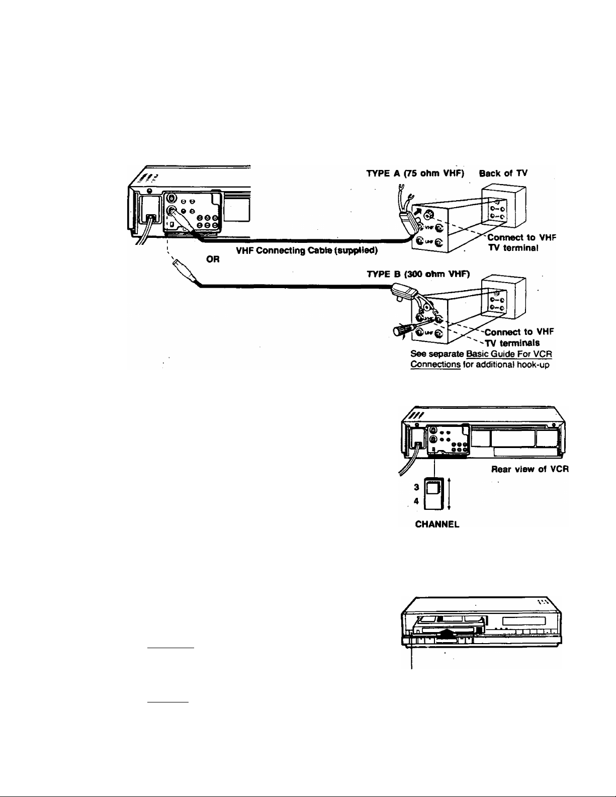
BASIC VCR TO TV CONNECTIONS
This is the only connection you need for Playback,
PLAYBACK CONNECTION
Back of VCR
SELECTION OF THE VCR OUTPUT CHANNEL (3/4)
Your VCR must control one TV channel permanently
B
just as a TV broadcast station does. To decide which
channel to use, select either channel 3 or 4 with the
Channel 3/4 switch on the back of the VCR. To avoid
local interference, the channel 3/4 switch position
you choose should match the number of the TV
channel that is not normally broadcast in your area.
If you have cable TV, select the channel that provides
the best reception. You can still watch your favorite
channels, see page 9 for normal broadcast channel
reception.
HOW TO INSERT AND REMOVE A VIDEO CASSETTE
• Be sure the VCR is plugged into an AC outlet.
To insert a video cassette
1, Hold the cassette, window side up, with the arrow
pointing away from you.
2. Gently push the cassette in until the pull of the
VCR loading mechanism takes the cassette into
position.
Auto Power
• Should the VCR Power be off, cassette insertion
will power the unit on.
To Remove a cassetie
1. Preso the EJECT Cutton.
Auto Eject
• If the VCR Power is OFF, a cassette can still be
ejected by pushing the EJECT Button.
2. Remove the cassette.
details.
EJECT Button
-3-
Page 5
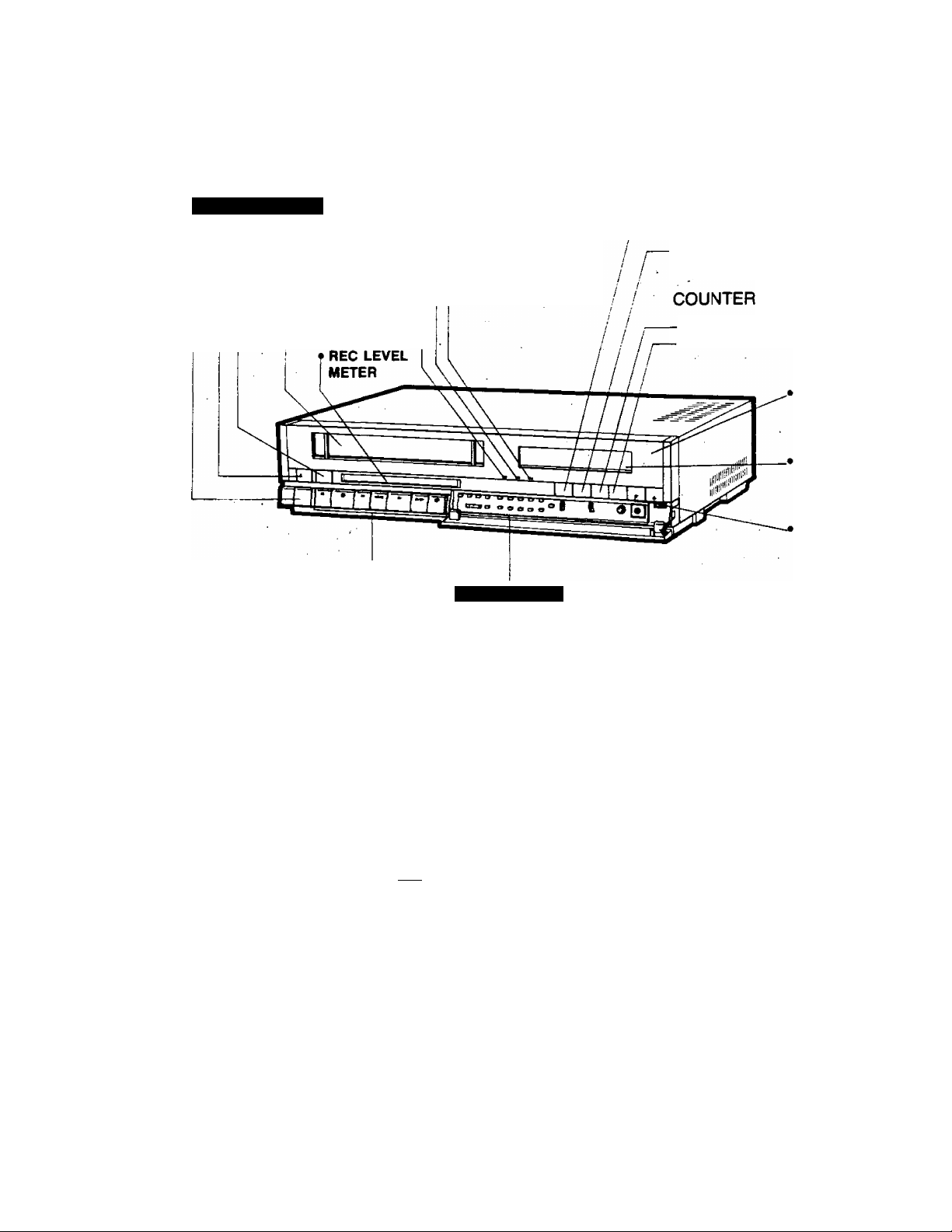
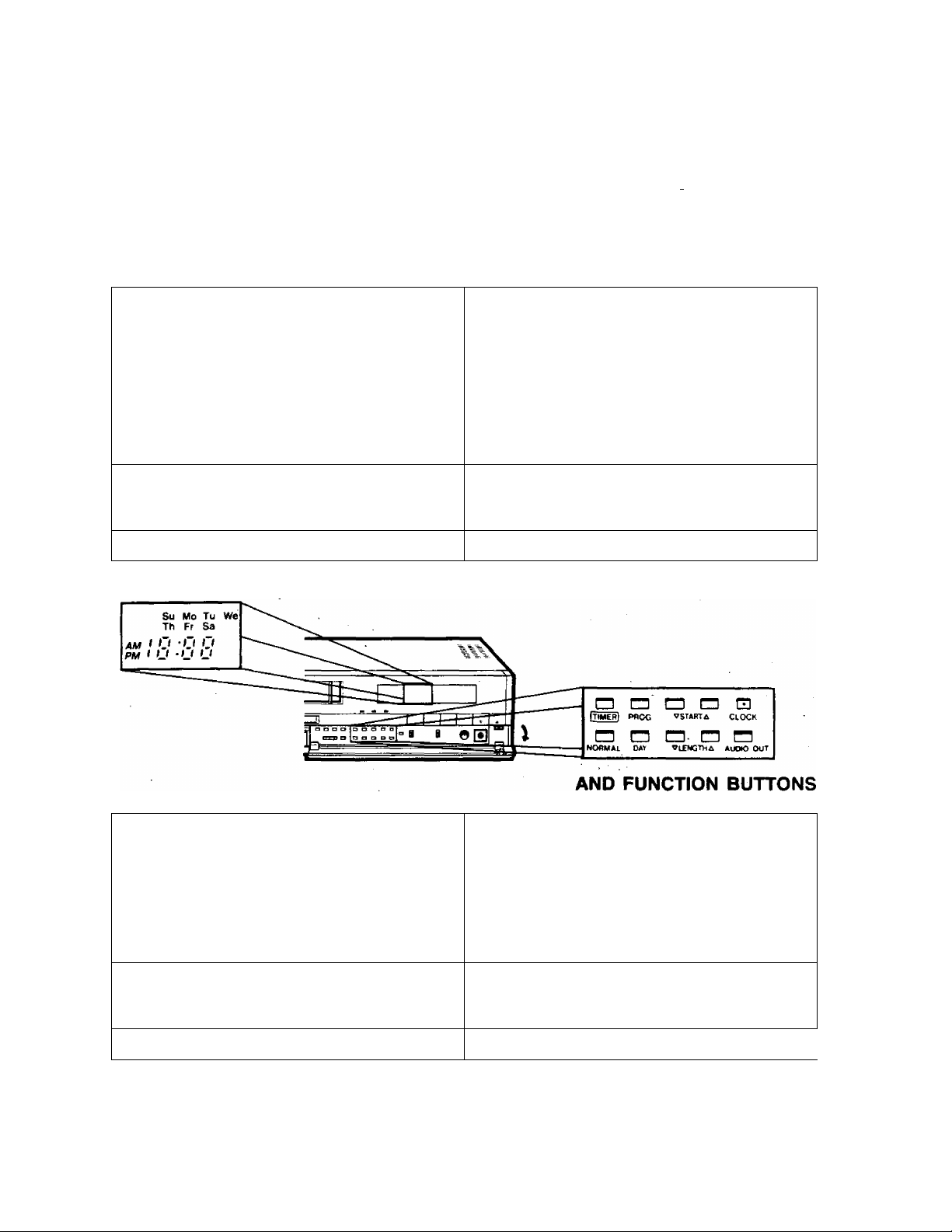
Description of controls
See “DETAILS” section for more information on each control, page 33.
PV:4760
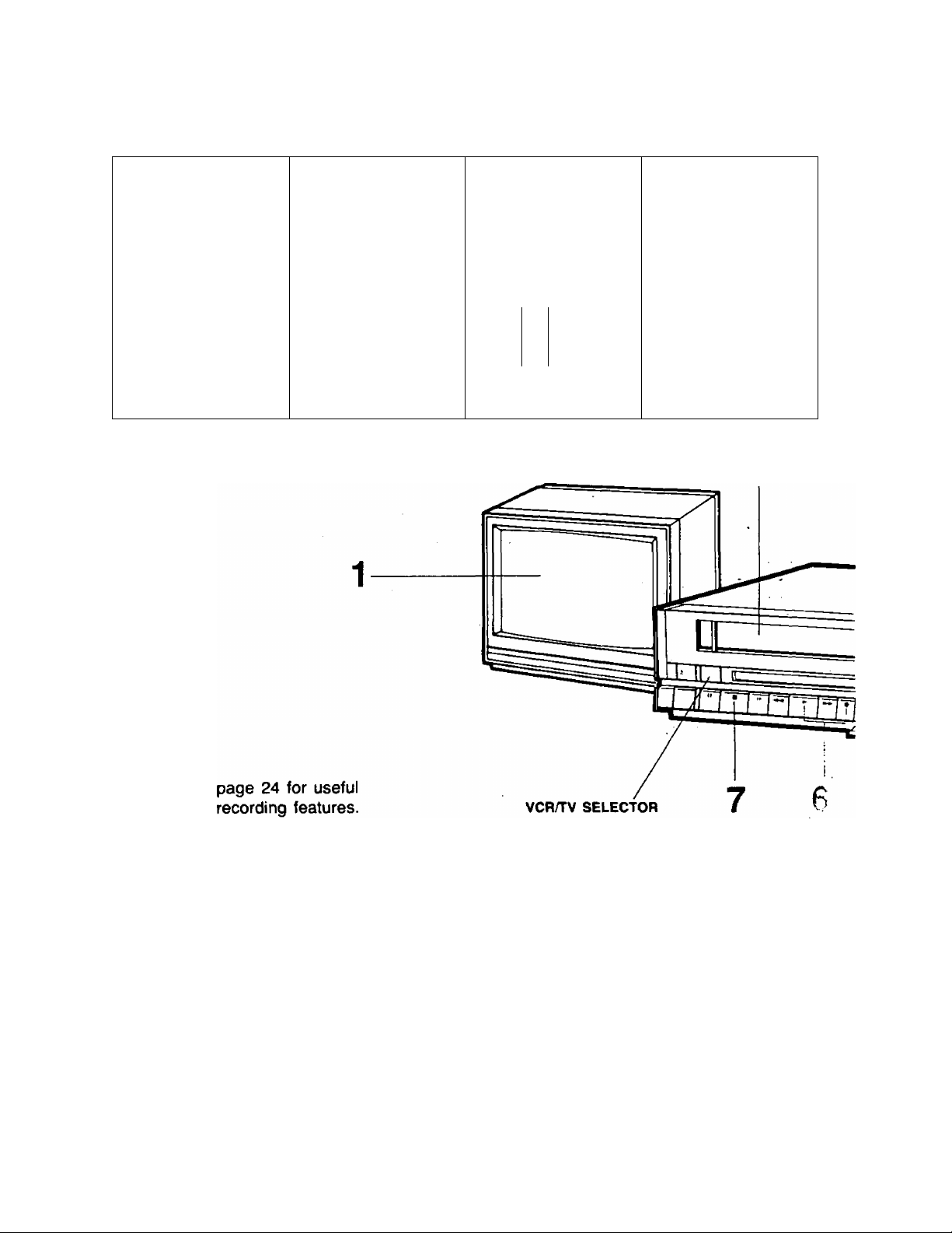
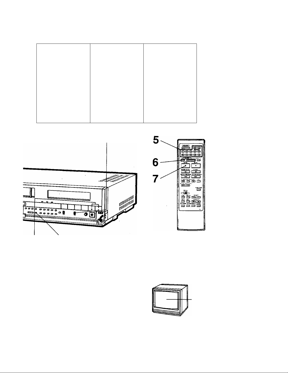
TOP and FRONT
POWER BUTTON
T EJECT BUTTON
• VCRHV SELECTOR
AUDIO Multi-Plex
BROADCAST INDICATORS
t MONO INDICATOR
STEREO INDICATOR
t AUDIO n
• CASSETTE
i COMPARTMENT
• OPERATION BUTTONS (See next page.)
CHANNEL MEMORY
• ADD/DELETE BUTTON-
• AUTO SET BUTTON-
• ANTENNA SYSTEM
SELECT BUTTON
• CHANNEL
UNATTENDED (TIMER)
RECORDING
• CHANNEL (UP/DOWN KEYS)
—• NORMAL BUTTON
TIMER BUTTON
• DAY BUTTON
MEMORY
BUTTON
r« LENGTH BUTTONS
INDICATOR
INNER PANEL
PROGRAM BUTTON
(UP/DOWN)
• START BUTTONS
(UP/DOWN)
ONE TOUCH RECORDING
STAND BY BUTTON
^ ONE TOUCH RECORD
(O.T.R.) BUTTON
« RESET BUTTON
« MEMORY BUTTON
WIRELESS
REMOTE
SENSOR
MULTI
FUNCTION
DISPLAY
CHANNEL
UP/DOWN
KEYS
INPUT SIGNAL
SELECTOR
I HEADPHONES
VOLUME CONTROL
ANT. AUTO ADD
WCWC STSTEm SET DLT
L14.IÍ Q
SPIED NOfkiAL OL'
• TRACKING CONTROL
(UP/DOWN)
• TAPE-SPEED SELECTOR
(SP/LP/SLP)
CLOCK ADJUSTMENT
• NORMAL Bim ON -
• DAY BUTTON
• START BUTTONS (UP/DOWN)-
• CLOCK BUTTON
--------------
----------------
ITIMERJ №nOG
■ V bw
CLCCK
C3n
,UOi> 0
-4-
■ -WP1
—>
'3^
r
LAVtl
• HEADPHONES JACK
AUDIO Multi-Plex
BROADCAST SYSTEM
-«INPUT AUDIO
SELECTOR SWITCH
-•MON* eUTTON
-• AUDIO OUT SELECT
BUTTON
Page 6
OPERATION BUTTONS
SPECIAL EFFECTS PLAYBACK
-• PAUSE/ST1LL BUTTON
SLOW BUTTON
REWIND/SEARCH ® BUTTON*
• FAST FORWARD/SEARCH @ BUTTON*—.
PLAY/X2 BUTTON
II
• STOP BUTTON
MULTI FUNCTION DISPLAY
• DIGITAL CLOCK/START TIME
• VCR/TV INDICATOR **VCR
• TIMER INDICATOR
• SPEED INDICATOR “SP”, "LP”, “SLI
• CASSETTE-IN
INDICATOR “ E3
FUNCTION INDICATOR
• PROGRAM NUMBER
FUNCTION INDICATOR SYMBOLS
These symbols and their combinations appear constantly or flash on the Multi Function Display to indicate the
current mode or operation of the VCR. See the chart below.
The current indications will be momentarily displayed on TV screen for a quick glance when you press the
Operation Button (see page 13).
STOP
—J
m
1
___ _
il
LJ (S iS OJi (li /PM f U * U Uf mh O * O 3foi U Uf
- ^
* NOTE; In playback mode, one press of the FF/SEARCH or REWIND/
SEARCH Buttons locks in the search function for viewing, press the search
button again to return to playback.
■ElI!-* ■ »■/SLPyVCW Ì2Ì St) Wo Tu VW / ,—L^i CATV
l!~! ffi i? iQ • o O O' h >-i -n rCJTTOl
EJECT
—
•
_ . (HE- 1w Th Fr Sa/BDI / JESBI f
-• RECORD BUTTON
PLAY REW
STAND BY INDICATOR
OTR INDICATOR
TIMER DISPLAY/
COUNTER DISPLAY
----
• CATV INDICATOR
CHANNEMNPUT SIGNAL
SELECTOR INDICATOR
MEMORY INDICATOR “M”
■
C T nn
J t u f
FF
►
r-l-
FF SEARCH DOUBLE SPEED PLAY
^ ^
0 i 0 u
/ f t t
SLOW ^
REC REC PAUSE REW SEARCH
►
P r
L L
►
o p
t c
DEW
>■
c 1 »■' ; !
J L. U UJ
.J 0 ! 1
OL IjJ
►
O! OU
t L. f t 1
per
T' L L
STILL
Oi ou
1 /„ / f I
CHANNEL MEMORY MODE
r 1 t
L ft
-5-
-4
P ! 1
n L IjJ
ot ou
/ L. / / /
FRAME ADVANCE
01 o u
1 t. ' 1 1
PROGRAM MODE
Op f'P,
1 » ' u u
Page 7
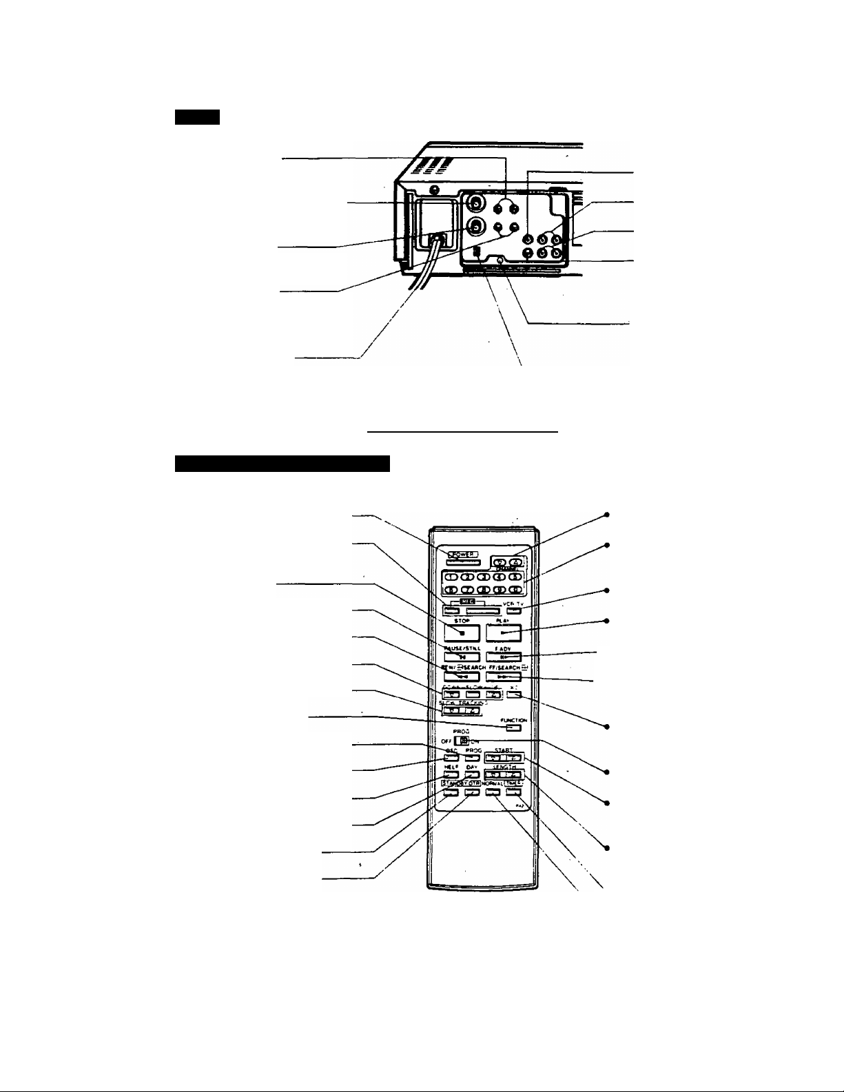
Description of controls
REAR
; ANTENNA CONNECTION
; «UNF ANTENNA
INPUT TERMINALS
(IN FROM ANTENNA)
• VHF ANTENNA
INPUT TERMINAL
(IN FROM ANTENNA)
• VHF ANTENNA
OUTPUT TERMINAL
(OUT TO TV SET)
• UHF ANTENNA
OUTPUT TERMINALS
(OUT TO TV SET)
• AC POWER CORD
See separate Basic Guide For VCR Connections for more hook-up details.
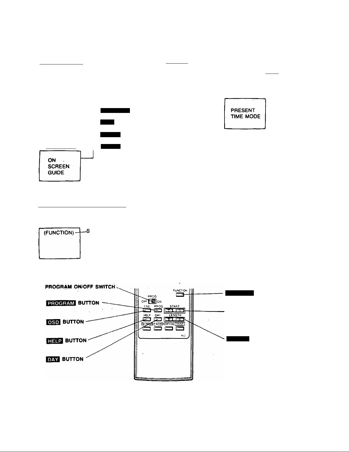
WIRELESS REMOTE CONTROL
Various VCR function controls are conveniently available with your Wireless Remote Control.
CONNECTIONS WITH
OTHER COMPONENTS
• VIDEO OUTPUT
• AUDIO OUTPUT
• AUDIO INPUT
• VIDEO INPUT
« VERTICAL LOCK
ADJUSTMENT CONTROL
PV-4760
CONNECTOR
CONNECTOR (UR)
CONNECTOR (UR)
CONNECTOR
CHANNEL 3/4 SWITCH
• POWER BUTTON
• RECORD BUTTONS
(TWO BUTTON ENTRY)
• STOP BUTTON
• PAUS&STILL BUTTON
• REW/SEARCH ® BUTTON
• SLOW-MOTION BUTTONS
• SLOW TRACKING CONTROL
• FUNCTION BUTTON
• PROGRAM BUTTON *-
• OSD BUTTON*
• HELP BUTTON *-
• DAY BUTTON*
• STAND BY BUTTON *-
• ONE TOUCH RECORD
(O.T.R.) BUTTON*
See page 42 for Battery Replacement caution.
* 'Tiese buttons wH: operate
w!,eii PROGRAM ON/OFF
SWITCH is ON.
CHANNEL UP/DOWN KEYS
NUMERICAL KEYS (0,1, 2, 3,
4, 5, 6. 7, e, and 9)
VCR/TV SELECTOR BUTTON
PLAY BUTTON
-• FRAME ADVANCE BUTTON
-• FAST FORWARD/SEARCH
® BUTTON
DOUBLE SPEED (X2) PLAY
BUTTON
PROGRAM ON/OFF SWITCH
START BUTTONS
(UP/DOWN)*
LENGTH BUTTONS
(UP/DOWN)*
• TIMER BUTTON*
* NOR^iAL BUTTON*
-6-
Page 8
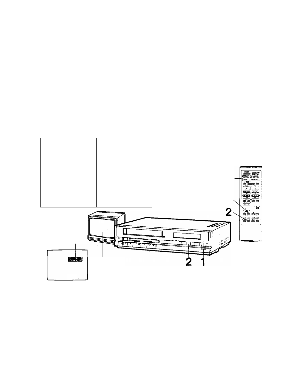
To PLAYBACK A PRE-RECORDED TAPE
See “Simple Playback Steps” in the Table of Contents on P.2 for all sections related to this operation.
You may also want to refer to the separate "Basic Guide For VCR Connections”.
1 2
Connect VCR output
to TV Antenna Input.
♦ P. 3 (PLAYBACK
CONNECTION)
Connect AC Power
cord to wall outlet.
3
Turn TV ON, select Insert cassette.
Channel 3 or 4 on the
TV.
Power comes on.
• If a cassette is already in
(Set to match the VCR
Channel 3/4 Switch,
details page 3.)
the VCR, press the
POWER Button ON.
4
SPECIAL EFFECTS PLAYBACK (BEST RESULTS AT SP & SLP SPEED)
TO RAPIDLY LOCATE A
PARTICULAR SEGMENT
Press the SEARCH Button tor
desired direction.
SEARCH SPEED
INSPabout 5 times normal
speed.
IN
about 17 times normal
speed.
SLP
s
Press SEARCH Button once
more for playback.
These special effects are activated during playback, during their operation the audio is muted.
TO VIEW A DOUBLE SPEED
PLAYBACK PICTURE
■ During playback, press the PLAY
Button again on the VCR.
■ Press PLAY once more to release the
tape from a doiArle speed playback.
• If the double speed playback picture
contains noise, adjust the TRACKING
CONTROL (UP or DOWN) to obtain
the best possible picture.
G3
-7
TO VIEW A STILL PICTURE
■ Press PAUSE/STILL Button. .
Press once more to release the
tape from pause/stiil mode.
Page 9
PV-4760
5
Press the AUDIO OUT
SELECT Button
according to desired # P. 37 (TO PLAYBACK)
audio channel.
(See page 25.)
Press PLAY Button.
6
7
Press STOP Button to
stop playback.
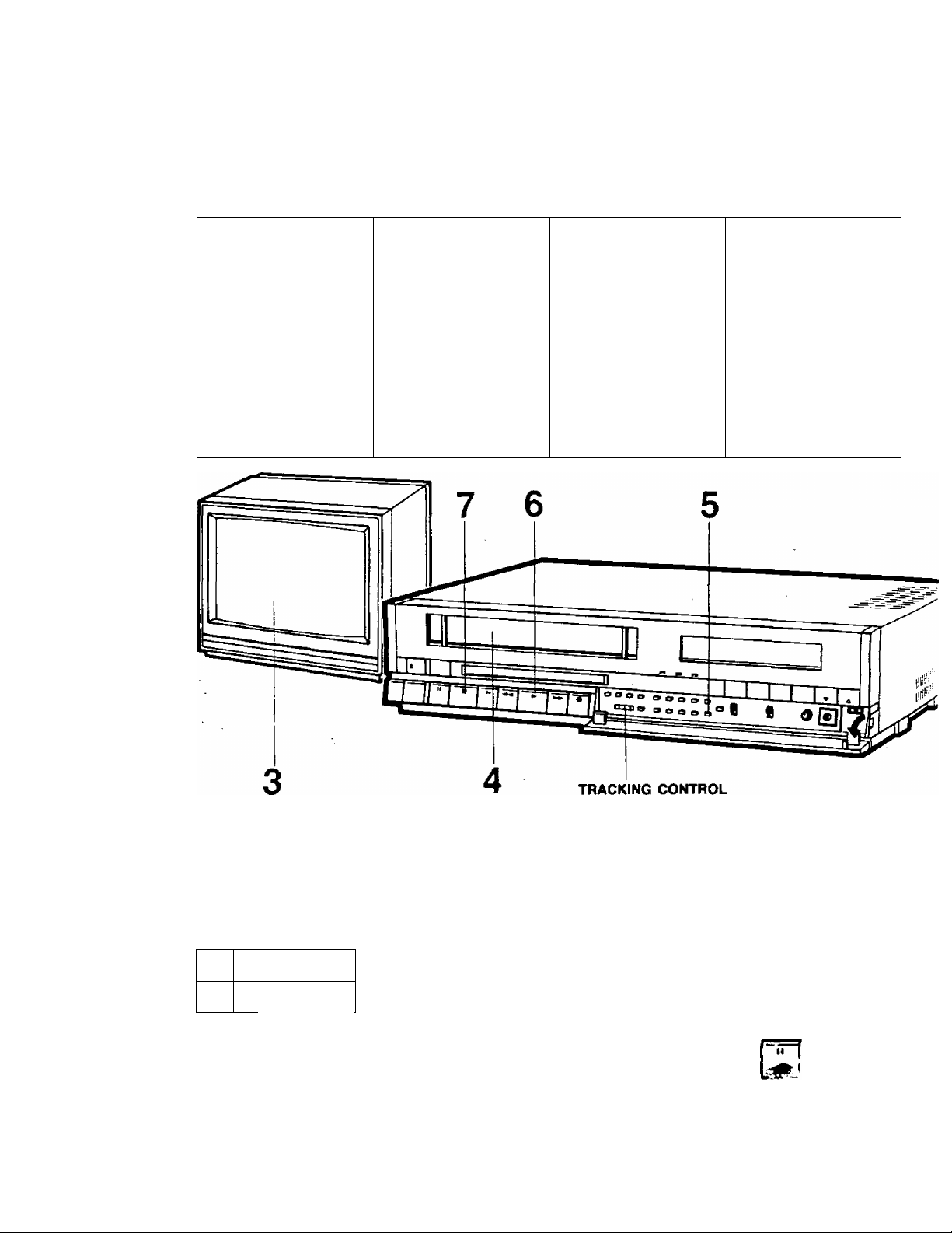
TRACKING CONTROL
0
A certain amount of "noise" interference may
appear in the picture image when a VHS video
tape recorded on one VCR is played back on a
different VCR.
You may adjust the TRACKING CONTROL (UP
or DOWN), on your VCR to minimize this noise.
The normal position is set when a cassette tape
is inserted.
TO ADVANCE A STILL PICTURE
■ During still mode, press the
SLOW Button (or the FRAME
ADVANCE Button on the Remote
Control).
• Franrte advance only operates
while viewing a still picture.
• The picture will slowly advance
frame by frame when this button
is held down.
» P.37 (TO PLAYBACK)
TO VIEW A SLOW PICTURE
■ During playback, press
the SLOW Button.
■ Press the PLAY Button
to release slow.
-8-
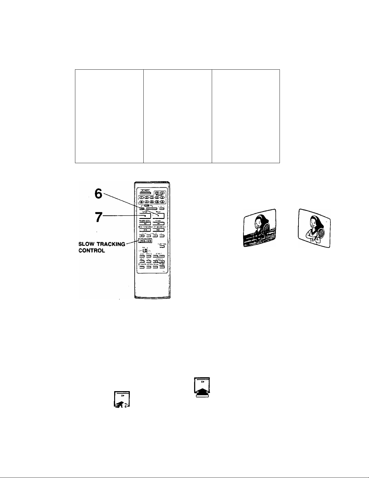
SLOW TRACKING CONTROL
SLOWTRACtaMQ
• In 8low4notion playback of tapes
recorded in SP or SLP, SLOW
TRACKING CONTROL on the
Remote Control can be used to
obtain the best possible picture.
The TRACKING CON fROl on the
VCR can alsr h i ui\-d (see abnv^,,
Page 10
Tv RECORDING PREPARATION
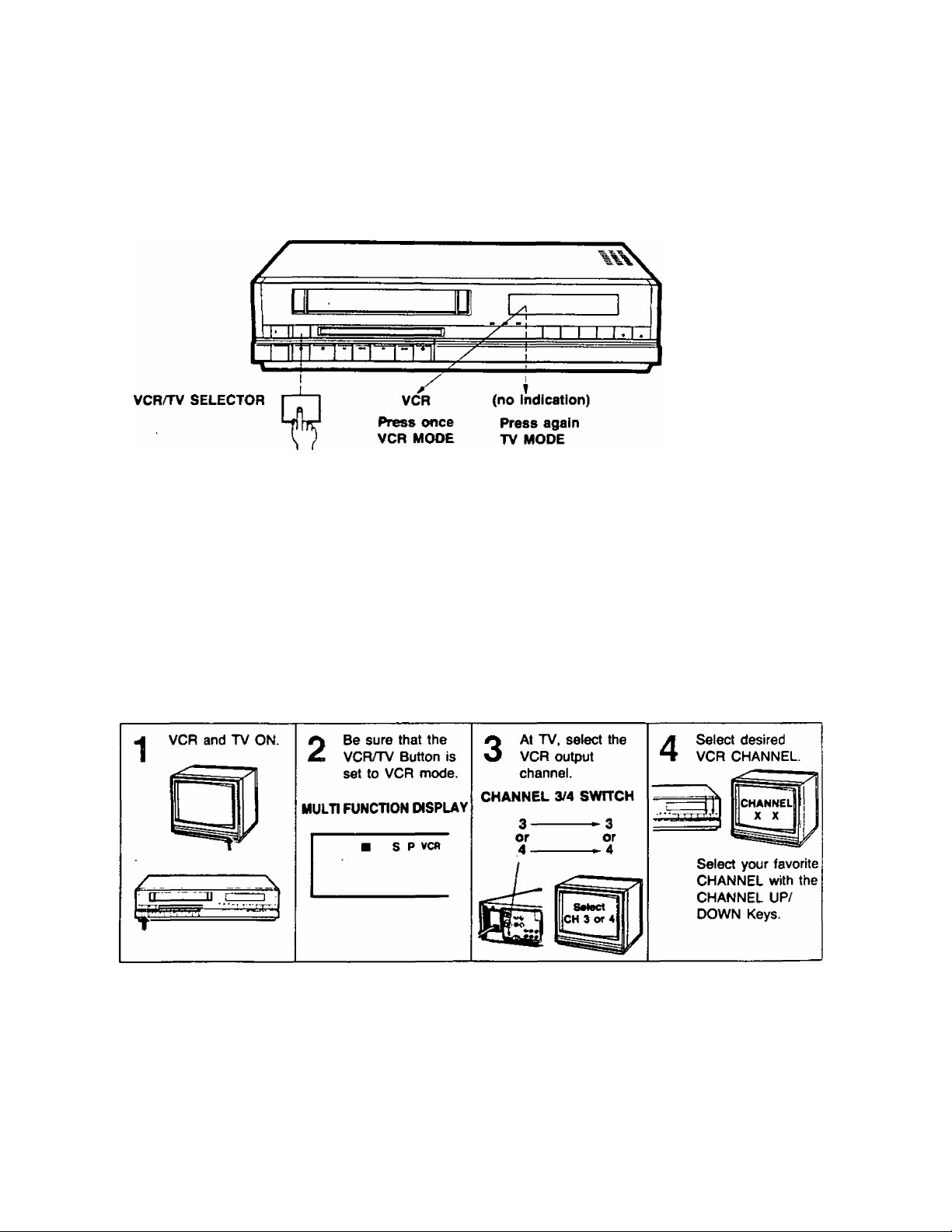
VCRH'V MODE SELECTION
After you have selected the TV channel number that matches your VCR Channel 3/4 Switch position, select the
"VCR” mode on the Multi Function Display (following the instructions below) to view your VCR Playback on TV,
or to monitor programs being recorded. Select the "TV” mode (“VCR" indication disappears) to watch a different
TV program while recording.
A. FOR VCR USE, BE SURE THE VCR POWER IS
TURNED ON AND THE “VCR" MODE IS
ENGAGED
To select the "VCR" mode, press the VCR/TV
SELECTOR Button.
Whenever the power to the VCR is pressed ON,
the VCR engages the VCR mode.
"VCR" appears on the Multi Function Display.
CHANNEL RECEPTION CHECK
AFTER MAKING THE RECORDING CONNECTIONS FOR YOUR VCR SHOWN IN THE "BASIC GUIDE FOR
VCR CONNECTIONS", USE THE FOLLOWING STEPS TO SELECT YOUR FAVORITE CHANNELS USING
THE CHANNEL UP/DOWN KEYS ON THE VCR.
B. FOR NORMAL TV USE, SELECT “TV” MODE
When "VCR" disappears from the Multi Function
Display, the VCR is in TV mode and the TV
returns to normal reception and operation.
MOW TO WATCH TV ONLY
,1. Turn VCR OFF.
12. Turn TV ON ard select the desired channel.
i 'V :) > i :
I • Whenever the VCR Power is OFF or the VCR/TV selector is not *r'. the “VCR" mode, all channel .: elect ion
for viewing is done at the TV.
-9-
Page 11
Clock adjustment
It's easy to set the clock as shown below. Besides being a convenient time display, the exact clock time is used.
for One Touch and Timer Recording. .
‘SU 12:00 AM’ will flash when the unit is first plugged in or after a power
interruption.,.
AM f ./•»(/(
FOR EXAMPLE, TO SET THE CLOCK FOR TUESDAY NIGHT “Tu 10:15 PM’
(Be sure the unit is connected to an AC power source.)
It -III /
PV-4760
______
Su
1 SET THE DAY
■
(a) Press the CLOCK Button ON to select
flashing time display.
Skip (a) if “Su AM 12:00" is flashing already.
(b) Press the DAY Button to change the day
display.
(a) (b)
^ ^ T ^
“ AM ( 7» -f’t '"i AM 1 ?
LOCATION OF GRAPHICS
( 1 *1 ( M ^ ^ 1 L -U U
y -\ ^
O SET THE HOUR
Hold In the START Buttons (UP/DOWN).
The time changes in 10-minute intervals.
'«V . 7u ^ Tu
AM f 'f~f f*' f
^ J L ^ ^PMy Li, -Lf^J ^
— •
Q SET THE MINUTE
A START CLOCK
■
Tap the START Buttons (UP/DOWN).
Quick taps will select the time in 1-minute
intervals.
Press the NORMAL Button only.
Press this button when the current time matches
the dock display.
\ ^ 1 'fu
1 /1 *n n -~^ r~ 1 n • t C ~
PM t U -U LI BM 1 U • f J ^
»If the c(o;k iisJiuation oveiturs the present time, fe^jeat thv^.-e ^ C|is ^Love.
Accurate setting of this dock will insuf^e accurate start of Unattended (Timer) Recordings.
-10- '
1 T( ■ t r
PM * U ^ t Zi
(Flashing s-^ps)
lu
Page 12
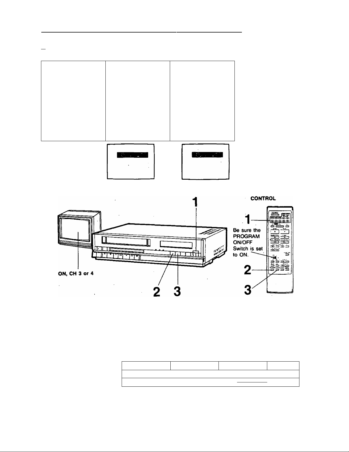
To RECORD A TV PROGRAM
See “Preparing the VCR for Recording“ in Table of Contents on P.2 for all sections related to this operation.
Use one of the connections described on the separate "Basic Guide For VCR Connections".
i
1 2
Turn TV ON, select
Channel 3 or 4 on the
TV.
(Set to match the VCR
Channel 3/4 Switch.)
Insert cassette with
accidental erasure
prevention tab in place.
POWER comes ON*.
Be sure that the VCR/TV
Selector is set to VCR.
* If a cassette is already
in the VCR, you may
need to press the
POWER Button ON.
♦ P. 39 (TAB)
4
Set INPUT SIGNAL Set TAPE-SPEED
SELECTOR TO
TUNER.
-TUNER
t
IMP! IT
LINE
AUDIO
iion
SELECTOR to SP, LP
or SLP.
4 P.37 (TAPE SPEED)
IF YOU WISH TO AVOID RECORDING UNWANTED MATERIAL
■ Press PAUSE/STILL Button to stop the tape temporarily.
* P. 37 (TO RFCOF.D)
Press this button again to release from pause mode, recording continues.
-11 -
Page 13
PV-4760
5
Select the desired
CHANNEL using the
CHANNEL UP/DOWN
Keys. to start recording.
Hold REC Button in
and simultaneously
press the PLAY Button
• If cassette erasure
prevention tab Is
missing, the cassette will
be ejected automatically.
» P.39 (TAB)
6
7
Press STOP Button to
stop recording.
* P.37 (TO RECORD)
IF YOU WANT TO WATCH ANOTHER TV PROGRAM WHILE RECORDING
■ Set VCRnv SELECTOR to TV.
• The "VCR” indicator and TV picture will change.
-TV
■ Select the CHANNEL to be viewed on the TV.
e
-12 -
-Select the CHANNEL
Page 14
OsD (ON SCREEN DISPLAY) INFORMATION
OSD. HELP & FUNCTION DISPLAY MODES
PROGRAM MODE
Timer Format
CURRENT
TIMER
PROGRAMS
Press
HELP MODE
Press
To check or
set programs
and use
OSD GUIDE
PROGRAM
DAY
START
length
* Place the PROGRAM ON/OFF
Switch to the ON position
to operate OSD and all
other Timer Buttons.
(UP/DOWN)
“ (UP/DOWN)
Current TV Picture
TV Image
NO OVERLAY
MODE
with
STOP REW FF PLAY REC REC/PAUSE etc.
Current operation selected
will be displayed.
Current VCR Status
OSD
MONITOR
FUNCTION MODE—,
(For overlays)
Press
OSD FUNCTION INDICATORS
The following on screen overlays will appear momentarily as a clear indication that one of the main functions
or a channel has been changed with the remote control or at the VCR.
TOP, PLAY, REC,
FF, REW, PAUSE,
STILL, SLOW, TIME, DATE,
CHANNEL INDICATION,
OTR (Whenever Preset OTR starts)
WIRELESS REMOTE CONTROL
“PLEASE SET THE CLOCK"
(indicates the clock needs adjustment)
FUNCTION
START
(UP/DOWN)
LENGTH
(UP/DOWN)
BUTTON
BUTTONS
BUTTONS
-13-
Page 15
One touch recording (otr)
The OTR function allows you to easily set start and stop time tor recording programs from the present time to
11:30 P.M. the following day. Pressing the OTR button will automatically start a recording and each following
press extends the recording in 30 minute increments. The OTR button may also be pressed to extend a recording
already in progress. When the OTR is completed, the VCR will automatically shut off.
OTR can be useful and convenient when you are interrupted or must leave while watching a program and wish
to record it for later viewing.
PV-4760
^ MAKE SURE THAT...
j • the clock is set to the present time.
; • Power Button is ON.
I
• a cassette with the erasure prevention tab in place is inserted,
j • desired Tape speed (SP, LP or SLP) is selected.
- • the following length and time selections are made within 5 second intervals. Otherwise the VCR will return
I to normal operating mode.
Q INSTANT Ò.T.R. If you wish to record instantly
1
Select the desired
-------------------------
Press the O.T.R. Button
------------------------------------------------------------------------------------------------------------
2
WIRELESS REMOTE CONTROL
CHANNEL
on the VCR.
as many times as you
need to set your desired
recording time.
Be sure the
PROGRAM ON/OFF
Switch is set
to ON.
current program
overlay
C rpp
J f uf
TIMER Display
[ 0:00 I----i*
(stand by mode)
p”! 'Cl i\ *
I L' -y t L.#
1 push
ON, CH 3 or 4
Pressing the OTR Button selects the OTR function; *'OTR", CHANNEL, and
Recording Length appear on TV screen, and the Multi Function Display. Each
press of the O.T.R. Button adds up to 4 hours recording time, in 30 minute
intervals, before automatic power shut off. If “End" is displayed, OTR continues
until the end of the tape is reached.
OTR recording length
1 push 1 push
0:30
]-
-14-
I 4:00 1^1 End I-—-
Page 16
One touch recording (otr) (continued)
m PRESET O.T.R. If you wish to delay the start time
1 2
Select the desired
CHANNEL
on the VCR.
3
Press the STAND BY Press the O.T.R.
Button
to set the desired start
time of One Touch
Recording.
Button
within 5 seconds after
selecting the start time
to select the length of
recording as shown in
Instant O.T.R. step 2.
WIRELESS REMOTE
• "STANDBY” and the start time appear. The start time may be selected on
the hour and the half hour, beginning with the next 30 minute period and
any additional 30 minute time periods may be selected up to 11:30 PM of
the next day.
For example:
Present Time
8:03 AM
8:33 AM
-15-
Start Time
8:30 AM
9:00 AM
Additional Units
9:00,
9:30,
in nn ....
9:30,
L .
............
(Next Day)
- , 11:30 PM
11 ■'in PM
Page 17

PV-4760
EXTENDING CURRENT RECORDING TIME
Any currently running O.T.R. may be extended beyond the programmed recording time period by pressing the
O.T.R, Button as shown in Instant O.T.R. step 2.
INTERRUPTING AN O.T.R.
Pressing the O.T.R. Button, so that the timer display reads ‘‘0:00", will turn the VCR off in about 5 seconds, or
pressing the STAND BY Button and O.T.R. Button on the VCR will shut the VCR off immediately.
For example:
To Stop O.T.R.
during recording
O.T.R.
Button
em
n -n n
U 'U u
Press again.
about 5 seconds later O.T.R.
stops (Timer display goes off)
or press STAND BY Button
together with O.T.R. Button on
the VCR to shut off VCR
immediately. (See above
“INTERRUPTING AN O.T.R.
RECORDING.’’)
Press once,
Normal Operation Display
Here, O.T.R.
recording is . / .p/
in progress. # ./_/ fj
35 minutes later
rtîîH
n • */ /“
U 'L J
flashes.
24 minutes later
Kffi}
n n I
U 'U f
To make the O.T.R.
time longer
O.T.R.
Button
[•IL3
n •/■/ n
U 'U u
Press once, . Press again.
“Iniu" flashes.
Press 'twice
more.
t -n n
* U
1 minute later
O.T.R. stops
(Timer display goes off)
NOTE: .
For programming daily and weekly programs see timer recording section beginning on following page.
-16-
1 hour additional recording
Page 18

Timer recording
Your VCR will follow a schedule for unattended recording of those "hard to catch” programs you'd like to see.
-With the TIMER feature it’s easy to make a schedule of 8 fully independent programs for automatic recording.
You cevi plan 7 independent one time recording events any time within a 3 week period.
Each of the 7 independent program positions also allows its own series of DAILY recording events to take place
at the same Time, Recording Length, and Channel. In addition an 8th program position allows a series of WEEKLY
recording events to take place on the same Weekday, at the same Time, Length, and Channel.
Both DAILY and WEEKLY series recording plans may continue for the full length of the cassette.
The Remote Control has an OSD Button that activates the On Screen Display with a format that shows all current
programs set and also includes a help function, for convenient Timer Programming.
Repeat the steps shown here for each recording plan you want to add to your schedule.
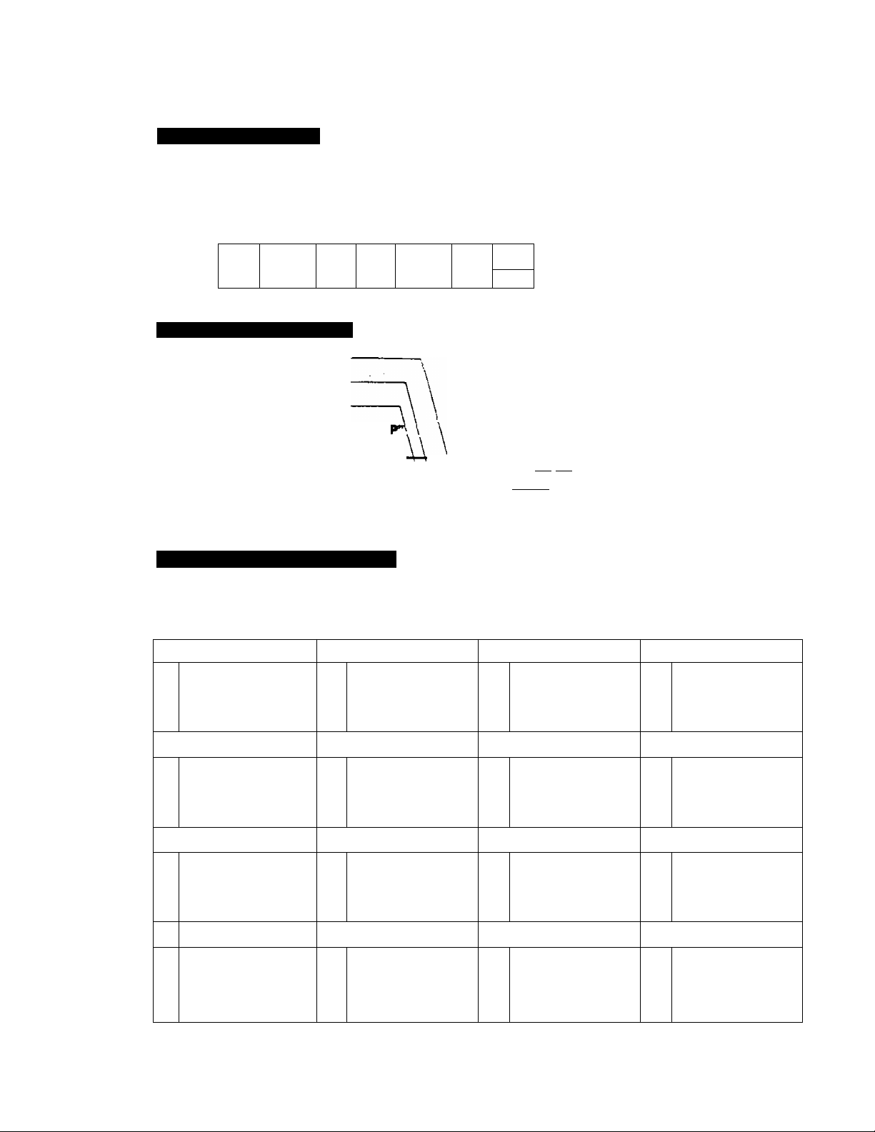
For each program number your VCR Timer needs to have:
TIMER SETTINGS FOR EXAMPLE
(1) Program number
(2) Day, week
(3) AM/PM Time to start
(4) Length of program recording
I (5) CHANNEL position to select
P Dif. START LGTH CH
1 FRl Pl2 : 00 1 :1 5' n
2
3
4
5
6
7
(1) Program number 1
(2) this Friday
12:00 PM (noon)
(3)
1 hour, 15 minutes
<4)
Channel 11
(5)
Present tiine is Saturday 11:30 AM..
For procedure see p. 18.
BEFORE
SETTING TIMER
• TV ON, CH 3 or 4.
• VCR Power ON.'
• Insert cassette,
• VCR/TV Selector to VCR:
• Select desired recording
speed (SP, LP, SLP).
• Is Clock correct?
• Is there enough tape?
• Is recording tab on cassette
in place?
• For timer programming
assistance refer to P. 21.
The VCR uses program numbers to display and locate the recording plan you key in. Once the VCR has that
recording information, a complete recording plan is displayed after its program number.
,Be sure the
CHANNEL .
/ PROGRAM ON/OFF
Switch is set
to ON.
!d'3jc :
„ail '
- PROG
OFF CD ON
OSD ■pROG''
HELP ETAY
BTART
LENGTH ■
■ h 1
[STANDBY OT^NORMALi TIMER j
(1) PROGRAM
(2) WEEK, DAY
(3) TIME (4) LENGTH (5) CHANNEL
NUMBER
-17-
Page 19

PV-4760
ON SCREEN DISPLAY
Set PROGRAM ON/OFF Switch to ON.
1
This switch enables the use of timer recording
buttons.
Press OSD Button ON, on the Wireless Remote
Control.
Program number format and any previously set
programs will be displayed on TV.
Skip this step when you are not using OSD.
TV DISPLAY
R 01* START LGTH CH »0^01* START LGTH CH
1 - t .«Al All:30 0:00 36
г
3
4
i
S
7
w
WIRELESS REMOTE CONTROL
off! ШЗ
2
8
1
9
I STANDBY Off^NORMALi TIMER I
3
PROG
ON
OSD ЩОС ,ST/^
HELP DAY
Q Ф
a a s
SELECT PROGRAM NUMBER
Press PROGRAM Button.
“1” flashes.
You can rww select the program number to be
preset.
• Press the PROGRAM Button once each time
you want to advance to the next program
number.
3
4
i
t
7
tt
CHANNEL J
4,
a Г-7И
6
10
SET THE START TIME (DAY)
Press DAY Button to set the
day.
3
The present day will be the first day
of ttre first week.
Therefore, if you are setting a day
more than 7 days in advance, the
symbol for the second, or third week
"2", or “3” will appear on TV screen.
START 1GÌH CH
*4:30 0:»0 36
*?
SET THE START TIME (HOUR)
Hold START Buttons (UP/
DOWN) in to set the hour.
(The time changes in
10-minute intervals.)
• Be sure to check №e AM,
PM indicators.
START LGTH CH
A11 :30 0:00 3(
- 18-
SET THE START TIME (MINUTE)
Tap START Buttons (UP/
DOWN) quickly to set the
minutes.
START IGTH CH
-I^Hl P1*:00 0:00 36
Page 20

Timer recording (continued)
SET THE RECORDING LENGTH
Press LENGTH Buttons (UP/DOWN) to set the
recording length.
6
(The recording length may be selected from 0:00
to 8:00 in 15 minute units.)
TV DISPLAY
vPrOiw sTAm iGTH CM
^1-fRl P12:00 0:D0 »
4
5
8
7
WIRELESS REMOTE CONTROL
SET THE CHANNEL TO BE RECORDED
Press CHANNEL UP/DOWN Keys to set the
channel.
• If your VCR is connected to a cable system
through a cstole converter box, the VCR
CHANNEL is set to the output channel of the
converter box and the channel to be recorded
is set on the converter box selector.
„Py0(« STMT IGTH CM
- 1^Ht Pii;06 liti 36
3
4
5
e
7
W
CD C D
CHANNEL
4, 5
FOR ADDITIONAL PROGRAMS
Press PROGRAM Button to
select the next program by
8
repeating step 2 and then
repeating steps 3~7.
P 0(W START IGTH Cm
AFTER THE TIMER RECORDING HAS TAKEN PLACE
■ Set TIMER Button OFF.
• Unit will return to normal operation.
P)i:06 1:15 11
-J^AI All ;30 0:60 31
4
i
«
i
*
RETURN TO NORMAL DISPLAY
Press OSD Button to n^ease
ON SCREEN DISPLAY mode
and return to reception on TV..
When OSD is not being : ,
used: (If step 1 is skipped)
Press NORMAL Button.to
return to normal mode.
current
program
-19-
6
10
TIMER SET MODE
Set TIMER Button ON and
turn TV OFF.
10
- . • TIMER Indicator “ nTi^TIl ”
appears.
• There is no need to press
the REC and PLAY
; Buttons.
vrvy if the cassette tab is
missing, tape will be
. ejected and the
CASSETTE-IN Indicator
“ CD ** and “ nm " will
flash as a warning that the
cassette tab is missing.
NOTE: When not using the OSD and HELP
buttons place the PROGRAM ON/
OFF Switch in the OFF position to
prevent misoperation.
Page 21

EXAMPLE OF A FULL SCHEDULE OF TIMER RECORDINGS
The patterns-represent a possible schedule of recordings.
1. DAILY (Comedy)
2. rrttn ONE TIME (Movie)
3. ONE TIME (Travelog)
A. iAAAAi ONE TIME (Election Watch)
5. DAILY (News)
6. NO SETTING
7. NO SETTING
8. ■■■ WEEKLY (Cooking)
1st Week
TIME AM
OF
2nd Week
3rd Week
4th Week, etc
Daily or
Weekly Recordings
will continue to
end of tape.
DAY PM
AM
PM
AM
PM
Sa Su Mo Tu We Th Fr
■ az:
kWvVL'
-m"-'
[ZHz:
PV-4760
1
ssssw
Every-Day and Every-Week Recording will continue over the fuli-length of a cassette as long as the TIMER
Button is set to ON.
DAILY SETTINGS
For the same recording time
each day.
1. Press PROGRAM Button
to select desired number.
2. Press DAY Buttori until
“DAY" is displayed.
TO CHECK THE PROGRAMS
(If Timer mode is set, press TIMER Button to release it.)
Push PROGRAM ON/OFF
Switch to ON.
Press OSD Button.
All plans set for recording will
appear on the TV Screen.
After checking the programs,
be sure to reset the TIMER Button
for Unattended Recording.
TO CLEAR PROGRAMS RESET THE RECORDING LENGTH TO “0:00”
Use the PROGRAM Button and LENGTH Buttons (UP/DOWN) as in steps 6 then press the OSD Button to
return to normal mode.
P 01» START LGTm Cm
1 day A'. 1 :30 0:00 30
i
3
b
6
7
A
Continue with steps 4-10 shown on
previous pages.
P 0/* STitRT LGTH CW
1 Ffti P12:0C 1:15 n
! SU! P iiOS 0:30 36
3
5
6
-20-
ONE WEEKLY SETTING
For the same recording day
and time each week.
1. Press PROGRAM Button
until "W” begins flashing.
2. Press DAY Button to set the
day.
If a Timer Recording is in
progress, that program line will
be flashing.
p Oi* STAflT LGTr*
1
i
3
5
E
-^.:PR Ai 1:30 0:00 36
<>'tJ6t6‘9TWT“'WV CV ■,
3
5
6
Vt
Page 22

Following the program guide
If you would like a guide, you may use the HELP button on the Remote Control unit to assist you in programming
unattended recordings. The help mode will offer you short prompts, until you have completely programmed a
Timer Recording. . -
CURRENT PROGRAM MODE ENTER HELP MODE
^ Press the OSD Button.
Press the HELP Button.
2
This displays the OSD timer program mode. Follow the program guide on TV screen.
(See page 18.)
P O/W START LGTH CH
1
2
3
4 .
5
6
7
W
f t f===i return to
I I Normal mode
NORMAL MODE
SELECT PROGRAM NUMBER
PROGRAM NUMBER
P D/W START LGTH CH
1
FOR PROGRAMMING
(PUSH PROG BUTTON)
(CHECK TAPE AND
RECORDING SPEED)
PROGRAM
BUTTON
OSD BUTTON
HELP 'DAY LEM
HELP BUTTON
DAY BUTTON
SlAfriDBYQT^NORMALi TIME^[
C3
SET THE START TIME (DAY)
DAY
PBOG
rm]oN
Osb\.PROG . _
START
BUTTONS
LENGTH
BUTTONS
TIMER
BUTTON
TITLE
SELECT
PROGRAM,
CURRENT
TIMER
GUIDE
NEXT STEI
;P^D/W START LGTH CH
J-FR1 A 8:25 0:00 23
P: PROGRAM NO.
SELECT PRO.NO.
BY PRESSING PROG
BUTTON.
(PUSH HELP BUTTON)
-21 -
D/W START LGTH CH
A 8:25 0:00 23
0/W: DAY AND WEEK
SET DAY AND WEEK
BY PRESSING '
DAY BUTTON.
(PUSH HELP BUTTON)
Page 23

PV-4760
SET THE START TIME (HOUR & MINUTE)
g HOUR & MINUTE
P 0/W START LGTH CH
-y-M02 A 8:25 0:00 23
START;REC.START TIME
SET REC.START TIME
BY PRESSING START
UP/DOWN BUTTON.
(PUSH HELP BUTTON)
SET THE RECORDING LENGTH
0 LENGTH
^R.O/W START LGTH CH
-^(;-M02 P1 1 :30 0^ 23
LGTH: REC.LENGTH
SET REC.LENGTH
BY PRESSING LGTH
UP/DOWN BUTTON.
(PUSH HELP BUTTON)
EXIT HELP MODE
FOR ADDITIONAL PROGRAMS
8
Push PROGRAM Button to select the next
program.
SET THE CHANNEL TO BE RECORDED
CHANNEL
P D/W START IGTH CH
-;|C-«02 P1l;30 2:30 23
CH;TV CHANNEL
SET TV CHANNEL
BY PRESSING CH
UP/DOWN BUTTON.
(PUSH OSD BUTTON)
-22-
RETURN TO NORMAL VIEWING MODE
Push OSD Button for release of ON SCREEN
DISPLAY mode to return to CHANNEL reception
on TV.
SET TIMER TO STANDBY MODE
Push TIMER Button.
• Go to step 10 on page 19 to set TIMER for
TIMER RECORDING.
FOR ADDING PROGRAMS
(PUSH PROG BUTTON)
FOR TV VIEWING
(PUSH OSD BUTTON)
FOR TIMER MODE
CHECK TAPE AND SPEED
(PUSH TIMER BUTTON)
Page 24

On screen display of “functions
99
The On Screen Display makes the current VCR mode intormation clearly visible on your TV. Use the Remote
Corrtrol to show the following display, by pressing the FUNCTION Button.
WIRELESS REMOTE
CONTROL
FUNCTION
Button
OVERLAY MODE SELECTION
Function
press
Button
TV
SCREEN
(with current
TV picture)
[NO OVERLAY MODE]
The current program
has no overlay.
Check before operation:
• Be sure the VCR Power is ON.
I «Turn TV ON and select CH 3 or 4.
• Select VCR/TV Selector to VCR.
OPERATION
press
MEMORY 9876
Function
Button
REC SP Ш
Си 03
(with current
TV picture)
[FUNCTION MODE]
Digital Clock—
Display
press
Function
Button
WON Awii:30
(with current
TV picture)
[PRESENT TIME MODE]
/An overlay like the ones shown here appears when each of these conditions and VCR functions are selected.
Mode Overlays*
(with current program)
STOP SIP ca
(Ч)
STOP mode
Tape Speed
Indicator
EJECT mode
REW mode
Memory
Indicator
~V
FF mode
Eject the cassette
CASSETTE-IN
Indicator
\
PLAY mode
in stop mode.
CATV Indicator
НЕС ISLP Ш
ICATVOJ
MEMORY lire
REC mode
CH Display
PAUSE SLP ES
-----
СИ
MEMORY «719
RECORD/PAUSE mode
Input Signal
Selector Indicator
______
L
\
ЯЕС ca
MEMOS' I'i'i
LINE mode
(See page 34.)
(See Multi Function Display on page 5 for details.
NOTE:
• During Special Effects Playback the overlay of the Function Display will disappear.
* See CASSETTE-IN INDICATOR description on page 34.
-23-
Counter
Number
se Ш
C- Of
9f'f
Page 25

Useful features for recording PV-4760
FINE-EDITING
These Fine Editing steps will minimize visual noise when you wish to start recording a segment after pressing
the STOP Button.
Press PLAY Button.
1
Press PAUSE/
STILL Button.
Hold REC Button
in and press PLAY
Button.
Press PAUSe
STILL Button.
S
View the picture on TV.
Stop the tape where you
wish to continue recording.
Pressing these two buttons
down together puts the
VCR into the record/pause
mode.
Recording will resume.
RESET
BUTTON BUTTON BUTTON BUTTON
HOW TO LOCATE RECORDING PROGRAMS ON A TAPE
Use the tape counter
Press REWIND Button.
MEMORY
Press RESET Button.
1
Rewind the tape to the starting
point.
Press the RESET Button so that the
tape counter shows “0000".
-PLAY
BUTTON
This will help you locate the
recorded program you want to view
without lengthy reviews of the tape.
Use the counter memory
Press RESET Button.
1
Before starting a recording or
playback, press the RESET Button
so that the tape counter shows
“0000".
Press MEMORY Button.
"M" appears on the Multi Function
Display and memory mode is set to
stop at “0000" counter indication.
-24-
During fast forward or rewind the
tape will stop automatically at the
position where “0000" has been set.
Page 26

Simulcast (Stereo) recording and playback
This feature enables you to record Stereo Audio from your FM Receiver from many TV broadcasts, such as
MTV (Music TV), if the TV program is also being simulcast in FM stereo.
OPERATION
PREPARATION
• TV ON. CH 3 or 4.
• VCR Power ON.
• Insert cassette.
• VCR/TV Selector to
VCR.
• You can select the desired audio channels by following the AUDIO CHANNEL SELECTION description on
page 26.
STEREO PLAYBACK
Stereo playback operations are the same as "TO PLAY BACK A PRE-RECORDED TAPE”. (See page 7.)
Set INPUT SIGNAL
1
SELECTOR to AUDIO
2 CH.
LINE
i-TUNER
2CH
Set TAPE-SPEED
SELECTOR to SP. LP,
2
or SLP.
Hi-Fi AUDIO HD SOUND SYSTEM
Your VCR has a new Hi-Fi AUDIO Sound System with several improvements. Its audio frequency response is
flat over the entire audible range, and great strides have been made in the dynamic range and signal-to-noise ratio.
RECORDING WITH Hi-Fi ÀUDIO SOUND
Both Hi-Fi AUDIO and NORMAL AUDIO sound are automatically recorded during regular video recording.
(It is not necessary to use the AUDIO OUT SELECT Button.)
W-X
-------
REC LEVEL METER
AUDIO OUT SELECT BUTTON
-25 -
Page 27

PV-4760
O Select the desired /1 Adjust STEREO
O CHANNEL by
using the
CHANNEL UP/
H TUNER or
RECEIVER for
high-quality
DOWN KEYS. sound.
* » .M VIDEO IN*
* If your TV has VIDEO IN
terminal, you can connect
this line to receive a better
quality picture.
WHEN YOU USE A HEADPHONE
Cable
(not supplied)
C Hold REC Button
w In and press PLAY
Button.
Cables
(not supplied)
For monitoring
and playback
STEREO TUNER or
RECEIVER
Adjust your Headphone’s stereo playback sound by using the Headphones Volume Control, next to the
HEADPHONES Jack (M3), on your VCR.
PLAYBACK WITH Hi-Fi AUDIO SOUND
AUDIO CHANNEL SELECTION
Press the AUDIO OUT SELECT Button to select the type of audio sound and channel
combination you desire to monitor or playback.
Both left and right channels play back recorded signal with Hi-Fi AUDIO
SOUND
------
Only signal recorded on left channel plays back with Hi-Fi AUDIO SOUND
SOUND
-26 -
ii lilS Hi~Fi [H]li 11
REC LEVEL METER
-E Hi-Fi
E Hi-Fi
.p irJ Only signal recorded on right channel plays back with Hi-Fi AUDIO
-Hi-Fi s
^-No display- For playback with NORMAL AUDIO (mono) SOUND
• Other operations are the same as “TO PLAY BACK A PRE-RECORDED TAPE’
(page 7).
Page 28

Audio Muiti-piex broadcast system
The enjoyment oi Audio Multi-Plex Broadcasting is yours, even when you are watching a mono sound TV, by
using stereo AMP and speakers or a Headphones. You may select the type o1 broadcast and sound track you
wish to record with a single switch.
CONNECTIONS
AUDIO n INDICATOR
STEREO INDICATOR
MONO
mono Mereo speaker
speaker TV TV
1
t—
OR
------
STEREO AMP
monitor TV or RECEIVER
OR
.
m
-
---7
0
INDICATOR
REC LEVEL
FRONT METER
\
AUDIO OUT
SELECT BUTTON
PROGRAM INDICATORS
The various combinations ot Program Indicators described below will light when broadcast signals are received.
The type of broadcasts possible are arranged down the left side of the chart on the next page.
I
----
fV STEREO
MONO
ISTEIpEO AUDIO n I
INPUT AUDIO
SELECTOR SWITCH
------
1
HEADPHONES
JACK
When a program in stereo is received, the STEREO Indicator
lights up.
When a second audio program is received, the AUDIO H
Indicator lights up.
VIDEO OUT
\
AUDIO OUT (UR)
a
Press
MAIN
-SAPI
~SAP2
-• When a stereo and second audio program is received, both
STEREO and AUDIO ^ Indicators light up.
— ' Lights up when the MONO Button is set to MONO. When no
indicators are lit a mono broadcast is being received.
RECORDING OF AUDIO II OR STEREO A AUDIO fl BROADCASTS
STEREO, AUDIO D or STEREO & AUDIO II Broadcasts are recorded on the cassette in
Hi-Fi and NORMAL sound simultaneously, when the STEREO or AUDIO D Indicator is on.
Use the recording operations in “TO RECORD A TV PROGRAM" on page 11 with the
addition of the desired recording settings as shown on the next page.
USING THE MONO BUTTON
If there is noise and the STEREO or AUDIO D indication is intermittent it may be desirable
to set the MONO Button to the MONO position to improve sound quality.
MONO Indicator lights up on the front Panel. You may set this MONO position with
CHANNEL MEMORY (see page 32).
NOTE:
• This will also function during Timer Recording or One Touch Recording.
• Set this button to desired position before Timer Recording.
-27-
Page 29

RECORDING TRACK SELECTIONS WITH INPUT AUDIO SELECTOR SWITCH
PV-4760
XaUWO SELECTORS
BROAOCASrXPOSmON
X* «OHO BUTTON
MONO
BROADCAST
STEREO
BROADCAST
AUDIO n
(second
audio)
BROADCAST
STEREO
+
AUDIO n
BROADCAST
TRACK
NORMAL
AUDIO TRACK
(MONO)
Alt positions
MONO MONO (MIXED)
MAIN
SAP1
• SAP 2
MONO
MAIN
SAP 1
SAP 2
MONO
MAIN
SAP 1
MONO
MONO (MIXED)
MONO (MAIN)
MONO (AUDIO n)
MONO (MAIN)
HI-FI AUDIO TRACK
(STEREO)
L CHANNEL
MONO ■
MONO (MIXED)
STEREO
MONO (MAIN) MONO (MAIN)
MONO (MAIN)
MONO (AUDIOn)
MONO (MAIN) MONO (MAIN)
STEREO
MONO (MAIN)
R CHANNEL
MONO
MONO (MIXED)
MONO(AUDIOn)
MONO (AUDIOD)
MONO (AUDIO n)
Press
SAP 2
MONO (AUDIO D)
____^----*-------------
MONO (AUDIO n)
-------------A------------
MONO (AUDIOn)
------------i-------------on tape
PLAYBACK {OR MONITORING DURING RECORDING) OF STEREO AND SECOND AUDIO SOUND
AUDIO CHANNEL SELECTION
■ Press the AUDIO OUT SELECT Button to select the type of audio sound and channel
combination you desire to monitor or playback. The Record Level Meter indicates the
selected mode. (See page 26.)
• Other operations are the same as “TO PLAY BACK A PRE-RECORDED TAPE’’ (page 7).
-28 -
Page 30

AMERA RECORDING
Your VCR can be used with a camera and optional power supply (PK-A789S) to make your own recordings.
CONNECTION
Make the connections below before turning the VCR and the power supply ON,
1 2 3
Insert cassette.
VCR Power comes
on automatically.
I Refer to the Operating Instructions for the camera about adjustments and operating procedures.
TO MONITOR ON TV
The signal being recorded can be monitored on a TV.
The antenna connections on the VCR may remain connected when using a camera.
■ Turn TV ON and select channel 3 or 4.
■ Set the VCR/TV Selector to VCR.
NOTE:
• Should a howling noise (feedback) be heard during monitoring, turn the volume level of the TV down.
• If either AUDIO INPUT L or R Jack is connected, each channel will be recorded with the same sound.
Turn on camera
power supply.
Set INPUT SIGNAL Set TAPE-SPEED Hold REC Button in
SELECTOR to UNE.
LINE
ia
I *
t
-TUNER
AUDIO
-29-
SELECTOR
to SP, LP, or SLP.
2CH
4
5
and simultaneously
press PLAY Button
to start your recording. To
pause the tape use
PAUSE/STILL button on
the.Remote Control.
Page 31

Re-recording (TAPE duplication)
It is becoming more popular for friends to exchange and/or copy some of their favorite camera recordings. Such
dubbing from one recorder to another is simple and can be done as described below. You are cautioned that
the unauthorized exchanging and/or copying of copyrighted recordings may be copyright infringement.
PV-4760
CONNECTIONS
• SET UP AND CONNECT THE TWO VCRS as illustrated.
Playing (Source) VCR
Recording (Dubbing) VCR (Used for monitoring)
TV Set
OPERATION
FIRST
Turn the TV and both VCRs ON.
Set TV CHANNEL Selector to the predetermined VCR Channel (3 or 4).
On Recording VCR set INPUT SIGNAL SELECTOR to LINE.
On Recording VCR set VCR/TV Selector to VCR.
SOURCE
On Playing VCR with original tape.
O Insert Master tape.
O Press PLAY, then review on monitor TV.
O Press PAUSE at the start of scene you want to
record on Dubbing VCR; Source VCR is now in
Play/Pause mode.
Ct' Release Source VCR Play/Pause mode with Dubbing VCR
Record/Pause at the same time to begin Dubbing.
Press STOP Buttori on each VCR to stop Dubbing after
completion.
THEN DUBBING
On Recording VCR with blank or
programmed dubbing tape.
O Select tape speed SP, LP or SLP.
0
Insert tape on which you want to do re-recording
(Dubbing).
O Press PLAY Button, review tape on monitor TV.
O Press PAUSE, at start of section you desire to
dub; Dubbing VCR is now in play/pause mode.
© Press TAPE COUNTER RESET Button to “0000".
O Press RECORD and PLAY Buttons together;
Dubbing VCR is now in Record/Pause mode.
-30-
Page 32

HANNEL MEMORY
From the factory, all the channels for the TV mode of the 155 Channel Memory are labeled "Add”. In Channel
Merrwry, you can manually reselect any of the channels in the TV or one of the Cable modes to form a new
“Add List", Or you can simply use the Auto Set feature to adjust the "Add List" automatically for the channels
in your area. In either case, only the memorized channels in the "Add List" will be scanned when you press the
CHANNEL UP/DOWN Keys.
PREPARATION
Turn TV & VCR ON, select TVs channel 3 or 4 to match the VCR Channel 3/4 Switch, and be sure that VCR/TV
Selector is set to VCR.
Set CHANNEL
1
MEMORY Button to ON.
(TV mode)
Press the ANTENNA SYSTEM SELECT Button to select "TV" or one
of the CATV modes.
p TV—I ,
TV mode* "NORMAL” mode- *HRC" mode-
----------
--------------- CATV
----------------------------
'IRC" mode—1
O O CW »J U
An “ .9 o'o' " symbol displayed
means this channel number is on
the "Add List" and " o’ i i" means
it is not.
CHANNEL UP/DOWN KEYS
WHEN CHANNEL MEMORY IS OFF
The CHANNEL UP/DOWN Keys scan up or down an “Add list" (for the band preset in Channel Memory) to
selectively skip over unused channels or to stop on just the channels you normally view.
WHEN YOU SET CHANNEL MEMORY ON
Every channel number can be viewed one by one.
h OOchUL
This selects the band of channels you want to scan. If you are a cable TV
subscriber choose the NOR, HRC or IRC position (see type of cable system
box on page 38 for details). Changing to a new band with the ANTENNA
SYSTEM SELECT Button wilt add every channel in the new band to the
“Add List”.
. . ri ■(
O OcnU L
II n :;i
0 OcmU L
II
O OwU t.
-31 -
Page 33

PV-4760
Press the AUTO SET Button.
This automatically creates an new “Add list" for the band selected in step 2. The “ o'o " or “
display disappears ai>d a cycle of the viewable channels and their numbers appear while Channel Memory
is being set. Channel Memory automatically turns off when the channel numbers stop changing.
CATV
n 7#
chU L
USING THE ADD/DELETE BUTTON TO MANUALLY SET CHANNEL MEMORY
If some channels were added automatically by the AUTO SET Button that you do not receive clearly in your
area, you may want to turn Channel Memory ON again, to add or delete them manually. Follow the steps below
for using the ADD/DELETE Button to change the channels on the “Add list".
A) Set CHANNEL MEMORY Button ON.
B) Use the CHANNEL UP/DOWN Keys or NUMERICAL Keys to select the channel number you wish to change.
• Press MONO Button, to set monaural audio mode, it desired. (See page 27.)
C) Press the ADD/DELETE Button to change the scan condition of the channel. (" ”to“ dUi ”,or‘‘
to “ So’o ”.)
D) Repeat steps B) and C) for other channels.
E) Set CHANNEL MEMORY Button OFF.
-32-
Page 34

Details
The buttons described in the following details
(illustrated on pages 4, 5 and 6) are of various types.
Operation Buttons PLAY, RECORD, Special Effects,
Fast Access
Pressing one operation button cancels the others,
and pressing STOP ends any operation.
Toggle Buttons VCR or TV, Counter or Clock, Power
and Timer Function
Pressing a toggle button usually turns a special mode
ON and OFF; or selects two complimentary modes
one after the other.
Menu Buttons CLOCK, Timer Setting, PROGRAM,
ANTENNA SYSTEM SELECT
Pressing a menu button several times usually selects
a list of different functions or adjusts various counter
numbers.
• AC POWER CORD
Connect to a 120 V 60 Hz AC outlet.
ANTENNA CONNECTION
(See separate Guide.)
• UHF ANTENNA INPUT TERMINALS (IN FROM ANTENNA)
Connect the UHF antenna to these terminals.
• VHP ANTENNA INPUT TERMINAL (IN FROM ANTENNA)
Connect the VHF antenna to this terminal.
• VHF ANTENNA OUTPUT TERMINAL
(OUT TO TV SET) i
Connect this terminal to the VHF antenna terminal on |
the TV, using the VHF Connection Cable (supplied).
• UHF ANTENNA OUTPUT TERMINALS (OUT TO TV SET)
Connect these terminals to the UHF antenna
terminals on the TV.
AUDIO Mulii-Piev BROADCAST SYSTEM
• INPUT AUDIO SELECTOR SWITCH
Use this switch to select the sound track you wish
to record, when the INPUT SIGNAL SELECTOR
is set to TUNER.
• MONO BUTTON
While recording weak Stereo Broadcasts, press
the MONO button for a monaural recording with
less noise. The MONO Indicator lights up on the
front panel.
AUDIO Multi-Plex BROADCAST INDICATORS
• AUDIO n INDICATOR
Lights up when a second audio program is being
received.
• STEREO INDICATOR
Lights up when a stereo program is being
received.
• MONO INDICATOR
Lights up when MONO has been selected by the
MONO Button.
• AUDIO OUT SELECT BUTTON
To select the type of audio sound and channel
combination you desire to monitor or playback for
the TV speaker, a Headphone, or AUDIO LINE
OUT.
• CASSETTE COMPARTMENT
Cassette is inserted here.
CHANNEL MEMORY R.L'
• ADD/OELETE BUTTON
Used during CHANNEL MEMORY programming
to add or delete a selected CHANNEL.
• AUTO SET BUTTON
To scan receivable TV channels and rnemorize
these channels when CHANNEL MEMORY
Button is ON.
• ANTENNA SYSTEM SELECT BUTTON
Set the ANTENNA SYSTEM SELECT Button to
the desired position (TV. CATV (NOR, HRC, IRC)]
depending on your cable system. If a cable
system is not used, leave it in the TV position.
Once it is set, do not change the position, or
Channel Memory settings may change.
For reference
There are basically three types of cable systems:
Normal, HRC, and IRC.
1) The “Normal" system is the most commonly
used and as the name suggests the frequencies
used for the various Cable channels are the
same as the frequencies used for the normal
broadcast channels.
2) The HRC system stands for Harmonically
Related Carrier. In this system the channel
frequencies are all offset from the normal
frequencies by a fixed arnount.
3) The IRC system (is also called ICC system)
stands for Incremental Related Carrier in this
system only channels 5 and 6 are offset in
frequency.
• CHANNEL MEMORY BUTTON
To use CHANNEL MEMORY this button is
normally OFF. For CHANNEL MEMORY
programming, set to ON to use ANTENNA
SYSTEM SELECT Button. AUTO SET Button or
CHANNEL ADD/DELETE Button.
• CHANNEL 3/4 SWITCH
Set to channel 3 or 4, whichever is not used for
regular TV broadcasting in your area to use your
TV as a VCR program monitor. (See page 3.)
• CHANNEL UP/DOWN KEYS
(Also for Unattended Recording)
To select VCR CHANNELS for viewing and/or
recording your preset TV broadcast stations.
-33-
Page 35

PV-4760
CLOCK ADJUSTMENT P,10
I
• NORMAL BUTTON
j
Press for normal current time display.
I
• DAY BUTTON
i
Press to select the correct day display.
• START BUTTONS (UP/DOWN)
Hold this button in to select the current hour in
10 minute intervals. Tap it lightly to select exact
one minute intervals.
• CLOCK BUTTON
Press this button to enter clock mode for clock
adjustment.
I
___________________________________________
CONNECTIONS WITH OTHER
COMPONENTS
(See separate Guide.)
• VIDEO OUTPUT CONNECTOR
Fdr video output connection to a monitor TV or
another VCR.
• AUDIO OUTPUT CONNECTOR (UR)
For connection to an audio input connector on a
monitor TV, another VCR or an audio tape - '
recorder.
• AUDIO INPUT CONNECTOR (UR)
For connection from a portable video camera
power supply, another VCR or other Audio
Source's output connector.
• VIDEO INPUT CONNECTOR
For video input connection from another VCR or.
a portable video camera power supply.
COUNTER P.24
•
• RESET BUTTON
Sets the Tape Counter to “0000".
• MEMORY BUTTON
When this button is in the “ON” position, the tape
will stop when the Tape Counter reaches "0000”
during fast forward or rewind.
• EJECT BUTTON
To remove the cassette. The EJECT Button will
operate even if the Power is off.
• HEADPHONES JACK
For connecting a Headphone.
• HEADPHONES VpLUME CONTROL
For adjustment of sound level.
• INPUT SIGNAL SELECTOR
LINE: For re-recordtng or camera recording.
TUNER: For regular TV recording with monaural
sound recording.
AUDIO 2 CH: For simulcast (stereo) recording.
MULT! FUNCTION DISPLAY
• DIGITAL CLOCK/START TIME
The present time is displayed after setting, or the
start time of Timer Recording or One Touch
Recording is displayed.
• VCR/TV INDICATOR “VCR”
Appears when the VCR/TV Selector is set to VCR.
• TIMER INDICATOR “ n™ ”
Indicates the VCR is set for unattended recording.
• SPEED INDICATOR “SP” “LP” “SLP”
Shows the tape speed during recording and
playback.
• CASSETTE-IN INDICATOR “ E3 "
The three states of this indicator show the
following conditions.
No “ En ” displayed: There is no cassette in the
unit.
" E3 " displayed: There is a cassette in the unit
and some interval to the end of the tape.
Flashing " E3 " display: The Automatic Rewind
took place at the end of the tape during playback,
recording or fast forward. The indicator continues
flashing until the next mode is selected.
Also flashes if you attempt any recording when
the cassette erasure prevention tab is missing.
• FUNCTION INDICATOR “ ”
Shows the operation mode of VCR (EJECT, PLAY.
DOUBLE SPEED PLAY. REW, REC, FF. PAUSE,
STILL, SEARCH, STOP, FRAME ADVANCE,
SLOW, PROG) and “C .S'” is displayed when the
CHANNEL MEMORY Button is ON.
• DEW INDICATOR “oi w”
DEW appears on the Multi Function Display. The
unit will not operate if excessive moisture
condenses in the unit.
NOTE;
If this happens, leave the VCR ON and let it
remain at room temperature until this indicator
goes off.
• PROGRAM NUMBER “ S ”
Shows the program number for Timer Recording.
• STAND BY INDICATOR
Appears when you are setting or using the Preset
O.T.R. feature.
• OTR INDICATOR
Indicates that the One Touch Recording feature
is in use.
• TIMER DISPLAY/COUNTER DISPLAY
Shows either the recording length of Timer
Recording or the remaining length of recording
time during One Touch Recording, Otherwise the
counter number is displayed.
• CATV INDICATOR
CATV indicates ANTENNA SYSTEM SELECT
Button is set on one of the Cable TV modes.
• CHANNEL/INPUT SIGNAL SELECTOR
INDICATOR “ .SS ”
Channel number appears for TUNER and AUDIO
2CH position. "L" shows Input Signal Selector at
LINE position.
• MEMORY INDICATOR “M”
When MEMORY Button is set to ON, this indicator
appears. (See page 24.) “M" flashes to indicate
FF or REW are in memory mode.
-34-
Page 36

Details (continued)
ONE TOUCH RECORD
• STAND BY BUTTON
Used along with O.T.R. Button to preset O.T.R.,
press STAND BY and O.T.R. Buttons together to
stop an O.T.R. program. This button does not
operate when in the timer mode. (See page 15.)
• ONE TOUCH RECORD (O.T.R.) BUTTON
For impromptu recordings at any time. Select the
channel and press the ONE TOUCH RECORD
Button tor 30 minutes to 4 hours of recording, or
until tape ends with power shut off. (See page 14.)
• POWER BUTTON
To turn the VCR on and off.
• RECORD BUTTON
Recording is started by holding this button in and
pressing PLAY Button at the same time. “REC"
and “ ^ " appear on the Multi Function Display.
« REC LEVEL METER
For monitoring the Audio Level during recording or
playback.
SPECIAL EFFECTS PLAYBACK P.7
• PAUSE/STILL BUTTON
To temporarily stop the tape during recording or
for viewing a still picture during playback. “REC"
or “PLAY" appears and “ ■ " flashes on the Multi
Function Display. Press again to release pause.
• SLOW BUTTON
While viewing a still picture, press this button to
advance the picture one frame at a time. " ^ ”
flashes. During the playback mode, pressing this
button will allow you to view a slow-motion picture.
"SLOW" appears on the Multi Function Display.
• REWIND/SEARCH ® BUTTON
To rewind tapes. “REW” and " ◄ " appear on the
Multi Function Display. Also during the playback
mode, pushing this button will allow you to view
the picture rapidly in reverse. “ ^ ” flashes.
• FAST FORWARD/SEARCH & BUTTON
To move the tape forward rapidly. "FF" and
" > " appear on the Multi Function Display. Also
during the playback mode, pushing this button will
allow you to view the picture rapidly in the forward
direction. " ► ” flashes.
Rewind and Fast Forward are the fastest method
of moving the tape. However if you wish to view
what you are passing, pressing either the Fast
Forward or Rewind button while the VCR*is in the
PLAY mode wilt enable you to "search" for a
particular part on the tape. In order to use the
regular rewind or Fast Fonward, the VCR must be
in the stop mode.
• PLAY/X2 BUTTON
To play back a tape. “PLAY” and " ► " appear.
In SP or SLP pla^ack, press this button once
more for a rapid search at twice normal speed.
"P2" is displayed.
• STOP BUTTON
To stop the tape.
• TAPE-SPEED SELECTOR (SP/LP/SLP)
Set this selector for the desired recording speed.
See page 37 for details.
• TRACKING CONTROL
Use this control during playback or double speed
playback if the image is partially obscured by bands
of noise. (See page 8.)
UNATTENDED (TIMERVRECORDING
P.17
• CHANNEL UP/DOWN KEYS
To select desired channels.
• NORMAL BUTTON
Used to leave the programming mode while you
are programming the Timer.
• *nMER BUTTON
Used to set VCR for unattended recording. When
Tirner is set and this button is pressed ON,
“ UlfJ^il ” appears. To return to manual operation
of VCR, press Timer Button once so that" nii',i4:l ”
goes off.
• DAY BUTTON
The present day symbol indicates the beginning
of the 3 week period ahead. A second or third
week symbol indicates any time you select beyond
the first 7 days.
• PROGRAM BUTTON
First selects Program Timer menu at position 1.
The following press selects the next program at
position 2, and so on.
• LENGTH BUTTONS (UP/DOWN)
Selects the recording length from 0:00 (0) to 8:00
(8) hours in 15 minute intervals.
• START BUTTONS (UP/DOWN)
Hold the START Button in to select the hour in
10 minute intervals. Tap the START Button to
select exact one minute intervals.
• VCR/TV SELECTOR
VCR; To monitor video recordings or to view
playback.
TV: To watch TV or to view another program while
recording a different program. (See page 12.)
When this is set to VCR, “VCR” appears on the
Multi Function display.
• VERTICAL LOCK ADJUSTMENT CONTROL
When you find that your SP or SLP still picture
contains some vertical jitter, use the provided V-
Lock Tool and adjust the control to obtain the most
stable picture. Only a one-time adjustment shouldbe necessary.
Back of VCR
Vertical Lock Adjustment Control
**Do not use excessive force while adjusting this
control.
-35-
Page 37

PV-4760
WIRELESS REMOTE CONTROL
CHANNEL SELECTION
• CHANNEL UP/DOWN KEYS
To select desired channels.
• NUMERICAL KEYS (0,1, 2, 3, 4, 5, 6, 7, 8, and
9)
To select desired channels. They cannot be used
to set desired channel during Timer Recording.
When channels 1-9 are selected, first press 0
Key and then press desired Key from 1 to 9.
ON SCREEN DISPLAY
• FUNCTION BUTTON
Selects ON SCREEN DISPLAY of current VCR
mode and condition information.
• OSD BUTTON*
Same as the OSD Button in Unattended
Recording section.
• HELP BUTTON*
Selects programming instruction ON SCREEN
DISPLAY from TV, for immediate help while
programming Timer.
ONE TOUCH RECORDING
• STAND BY BUTTON*
Used along with O.T.R. Button to preset O.T.R..
This button does not operate when a timer
program has been set, or to stop an O.T.R.
program.
• ONE TOUCH RECORD (O.T.R.) BUTTON*
Same as the ONE TOUCH RECORD (O.T.R.)
Button on the VCR.
• PLAY BUTTON
To play back a tape.
• POWER BUTTON
To turn the VCR ON and OFF.
• PROGRAM ON/OFF SWITCH
To enable or disable OSD and program functions.
• RECORD BUTTONS (TWO BUTTON ENTRY)
To begin recording, press these two buttons
simultaneously.
SPECIAL EFFECTS PLAYBACK
• PAUS&STILL BUTTON
To temporarily stop the tape during recording or
for viewing a still picture during playback. Press
again to release pause.
• REWIND/SEARCH ® BUTTON
Same as the REWIND/SEARCH Button on the
VCR.
* These burions will only function with the
PROGRAM ON/OFi- Switch O!').
WIRELESS REMOTE CONTROL
• SLOW-MOTION BUTTONS
First press the SLOW Button during SP and SLP
playback to view a slow-motion picture. The speed
can be varied from about 1/10 to about 1/60 of
normal speed with “UP”, “DOWN” Buttons. The
VCR may automatically stop after 5 minutes to
protect the tape. Adjust using the SLOW
TRACKING or TRACKING CONTROLS if
necessary tb eliminate noise bars.
• SLOW TRACKING CONTROL
If the slow-motion or still picture contains bands
of noise, this control may require adjustment. See
page 8 for use.
• FRAME ADVANCE BUTTON
White viewing an SP and SLP still picture, press
this button to advance the picture one frame at a
time or hold it down for a slow-motion picture.
• FAST FORWARD/SEARCH @ BUTTON
Same as the FAST FORWARD/SEARCH Button
on the VCR. *
• DOUBLE SPEED (X2) PLAY BUTTON
Press this button during playback of the tapes
recorded in SP and SLP mode for rapid tape
search at twice the normal speed. ■
• STOP BUTTON
Same as the STOP Button on the VCR.
UNATTENDED (TIMER) RECORDING
• OSD BUTTON*
Selects TV ON SCREEN DISPLAY, to view format
and information while programming Timer.
• CHANNEL UP/DOWN KEYS
Same as the CHANNEL UP/DOWN Keys on the
VCR.
• NORMAL BUTTON*
Same as the NORMAL Button on the VCR.
• TIMER BUTTON*
Same as the TIMER Button on the VCR.
• DAY BUTTON*
Same as the DAY Button on the VCR.
• PROGRAM BUTTON*
Same as the PROGRAM Button on the VCR.
• LENGTH BUTTONS (UP/DOWN)*
Same as the LENGTH Buttons on the VCR.
• START BUTTONS (UP/DOWN)*
Same as the START Buttons on the VCR. -
• VCR/TV SELECTOR BUTTON
Same as ir e VCR/TV SELECTOn Buttoi. C 't t^ie
VCR.
• WIRELESS REMOTE SENSOR
Receives signal from Wireless Remote Control.
-36-
Page 38

Notes on operations
TO PLAYBACK A PRE-RECORDED TAPE
• When the tape reaches its end during playback, or fast
forward, the tape wilt rewind automatically and the
CASSETTE-IN indicator will flash until another operation
button is pressed.
• It is not necessary to select the tape speed for playback.
Playback speed is automatically selected by VCR,
irrespective of the switch position. (Automatically the
selected speed will appear on display.)
• During playback it is not necessary to select VCR/TV .
SELECTOR. It will change to VCR position automatically.
• During search playback, horizontal noise bars will appear
on the TV screen,
• Any special effects playback will mute the audio.
• If the still picture contains noise, place dre unit into the
slow-motion mode and readjust the SLOW TRACKING
CONTROL until the picture clears up. Respect the sfffl
mode by pressing the PAUSE/STILL Button. A clear still
picture should result.
• After the VCR is in the pause or slow mode tor 5 minutes
it will stop automatically for tape and video head
protection.
• Special effects playback can be activated during playback
of the tapes recorded in SP or SLP speed. Tapes
recorded in LP mode can also be viewed in special effects
playback, but the picture may be completely snowy.
TV RECORDING PREPARATION
• With cable connections VCR and TV channel selections
may differ from those for antenna connections. Refer to
the separate Basic Guide For VCR Connections (or
according to cable service).
• If the reception of all VHP channels is unsatisfactory you
may need to tune your TV set.
• Some TV sets have electronic tuners which automatically
fine tune each channel. If your TV set has this type of
tuner, it probably does not provide any manual
adjustment.
TO RECORD A TV PROGRAM (RECORDING)
• When recording ends, the tape is automatically rewound
and ejected, and the VCR will turn itself off,
• It is possible to change the Tape-Speed Selector while
you are actually recording but there will be a momentary
distortion, at the point this speed change occurs.
• After the VCR is in pause for 5 minutes it will stop
automatically for tape and video head protection.
• The PAUSE/STILL Button does not operate in O.T.R. or
TIMER recording mode.
TAPE SPEED SELECTION
The type of tape (NV-T60, NV-T120, NV-TI6O) determines
the maximum length of recording tirñe. The TAPE-SPEED
SELECTOR sets 3 recording speeds: SP, LP and SLP.
They determine how fasi the tape moves and consequently
the amount of recording ••me available. (Refer to chart at
the top of page 39.) An SP recording gives the best picture
in normal playback.
SP and SLP recordings give the best special eft^icts
Dlayb
LH .ecording .nay be completely snowy.
ONE TOUCH RECORDING
• If cassette erasure prevention tab is missing, the cassette
will be ejected automatically, when you press the OTR
Button or STAND BY Button.
• If the preset time for a Timer Recording comes up during
a One Touch Recording, the One Touch Recording will
take priority.
• To check a Preset O.T.R. program, you may press the
STAND BY or O.T.R. Button on the VCR. The preset
program will be displayed for a few seconds. You may
re-set the program at this time.
• If a One Touch Recording occurs while the Timer is set
(TIMER Indicator ON), pressing the TIMER Button OFF
will stop both the Timer and the One Touch Recording,
• AH functions except for counter reset, counter memory
and speed select including Remote Control will become
inoperable during a One Touch,Recording.
TIMER RECORDING
• To stop a timer recording, press the TIMER Button once
• Timer Recording will not be performed or continued if a
power interruption of more than about 2 minutes occurs
before or during Timer Recording, even if power resumes
thereafter. (If mis occurs and power resumes thereafter,
the clock indication “Su 12:00 AM" will flash.)
• If the preset time of 2 programs overlap each other, the
preset lime of the lower numbered program will have
priority.
SIMULCAST (STEREO) RECORDING AND
PLAYBACK
• Timer Recording and One Touch Recording can be used
with simulcast recording.
• While in Audio 2 CH mode the video from the VCR tuner
is recorded.
Hi-Fi AUDIO HD SOUND SYSTEM
• A difference in audio level may be detected between Hi-Fi
and NORMAL audio playback.
• While adjusting TRACKING CONTROL, Hi-Fi AUDIO
sound may revert to NORMAL AUDIO sound. This is
normal.
AUDIO Mutti-Plex BROADCAST SYSTEM
• When stereo or second audio sound is recorded on this
VCR and played back on a conventional VHS VCR. the
playback sound will be monaural from the NORMAL sound
track.
• Only Hi-Fi Stereo tapes will play back in stereo mode.
Tapes with standard stereo sound will play back in
monaural sound.
RE-RECORDING
• Disregard CHANNEL positions wr jn r3-r?cnrrting if-T v to
tapn,
• For best results, use a Tf' nhin type (Coaxial) Anteiinr.
Cable with male phono pi.ijs *or ihe Video, and ordinary
Audio Cable tor the Audio to connect the VCRs.
• For technical raasons, ’he quality of the duhbei tape ^ 1;
moI be as pnrx:' a*: the orio’r.ii..
-37-
Page 39

CHANNEL MEMORY
PV-4760
CHANNEL CHART
• CATV modes [NOR, HRC, IRC]
CHANNEL
DESIGNATIONS
BROADCAST VHF
CATVMID/SUPER BANDS
CATV HYPER BAND
CATV LOW BAND A-5 ~ A-1
CATV CHANNEL
RECEIVED
FROM CABLE
2-13
A ~ W
aa~ eee
CHANNEL SELECTION
& INDICA^ON
ON VCR
02-13
14 - 36
37-64
95-99
SPECIAL CATV CHANNEL 5A (between 4 & 5) 01 (HRC, IRC only)
ULTRA BAND* 65 - 94 65-94
* If you receive UHF Band Itirough a CATV system, a UHFA^HF splitter and a flat
“TWIN LEAD" cable may be necessary for proper reception.
• TV mode
CHANNEL
DESIGNATIONS
VHF
CHANNEL
CHANNEL SELECTION
RECEIVED
OFF THE AIR
2-13 02 - 13
& INDICATION
ON VCR
UHF 14-69 14-69
КОТЕ:
• CATV channel designations are not standardized like broadcast channels. Therefore, there may be some
variation between cable systems. If in doubt, consult your cable company or local Panasonic Dealer,
• Numbers not listed on the charts above cannot be entered.
• Please note that all previously erased channels may return to original selections when the position of the
ANTENNA SYSTEM SELECT Button is changed while CHANNEL MEMORY Button is ON.
• When the power is disconnected for long periods and electric back-up system shuts off, it is possible that
CHANNEL MEMORY may return to original manufactured selections.
In this case reset CHANNEL MEMORY as desired.
HOW TO DETERMINE YOUR TYPE OF CABLE SYSTEM
® Set the ANTENNA SYSTEM SELECT Button to the “CATV” position.
© Select various channels that you normally receive on your cable system. The channels should lock in almost
immediately after they are selected and should appear perfectly tuned.
The synthesized tuner on this model will automatically fine tune the selected channel for you. If the channels
seem to take some time to lock in or will not lock in, you may have the HRC or IRC cable systems. In this
case, continue with steps and (D below.
© Set the button to the “HRC" position and try the above procedure again.
© If you are having trouble with only channels 5 and 6. you may have an “IRC" type system so set the button
to the "IRC” position. When the proper setting is determined you should be able to clearly receive all the
cable channels that you were originally able to receive on your TV.
NOTE:;
• If you cannot determine your cable system, please contact your cable company.
U3ING YQI;R tapes *:.R ViOFO REr-Ono.:n IN
Tapes made i.n VIHEO RbCOFiDERS sold ni the LMited ;an only be oacK on VCF( umis whicn
use the NTSC television system and have matching tai e speeds. You can onlv use your VCR in another country
whici’ has a leleviston system designed for standard U.S. Television channel frequencies. VHS VIDEO Recorde. s
produced for the Lfnited States conform to the NTSC television system.
-38 -
Page 40

A WORD ABOUT THE CASSETTE
TYPES OF VIDEO CASSETTE
Use types with the IVHSl nnark in this unit.
Tape Speed
Setector position
SPfStandard Play)
LP(Long Play)
SLPfSuper Long Play) 8HRS. i 6HRS. 3HRS.
NOTES FOR VIDEO CASSETTE USE
Video Cassettes and their tapes are made with high precision. Be sure to observe the following points.
• Do not subject the tape to unnecessary movement.
• Do not insert and eject the video cassette over and over again, as this may result in tape looseness or scratches
on the tape;
• Never try to disassemble the cassette or splice the tape.
• Do not open the cassette, touch the tape, or put anything inside the cassette.
MAXIMUM RECORD/
PLAYBACK TIME
NV-T160 NV-T120 [ ■ NV-T60
2HRS.40M1N.
5HRS.20M1N. 4HRS. i 2HRS,
2HRS. I 1HR.
VIDEO CASSETTE STORAGE
• Avoid places where humidity is high or there is dust. ,
• Avoid places where there is magnetism (magnets, motors, transformers, speakers, etc.).
• Avoid dropping the cassette; do not subject it to intense shaking or vibration.
• Do not place cassettes in direct sunlight; keep them away from sources of heat.
• Store cassettes vertically, like books on a shelf. '
ACCIDENTAL ERASURE PREVENTION TAB
• Accidental erasure of recorded material can be prevented by breaking off the tab on the
rear of the cassette with a screwdriver or similar tool. This will cause the erasure prevention
mechanism to function.
• If, for any reason, you later want to record on a cassette which has been protected as
described above, recordings can be made by covering the hole (where the tab was) with
Accidental Erasure
Prevention Tab
cellophane tape.
• To prevent accidental erasure
Break off the tab with a screwdriver
• To record again
Cover the hole with cellophane tape
-39-
Page 41

Specifications
PV-4760
Power Source:
Power Consumption:
Television System:
Video Recording System:
Audio Track:
Tape Format:
Input Level:
Output Level;
Operating Temperature:
Operating Humidity:
Weight:
Dimensions:
Weight and dimensions shown are approximate.
Designs and spedfications are subject to change without notice.
120 V AC, 60 Hz
Approx. 27 watts
EIA Standard (525 lines, 60 fields) NTSC color signal
4 rotary heads, helical scanning system
1 track (NORMAL). 2 channels (Hi-Fi AUDIO SOUND)
Tape width 1/2 inch (12.7 mm), high density tape
Video: VIDEO IN jack (RCA) 1.0 Vp-p,
Audio: AUDIO IN jack (RCA) (Right, Left) -10 dB.
TV Tuners: VHF input ch 2~ch 13. cable channels
“A"~"EEE”. “A-5" ~ “A-1", "5A"
UHF input ch I4~ch 69 (cable ch 65 ~ ch 94)
Video; VIDEO OUT jack (RCA) 1.0,Vp-p.
Audio: AUDIO OUTjaok (RCA) (Rigtit. Lefft) -8 dB,
RF (Modulated: Channel 3or4 72 dBp (0F>en voltage),
4rF-104'F(5‘'C-40X)
10%-75%
12.6 lbs. (5.7-Kg)
16-15/16”(W) X 4"(H) X 11-5/8"(D)
430(W) X 102(H) X 295(D)mm
75 ohm unbalanced
50 kohm unbalanced
75 ohm unbalanced
300 ohm balanced
75 ohm unbalanced
1 kohm unbalanced
75 ohm unbalanced
-40-
Page 42

Before requesting service
Check the following points once again.
POWER
Troubles
No power ...
No operation starts when operation
buttons are pressed ...
RECORDING AND PLAYBACK TrotdilM Comctions
TV programs can't be reconted ...
Timer Recording can't be
performed ...
There is no playback picture, or the
playback picture is noisy or contains
streaks ...
Corrections “ - ’- .
• Check that the Power Plug is completely connected to an AC Outlet.
• Check that the POWER Button is set to “ON".
• Check the DEW Indicator. If it is displayed, the unit will not operate.
(P. 34)
• Chec^ the connections between VCR, external antenna and your TV.
• Make sure that the receiving channel of the VCR is memorized.
(p. 32)
• Check that the ANTENNA SYSTEM SELECT Button is set to meet
your cable TV system, (p. 31)
• Make sure that the small tab on the back of the cassette is still intact.
(P- 39)
• Set the recording start tiine and recording length correctly.
(p. 17-^22)
• Make sure that the TIMER Button is set. (p. 19)
• Timer Recording will not be performed or continued if a power
interruption of more than 2 minutes occurs before or during Timer
Recording, even if power resumes thereafter.
• Select the same channel on your TV as that of the CH 3/4 Switch on
the VCR. (p. 9)
• Set the VCR/TV Selector to "VCR”, (p. 9)
• Check that channel 3 or 4 of TV is properly adjusted, (p. 3)
• Adjust the TRACKING CONTROL slowly in either direction, (p. 8)
During slow-motion playback, the
picture shows blurred action ...
During special effects playback, the
picture may contain some vertical
jitter when using a TV which has
Automatic Vertical Hold Control
Switch ...
If the top of your playback picture
waves back and forth excessively...
• Use the Slow Tracking Control (on the Wireless Remote Control), (p. 8)
• In that case, set the TV’s Vertical Hold Control Switch to MANUAL
position and then adjust vertical hold control.
Because the VCR playback signal is not as stable as an off-the-air
TV signal, you might experience the following symptom on your TV
screen: "Top of TV screen is bent or unstable when VCR is played
back. This symptom is more noticeable when a pre-recorded tape,
recorded by another VCR, is played back." To solve this problem,
locate the horizontal hold control on your TV. Turn it slowly to correct
the wavy picture. If your TV does not have the horizontal hold control
or adjusting the control does r>ot help, some modifications have to be
made to the TV set. Technically this Is called "Horizontal AFC time
constant change." If such a problem Is noticed, please contact your
local TV service center. (Some nominal service charges are required.)
-41 -
Page 43

Wireless remote battery installation PV-4760
REMOTE CONTROL
TfXMible
RECORDER cannot be remote
controlled.
Programming buttons, STAND BY
and OTR buttons on remote control
do not work.
OTHERS
Corrections
• Aim the Wireless Remote Control directly at the remote sensor on
the VCR.
• Avoid all obstacles which may interfere with the signal path.
• Replace or inspect the batteries, (p. 42) '
• Make sure the PROGRAM ON/OFF Switch is set to ON.
Troitiiles
You can’t view programs normally
on TV ...
Vidéo cassette can't be inserted ...
Video cassette can't be removed ...
Video cassette ejects when the OTR,
STAND BY, TIMER or REC and
PLAY Buttons are pressed ...
Cleaning care for video heads ...
(a) Video Head Cleaning; Your VCR will not normally require head cleaning: however, it
is possible that the heads may become clogged when playing an old or damaged tape.
It the image on your screen resembles the photograph on the left, while playing back
a tape, the heads may require cleaning.
(b) Cleaning the Heads: It is recommended that head cleaning be performed by a qualified
V4,„' service technician. Please contact your nearest Panasonic Service Center. An alternate
Clogged Video Head solution is to obtain a head cleaning cassette. There are many types of cleaning
cassettes, so be sure to follow the cleaning instructions carefully, excessive use of the cleaning cassette could
shorten head life. Use this cassette only when a head clogging symptom occurs.
LOAD THE BATTERIES AS FOLLO\A^S:
Corrscllons
• Set the VCR/TV Selector to “TV", (p. 9)
• insert the cassette with the window side up and the safety tab
facing you. (p. 3)
• Check that the Power Plug is completely connected to an AC Outlet,
(p. 6)
• Check the cassette to be sure that the small tab on the back of
the cassette is still intact, (p. 39)
BATTERY REPLACEMENT CAUTION
The Wireless Remote Control is powered by two “AA” size batteries. The life of the batteries is about a year
although this will depend on the number of times the unit is used. Replace or inspect the hatte.ries once a year.
• Load the new batteries with their polarities (© and ©) aligned properly.
• Ho not heat, disassemble 6^ ;iio.'>-c";'jit >he C't battpiies.
*> If you do not intend to use the Hemoie Control for u long period ot time, remove iho batteries and store them
in a cool, dry place.
• Remove spent batteries immediately and dispose of them.
• Do not mix old and new batteries. (Also never mix alkaline batteries with manganese batteries.)
-42 -
Page 44

Warranty
in the
Continental
COMPANY nVtStON Of MATSUSHtTA
ELECmiC OORP OF AMERICA
Your product is desigried and manufactured to erisure a minrmum of maintenance. However, should your unit ever require service,
a nationwide system of FACTORY SERVICE CENTERS and AUTHORIZED (NDEPENDENT SERVICE CENTERS is maintained to
support your product's warranty. .
U.S.A.
MATSUSHITA SERVICES
(MSC)
HAWAII
PANASONIC HAWAII. INC.
(PHI)
PUERTO RICO
PANASONIC sales COMPANY,
DIVISION OF MATSUSHITA ELECTRIC
OF PUERTO RICO. INC
(PSC)
To locate an Authorized Service center in Your Area within the Gonitnenial U S
DIAL TOLL-FREE: 1-800-447-4700
24 Hours a Day, 7 Days a Week
Service in the Continental U.S.A.
Factory Service centers
ALABAMA
2523-5th Avenue,
South Birmingham,
AL 35233
205-252-4195
ARIZONA
2121 Priest Drive, South
Suite 107
Tempe, AZ 65282
602-966-6645
CAUFORNIA
6550 Katella Avenue
Cypress, CA 90630
714-895-7425
930 South Mt. Vernon Drive
Colton, CA 92324
714-825-3110
800 Dubuque Avenue
So. San Francisco.
CA 94080
415-871-6373
20201 Sherman Way
Suite 102
Canoga Park, CA 91306
818-709-1775
4630B l^ewridge Avenue
San Diego, CA 92123
619-560-9200
COLORADO
14401 E. 33rd Place
Suite E
Aurora, CO 80011
303-371-6968
FLORIDA
16175 NW 52nd Avenue
Miami, FL 33014
305-624-6521
4101 N. Dixie Highway
Oakland Park. FL 33334
305-563-5847
4115 W. Kennedy
Boulevard
Tampa, FL 33609
813-872-2686
GEORGIA
1575 Northside drive
Suite 325,
Atlanta, GA 30316
404-351*0978
4245 International Blvd.
Suite C
Norcross. GA 30093
404-925-6860
MATSUSHITA 801V1CE5 COMPANY
Division of Matsushita Electric Corporation of America
50 Meadowland Parkway, Secaucus, New Jersey 07094
lIXINOtS
425 E. Algonquin Road
Arlington Heights, IL 60005
312-981-4840
2100 Mannheim Road
Northtake, IL 60164
312-681-2060
MARYLAND
Sulphur Spring Business Parx
16^ Sulphur Spring Road
Baltimore, MD 21227
301-242-2607
MASSACHUSETTS
101 University Avenue
Westwood, MA 02090
617-329-4280
151 Andover Street
Damrers, MA 01923
617-774-4356
MINNESOTA
7850-12th Avenue, South
Airport Business Center
Btoomir^on, MN 55420
612-854-6624
MISSOURI
13711 Rider Trait North
Earth City, MO 63045
314-739-5301
NEW JERSEY
45 Hartz Way
Secaucus, NJ 07094
201-392-6000
OHIO
494 Northland Boulevard
Cindnnati, OH 45240
513-851-4180
PENNSYLVANIA
6362-80 State Road
Philadelphia, PA 19136
215-332-5550
4986 Library Road, Rt. 88
Hillcrest Shopping Center
Bethel Park, PA 15102
412-343-0555
TENNESSEE
925-8th Avenue, South
Nashville, TN 37203
615-244-4434
TEXAS
7420 Harwin Drive
Houston, TX 77036
713-781-1528
1825 Walnut Hill Lane
Irving, TX 75062
214-659-1770
WASHINGTON
4060 Lind Avenue, SW
Renton, WA 98055
206-251-8283
Requests for assistance in obtaining repairs or technical information . . . contact any one of the following Service
Administration offices;
EASTERN
45 Hartz Way
Secaucus, NJ 07091
?.01-34Р.7ч:0
MIDWEST
425 East Algonquin Road
A-L.-mton Heights, IL 60005
3-:2-:8i-4e42
WESTERN
6550 Katella Avenue
Cypress. CA 90630
7M-.'i95-7438
SOUTHERN
1854 Shackleford Court,
Norcross, GA 30093
104-»25-6860
Con-espondence requesting product inform*ttion should be sent to: Panasonic Consumer Affairs, Panasonic Company, Division
of Matsushita Electric Corporation of America, 1 Panasonic Way, Secaucus, NJ 07094.
L
-4?-
Page 45

PV-4760
PANASONIC
HAWAIMNC.
Ewa Beach P.O.Box 774
Honolulu, Hawaii
96808-0774
PANASONIC COMPANY, DIVISION OF
MATSUSHITA ELECTRIC CORPORATION
OF AMERICA (“PANASONIC COMPANY")
1 Panasonic Way
Secaucus, New Jersey 07094
PH1 PANASONIC COMPANY PSC
PANASONIC Video Equipment
Limited Warranty
Panasonic Company, PHI or PSC will repair this product,
free of charge in the U.S.A. or Puerto Rico in the event
of a defect in materials or workmanship as follows:
Parts (Except camera pick-up tuPe/CCD Image Sensor)
New or rebuilt parts in exchange for defective parts for
one (1) year from the date of original purchase.
Camera Pick-Up Tube/CCD Image Sensor
New pick-up tube/CCD Image Sensor'in exchar^e for
defective pick-up tube/CCD Image Sensor for six (6)
months from the date of original purchase.
Batteries (If included)
New rechargeable batteries in exchange for defective
rechargeable batteries for ten (10) days from the date
of original purchase. Nort-rechargeable batteries are not
warranted.
Tape (If included)
New video cassette tape in exchange for a defective
video cassette tape for five (5) days from the date of
original purchase.
Labor
Carry-in or mail-in service for ninety (90) days from the
date of original purchase. After the labor wananty period
is over, purchaser pays for all labor charges for removal
and installation of parts and camera pick-up tube/CCD
Image Sensor.
Carry-in or mail-in service in the continental U.S.A. can
be obtained during the warranty period frorh a Matsushita
Services Company (MSC) Factory Service center listed
In the Service center Directory. Or call 800-447*4700,
toll free, to locate an Authorized MSC Service center.
Carry-in or mail-in service in Puerto Rico or Hawaii can
be obtained during the warranty period by calli^ the
telephone numbers listed in the Service center Directory.
This warranty is extended only to the original purchaser.
A purchase receipt or other proof of date of original
pur^ase will be required before warranty performance .
is rendered.
PANASONIC SALES COMPANY, DIVISION
OF MATSUSHITA ELECTRIC OF PUERTO
RICO.HNC. (“PSC")
Ave 65 De Infantería, KM 9.7
Victoria Industrial Park
Carolina, Puerto.Rico 00630
This warranty only covers failures due to defects in materials
or workmanship which occur during normal use. It does
not cover normal mainterwnce, including, but not limited
to, video and audio head cleaning, or failures due to damage
which occurs in shipment or failures which are caused by
products not supplied by Panasonic Company, PHI or PSC,
or failures which result from accident, misuse, abuse,
neglect, mishandling, misapplication, alteration, faulty
installation, set-up adjustments, improper antenna,
jruidequate signal pick-up, adjustment of consumer controls,
modification or commercial use of the product or service by
anywie o№er than a factory Service center or authorized
Senrioe center or damage that is attributable to acts of God.
UNITS AND EXCLUSIONS
There ere no express warranties except as listed above.
PANASONIC COMPANY. PHI AND PSC SHALL NOT BE
UABLE FOR INCIDENTAL OR CONSEQUENTIAL
DAMAGES RESULTING FROM THE USE OF THIS
PRODUCT. OR ARISING OUT OF ANY BREACH OF THIS
WARRANTY. DURATION OF IMPLIED WARRANTIES, IF
ANY, IS LIMITED TO ONE (1) YEAR. Some states do not
allow the exclusion or limitation of incidents or
consequential damages, or limitations on how long an
implied warranty lasts, so the above exclusions or limitations
may not apply to you.
This warranty gives you specrtic legal rights and you may
also have other rights which vary from state to state.
If a problem with your product develops during your warranty
period, you may contact your dealer or Service center. If
the problem is not harKfled to your satisfaction, then write
to the Consumer Affairs Division at the company address
indicated above.
tf you ship the product .
Carefully pack and send it prepaid, adequately
insured and preferably in the original carton.
Attach a postage-affixed letter, detailing the
complaint, to the outside of the carton.
Service in Puerto Rico
MATSUSHITA ELECTRIC OF
PUERTO RICO, INC.
Panasonic Salat Company
Factory Servica canter
Celle ’'.oiar.to, Edit
D Ceramica Industrial Park
Carolina, Puerto Rico 00630
809-762-5135. 762-5235
DO NOT seryd the product to the Executive or
Regional Sales offices. They are NOT equipped
to make repairs.
Service in Hawaii
PANASONIC HAWAII. INC.
91-238 Kauhi Street, Ewa Beach
P.O. Box 774
HorNiil::. I !>A/3ii 96806-0774
308-ei2-23'ii
-44-
Page 46

Connections to make before recording Each page of ttils Connection Guide has a different type of TV connection.
[1] Basic SIGNAL CONNECTIONS
The typo of VCR and TV terminals you hsive may bo found among those shown on this page.
ANTENNA-FROM-TV ANTENNA-TO>VCR
VHF
[A]
[0] I 101
10 UHFI0
Back Panel ol |
your TV may be | ..
like one of these, i-»-------
\ Q ОФ и.чЛ
I»# V9# IMF
<>uw Í
(a) DISCONNECT
(b) RECONNECT piCiQH
Ь|ф
--
yi^p LmhOB
75 OHM
РаК1л Pnr
Cable End
from Antenna
Back of VCR
VCR-TO-TV
The loltowing adaptor arrangements shown below are
the ones most commonly used to separate the UHF and
VHF signals from a single antenna source:
FIRST: Disconnect Separator or Trasnformer from
antenna panel on back of TV.
THEN: Reconnect as shown in VHF [A] (b) or [B| (b).
FOR
----------
SEPARATORS
------------
VCR Variation (s)
All Video Cassette Recorders (VCR) have VHF and
UHF *ln From Ant" arxl "Out To TV' terminals.
The terminal placement may vary depending on
which model VCR you own.
See illustrations at right.
* It your Tv has both types of VHF connection, the 75 ohm connection is the preferred choice to. minimize
signal loss.
SOME ALTERNATE VCR
TERMINAL PLACEMENTS
FOR
- VHF ANTENNA “
TRANSFORMERS
BE SURE TO READ THE
INSTRUCTIONS IN THE
"RECORDING
PREPARATIONS"
SECTIONS OF YOUR
OPERATING MANUAL
BEFORE ATTEMPTING
RECORDING.
Page 47

Connections to make before recording (continued)
Cable connections
[2]
[BASIC CABLE CONNECTION
WITH A (CABLE TO VCR) CONVERTERS ESC RAMBLER BOX
If youf cable service supplies you wiih a converter box, you can use the basic connection shown here. If your
cable system is different, refer to “ALTERNATE CABLE CONNECTIONS" on the following pages.
With this connection, you can record and view any channel including scrambled channels. However, channel
selection must be made at j^t^c£ble №mpany_converter box. Therefore, the VCR's remote channel conirol teafure
cannot be used, unatteriied recording is limited to one channel at a lime, and you cannot view another channel
other than the one you are recording.
TO RECORD AND VIEW A SCRAMBLED/UNSCRAMBLED CHANNEL
1. Set the VCRn"V selector located on the front of VCR to “VCR".
2. Set TV channel selector to the output channel of the VCR
3. Set VCR channel selector to the output channel ol the Cable Converter Box. (e g. CH 3).
4. Select channel to be recorded at the Cable Converter Box.
□
[3]
[alternate cable (S connection
WITHOUT A CONVERTER/DESCRAMBLER BOX
Use this connection if your cable system connects directly to your TV without a converter box.
The lollowing features will operate with this connection.
a) All VCR remote functions,
b) Full programmability ol unscrambled channels tor unattended recording.
c) Viewing a different channel than the one being recorded.
NOTE: • Use the VCR CHANNEL UP/DOWN Keys to select Ihe desired channel.
• You cannot record or view scrambled channels with this connection.
[41
ALTERNATE CABLE (6 CONNECTION
WITH A (VCR TO TV) CONVERTER/DESCRAMBLER BOX
It your cable system uses a converter box, you may use this conrrection instead of the basic cable connection
shown on the previous page. Consult your local cable company if necessary.
TO WATCH TV (WITH THE VCR OFF)
1, Set TV channel selector to the output channel of the Cable Converter Box.
2. Select Ihe desired channel on cable converter channel selector.
Note to CATV system Installer;
This reminder is provided to call the CATV system installer’s attention to Article 820-22 ol the NEC in USA
(and to the Canadian Electrical code in Canada) that provides guidelines lor proper grounding and, in particular,
specifies that the cable ground shall be connected to the'grounding system ol the building, as close to the
point of cable entry as practical.
With this connection, you regain:
a) Full programmability of unscrambled channels for unattended recording.
b) Viewing a dillerent channel than the one being recorded.
NOTE; • Use the VCR CHANNEL UP/DOWN Keys to select the desired channel.
• You cannot jgggri} scrambled channels with this connection.
Settlr>gs for Recording ol Orw Channel and TV Viewing of Attother Chatmel
1
Select channel to be recorded with the VCR CHANNEL UP/DOWN Keys,
2. On Ihe VCR set the VCR/TV selector to TV.
3. Set the channel selector on the TV to the output channel tor Converter Box
4. SelecI channel to be viewed on Converter Box.
Page 48

1. Set VCR/TV selector to VCR.
2. Set TV channel selector to the output channel ot Convertor Box.
3. Set Converter Box channel selector to VCR output channel (channel 3 or 4).
[5]
[ALTERNATE CABLE 83 CONNECTION
WITH TWO CONVERTER/OESCRAMBLER BOXES
It you want to record and view combinations ot scrambled/unscrambled channels, you will need additional
equipment. A typical connection using two converter boxes, an A/B Switch, and a 2-Way Splitter is shown here.
[6] TV AUDIO/VIOEO CONNECTIONS
If your TV has AUDIO IN and VIDEO IN terminals, you can connect the AUDIO OUT and VIDEO OUT connectors
ot your VCR to these terminals on your TV to receive a higher quality picture and sound.
VHP Antenna UHF Antenna
NOTE:
• For viewing the program Irom the VCR, set the VIDEO/TV selector on the TV (Monitor/Receiver)
to the "VIDEO" mode.
It you connect the VCR to a component stereo audio system, you can view the VCR picture on TV with sound.
from the audio system.
OUTPUTS
Settings for Recording and TV Viewing
1. Set VCR channel selector to the output channel ot Converter #1.
2. Select channel to be recorded on Converter #1.
To view the channel being recorded:
• Set VCR/TV selector to VCR.
• Set A/B Switch to position A.
• Set TV channel selector to VCR output channel (channel 3 or 4).
NOTE'.These settings are also used to view playback ot a tape.
To view a different channel:
• Set A/B Switch to position B.
• Set TV channel selector to output channel of Converter #2,
• Select channel to be viewed on converter #2.
Page 49

— Basic Guide For Vcr Connections —^
IMPORTANT SAFEGUARDS AND PRECAUTIONS
Connections to make before recording
Basic signal connections
Cable connections .................................................................................................
Tv AUDIOA/IDEO CONNECTIONS
.....................................................................................
....................................................................
[1]
[2]~[5]
[6]
IMPORTANT SAFEGUARDS AND PRECAUTIONS
INTRODUCTION
Careful attenlk>n has been given to this Video product to assure a quality standard devoted to your safety and
enjoyment. This quality standard together with your personal responsibility for the safety of yourself aruJ others
will contribute to your enjoyment. This Video product uses electrical energy arrd requires proper handlirrg at all
times.
CAUTION:
BEAD AND RETAIN THE SAFETY AND OPERATING INSTRUCTIONS
To make lull use ot the safeguards incorporated in this unit, read arxf follow this basic guide adopted in part
Irom Urrderwritor's Laboratories Standard 14D9, Second Edition, before operating this Video product.
FOLLOW THE INSTRUCTIONS AND BE SURE TO HEED ALL WARNINGS on unit and in manual, lor easy
maintenance, confident operation and trouüe free service of this Video product.
INSTALLATION
1. OPERATE FROM A POWER SOURCE INDICATED on this Video product, or in this
Manual. Your Electric Utility Service Company or Video Products DÍealer will be happy
to verily the power source In your home.
2. THE GROUNDED OR POLARIZED PLUG tS A SAFETY FEATURE ^
This Video product may be equipped with either a polarized 2-wire AC line plug or a
3-wire grounding type plug.
^ 0
VOTS1224 ©
The two wire polarized plug (having one blade wider than the other) will lit into the power
outlet only one way. II it is a three wire grounding type plug (having a third pin), it will
tit into a grounding type outlet.
DO NOT DEFEAT THE SAFETY PURPOSE OF THE GROUNDED OR POLARIZED
PLUG by tampering with it.
If the plug does гю1 fit fully into the socket, try reversing il. It you should still be unable
to lully insert the plug into the socket, you may find that a proper outlel is needed to
meet today’s Electrical Standards, An electrician will replace your outlet safely.
3 POWER SUPPLY CORDS SHOULD BE PROTECTED and rouled so that they are not
likely to have anything rest on them, roll over them, or be subject lo walking traltic or
abuse: particularly at plug-ins, convenience receptacles, or cord exit points Irom the unit.
Where an extension is needed, use a grounded or polarized cord
HAZARDOUS FRAYED CORDS OR DAMAGED PLUGS SHOULD BE REPLACED BY
A QUALIFIED SERVICE TECHNICIAN.
OVERLOADED WALL OUTLETS AND EXTENSION CORDS PRESENT DANGEROUS
RISKS OF FIRE OR ELECTRICAL SHOCK.
4. AVOID BLOCKING VENTILATION HOLES
Your video unit has ventilation c^ntngs in its cabinet lo release heat generaiod during
operation. Blocking these openings can cause heat build up inside the unit, causing
failures that may result in a tire hazard or heal damage to cassenes For protection:
a. Never cover the bottom ventilation slots or the unit with soft material, or operate the
unit placed on a bed, sofa, rug, or soft accessory.
b. Avoid built-in installations, such as a bookcase or rack, unless proper ventilation is
provided.
AVOID EXTREMELY HOT LOCATIONS OR SUDDEN CHANGES IN TEMPERATURE
such as placing the unit near or over a radiator, in direct sunlight, closed vehicles, or
transporting it suddenly between areas ol extreme temperature variation.
If the unit is suddenly moved Irom a cold place to a warm place, rrroisture may form on
the tape and inside the unit. In this case, the DEW Indicator will appear and the unit
will not operate.
TO AVOID INJURY TO A CHILD, ADULT; OR COSTLY DAMAGE:
a. Do nol place unsecured equipment on a sloping surface or any heavy object on unit.
(Use the unit in a horizontal position and do not place anything heavy on it.)
b. Support tor VCR should be adequately firm, level, and slronig Replace any unstable
can. table or support.
c. Carefully follow all operating instructions and use the manulacturer's recommended
accessories when operating this unit or connecting it to any other equipment.
Figure 1
2. ELIMINATE ANTENNA PROXIMITY TO HIGH VOLTAGE POWER SOURCES, OR
AFTER STORING OR WHEN MOVING THE UNIT REFER TO THE INSTALLATION
SECTION OF THE SAFEGUARDS
1. DO NOT USE THIS VIDEO UNIT NEAR WATER around bathtubs, sinks, laundry, wet
2. USE ACCESSORIES RECOMMENDED ONLY BY THE MANUFACTURER to avoid risk
3. UNPLUG ALL EOUIPMENT EXPOSED TO RAIN, MOISTURE, OR STRONG IMPACT
4. UNPLUG UNUSED UNIT. AND ALL EQUIPMENT DURING A STORM
5. UNPLUG ALL EQUIPMENT BEFORE CLEANING, after unit has been unplugged use a
6. WHEN PLUGGED-IN: KEEP WATER AWAY; NO FINGERS INSIDE NOR ANY
’Sá;
SERVICE
1. DO NOT ATTEMPT TO SERVICE THIS PRODUCT YOURSELF
It this Video product does not operate as described, when the detailed Operating Instructions are followed
do nol attempt to open or remove covers, or make any adjustments not described in the manual. Attempting
to service this unit yourselt may expose you to dangerous voltage or other hazards. Refer all servicing to
qualified service personnel.
2. CHECK ON REPLACEMENT PARTS REQUIRED, be sure the service technician has used replacement parts
specified by the manufacturer or havir>g the same characteristics as the original part. Unauthorized substitutes
may result in tire, electric shock or other hazards.
3. HAVE TECHNICIAN PERFORM SAFETY CHECK described in the manulacturer’s service literature, after any
service or repairs, to determine the Video unit's safe operating order.
OUTSIDE ANTENNA, EQUIPMENT, AND PQWERUNE EXPOSURE [
INSURE SAFE ANTENNA AND CABLE CONNECTIONS
It an outside antenna or cable syslem is connected lo the equipment, be
sure the antenna or cable system is grounded so as to provide some
protection against built up static charges and voltage surges. Part 1 of the
Canadian Electrical Code, in USA Section 810 of the National Electrical
Code. ANSI/NFPA No. 70-1984, provides information with respect to proper
grounding of the mast and supporting structure, grounding of the lead-in
wire to an antenna discharge unit, size ot grounding conductors, location
ol antenna discharge unit, connection to grounding electrodes and
requirements for the grounding electrode. See figure 1 for items a-d below.
a. Use No. 10 AWG (5.3 mm')copper. No. B AWG (8.4 mm') aluminum.
No. 17 AWG (1.0 mm') copper-clad steel or bronze wire, or larger, as
ground wire.
b. Secure antenna lead-in and ground wires to house with stand-ofi
insulators spaced from 4 feel (1.22 m) to 6 feet (1.83 m) apart.
c. Mount antenna discharge unit as close as possible to where lead-in
H I
CHANCE OF ACCIDENTAL CONTACT BY INSTALLER
An outside antenna system should be located where it will never be reached by power
lines, electric light or power circuits and where it will never contact these power sources
it it tails. Installer should use extreme care to avoid possible fatal contact by touchir>g
power lines, circuils or other power sources when installirrg outside antenna.
..........
basement, swimming pool or any water sources.
ol lire, shock or other hazards.
AND GET A QUALIFIED INSPECTION
II your unit has been exposed lo rain, water, excessive moisture, or subjected to strong
impact, unplug it and have it inspected by a service technician before use.
During a lightning storm, when indoors or outdoors, or before leaving unit unused tor
extended periods of time, disconnect all equipment Irom power source, atitenna and
cable system.
dry, clean, chemically untreated, doth. Use no cleaning fluids, aerosols, or forced air
that could over-spray, or soak into the unit, and cause electrical shock. Any substance
such as wax, adhesive tape, etc. may affect the cabinet surface. Exposure to greasy,
humid, or dusty areas may affect internal parts.
OBJECTS INSIDE; AND NO MAGNETS OR ELECTRICAL INTERFERENCE NEARBY.
a. Never operate the unit il liquid has been ^lled into it. Immediately unplug the unit,
have it inspected by a service technician. Fire and shock hazards can result from
electrical shorts caused by liquid contact inside.
b. Caution the children about dropping or pushing objects into the unit. Some parts
inside carry hazardous voltages and contact can cause electric shock. Objects dro(^>ed
in electrical equipment can cause tire hazards.
c. Separate the unit from any interference causing appliarKes. Placing the unit directly
above or below your TV set may cause electrical interiererrce. Keep all magnets away
from electronic equipment.
enters house.
d. Use jumper wire not smaller than No. 6 AWG (13.3 mm') copper, or
the equivalent, when a separate antenna-grounding electee is used.
See NEC Section 610-21(j) lor installation in USA.
[
Printed in Japan
VQTS1224 '©
Page 50

Slat card twra
r® VCR PRODUCT REGISTRATION CARD
IMPORTANT! IMPORTANT!
Please fill out and return within the next 10 days.
Thank you for purchasing this Panasonic protfuct In order to serve you better In the future, wo would appreciate
your answering the following questions. Your ssslatance Is greatly appreciated.
I 1. □ Mr. 2. □ Mrs. 3. □ Ms. 4. □ Miss , 90M
First Name
Initial Last Name
Street
City
Date of Purchase.
Q Type of store where purchased:
1. □ Received as a Gift 7. □ Supermarket
2. □ Department Store 8. D Catalog Showroom
3. □ Appliance/Radio/TV 9. O Membetship Warehouse
4. □ Discount Store/ 10. □ Camera Store
^ass Merchandise 11. □ Computer Store
5. □ Video Speciality 12. □ Catalog Mail Order
6. □ Hi-Fi Store 13. □ Other;
^ Who had the moat Influence In the dedeion to buy thia
product? (cheek one only)
1. G Your decision only 4, □ Children
2. □ Spouse 5, n Other:
3. □ You and Your Spouse
^ Cheek the twg (2) most important factors Influencing
your selection of this product:
1. □ Trust in Panasonic
2. □ Price
3. □ Quality
4. □ VHS Format
5. □ Features
6.0 Style/Appearance
Is this VCR:
1. □ First VCR owned
2. □ Replacement tor arrother VCR
3. O Additional VCR (own one other VCR)
4. □ Additional VCR (own 2 or more other VCRs)
Which of the following brands did you serioualy
considar before selecting Panasonic? (check all thet
apply)
1.0 Considered no other brand 8. □ Sanyo
2. □ Magnavox 9, □ G.E.
3. D Fisher 10, □ JVC
4. □ Sony 11. □ Sharp
5. □ Quasar 12. □ Zenith
6. DRCA 13. O Toshiba
7. □ Hitachi 14, □ Other;
Where is the product used and who is (are) the primary
users? (check one from each column)
A. 1. □ Living Room
2. □ Family Room/Den
3. □ Bedroom
4. □ School
5. □ Office
6. □ Outdoors
7. □ Other
0*»
__________
7. □ Ease o( Operation
8. □ Design
9. □ Size
10. □ Durability
11. □ Portability
12.0 Other:
B. 1. □ Yourseli
2. □ Spouse
3. □ You and Spouse
4. □ Children
5. □ Other
_________
Apt No.
State
Zip
What is your model number? PV —
(Located In Operating Instructions Manual and Rear Panel of Product)
Date of birth of person whose name appears above:
m iii9i I I
Month
Marital Statue:
(D
1. □ Married
2. □ Divorced/Separated
0
Occupation:
Homemaker ................................ 1. □
Professionain'echnical
Executive/Administrator................. 3. □
Middle Management ...
Sales/Marketing ...........................
Clerical or Service Worker
Tradesman/Machine Oper./
Laborer........................................... 7. □
Retired
Student........................................... 9. □
Self Emptoyed^Business Owner .... 10. □ 10.0
<E) What are the ages of all children living at home?
□ None □
□ Under 1 □
□ l yr.
□ 2 yrs. □ 7 yrs.
□ 3 yrs. □
^ Which group describes your annual family income
1. D Under $14,999
2. as15.000-$19,999
3. □ $20.000-$24.999
4. □ S25,000-$29.999
5. □ $30.000-$34.999
6. □$35.000-$39,999
Which of the following do you use regularly?
0
1. □ American Express. Diners Club, Carte Blanche
2. D Bank credit card (Master Card, Visa)
3. □ Gas. Dept, store, etc. credit card(s)
4. □ Airline dubffrequent flyer program
5. G None of the atwe
0 For your primary residence, do you:
1. D Own a house?
2. □ Rent a house?
3. □ Rent an apartment?
4. D Own a townhouse or condominium?
(PLEASE CONTINUE ON BACKI) 0^ z:^
Year
...................
...........
..........................................
4 yrs.
□ 9 yrs. □
5 yrs.
□ 10 yrs. □ 15yrs.
6 yrs. □ 11 yrs.a16
D
□ 12 yrs. □17yrs.
8 yrs.
□ 13 yrs. o 18yrs.
7. □ $40,000-$44.999
8. □ $45,000-S49,999
9. O $50,000-$59,999
10. D$60,000-$74,999
11. □ $75,000-$99,999
12. □ $100,000 & over
3, □ Widowed
4. □ Single/Never Married
You Your S
1.G 1.G
2. □
2.G 2.G
3.G 3.G
4.G 4.G
5. Q
5.Q 5.D
6. □
6.G 6.G
7.G 7,G
8,G 8.G
8, □
9.D
10. □ 10.0
9.0
14
yrs. 019-tyrs.
Printed in Japan
VQAS0169 ®
(OVER)
Page 51

90M
(CO^mNUE
HERE)
Panasonic®
P.O. Box 171066
Denver, Colorado 80217-1066
PRODUCT REGISTRATION DEPARTMENT
Please do not send any products or correspondence to tnis address.
Please fold here.
activities in which you or your spouse enjoy perticipating on a regutar basis;
1, □ Bicycling Frequently
2. O Golf 21, □ Electronics
3. □ Physical Fitness/Exercise 22, □ Home WotkshopIDo it Youfsetl
4. □ Running/Jogging
5. D Snow Skiing Frequently 24. □ Recreational Vehicles
6. □ Tennis Frequently
7. □ Bowling 26. □ Avid Book Reading 45, O
8. □ Camping/Hiking 27. □ Bible/Devotional Beading 46. □
9. □ Fishing Frequently
10, □ Hunting/Shooting
11, □ Power Boating X. □ House Plants
12. □ Sailing 31. □ Photography
13. □ Crafts
14. □ Crossword Puzzles
15. Q Grandchildren
16. □ Needlework/Knitting
17. □ Outdoor Gardening 36. □ Foreign Travel
18. □ Sewing
19. □ Walking tor Health 36. □ Wines
09 From the above list, please Indicate , ,, ,.
the numbers representing the 3
most Important activities for:
To help us understand our customers' lifestyles, please Indicate the Irrtarests and
20, □ Automotive Work
23. □ Motorcycles
25. □ Stereo, Reoords/Tapes/Discs
28, □ Current Affairs/Politics
29, □ Health FoodsA/itamins
32. □ Attend Cultural/Arts Events 51. □
33. □ CharltiesIVolunteer Activities 52. □
34. □ Fashion Clothing
35. □ Fine Art/Antiques
37. □ Gourmet CookingiFine Foods
vili
You 1 1 J1 1 -1 l__l
___________
I
J Spouse
39. a
40. □
41. □
42. □
43. □
44, □
47. □
48, □
49. D
50. □
53, □
54. □
55. □
56, □
57. □
58, □
Thanks for taking the time to fill out this questionnaire. Your answers will be used for market research studies and
reports — and will help us better serve you in the future. They will also allow you to receive important mailings and
special offers from a numtier of fine companies whose products and services relate directly to the specific interests,
hobbies, and other information indicated above. Through this selective program, you will be able to obtain more information
about activities in which you are involved and less about those in which you are not. Please check here, it tor some
reason, you would prefer not to participate in this opportunity. □
H you have comments or suggestions
about our product, please write to:
1986 Nations! Demographics <S .Lifestyles Inc Ail Rights Reserved
Customer Service
PANASONIC COMPANY
One Panasonic Way
Secaucus, NJ 07094
Page 52

r
Panasonic
PM^^onlc Campon*/
OMs^on ot №• ■ . ttacirlc
C^rpcfi^ton ot Ain'.rfca
On« Panasonic V.’ay. bocajcus,
Naw Jfftay 07064
VOTS1276 ®
P«n«»e.ilc Hawstl, he
9:-23f Ka"t;'Dcl..h
('.0,E'x r,*
Mono.- ?-, Hawaii xacs-0774
r
b«Matsushita Electee Industrial Co. Ltd,
All rights reserved. Unauthorised
copying and distribution is a violation of
Pamaaonlc Salas Cempmy.
O^vlat'x: of Matsu’^ lU Eiactrf ;
of Pu.trto Rioo, i.f'-.
Ave. 65 0« Infar.taris. KM 0.7
Vetonia Industrial PaiK
Carolina, Pu«rtu Rloo 00630
V
iJ
law.
 Loading...