

Panasonic PV-4601 A, PV-4601 B, PV-4601-K, PV-4651, PV-4651-K Service Manual
ORDER NO. MKS9512M303
B3
Video Cassette Recorder
PV-4601 A
PV-4601 B
PV-4601-K
PV-4651
PV-4651-K
SPECIFICATIONS
1
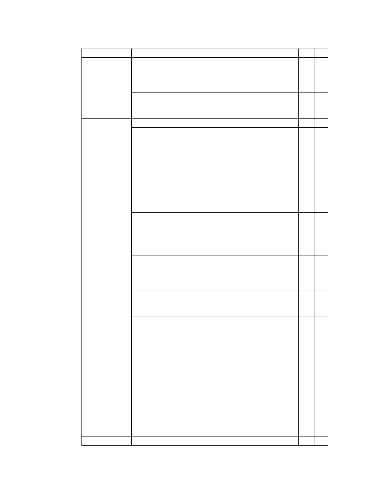
ITEM SPECIFICATIONS 1 2
Power Source: 120 V AC ±10%, 60Hz ±0.5%
o
o
Consumption: Approx. 18 watts (Power on), Approx. 6
watts (Power off)
Approx. 23 watts (Power on), Approx. 7 watts (Power off)
o --
o
Video Head: 4 rotary heads helical scanning system o o
Input Level: VIDEO IN Jack (Phono type) 1.0 Vp-p 75
ΩΩΩΩ
unbalanced
Output Level: VIDEO OUT Jack (Phono type) 1.0 Vp-p 75
ΩΩΩΩ
unbalanced
Signal-to-Noise Ratio: SP: more than 43 dB
LP/SLP: more than 41 dB
Horizontal Resolution: Color/Monochrome: more than 230
lines
o o
Audio Head: Normal Mono: 1 stationary head
Hi-Fi Stereo: 2 rotary heads
o -o
o
Input Level: AUDIO IN Jack (Phono type) -10 dBV 50 k
ΩΩΩΩ
unbalanced
Output Level: AUDIO OUT Jack (Phono type) -8 dBV 600
ΩΩΩΩ
unbalanced
AUDIO OUT Jack (Phono type) -8 dBV 1 k
ΩΩΩΩ
unbalanced
o
o
-
o
o
Frequency Response: Normal Mono: SP: 100 Hz ~ 8 kHz
LP: 100 Hz ~ 6 kHz
SLP: 100 Hz ~ 5 kHz
Hi-Fi Stereo: SP/LP/SLP: 20 Hz ~ 20 kHz
o
o
o
-
o
o
o
o
Signal-to-Noise Ratio: Normal Mono: SP: more than 42 dB
LP/SLP: more than 40 dB
Hi-Fi Stereo: SP/LP/SLP: more than 60 dB
o
o
-
o
o
o
Wow and Flutter: Normal Mono: SP: Less than 0.2%
WRMS
LP: Less than 0.3% WRMS
SLP: Less than 0.4% WRMS
Hi-Fi Stereo: Less than 0.015% WRMS
o
o
o
-
o
o
o
o
RF Out
CH 3/CH 4 switchable 72 dB
µµµµ
(open voltage) 75
ΩΩΩΩ
unbalanced
o o
Tuner Broadcast Channels: VHF 2 ~ 13, UHF 14 ~ 69
CATV Channels: Midband A through I (14 ~ 22)
Superband J through W (23 ~ 36)
Hyperband AA ~ EEE (37 ~ 64)
Lowband A-5 ~ A-1 (95 ~ 99)
Special CATV channel 5A (01)
Ultraband 65 ~ 94, 100 ~ 125
o o
Video Signal EIA Standard (525 lines, 60 fields) NTSC Color Signal o o
2
Tape Speed SP: 1-5/16 i.p.s (33.35 mm/sec), LP: 21/32 i.p.s (16.67
mm/sec),
SLP: =7/16 i.p.s (11.12 mm/sec)
Record/Playback Time: 8 Hrs with 160 min. type tape used
in SLP mode
FF/REW Time: Less than 5 min. (120 min. type tape)
o o
Tape Format Tape width 1/2° (12.7 mm) high density tape o o
Operating
Condition
41=A1F (5=A1C) ~ 104=A1F (40=A1C) (Temperature)
10% ~ 75% (Humidity)
o o
Dimension 14-3/16" (360 mm) (W) X 3-1/2" (89 mm) (H) X 11-1/4" (285
=mm) (D)
o o
Weight Approx. 7.9 lbs. (3.6 kg)
Approx. 8.2 lbs. (3.7 kg)
o --
o
1
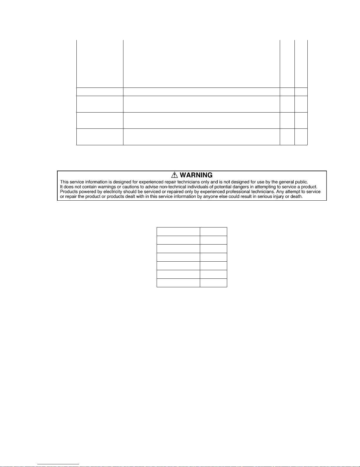
Use The Marks(A,B,...)shown in the chart bellow to distinguish the
different moddels included in this Service Manual.
MODEL MARK
PV-4601 A A
PV-4601 B B
PV-4601 -K C
PV-4651 D
PV-4651-K E
NOT USED Z
3
IMPORTANT SAFETY NOTICE
There are special components used in this equipment which are important for safety.
These parts are marked by /triangle =up triangle, open]in the Schematic Diagrams,
Circuit Board Diagrams, Exploded Views and Replacement Parts List. It is essential
that these critical parts should be replaced with manufacturer's specified parts to
prevent shock, fire or other hazards. Do not modify the original design without
permission of manufacturer.
1. SAFETY PRECAUTIONS
1.1. GENERAL GUIDELINES
1. When servicing, observe the original lead dress. If a short circuit is found, replace
all parts which have been overheated or damaged by the short circuit.
2. After servicing, see to it that all the protective devices such as insulation barriers,
insulation papers shields are properly installed.
3. After servicing, make the following leakage current checks to prevent the customer
from being exposed to shock hazards.
1.2. LEAKAGE CURRENT COLD CHECK
1. Unplug the AC cord and connect a jumper between the two prongs on the plug.
4
2. Measure the resistance value, with an ohmmeter, between the jumpered AC plug
and each exposed metallic cabinet part on the equipment such as screwheads,
connectors, control shafts, etc. When the exposed metallic part has a return path
to the chassis, the reading should be between 1M ohm and 5.2M ohm. When the
exposed metal does not have a return path to the chassis, the reading must be
∞∞∞∞
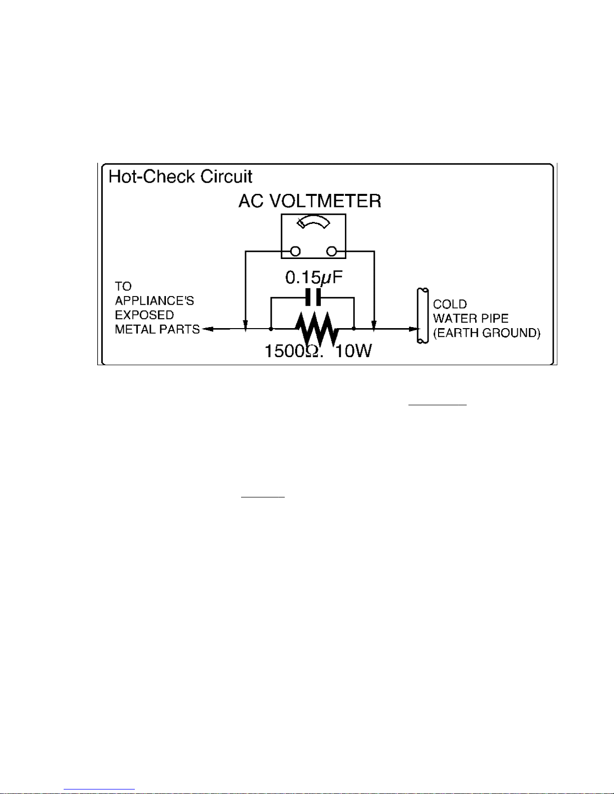
Figure 1
1.3. LEAKAGE CURRENT HOT CHECK (See Figure 1.)
1. Plug the AC cord directly into the AC outlet. Do not use an isolation transformer for
this check.
2. Connect a 1.5K ohm, 10 watts resistor, in parallel with a 0.15 micro farad capacitor,
between each exposed metallic part on the set and a good earth ground such as a
water pipe, as shown in
Figure 1.
3. Use an AC voltmeter, with 1000 ohms/volt or more sensitivity, to measure the
potential across the resistor.
4. Check each exposed metallic part, and measure the voltage at each point.
5. Reverse the AC plug in the AC outlet and repeat each of the above measurements.
6. The potential at any point should not exceed 0.75 volts RMS. A leakage current
tester (Simpson Model 229 or equivalent) may be used to make the hot checks,
leakage current must not exceed 1/2 milliamp. In case a measurement is outside of
the limits specified, there is a possibility of a shock hazard, and the equipment
should be repaired and rechecked before it is returned to the customer.
2. PREVENTION OF ELECTRO STATIC DISCHARGE
(ESD) TO ELECTROSTATICALLY SENSITIVE(ES)
5

DEVICES
Some semiconductor (solid state) devices can be damaged easily by static electricity.
Such components commonly are called Electrostatically Sensitive (ES) Devices.
Examples of typical ES devices are integrated circuits and some field-effect
transistors and semiconductor "chip" components. The following techniques should
be used to help reduce the incidence of component damage caused by electro static
discharge (ESD).
1. Immediately before handling any semiconductor component or
semiconductor-equipped assembly, drain off any ESD on your body by touching a
known earth ground. Alternatively, obtain and wear a commercially available
discharging ESD wrist strap, which should be removed for potential shock
reasons prior to applying power to the unit under test.
2. After removing an electrical assembly equipped with ES devices, place the
assembly on a conductive surface such as aluminum foil, to prevent electrostatic
charge buildup or exposure of the assembly.
3. Use only a grounded-tip soldering iron to solder or unsolder ES devices.
4. Use only an anti-static solder removal device. Some solder removal devices not
classified as "antistatic (ESD protected)" can generate electrical charge sufficient
to damage ES devices.
5. Do not use freon-propelled chemicals. These can generate electrical charges
sufficient to damage ES devices.
6. Do not remove a replacement ES device from its protective package until
immediately before you are ready to install it. (Most replacement ES devices are
packaged with leads electrically shorted together by conductive foam, aluminum
foil or comparable conductive material).
7. Immediately before removing the protective material from the leads of a
replacement ES device, touch the protective material to the chassis or circuit
assembly into which the device will be installed.
CAUTION : Be sure no power is applied to the chassis or circuit, and observe all
other safety precautions.
8. Minimize bodily motions when handling unpackaged replacement ES devices.
(Otherwise harmless motion such as the brushing together of your clothes fabric
or the lifting of your foot from a carpeted floor can generate static electricity (ESD)
sufficient to damage an ES device).
"NOTE to CATV system installer:
This reminder is provided to call the CATV system installer's attention to Article
820-22 of the NEC that provides guidelines for proper grounding and, in particular,
specifies that the cable ground shall be connected to the grounding system of the
building, as close to the point of cable entry as practical."
6
Model : D, E
Equipped with dbx ® -TV Noise Reduction for true MTS reproduction. dbx ® -TV
Noise Reduction is required for good stereo separation and audio fidelity.
3. SUMMARY
3.1. BASIC OPERATIONS
3.2. HELPFUL SERVICE NOTES AND CAUTIONS (Please read)
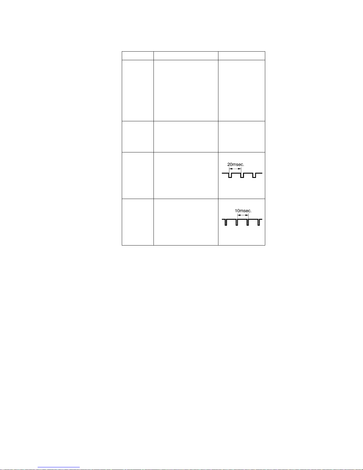
3.2.1. Simplified Fault Finding Data
Simplified Self-Diagnostic System facilitates finding the cause of the fault. A 4 digit
fault code will be displayed in F.I.P.
The Simplified Fault finding data is memorized for approximately 12 hours. This data
is cleared after it is displayed and then the Power button is pressed back on.
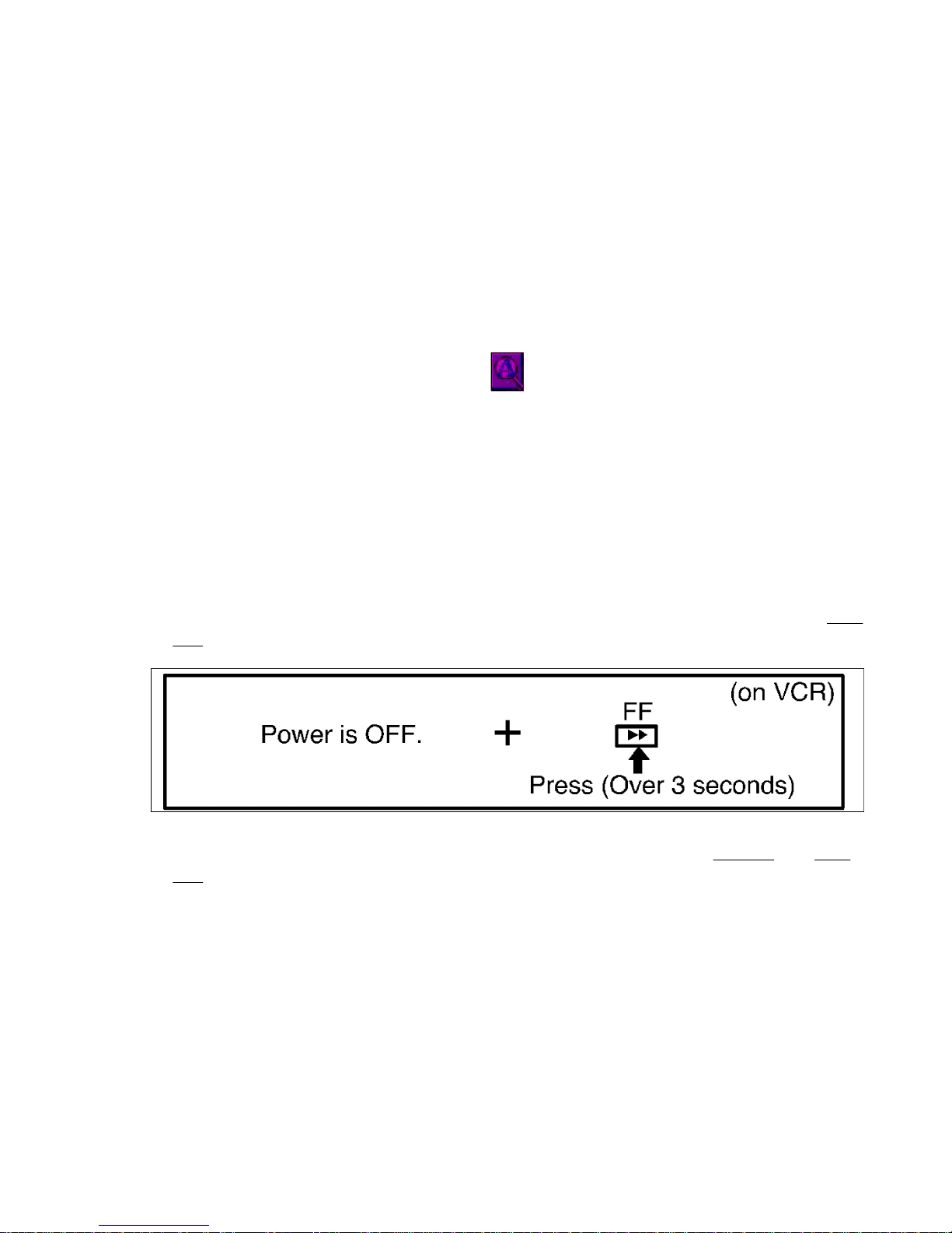
1. With power turned off, press FF button on VCR for over 3 seconds as shown in
Fig.
1-1.
Fig. 1-1
2. Fault code (4 digit number) will be displayed in F.I.P. as shown in Fig. 1-2 and Fig.
1-3.
7
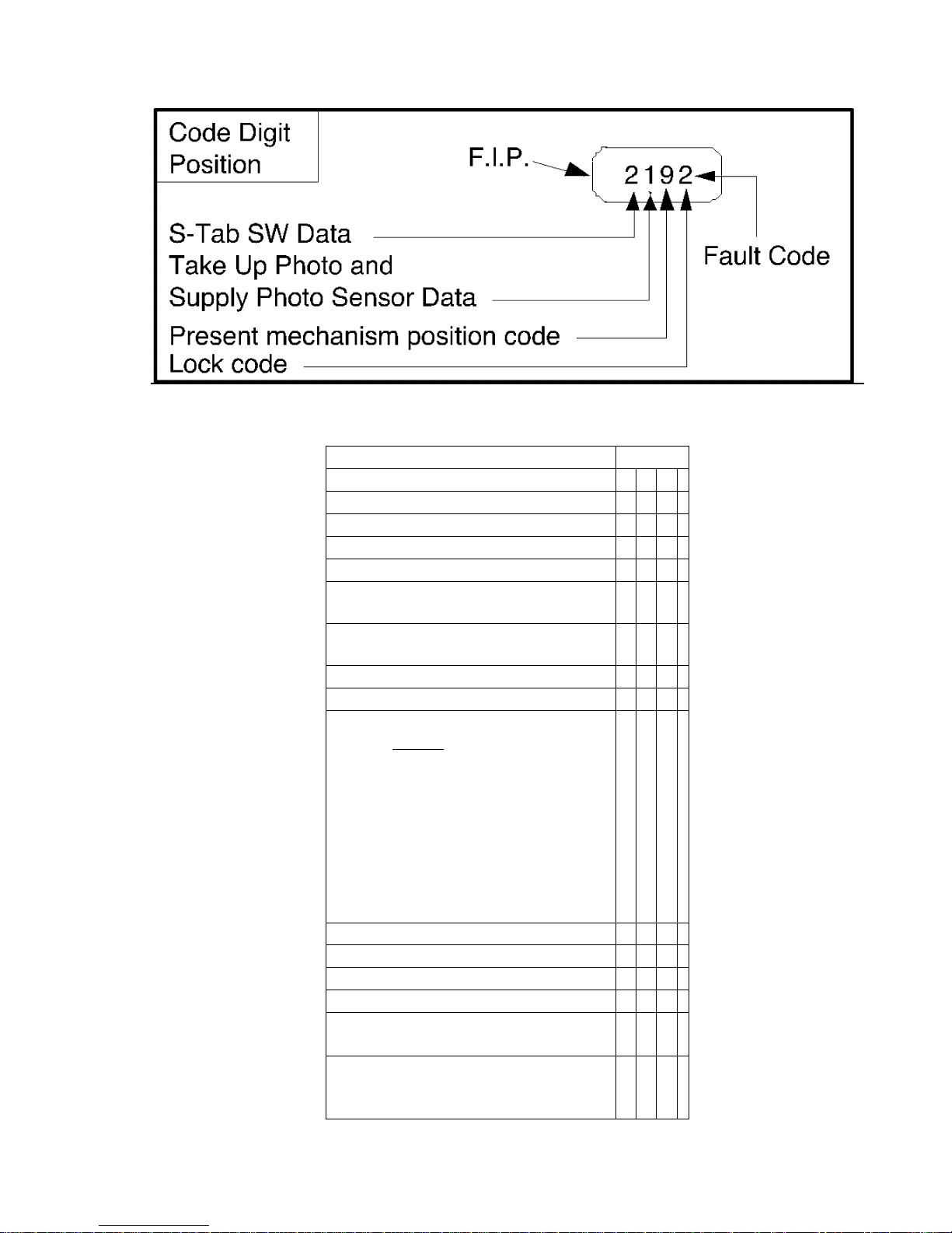
Fig. 1-2
Fig. 1-3
Explanation of Codes Code No.
S-Tab SW Data
- S-Tab SW is off. 1
- S-Tab SW is on. 2
Take Up and Supply Photo Sensor Data
- No light detected at either sensor. 1
- Take Up Photo Sensor detected at
beginning of tape.
2
- Supply Photo Sensor detected at end
of tape.
3
- Light detected at both sensors. 4
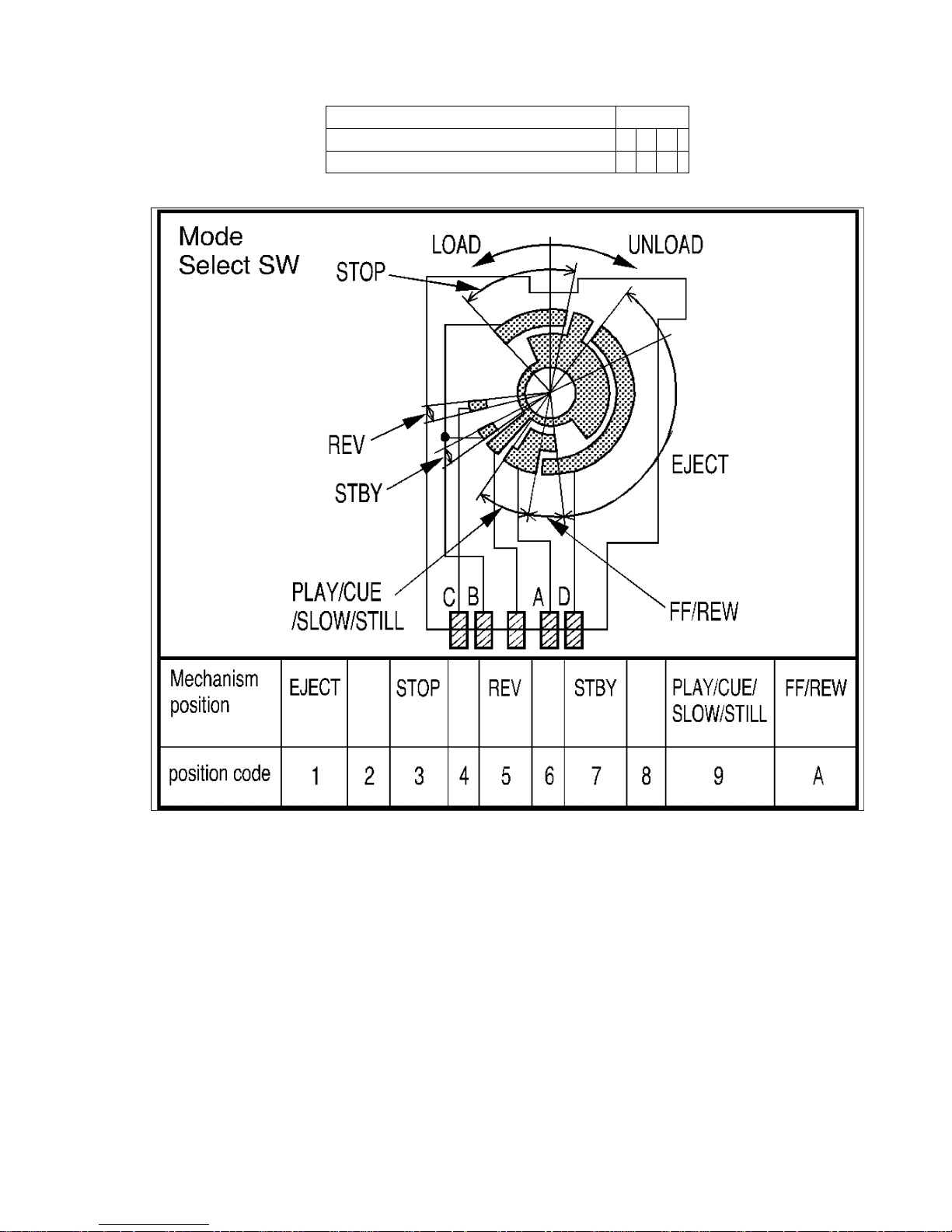
Present Mechanism Position Code
Mechanism Position is indicated.
(Refer to
Fig. 1-4.)
1
2
3
4
5
6
7
8
9
A
Lock Code
- VCR is not in shut-off condition. 0
- Reel lock. 1
- Cylinder lock. 2
- Exceeds loading/unloading time.
(Mechanism Lock)
3
- Exceeds Cassette loading/unloading
time.
(Cassette Lock)
8
Explanation of Codes Code No.
Tape Loading (direction) 1 4
Tape Unloading (direction) 2 4
Fig. 1-4
3. While pressing down FF button on VCR with power turned off, press any operation
button on either VCR, or remote to detect that a key has been pressed.
1st digit changes to "0" only when key is detected.
9
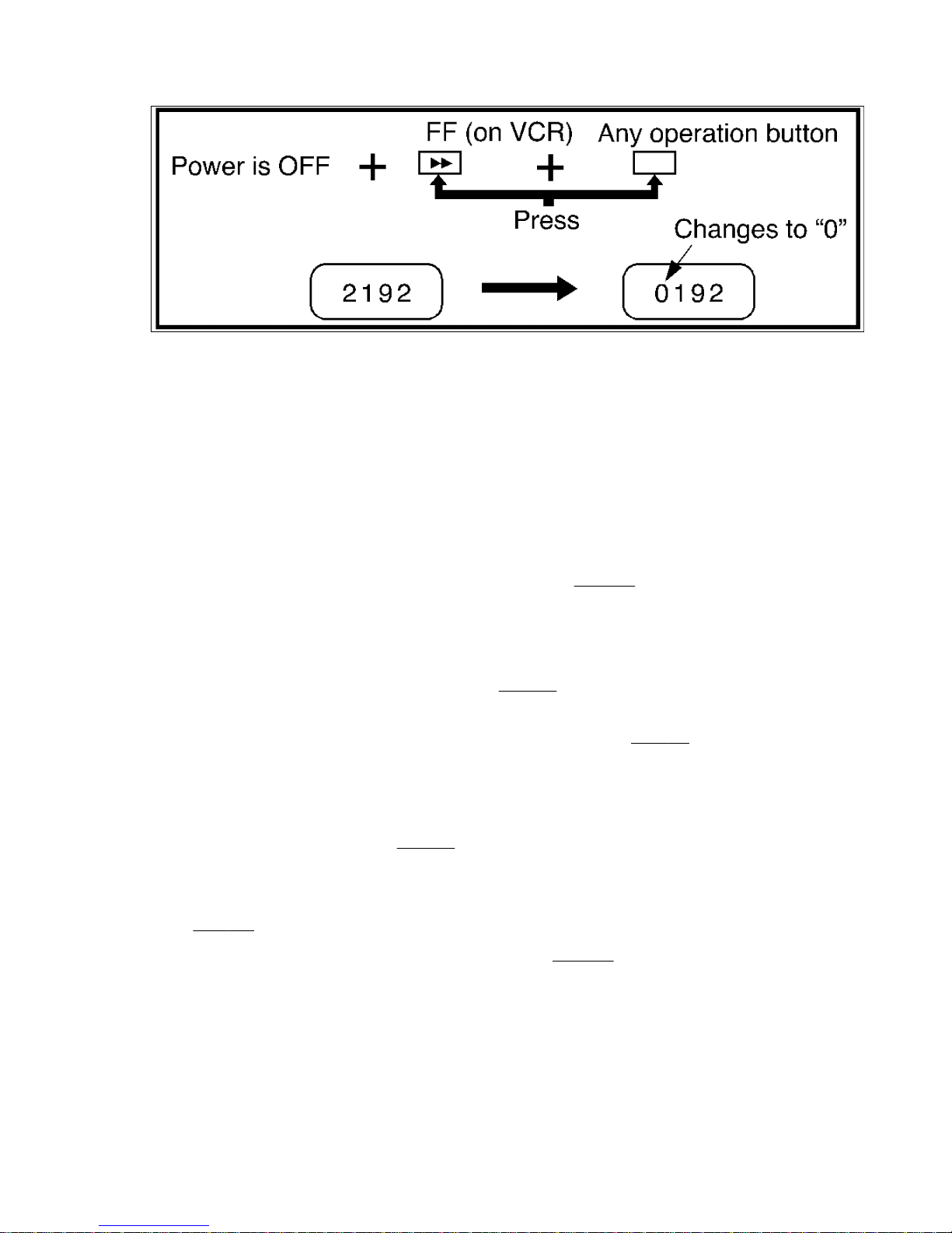
Fig. 1-5
Note:
When 1 to 4 listed in Lock code occurs, the VCR goes into VCR shut-off condition.
VCR stops and all VCR function buttons except for power become non-operational.
3.2.2. Service Position
1. Service Position (1)
Service Position (1) is used for checking and replacing Mechanical and Electrical
parts.
To position the VCR Unit for servicing as shown in
Fig. 2-1, use the following
procedure.
1. In the order described in the Disassembly of Cabinet Parts Section, remove the
Top Cover, Power Supply Ass'y and Front Panel Ass'y .
2. Remove Screw (S-4) and Screw (S-5) in
Fig. D4, Page 2-2.
3. Remove 2 Screws (S-6), 2 Screws (S-7), 2 Screws (S-8), Screw (S-9), Screw (S-10),
Screw (S-11), 2 Screws (S-12), and the Chassis Plate in
Fig. D7, Page 2-3.
4. Remove the VCR Chassis Unit.
Refer to Note Item 5 and "How to remove the VCR Chassis Unit from the frame,"
Page 1-11.
5. Remove 2 Screws (S-13) in
Fig. D8, Page 2-3.
6. Open the Mechanism Chassis and Cassette Up Ass'y.
7. Place the left side of the Cassette Up Ass'y on the front side of the Frame as shown
in
Fig. 2-1.
8. Reinstall the Power Supply Ass'y as shown in
Fig. 2-1, refer to Note Item 4.
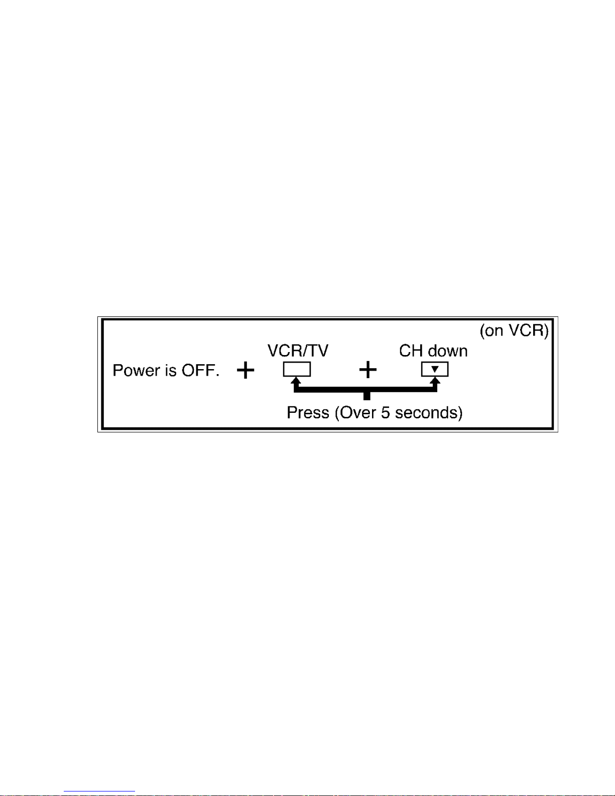
9. Press VCR/TV button and CH down button together on VCR for over 5 seconds in
power off condition or Place a jumper between TP6001 and GND.
10
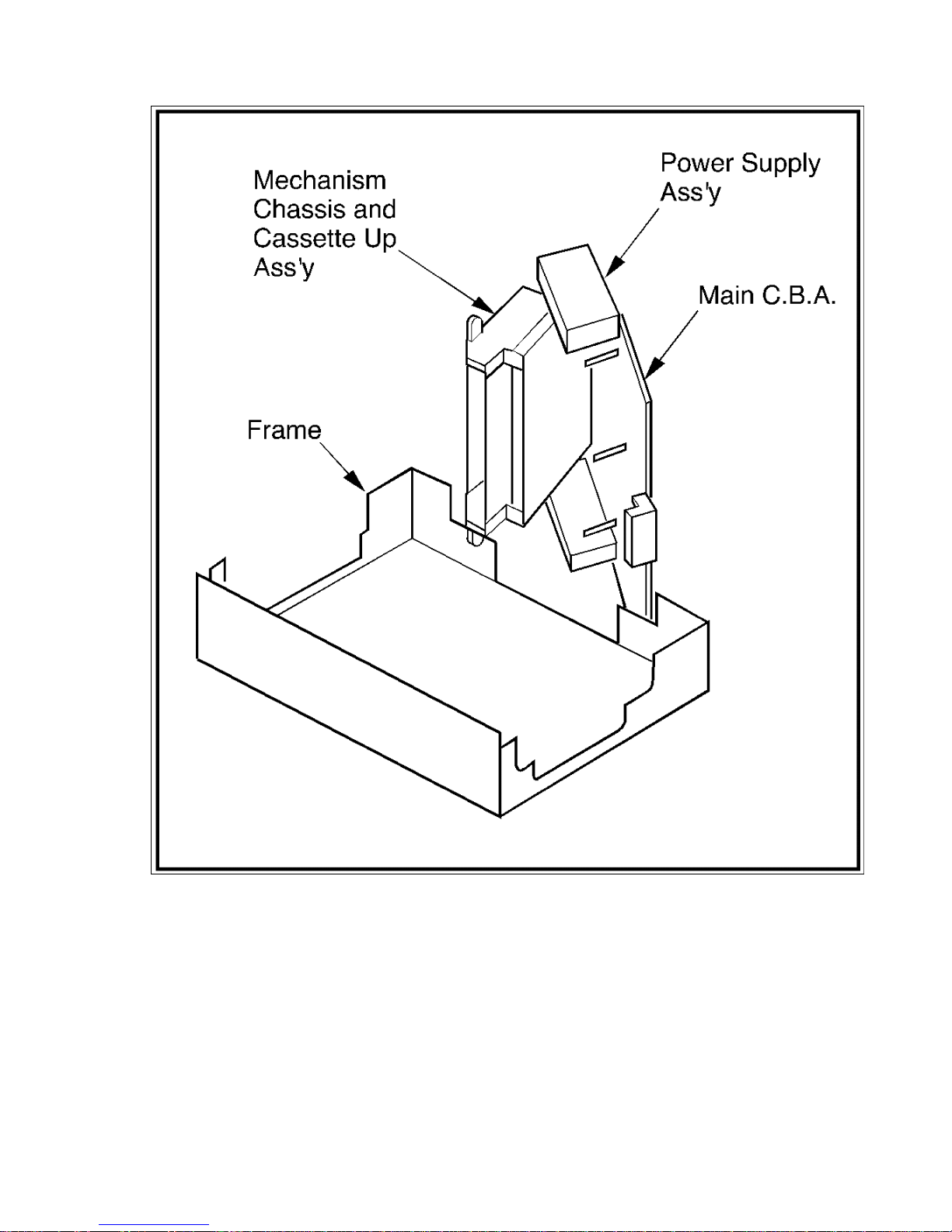
Fig. 2-1
Note:
1. When placing the unit into the Service Position (1), Beats may be seen in the
picture. However, when the Red Screw between the Main C.B.A. and the Power
Supply AssÕy is tightened, the Beats in the picture will be eliminated. So, place a
short ground jumper wire between the Power Supply AssÕy and the Main C.B.A.
while operating in the Service Position (1).
2. When servicing in Service Position (1), do not use a T160 tape. It may cause a Tape
Jam.
3. If misloading of the cassette tape is encountered in this position, press the
11
Cassette Tape firmly into the Cassette Up Ass'y with your left thumb.
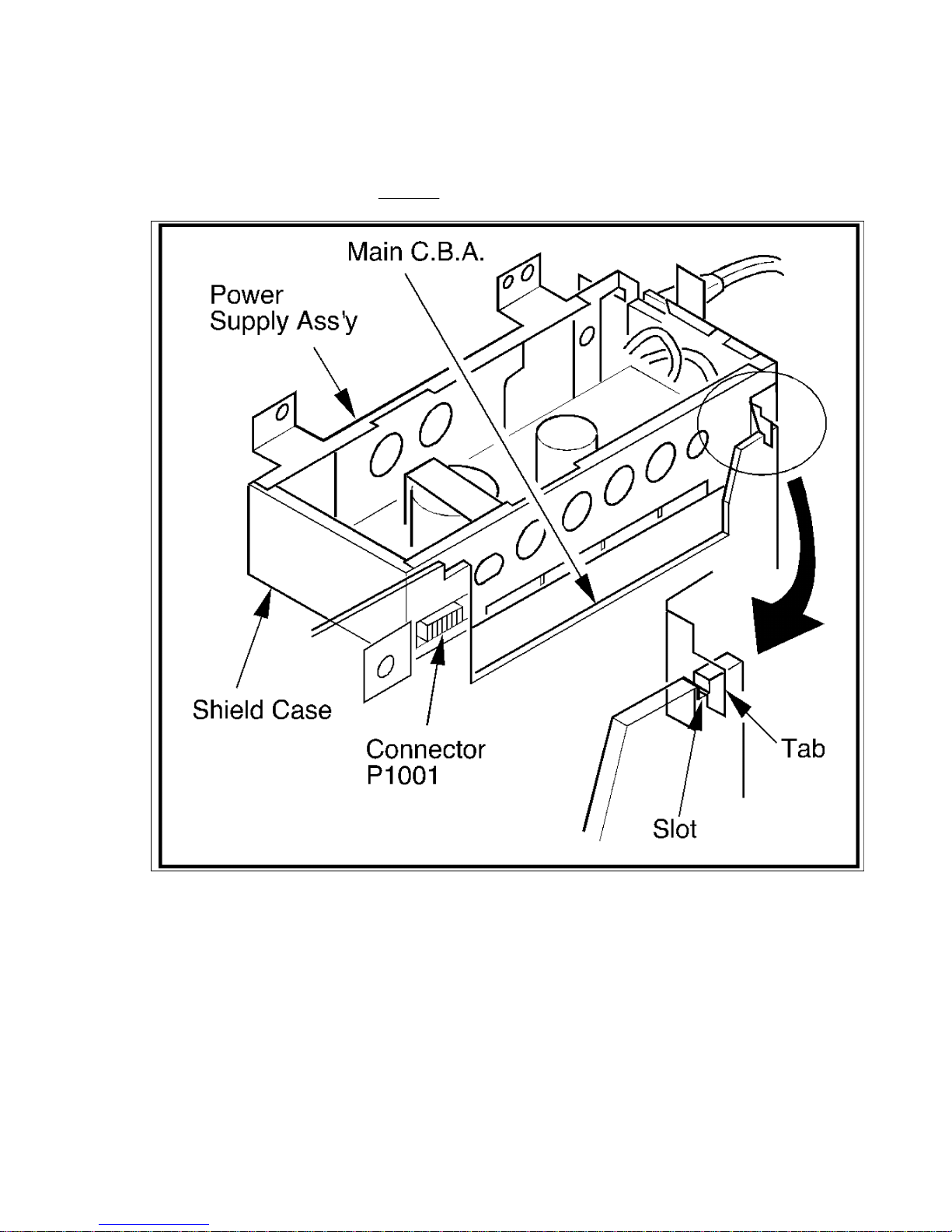
4. To install the Power Supply Ass'y to the Main C.B.A.:
Connect connector P1001 and hook the tab of the Shield Case to the slot of the
Main C.B.A. as shown in
Fig. 2-2.
Fig. 2-2
5. When lifting up the VCR Chassis Unit, do not pull up on the Top Plate of the
Cassette Up Ass'y.
6. Model : D, E
When raising or opening the mechanism, place something insulated between the
Hi-Fi Audio/Video Head Amp Ass'y and Audio Jack.
Service Position (2)
Service position (2) is used to check the Mechanism and Electronic Circuits.
12

In this position, check the movement of mechanical parts on the Mechanism Chassis
and replace parts as needed.
In this position, checking is limited on the electronic circuit of the Main C.B.A. from
the component side.
To position the VCR Unit for servicing as shown in
Fig. 2-3, use the following
procedure.
1. In the order described in the Disassembly of Cabinet Parts Section, remove the
Top Cover and Front Panel Ass'y.
2. Remove Screw (S-5) in
Fig. D4, Page 2-2.
3. Remove 2 Screws (S-6), 2 Screws (S-7), 2 Screws (S-8), Screw (S-9), Screw (S-10),
Screw (S-11) and the Chassis Plate in
Fig. D7, Page 2-3.
4. Remove 2 Screws (S-13) in
Fig. D8, Page 2-3.
5. Raise the Mechanism Chassis and secure it using the Chassis Plate which was
used to secure the Mechanism Chassis on the frame as shown in
Fig. 2-3.
6. Press VCR/TV button and CH down button together on VCR for over 5 seconds in
power off condition or Place a jumper between TP6001 and GND.
13
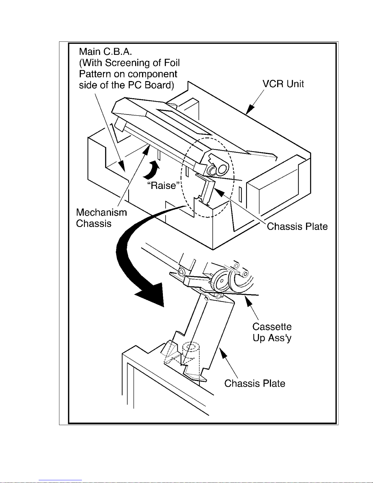
Fig. 2-3
14
3.2.3. How to reset all VCR Memory functions
To reset (clear) the select language, channel auto set and set clock functions to their
initial power on condition (power on, no cassette inserted), hold down the PLAY and
REWIND buttons together on VCR for more than 5 seconds. Power will shut off .
3.2.4. Service Mode
In order to inhibit detection of the Supply and Takeup Photo Transistors, Reel
Sensor, and Cylinder Lock, press VCR/TV button and CH down button together on
VCR for over 5 seconds in power off condition.
The power comes on and the unit goes into service mode.
Mechanism movement can be confirmed without a cassette in this mode.
To release from this mode, press POWER button off or disconnect AC Plug.
(Alternative method) Ground the TP6001.
Fig. 3
3.2.5. Test Point Information
15
Test Point purpose operation
TP6001 T o confirm mechanism
movement without a
cassette, the detection
of the Supply / Takeup
Photo Transistors,
Reel Sensor, and
Cylinder Lock will be
inhibited.
Ground the
TP6001
TP6003 T o defeat the Auto
Tracking Function.
(Maintain the Neutral
Position.)
Place a jumper
between TP6003
and
TP6009(+5V).
TP6011 A check Terminal for
judgment of the IC6001
microprocessor.
The microprocessor is
OK if there is Scan
pulse output.
TP6301 A check Terminal for
judgment of the IC6301
microprocessor.
The microprocessor is
OK if there is pulse
output.
3.2.6. Easy check of Power Supply Ass'y, Hi-Fi Audio C.B.A., UHF/VHF
Tuner/TV Demodulator Unit
Power Supply Ass'y, Hi-Fi Audio C.B.A., UHF/VHF Tuner/TV Demodulator Unit can be
checked easily through holes in the bottom of the frame after removing the Bottom
Panel. You can check connector pins of following units and C.B.A.s.
-
P1051 (Pins of Power Supply Ass'y)
-
Pins of UHF/VHF Tuner/TV Demodulator Unit.
-
Model : D, E
P4201,P4202,P4203 (Pins of Hi-Fi Audio C.B.A.)
16
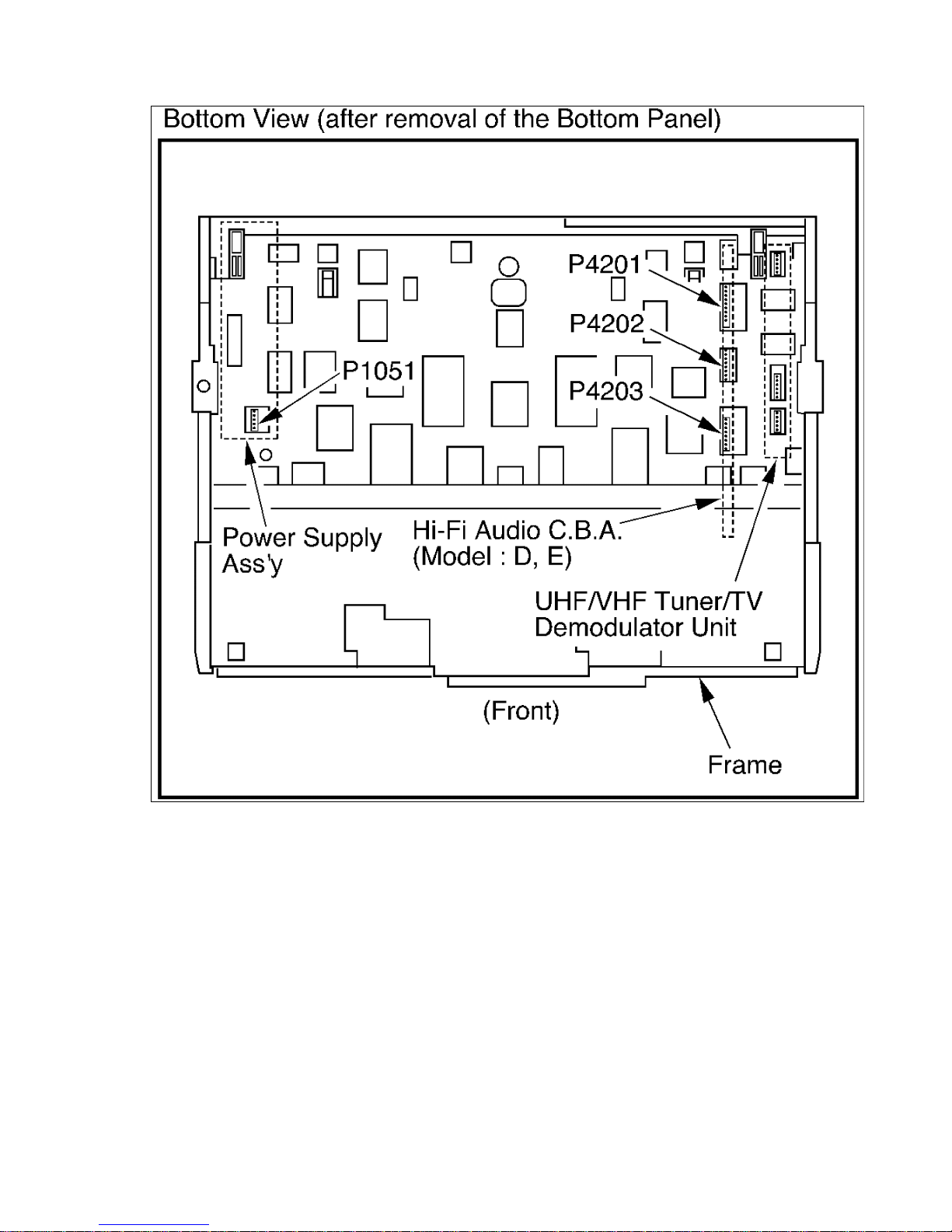
Fig. 4
3.2.7. VCR Lock Feature
This feature prohibits all operations except for timer recording, and tape eject. This is
useful to prevent misoperation and protect your VCR.
To set the VCR Lock Feature:
Press STOP/EJECT button on VCR for 7 seconds during Stop, or Power OFF mode.
17
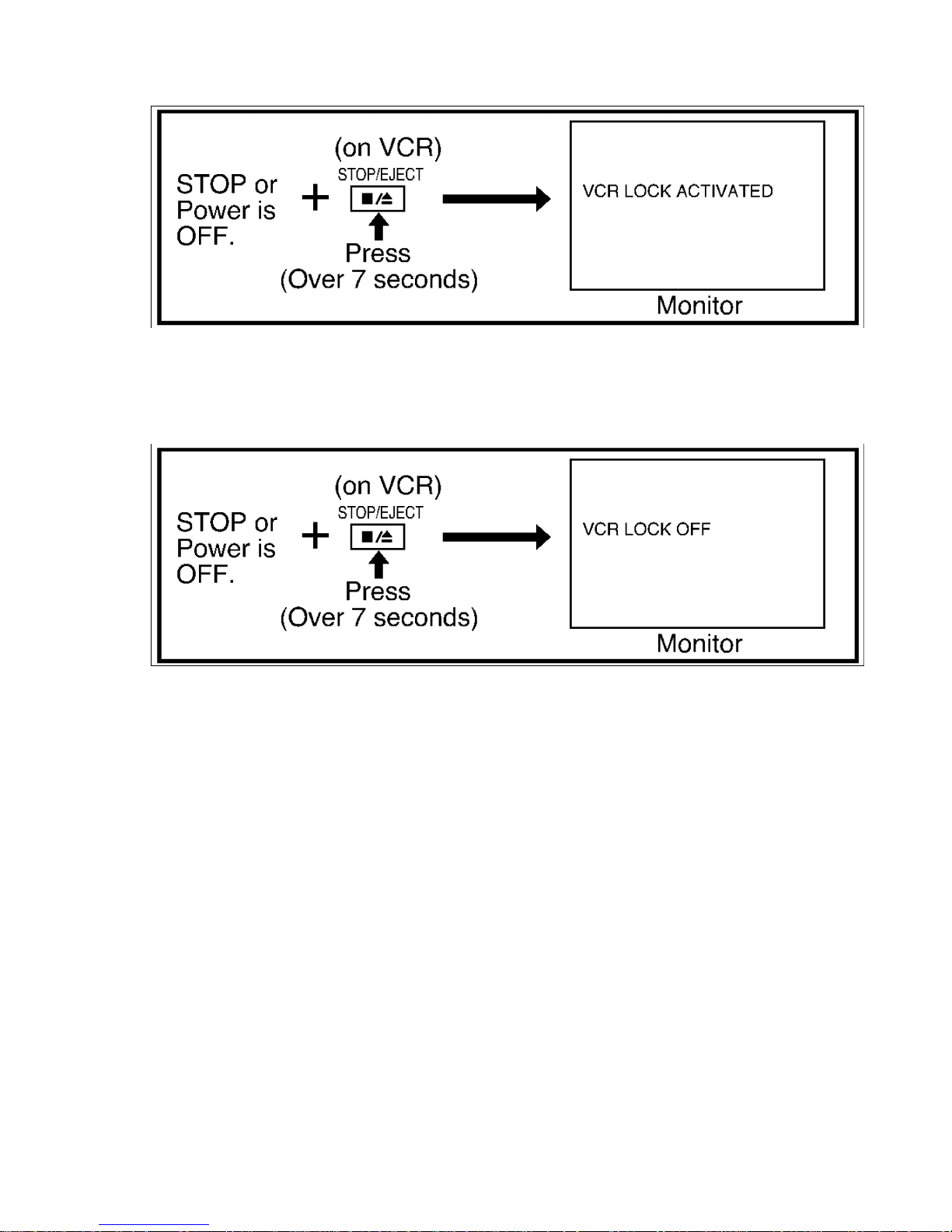
Fig. 5-1
To cancel the VCR Lock Feature:
Press STOP/EJECT button on VCR for 7 seconds again during Stop, or Power OFF
mode.
Fig. 5-2
VCR Lock mode is cancelled automatically after 24 hours when the clock is set.
3.2.8. Set Tracking to the Neutral Position
Pressing eject and reinserting a Tape will initiate the Auto Tracking function from the
Neutral position.
3.2.9. Easy Signal Check Points
Points with marks "V1..., AV1..., CT1... etc." on Main C.B.A. can be used for checking
Video and Audio Signal.
-
V1 to V11 : to check Video Signal
-
AV1 to AV4 : to check Audio Signal
-
CT1 to CT7 : to check Control Signal
Also, power lines are marked with voltage indications (5V, 12V, 14V, 37V, -30V) on
Main C.B.A. for easy checking.
Schematic, C.B.A. and Block Diagrams also show these check points.
18
3.2.10. Function of important Test Points
Function of important Test Points
TP3001 Video signal to Jack
TP3002 PB/REC video envelope signal
TP3009 Video signal from Jack
TP4001 Audio signal from Jack
TP4002 Audio signal to Jack
TP6001 Service Test Point (inhibit sensors)
TP6003 defeat Auto tracking function
(connect to +5V(TP6009))
TP6009 +5V
*TP6010 AIP CTL signal
*TP6011 IC6001 judgment
TP6204 Cylinder PG/FG
TP6205 Head SW
TP6207 PB control pulse
TP6301 IC6301 judgment
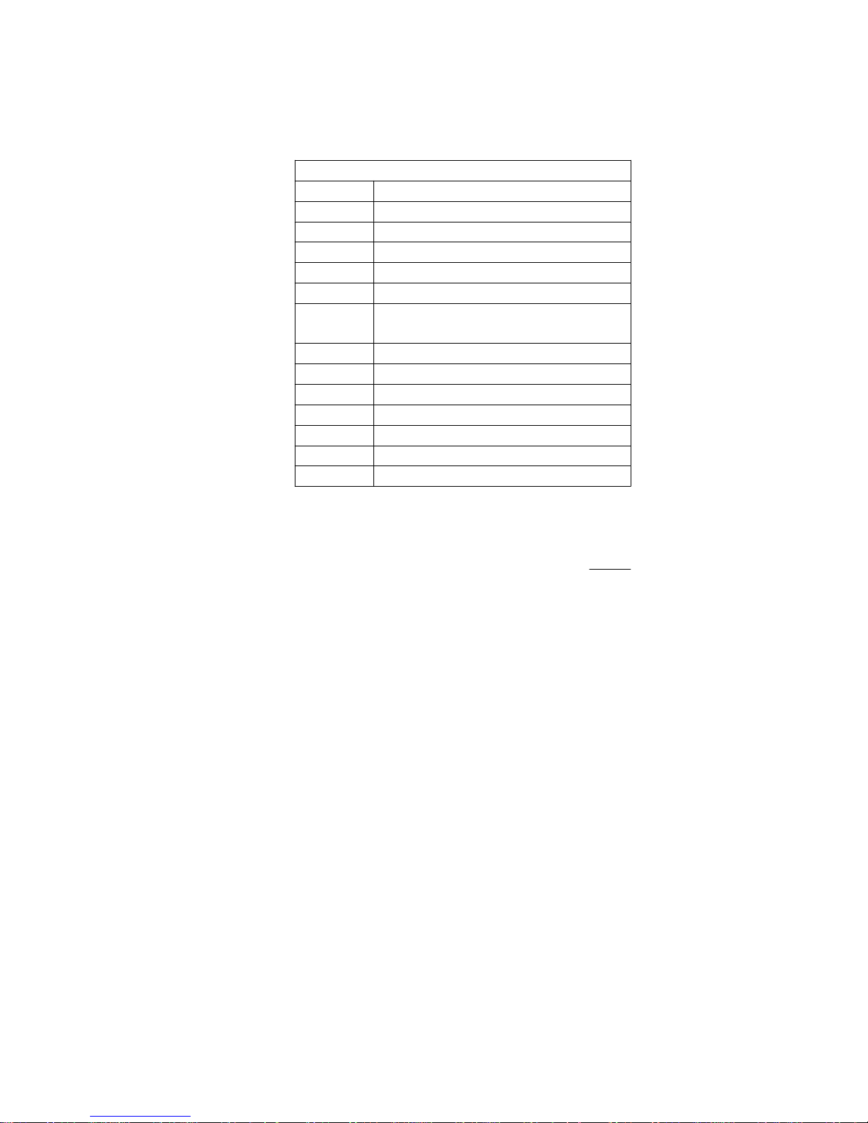
3.2.11. Method for Manual Loading / Unloading of VCR
Turn the Loading Pulley of the Motor Block Ass'y (shown in Fig. 6) counterclockwise
(for loading) or clockwise (for unloading) as viewed from the Front Side.
Note:
DO NOT apply any voltage to the Terminals of the Loading Motor Unit on the Motor
Block Ass'y.
19
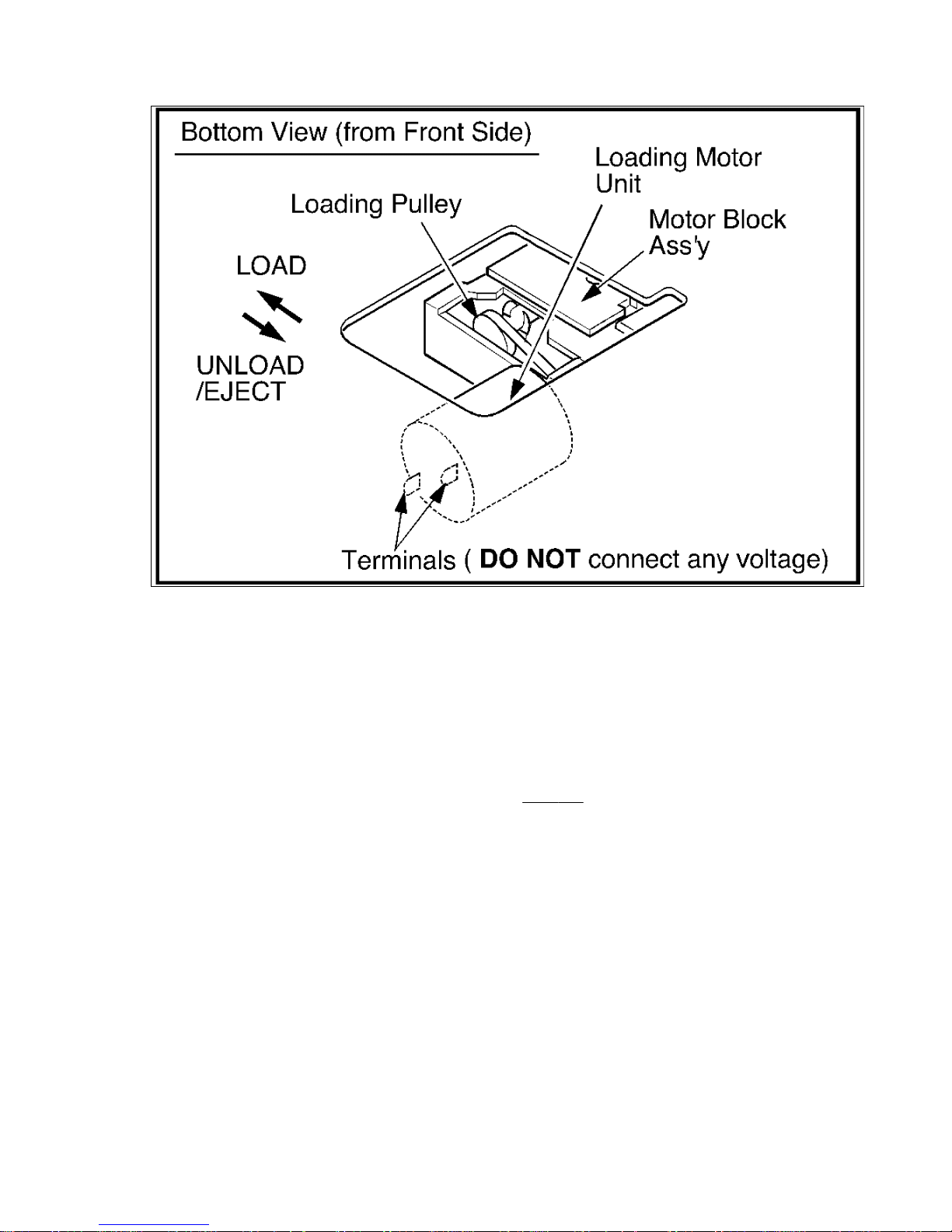
Fig. 6
3.2.12. How to Remove a jammed Tape
A. Electrical Method
1. In the order described in the Disassembly of Cabinet Parts Section, remove the
Top Cover and Front Panel Ass'y.
2. Cut the wire to open Jumper(J6004) on the System Control Section of the Main
C.B.A. from the component side. (Refer to
Fig. 7-1.)
Note:
It is unnecessary to cut both wires (J6004 and J6005).
20
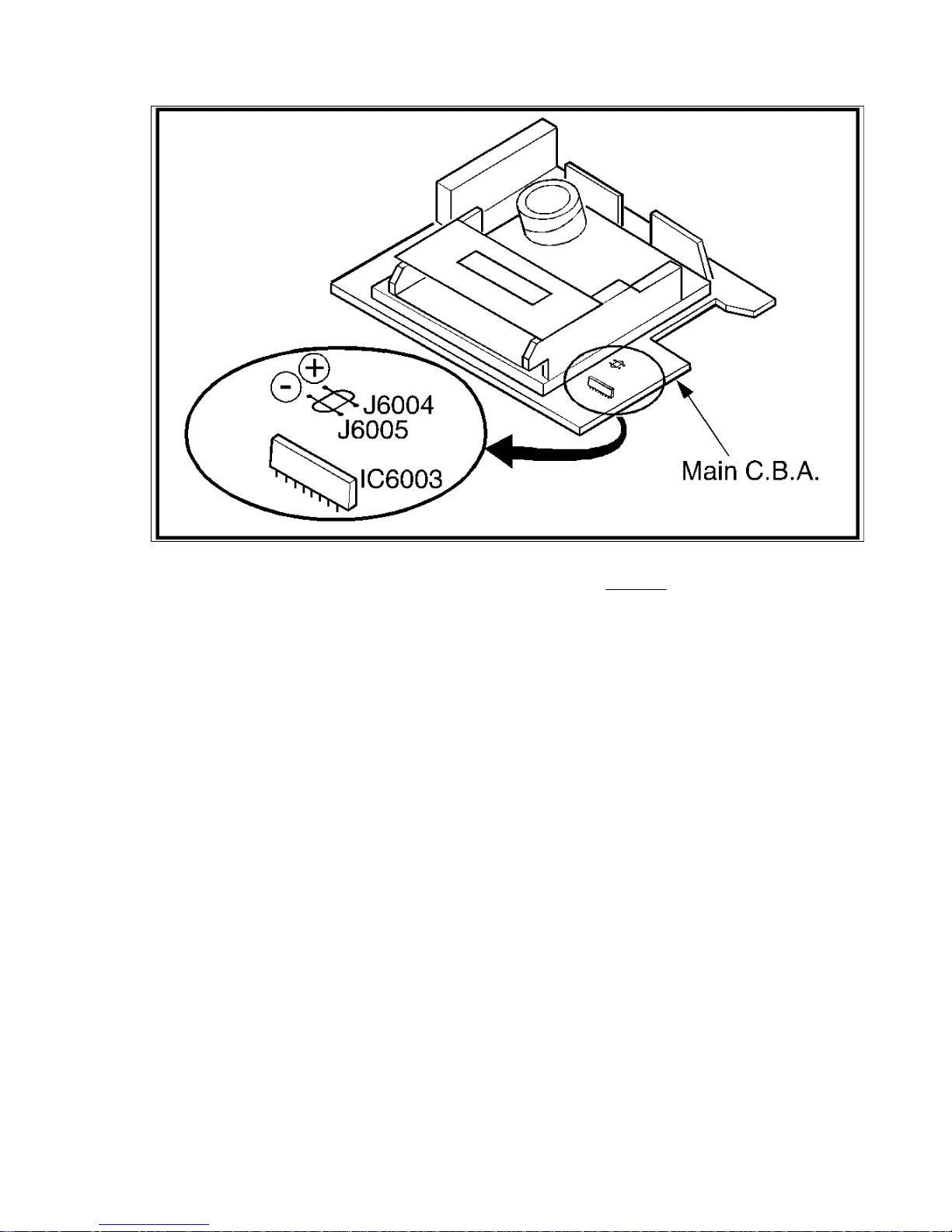
Fig. 7-1
3. Connect a DC Power Supply to the wire as shown in Fig. 7-2, then apply
+6.0+-0.1VDC to J6004 in order to start the unloading operation sequence.
4. When the tape Loading Arms are returned to the fully unloaded position,
disconnect the DC Power Supply Unit to stop the unloading operation.
Note:
Be careful not to let the DC power supply Unit GND contact chassis GND. This
may damage the Loading Motor Drive IC (IC 6003).
Be sure to connect DC +to side (a) of J6004.
If DC + is applied to side (b) of J6004, the Loading Motor Drive IC (IC6003) may be
damaged.
21
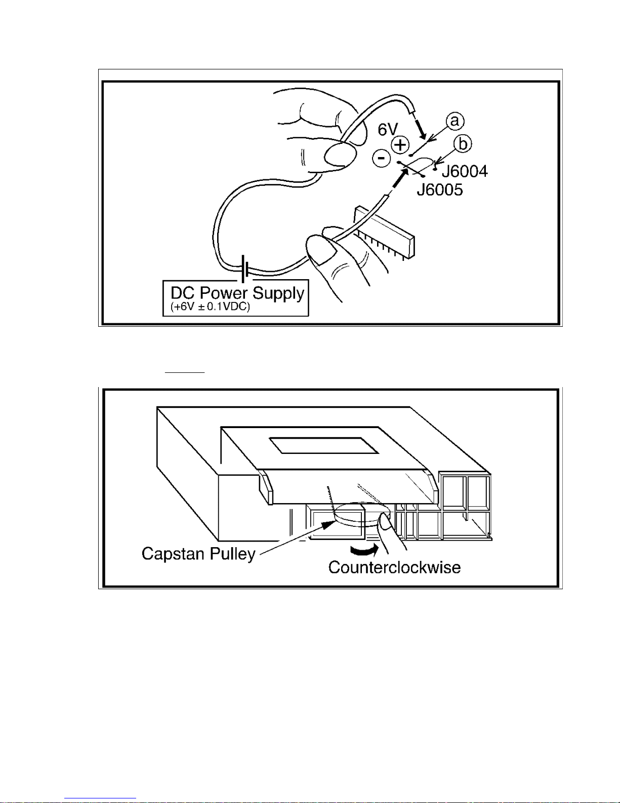
Fig. 7-2
5. To rewind the tape into the cassette, turn the Capstan Pulley counterclockwise as
shown in
Fig. 7-3.
Fig. 7-3
6. Then eject the Tape using the DC Power Supply again.
7. After completion of the procedure, resolder the jumper wire (J6004) that was
opened.
B. Manual Method
1. In the order described in the Disassembly of Cabinet Parts Section, remove the
22

Top Cover and Front Panel Ass'y.
2. Remove a Cut Washer (C-1) on the Pressure Roller Arm Unit as in
Fig. J3, Page
2-16.
3. Remove the Spring of the Pressure Roller Arm Unit as in
Fig. J3.
4. Turn the Pressure Roller Arm counterclockwise and lift it up to release from the
Pressure Roller bracket and shaft.
5. Remove the tape from the tape path and posts.
6. Rewind the tape into the cassette by turning the Capstan Pulley counterclockwise
as in
Fig. 7-3.
7. Remove the Cassette Up Ass'y by removing 2 Screws (S-7), 2 Screws (S-8), 2
Screws (S-14) and 2 Screws (S-15) as in
Fig. D7 and Fig. D9, Page 2-3.
8. Remove the cassette from the Cassette Up Ass'y.
9. Adjust the Mechanical Position into the Eject position by rotating the Loading
Pulley.
10. Remove the Pressure Roller Bracket from shaft and reinstall the Pressure Roller
Arm and spring to the bracket as in
Fig. J3.
11. Reinstall the Pressure Roller Arm Unit and Cut Washer in original position as in
Fig. J3.
12. Reinstall the Cassette Up Ass'y into the Mechanism Chassis.
3.3. OTHER SERVICE NOTES AND CAUTIONS
3.3.1. OTHER SERVICE NOTES AND CAUTIONS
Align the Sensor LED with the hole in the Mechanism Chassis by gently pushing the
Sensor LED backward with your hand. Refer to
Fig. 8.
23
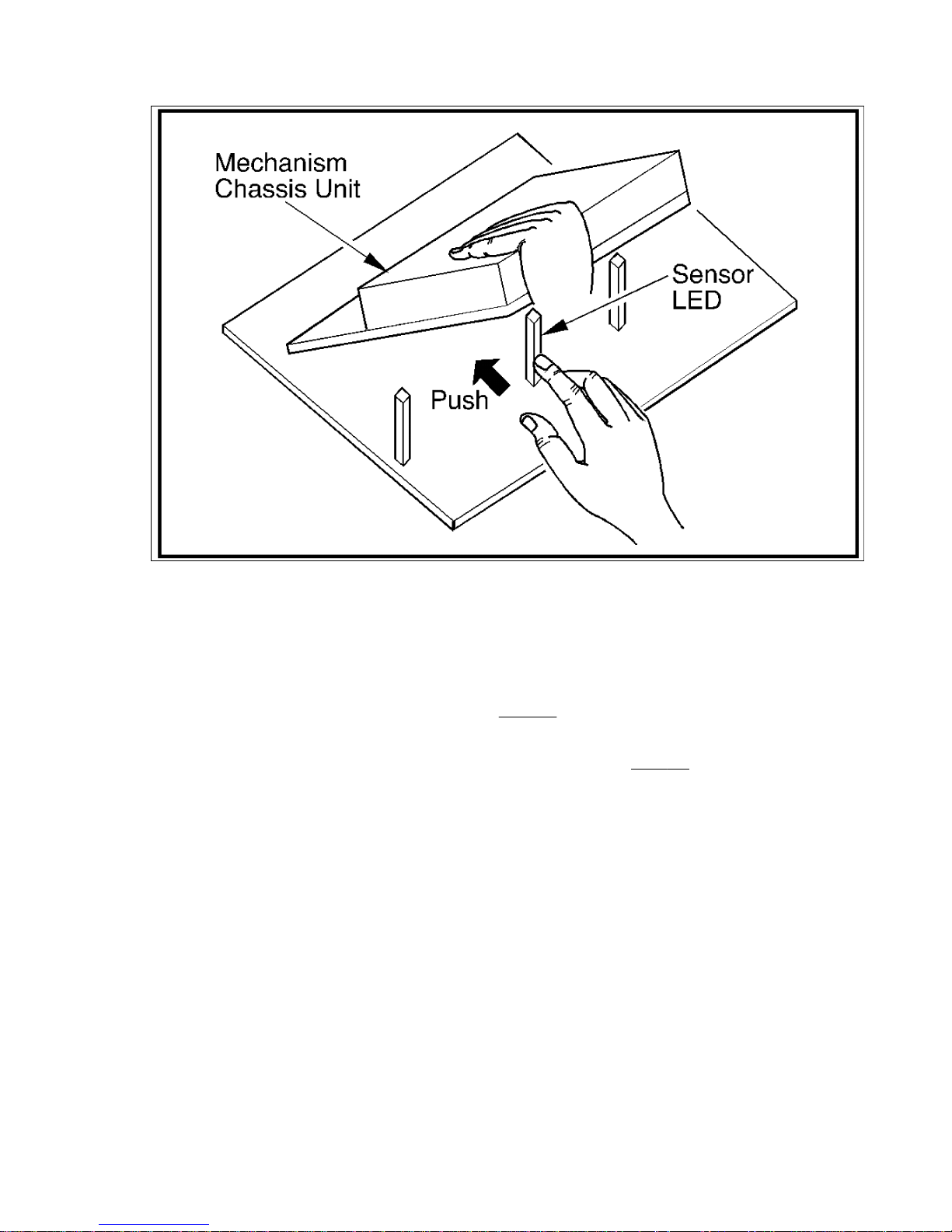
Fig. 8
3.3.2. How to remove the VCR Chassis Unit from the frame:
1. In the order described in the Disassembly of Cabinet Parts Section, remove the
Top Cover, Power Supply Ass'y and Front Panel Ass'y.
2. Remove Screw (S-4) and Screw (S-5) in
Fig. D4, Page 2-2.
3. Remove 2 Screws (S-6), 2 Screws (S-7), 2 Screws (S-8), Screw (S-9), Screw (S-10),
Screw (S-11), 2 Screws (S-12), and the Chassis Plate in
Fig. D7, Page 2-3.
4. While gently lifting the Side Plate L (C) of Cassette Up Ass'y, bent locking tab (A)
and (B) then outward until clear.
5. Lift the Side Plate R (D) until even with the Side Plate L. Then lift entire VCR
Chassis Unit out from the frame.
24
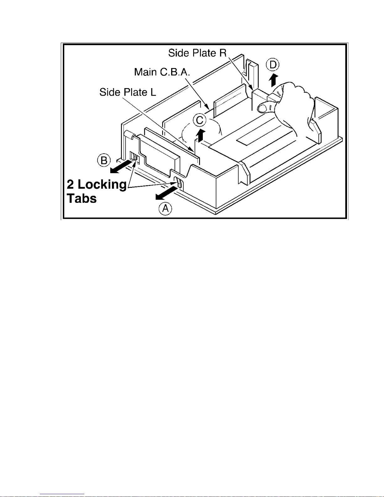
Fig. 9
3.3.3. Handling of the Main C.B.A. when Servicing
DO NOT pull the Main C.B.A. in the direction indicated by the arrow. DO NOT pull
upward while holding the UHF/VHF Tuner/TV Demodulator Unit because you may
crack the Main C.B.A.
25
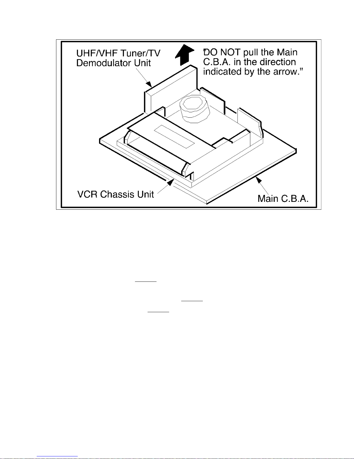
Fig. 10
3.3.4. Removal/Installation of Mechanism Chassis to the Main C.B.A.
Preparation
1. In the order described in the Disassembly of Cabinet Parts Section, remove the
Top Cover and Front Panel Ass'y .
2. Remove Screw (S-5) in
Fig. D4, Page 2-2.
3. Remove 2 Screws (S-6), 2 Screws (S-7), 2 Screws (S-8), Screw (S-9), Screw (S-10),
Screw (S-11) and the Chassis Plate in
Fig. D7, Page 2-3.
4. Remove 2 Screws (S-13) in
Fig. D8, Page 2-3.
a. Removal
Remove the Mechanism Chassis as follows.
1. Lift up the Side Plate -R while holding the Main C.B.A. to disconnect the right rear
mechanism connector.
2. Lift up the Side Plate -L while holding the Main C.B.A. to disconnect the left rear
mechanism connector.
26
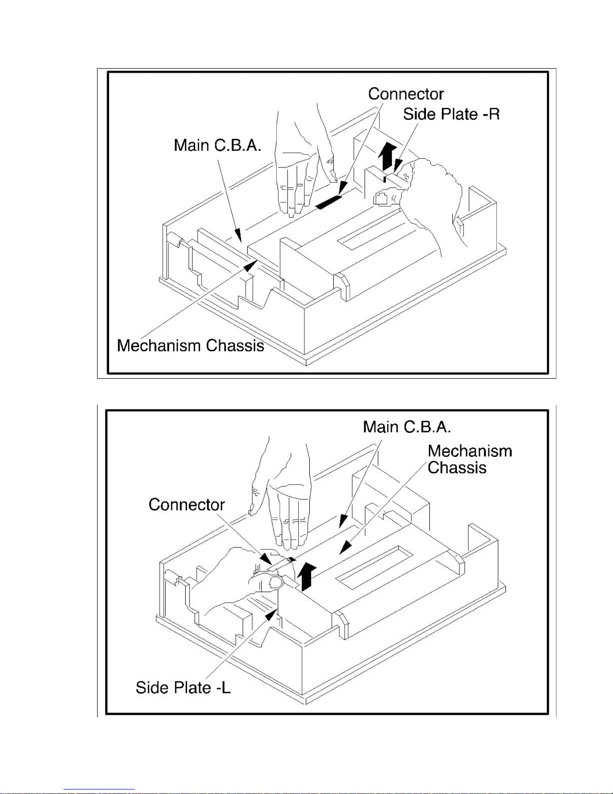
Fig. 11-1-1
27
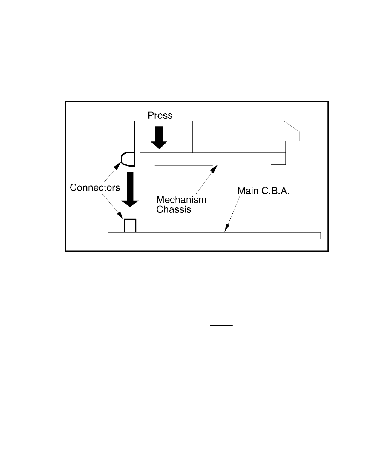
Fig. 11-1-2
b. Installation
Connect the Mechanism Chassis to the Main C.B.A., as shown below. Be sure to
press the rear portion of the mechanism chassis to insert connectors securely.
Fig. 11-2
3.3.5. How to remove the Cassette Up Ass'y
1. In the order described in the Disassembly of Cabinet Parts Section, remove the
Top Cover and Front Panel Ass'y.
2. Remove 2 Screws (S-7) and 2 Screws (S-8) in
Fig. D7, Page 2-3.
3. Remove 2 Screws (S-14), 2 Screws (S-15), in
Fig. D9, Page 2-3.
3.3.6. When installing the Cassette Up Ass'y
When installing the Cassette Up Ass'y onto the Mechanism Chassis, make sure that
the Cassette Up Ass'y and the mechanism are in the Eject position.
See "HOW TO INSTALL CASSETTE UP ASS'Y ONTO MECHANISM CHASSIS," Page
2-23.
3.3.7. Connection of the Flat Cable to Trap Connector
28
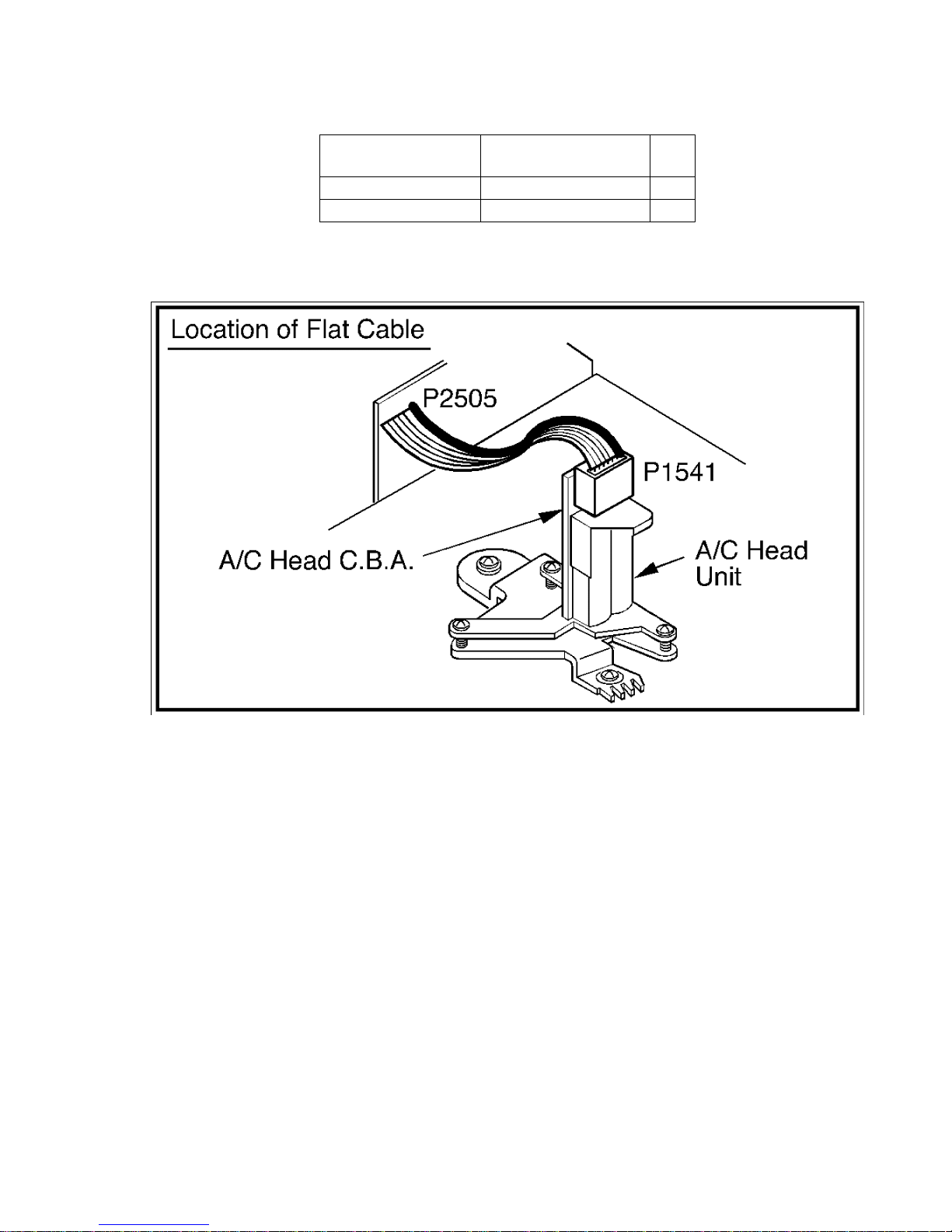
Plug No. Location of Trap
Connectors
Type
P2505-P1541Unit A/C Head A
P3504-FE Head Unit FE Head Unit B
To identify Pin 1 of the Flat Cable, a different Color Identification Line is used.
To locate Pin 1 on the Trap Connector, find the pin 1 indicator on the C.B.A.
Fig. 12-1
29
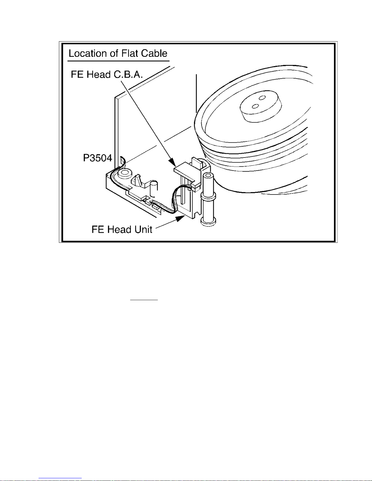
Fig. 12-2
(Removal and Installation of the Flat Cable)
Type A
(Removal)
Pull out the Flat Cable. Minimize stress by holding it securely to avoid damage of the
individual wires. (See
Fig. 12-3.)
(Installation)
Adjust the position of the Flat Cable so that the Identification
Line on the Flat Cable aligns with Pin 1 of the Trap Connector and align the individual
wire with its individual Trap Connector Hole. Then insert the Flat Cable wire into the
Trap Connector.
30
 Loading...