

Page 1
Manufactured by:
81-IN3042-9922
for
Before attempting to connect or operate this product,
please read these instructions completely.
INDOOR CAMERA HOUSING BRACKETS AND MOUNTS
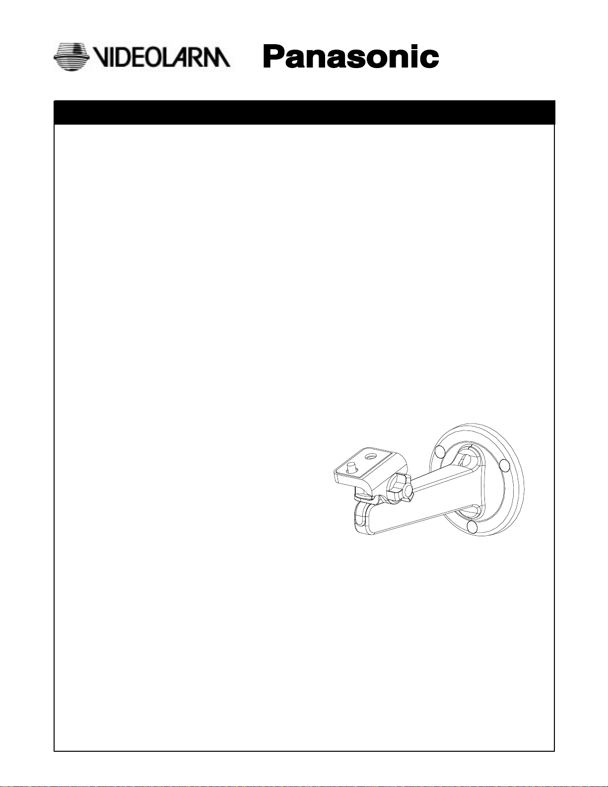
Indoor Plastic Camera Mount
Model Includes: PUM8
DESCRIPTION:
A 6" injection molded off-white Lexan® plastic bracket for indoor use. The bracket is designed to support a CCTV camera with
maximum camera length of 8" for wall mount or ceiling mount environments. The camera mount has full pan/tilt capabilities and
can be adapted quickly and easily for a wall or ceiling mount application.
FEATURES:
• Attractive styling
• Wall or ceiling mount with quick and easy set-up
• Convenient cable access slot
• Pan/tilt adjusts with grip-tight knobs
• Hole covers for concealing mounting hardware
Installation and
Operating Instructions
Page 2
1. Read Instructions - All the safety and operating instructions
!
should be read before the unit is operated.
2. Retain Instructions - The safety and operating instructions
should be retained for future reference.
3. Heed Warnings - All warnings on the unit and in the operating
instructions should be adhered to.
4. Follow Instructions - All operating and user instructions should
be followed.
5. Electrical Connections - Only a qualified electrician should
make electrical connections.
6. Attachments - Do not use attachments not recommended by the
product manufacturer as they may cause hazards.
7. Cable Runs - All cable runs must be within permissible distance.
8. Mounting - This unit must be properly and securely mounted to
a supporting structure capable of sustaining the weight of the
unit. Accordingly:
a. The installation should be made by a qualified service
person and should conform to all local codes.
b. Care should be exercised to select suitable hardware to
install the unit, taking into account both the composition
of the mounting surface and the weight of the unit. Be
sure to periodically examine the unit and the supporting
structure to make sure that the integrity of the
installation is intact. Failure to comply with the foregoing
could result in the unit separating from the support
structure and falling, with resultant damages or injury to
anyone or anything struck by the falling unit.
SAFETY PRECAUTIONSIMPORTANT SAFEGUARDS
CAUTION
RISK OF
ELECTRIC SHOCK!
CAUTION: TO REDUCE THE RISK OF
ELECTRICAL SHOCK, DO NOT EXPOSE
COMPONENTS TO WATER OR MOISTURE.
The lightning flash with an arrowhead symbol,
within an equilateral triangle, is intended to
alert the user to the presence of non-insulated
"dangerous voltage" within the product's
enclosure that may be of sufficient magnitude
to constitute a risk of electric shock to persons.
The exclamation point within an equilateral
triangle is intended to alert the user to
!
UNPACKING
Unpack carefully. Electronic components can be
damaged if improperly handled or dropped. If an item
appears to have been damaged in shipment, replace it
properly in its carton and notify the shipper.
presence of important operating and
maintenance (servicing) instructions in the
literature accompanying the appliance.
Be sure to save:
1. The shipping carton and packaging material. They are the
safest material in which to make future shipments of the
equipment.
2. These Installation and Operating Instructions.
SERVICE
For service on Panasonic/Videolarm equipment cantact:
Panasonic Technical Center
54 West Guide Dr.
Rockville MD 20850-1150
Phone: 301-762-5125
Fax: 301-251-0347
PANASONIC TECHNICAL SUPPORT
1-800-528-6747
9:00 AM - 5:00 PM EASTERN TIME
- 2 -
Page 3

Indoor Plastic Camera Mount - PUM8
C Front cover
General Instructions:
Note: Mounting hardware for bracket is not supplied.
1. Carefully remove all equipment from the box.
2. If camera bracket is to be mounted on a wall: (Note: Bracket
is shipped assembled for wall mounting applications.)
Maximum weight for camera/lens: 3 lbs.
!
A. Place the bracket against a flat surface in the desired
location. Mark the location using the three mounting holes.
B. Remove the bracket and drill a cable access hole
approximately in the center of the three marked mounting
holes.
C. Next, run the cable from the wall through the cable
access hole on the bracket body (See Fig. 1). Using the (3)
three marks from the previous step, mount the bracket to
the wall using appropriate fasteners.
D. Be sure the bracket is firmly affixed to the surface and
replace the (3) three hole covers (See Fig. 2).
E. Using the 1/4-20 screw (I) on the tilt mount (D) attach a
camera with a maximum camera length of (8) eight
inches (Fig. 3). Complete all electrical connections with
the camera.
F. Adjust the pan/tilt capabilities of the bracket with the (2)
two knobs, one for panning (H) and one for tilting (F) (Fig.
4). Tighten both knobs when desired viewing angle is
achieved.
3. If Camera Bracket is to be ceiling mounted:
H. Follow steps A-C. Once the cable access hole is drilled in
the ceiling, loosen the panning knob so the pan mount (E)
and tilt mount are released from the front cover (C) (Fig. 5).
I. Take front cover off the bracket body (Fig. 6). Replace the
front as shown (Fig. 7). Reattach the pan mount and tilt
mount to the front cover by tightening the panning knob.
J. Follow steps D-G.
Fig. 4
Fig. 5
I 1/4-20 Screws
D Tilt mount
Fig. 3
F Tilt knob
H Pan knob
E Pan mount
C Front cover
Fig. 1
Fig. 2
B Hole covers
Hole covers
J Security tool
A PUM8
C Front cover
Fig. 6
Fig. 7
- 3 -
Page 4
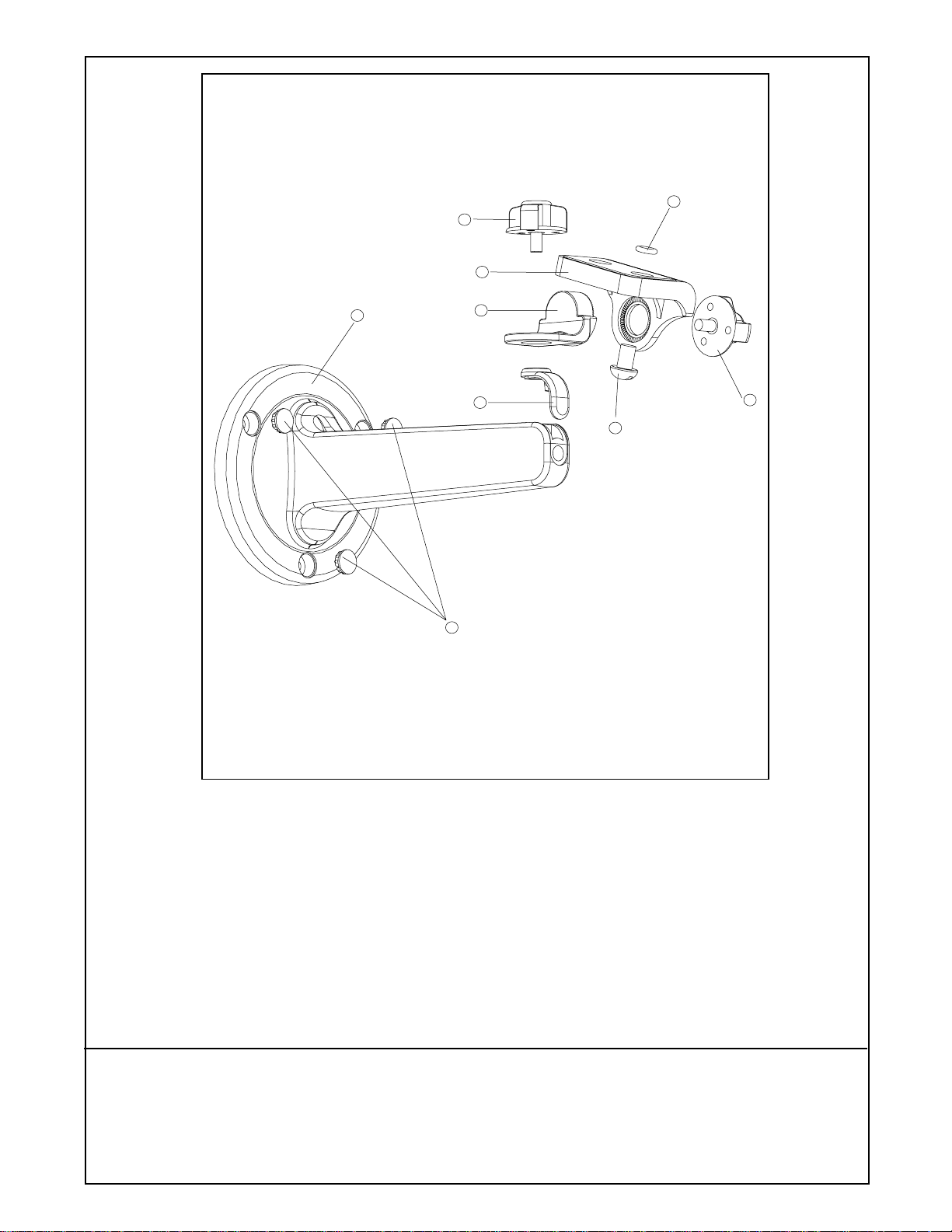
I
G
D
A
E
C
H
B
F
Figure 7
Description Part number
Qty.
A PUM8 Bracket Body 30-VL1332 1
B Hole Covers 30-VL1334 3
C Front Cover 30-VL1333 1
D Tilt Mount 30-VL1336 1
E Pan Mount 30-VL1335 1
F Tilt Adjustment Knob 30-VL1337 1
G Pan Adjustment Knob 30-VL1476 1
H 1/4-20x1/2" Screw 90-BTSRO1 1
I O-ring 96-RSORNG 1
- 4 -
 Loading...