

Page 1
Operating Instructions
Functional Manual
DLPTM Projector
Model No.
PT-RZ370EA
PT-RW330EA
Commercial Use
Thank you for purchasing this Panasonic product.
■ Before operating this product, please read the instructions carefully and save this manual
for future use.
■ Before using your projector, be sure to read “Read this rst!” (x pages 2 to 8).
ENGLISH
TQBJ0492-1
Page 2
Read this rst!
Read this rst!
WARNING: THIS APPARATUS MUST BE EARTHED.
WARNING: To prevent damage which may result in re or shock hazard, do not expose this appliance to rain
or moisture.
This device is not intended for use in the direct eld of view at visual display workplaces. To avoid
incommoding reexions at visual display workplaces this device must not be placed in the direct
eld of view.
The equipment is not intended for used at a video workstation in compliance BildscharbV.
The sound pressure level at the operator position is equal or less than 70 dB (A) according to ISO 7779.
WARNING:
1. Remove the plug from the mains socket when this unit is not in use for a prolonged period of time.
2. To prevent electric shock, do not remove cover. No user serviceable parts inside. Refer servicing to qualied
service personnel.
3. Do not remove the earthing pin on the mains plug. This apparatus is equipped with a three prong
earthingtype mains plug. This plug will only t an earthing-type mains socket. This is a safety feature. If you
are unable to insert the plug into the mains socket, contact an electrician. Do not defeat the purpose of the
earthing plug.
WARNING:
This is a class A product. In a domestic environment this product may cause radio interference in which case
the user may be required to take adequate measures.
CAUTION: To assure continued compliance, follow the attached installation instructions, which include
using the provided power cord and shielded interface cables when connecting to computer or
peripheral device. If you use serial port to connect PC for external control of projector, you must
use a commercial RS-232C serial interface cable with ferrite core. Any unauthorized changes or
modications to this equipment will void the user’s authority to operate.
Notice on laser
This projector is the Class 1 laser product that complies with IEC 60825-1.
Importer’s name and address within the European Union
Panasonic Marketing Europe GmbH
Panasonic Testing Center
Winsbergring 15, 22525 Hamburg, Germany
2 - ENGLISH
Page 3
Read this rst!
IMPORTANT: THE MOULDED PLUG (U.K. only)
FOR YOUR SAFETY, PLEASE READ THE FOLLOWING TEXT CAREFULLY.
This appliance is supplied with a moulded three pin mains plug for your safety and convenience. A 13 amp fuse
is tted in this plug. Should the fuse need to be replaced, please ensure that the replacement fuse has a rating
of 13 amps and that it is approved by ASTA or BSI to BS1362.
Check for the ASTA mark
or the BSI mark on the body of the fuse.
If the plug contains a removable fuse cover, you must ensure that it is retted when the fuse is replaced. If you
lose the fuse cover, the plug must not be used until a replacement cover is obtained. A replacement fuse cover
can be purchased from an Authorised Service Center.
If the tted moulded plug is unsuitable for the mains socket in your home, then the fuse should be
removed and the plug cut off and disposed of safely. There is a danger of severe electrical shock if the
cut off plug is inserted into any 13 amp socket.
If a new plug is to be
tted, please observe the wiring code as shown below.
If in any doubt, please consult a qualied electrician.
WARNING: THIS APPLIANCE MUST BE EARTHED.
IMPORTANT: The wires in this mains lead are coloured in accordance with the following code:
Green - and - Yellow: Earth
Blue: Neutral
Brown: Live
As the colours of the wire in the mains lead of this appliance may not correspond with the coloured markings
identifying the terminals in your plug, proceed as follows.
The wire which is coloured GREEN plug which is marked with the letter E or by the Earth symbol
AND - YELLOW must be connected to the terminal in the
or coloured GREEN or GREEN -
AND - YELLOW.
The wire which is coloured BLUE must be connected to the terminal in the plug which is marked
with the letter N or coloured BLACK.
The wire which is coloured BROWN must be connected to the terminal in the plug which is marked
with the letter L or coloured RED.
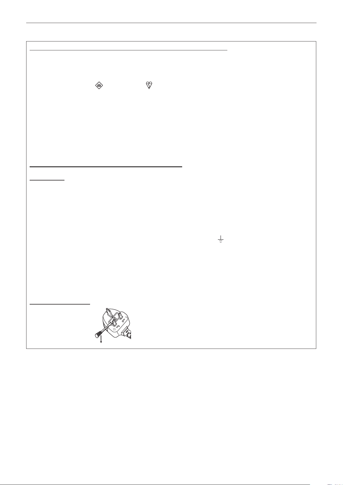
How to replace the fuse: Open the fuse compartment with a screwdriver and replace the fuse.
BS1363/A
N
13A250V
HE-8
L
ASA
ENGLISH - 3
Page 4

Read this rst!
WARNING:
POWER
The wall outlet or the circuit breaker shall be installed near the equipment and shall be easily accessible
when problems occur. If the following problems occur, cut off the power supply immediately.
Continued use of the projector in these conditions will result in re or electric shock.
zIf foreign objects or water get inside the projector, cut off the power supply.
zIf the projector is dropped or the cabinet is broken, cut off the power supply.
zIf you notice smoke, strange smells or noise coming from the projector, cut off the power supply.
Please contact an Authorized Service Center for repairs, and do not attempt to repair the projector yourself.
During a thunderstorm, do not touch the projector or the cable.
Electric shocks can result.
Do not do anything that might damage the power cord or the power plug.
If the power cord is used while damaged, electric shocks, short-circuits or re will result.
zDo not damage the power cord, make any modications to it, place it near any hot objects, bend it
excessively, twist it, pull it, place heavy objects on top of it or wrap it into a bundle.
Ask an Authorized Service Center to carry out any repairs to the power cord that might be necessary.
Completely insert the power plug into the wall outlet and the power connector into the projector terminal.
If the plug is not inserted correctly, electric shocks or overheating will result.
zDo not use plugs which are damaged or wall outlets which are coming loose from the wall.
Clean the power plug regularly to prevent it from becoming covered in dust.
Failure to observe this will cause a re.
zIf dust builds up on the power plug, the resulting humidity can damage the insulation.
Pull the power plug out from the wall outlet and wipe it with a dry cloth regularly.
Do not handle the power plug and power connector with wet hands.
Failure to observe this will result in electric shocks.
Do not overload the wall outlet.
If the power supply is overloaded (ex., by using too many adapters), overheating may occur and re will result.
ON USE/INSTALLATION
Do not place the projector on soft materials such as carpets or sponge mats.
Doing so will cause the projector to overheat, which can cause burns, re or damage to the projector.
Do not set up the projector in humid or dusty places or in places where the projector may come into
contact with oily smoke or steam, ex. a bathroom.
Using the projector under such conditions will result in re, electric shocks or deterioration of components.
Deterioration of components (such as ceiling mount brackets) may cause the projector which is mounted on the
ceiling to fall down.
Do not install this projector in a place which is not strong enough to take the full weight of the projector
or on top of a surface which is sloped or unstable.
Failure to observe this will cause projector to fall down or tip over the projector, and severe injury or damage
could result.
4 - ENGLISH
Page 5

Read this rst!
WARNING:
Do not cover the air intake/exhaust ports or place anything within 500 mm (20") of them.
Doing so will cause the projector to overheat, which can cause re or damage to the projector.
zDo not place the projector in narrow, badly ventilated places.
zDo not place the projector on cloth or papers, as these materials could be drawn into the air intake port.
Do not look at the light emitted from the lens while the projector is being used.
Doing so can cause loss of sight.
zStrong light is emitted from the projector’s lens. Do not directly look at this light.
Do not expose your eyes and skin to the projection light while the projector is being used.
Possibly hazardous optical radiation is emitted from this product, causing damage to your eyes and skin.
zBe especially careful not to let young children look into the lens. In addition, turn off the power and
disconnect the power plug when you are away from the projector.
Never attempt to remodel or disassemble the projector.
High voltages can cause re or electric shocks.
zFor any inspection, adjustment and repair work, please contact an Authorized Service Center.
Doing so may cause exposure to dangerous laser radiation.
zThe laser module is built in this projector. Follow procedures specied in the Operating Instructions to make
operations and adjustments.
Do not allow metal objects, ammable objects, or liquids to enter inside of the projector. Do not allow
the projector to get wet.
Doing so may cause short circuits or overheating, and result in re, electric shock, or malfunction of the
projector.
zDo not place containers of liquid or metal objects near the projector.
zIf liquid enters inside of the projector, consult your dealer.
zParticular attention must be paid to children.
Use the ceiling mount bracket specied by Panasonic.
Using the ceiling mount bracket other than the specied one will result in falling accidents.
zAttach the supplied safety cable to the ceiling mount bracket to prevent the projector from falling down.
Installation work (such as ceiling mount bracket) should only be carried out by a qualied technician.
If installation is not carried out and secured correctly it can cause injury or accidents, such as electric shocks.
zDo not use anything other than an authorized ceiling mount bracket.
zBe sure to use the provided accessory wire with an eye bolt as an extra safety measure to prevent the
projector from falling down. (Install in a different location to the ceiling mount bracket.)
ENGLISH - 5
Page 6

Read this rst!
WARNING:
ACCESSORIES
Do not use or handle the batteries improperly, and refer to the following.
Failure to observe this will cause burns, batteries to leak, overheat, explode or catch re.
zUse AA/R6/LR6 batteries.
zDo not use unspecied batteries.
zDo not use chargeable batteries.
zDo not disassemble dry cell batteries.
zDo not heat the batteries or place them into water or re.
zDo not allow the + and – terminals of the batteries to come into contact with metallic objects such as
necklaces or hairpins.
zDo not store or carry batteries together with metallic objects.
zStore the batteries in a plastic bag and keep them away from metallic objects.
zMake sure the polarities (+ and –) are correct when inserting the batteries.
zDo not use a new battery together with an old battery or mix different types of batteries.
zDo not use batteries with the outer cover peeling away or removed.
If the battery uid leaks, do not touch it with bare hands, and take the following measures if necessary.
zBattery uid on your skin or clothing could result in skin inammation or injury.
Rinse with clean water and seek medical advice immediately.
zBattery uid coming in contact with your eyes could result in loss of sight.
In this case, do not rub your eyes. Rinse with clean water and seek medical advice immediately.
Do not use the supplied power cord with devices other than this projector.
zUsing the supplied power cord with devices other than this projector may cause short circuits or
overheating, and result in electric shock or re.
Remove the depleted batteries from the remote control promptly.
zLeaving them in the unit may result in uid leakage, overheating, or explosion of the batteries.
6 - ENGLISH
Page 7

Read this rst!
CAUTION:
POWER
When disconnecting the power cord, be sure to hold the power plug and power connector.
If the power cord itself is pulled, the lead will become damaged, and re, short-circuits or serious electric shocks
will result.
When not using the projector for an extended period of time, disconnect the power plug from the wall
outlet.
Failure to do so may result in re or electric shock.
Disconnect the power plug from the wall outlet before carrying out any cleaning.
Failure to do so may result in electric shock.
ON USE/INSTALLATION
Do not place heavy objects on top of the projector.
Failure to observe this will cause the projector to become unbalanced and fall, which could result in damage or
injury. The projector will be damaged or deformed.
Do not put your weight on this projector.
You could fall or the projector could break, and injury will result.
zBe especially careful not to let young children stand or sit on the projector.
Do not place the projector in extremely hot locations.
Doing so will cause the outer casing or internal components to deteriorate, or result in re.
zTake particular care in locations exposed to direct sunlight or near stoves.
Do not place your hands or other objects close to the air exhaust port.
Doing so will cause burns or damage your hands or other objects.
zHeated air comes out of the air exhaust port. Do not place your hands or face, or objects which cannot
withstand heat close to this port.
Always disconnect all cables before moving the projector.
Moving the projector with cables still attached can damage the cables, which will cause re or electric shocks to
occur.
When mounting the projector on the ceiling, keep mounting screws and power cord from contact with
metal parts inside the ceiling.
Contact with metal parts inside the ceiling can cause electric shocks.
ACCESSORIES
Ask your dealer about cleaning inside the projector every 20 000 hours of usage as an estimated
duration.
Continuous use while dust is accumulated inside the projector may result in re.
zFor cleaning fee, ask your dealer.
When not using the projector for an extended period of time, remove the batteries from the remote
control.
Failure to observe this will cause the batteries to leak, overheat, catch re or explode, which may result in re
or contamination of surrounding area.
ENGLISH - 7
Page 8
To remove the battery
Remote Control Battery
Read this rst!
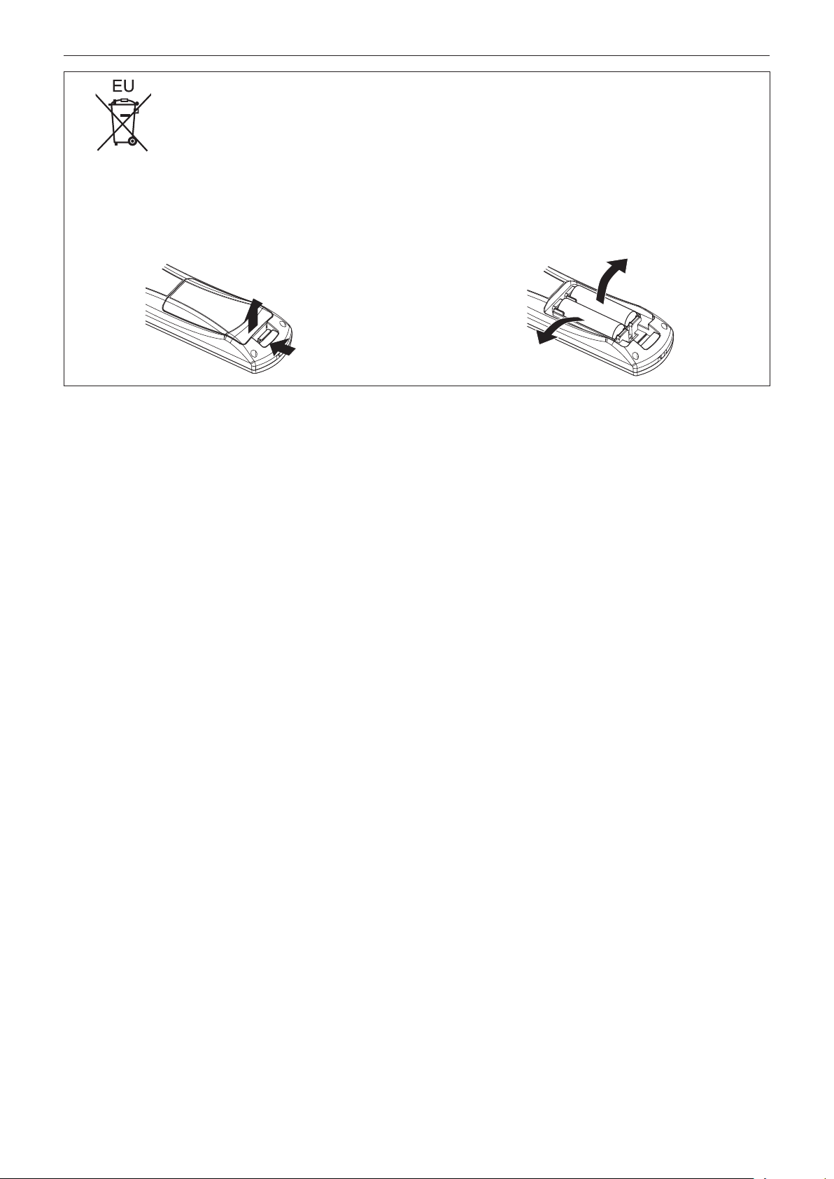
1. Press the guide and lift the cover.
(ii)
(i)
2. Remove the batteries.
8 - ENGLISH
Page 9

rTrademarks
fSOLID SHINE is a trademark of Panasonic Corporation.
fWindows
United States and other countries.
fMac, Mac OS, OS X, and Safari are registered trademarks of Apple Inc. in the United States and other countries.
fPJLink
fHDMI, the HDMI Logo, and High-Denition Multimedia Interface are trademarks or registered trademarks of HDMI Licensing
LLC in the United States and other countries.
fVGA and XGA are trademarks of International Business Machines Corporation in the United States.
fSVGA is a trademark or registered trademark of Video Electronics Standards Association.
fRoomView and Crestron RoomView are registered trademarks of Crestron Electronics, Inc.
Crestron Connected and Fusion RV are trademarks of Crestron Electronics, Inc.
fAdobe Flash Player is a trademark or registered trademark of Adobe Systems Inc. in the United Stated and/or in other
countries.
fAll other names, company names, and product names mentioned in this manual are trademarks or registered trademarks of
their respective owners.
Please note that the ® and TM symbols are not specied in this manual.
®
, Windows Vista®, and Internet Explorer® are registered trademarks or trademarks of Microsoft Corporation in the
TM
is a registered trademark or pending trademark in Japan, the United States, and other countries and regions.
rIllustrations in this manual
fIllustrations of the projector, screen, and other parts may vary from the actual product.
rReference pages
fReference pages in this manual are indicated as (x page 00).
rTerm
fIn this manual, the “Wireless remote control unit” accessory is referred to as “Remote control”.
ENGLISH - 9
Page 10

Features of the Projector
Easy setup and improved
serviceability
▶A highly exible setup is achieved with a 2x
zoom lens, wide range of the lens shift, and
DIGITAL LINK (x page 16) compatibility.
Long-life reliability achieved
▶The reliability is enhanced through the
power-driving and unique cooling control
system that maximizes the life of the light
source and complete hermeticity of the
light source unit, achieving the long-time
maintenance-free projector.
Quick Steps
For details, refer to the corresponding pages.
1. Set up the projector.
(x page 25)
c
2. Connect with external devices.
(x page 28)
c
3. Connect the power cord.
(x page 33)
c
4. Switch on the projector.
Energy conservation achieved
through the ECO function
▶The function to reduce power consumption
is installed, which is optimizing the light
source power according to the brightness
of the surroundings, input signal, and video
mute status.
(x page 34)
c
5. Make initial settings.
(x page 19)
fTake this step when you switch on the power for the rst
time after purchasing the projector.
c
6. Select the input signal.
(x page 36)
c
7. Adjust the image.
(x page 36)
10 - ENGLISH
Page 11

Contents
Contents
Read this rst! ............................................2
Chapter 1 Preparation
Precautions for use ................................................. 14
Cautions when transporting .................................. 14
Cautions when installing ....................................... 14
Security ................................................................ 15
DIGITAL LINK ....................................................... 16
Disposal ................................................................ 16
Cautions on use ................................................... 16
Accessories .......................................................... 17
Optional accessories ............................................ 18
Start-up display ....................................................... 19
Initial setting (display language) ........................... 19
Initial setting (projector setup) .............................. 19
About your projector ............................................... 20
Remote control ..................................................... 20
Projector body ...................................................... 21
Using the remote control ........................................ 23
Inserting and removing the batteries .................... 23
Setting the remote control ID numbers ................. 23
Chapter 2 Getting Started
Setting up ................................................................. 25
Projection method ................................................ 25
Parts for ceiling mount (optional) .......................... 25
Screen size and throw distance ........................... 26
Adjusting adjustable feet ...................................... 27
Connecting ............................................................... 28
Before connecting ................................................ 28
Connecting example: AV equipment .................... 29
Connecting example: Computers ......................... 30
Connecting example: Twisted-pair-cable
transmitter ......................................................... 30
Chapter 3 Basic Operations
Switching on/off the projector ................................ 33
Connecting the power cord .................................. 33
Power indicator ..................................................... 33
Switching on the projector .................................... 34
Making adjustments and selections ..................... 35
Switching off the projector .................................... 35
Projecting ................................................................. 36
Selecting the input signal ..................................... 36
Adjusting the image .............................................. 36
Adjustment range by the lens position shift
(optical shift) ...................................................... 37
Be sure to read “Read this rst!” from page 2.
Operating with the remote control ......................... 38
Using the AV mute function .................................. 38
Using the Freeze function .................................... 38
Switching the input ............................................... 39
Using the Automatic setup function ...................... 39
Using the Function button .................................... 40
Using the ECO management function .................. 40
Adjusting the volume ............................................ 40
Chapter 4 Settings
Menu navigation ...................................................... 42
Navigating through the menu ............................... 42
Main menu ............................................................ 43
Sub-menu ............................................................. 44
[PICTURE] menu ...................................................... 47
[PICTURE MODE] ................................................ 47
[CONTRAST] ........................................................ 47
[BRIGHTNESS] .................................................... 48
[COLOR] ............................................................... 48
[TINT] ................................................................... 48
[COLOR TEMPERATURE] ................................... 48
[DAYLIGHT VIEW] ................................................ 50
[SHARPNESS] ..................................................... 50
[NOISE REDUCTION] .......................................... 50
[SYSTEM SELECTOR] ........................................ 51
sRGB-compliant video .......................................... 51
[POSITION] menu .................................................... 52
[SHIFT] ................................................................. 52
[ASPECT] ............................................................. 53
[ZOOM] ................................................................. 53
[CLOCK PHASE] .................................................. 54
[KEYSTONE] ........................................................ 55
[ADVANCED MENU] menu ...................................... 56
[DIGITAL CINEMA REALITY] ............................... 56
[BLANKING] ......................................................... 56
[INPUT RESOLUTION] ........................................ 57
[CLAMP POSITION] ............................................. 57
[FRAME RESPONSE] .......................................... 58
[RASTER POSITION] ........................................... 58
[DISPLAY LANGUAGE] menu ................................. 59
Changing the display language ............................ 59
ENGLISH - 11
Page 12

Contents
[DISPLAY OPTION] menu ........................................ 60
[COLOR MATCHING] ........................................... 60
[SCREEN SETTING] (only for PT-RW330EA) ..... 61
[AUTO SIGNAL] ................................................... 62
[AUTO SETUP]..................................................... 62
[COMPUTER IN] .................................................. 62
[DVI-I IN] ............................................................... 63
[HDMI IN] .............................................................. 64
[DIGITAL LINK IN] ................................................ 64
[ON-SCREEN DISPLAY] ...................................... 64
[CLOSED CAPTION SETTING] (NTSC input
only) ................................................................... 66
[BACK COLOR] .................................................... 67
[STARTUP LOGO] ................................................ 67
[SUB MEMORY LIST] .......................................... 68
[FREEZE] ............................................................. 68
[AV MUTE] ............................................................ 69
[PROJECTOR SETUP] menu .................................. 70
[PROJECTOR ID] ................................................. 70
[PROJECTION METHOD] .................................... 70
[COOLING CONDITION] ...................................... 71
[ECO MANAGEMENT] ......................................... 71
[SCHEDULE] ........................................................ 73
[INITIAL STARTUP] .............................................. 75
[STARTUP INPUT SELECT] ................................ 75
[DIGITAL LINK INPUT] ......................................... 76
[RS-232C] ............................................................. 76
[FUNCTION BUTTON] ......................................... 78
[AUDIO SETTING] ............................................... 78
[STATUS] .............................................................. 80
[DATE AND TIME] ................................................ 80
[SAVE ALL USER DATA] ...................................... 81
[LOAD ALL USER DATA] ..................................... 81
[INITIALIZE] .......................................................... 82
[SERVICE PASSWORD] ...................................... 82
[TEST PATTERN] menu ........................................... 83
[TEST PATTERN] ................................................. 83
[SIGNAL LIST] menu ............................................... 84
Registering a signal to the list .............................. 84
Renaming the registered signal ............................ 84
Deleting the registered data ................................. 85
[SECURITY] menu ................................................... 86
[SECURITY PASSWORD] .................................... 86
[SECURITY PASSWORD CHANGE] ................... 86
[TEXT DISPLAY] .................................................. 87
[TEXT CHANGE] .................................................. 87
[MENU LOCK] ...................................................... 87
[MENU LOCK PASSWORD] ................................ 87
[CONTROL DEVICE SETUP] ............................... 88
[NETWORK] menu ................................................... 89
[DIGITAL LINK MODE] ......................................... 89
[DIGITAL LINK SETUP] ........................................ 89
[DIGITAL LINK STATUS] ...................................... 90
[NETWORK SETUP] ............................................ 91
[NETWORK CONTROL] ...................................... 91
[NETWORK STATUS] .......................................... 92
Network connections ............................................ 92
Connecting to a twisted-pair-cable transmitter ..... 93
Accessing from the web browser ......................... 94
[DIGITAL LINK] menu ............................................ 108
Chapter 5 Maintenance
Light source/temperature indicator ..................... 110
Managing the indicated problems .......................110
Maintenance ........................................................... 112
Before maintaining the projector .........................112
Maintenance ........................................................112
Troubleshooting .................................................... 113
Chapter 6 Appendix
Technical information ........................................... 116
PJLink protocol ....................................................116
Control commands via LAN .................................117
<SERIAL IN> terminal .........................................119
Menu lock password ........................................... 121
List of compatible signals ................................... 122
Specications ........................................................ 124
Dimensions ............................................................ 126
Ceiling mount bracket safeguards....................... 127
Index ....................................................................... 128
12 - ENGLISH
Page 13

Chapter 1
This chapter describes things you need to know or check before using the projector.
Preparation
ENGLISH - 13
Page 14

Chapter 1 Preparation — Precautions for use
Precautions for use
Cautions when transporting
fWhen transporting the projector, hold it securely by its bottom and avoid excessive vibration and impacts. Doing so may
damage the internal components and result in malfunctions.
fDo not transport the projector with the adjustable feet extended. Doing so may damage the adjustable feet.
Cautions when installing
rDo not set up the projector outdoors.
The projector is designed for indoor use only.
rDo not set up the projector in the following locations.
fPlaces where vibration and impacts occur such as in a car or vehicle: Doing so may cause damage to internal components
or malfunction.
fNear the exhaust of an air conditioner: Depending on the conditions of use, the screen may uctuate in rare cases due
to the hot air from the air exhaust port or the heated or cooled air. Make sure that the exhaust from the projector or other
equipment, or the air from the air conditioner does not blow toward the front of the projector.
fNear lights (studio lamps, etc.) and other locations with severe temperature uctuations (“Operating environment”
(x page 125)): Placing the projector in these locations may result in malfunctions and the deformation of the outer case.
fNear high-voltage power lines or near motors: Doing so may interfere with the operation of the projector.
fPlace where there is high-power laser equipment: Directing a laser beam onto the lens surface causes damage to the DLP
chips.
rBe sure to ask a specialized technician or your dealer when installing the product to a
ceiling.
The optional ceiling mount bracket is required.
Model No.: ET-PKR100H (for high ceilings), ET-PKR100S (for low ceilings)
rAsk a qualied technician or your dealer to install the cable wiring for DIGITAL LINK
connection.
Image and sound may be disrupted if cable transmission characteristics can not be obtained due to inadequate installation.
rThe projector may not work properly due to strong radiowave from the broadcast
station or the radio.
If there is any facility or equipment, which outputs strong radiowave, near the installation location, install the projector at a
location sufciently far from the source of the radiowave. Or, wrap the LAN cable connected to the <DIGITAL LINK/LAN>
terminal by using a piece of metal foil or a metal pipe, of which is grounded at both ends.
rLens focus
The high clarity projection lens is thermally affected by the light from the light source, making the focus unstable in the period
just after switching on the power. Wait at least 30 minutes with the image projected before adjusting the lens focus.
rDo not install the projector at elevations of 2 700 m (8 858') or higher above sea level.
Doing so may shorten the life of the internal components and result in malfunctions.
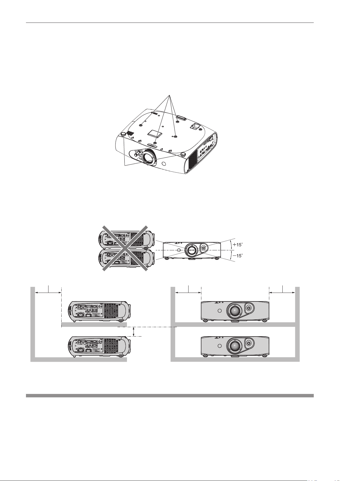
rDo not use the projector tilted to the right or left.
Using the projector at a vertical angle that exceeds 15° may reduce product life or result in malfunction.
rWhen installing and using the projector at an angle that exceeds 30° vertically, set
[COOLING CONDITION] (x page 71).
Failure to observe this will result in malfunctions or shorten the life of the internal components.
14 - ENGLISH
Page 15
Chapter 1 Preparation — Precautions for use
6FUHZKROHVIRUFHLOLQJPRXQW0
PPRUORQJHU
PPRUORQJHU PPRUORQJHU
rCautions when setting up the projector
fTo install and use the projector via a method that does not use the adjustable feet in a oor standing installation, x the
projector using the four screw holes for ceiling mounting (as shown in the gure).
(Screw diameter: M4, tapping depth inside the set: 10 mm (13/32"), torque: 1.25 ± 0.2 N·m)
Make a clearance of at least 12 mm (15/32") between the projector bottom and setting surface by inserting spacers (metallic)
etc. between them.
fUse the adjustable feet only for the oor standing installation and for adjusting the angle. Using it for other purposes may
damage the set.
$GMXVWDEOHIHHW
7KHSRVLWLRQVRIVFUHZKROHVIRUFHLOLQJPRXQWDQGDGMXVWDEOHIHHW
fDo not stack projectors on top of each other.
fDo not block the ventilation ports (intake and exhaust) of the projector.
fPrevent hot and cool air from the air conditioning system to blow directly to the ventilation ports (intake and exhaust) of the
projector.
PPRUORQJHU
fDo not install the projector in a conned space.
When it is necessary to install the projector in a conned space, install the air conditioning or ventilation separately. Exhaust
heat may accumulate when the ventilation is not enough, triggering the protection circuit of the projector.
Security
When using this product, take safety measures against the following incidents.
fPersonal information being leaked via this product
fUnauthorized operation of this product by a malicious third party
fInterfering or stopping of this product by a malicious third party
Take sufcient security measures. (x pages 86, 104)
fMake your password difcult to guess as much as possible.
fChange your password periodically.
ENGLISH - 15
Page 16

Chapter 1 Preparation — Precautions for use
fPanasonic Corporation or its afliate companies will never ask for your password directly. Do not divulge your password in
case you receive such inquiries.
fThe connecting network must be secured by a rewall, etc.
fSet a password for the web control and restrict the users who can log in.
DIGITAL LINK
“DIGITAL LINK” is a technology that uses a twisted-pair-cable to transmit video, audio, Ethernet, and serial control signals.
The projector supports the optional digital interface box (Model No.: ET-YFB100G), and the “XTP transmitter” of Extron
Electronics. For twisted-pair-cable transmitter of other manufacturers of which the operation has been veried with the
DIGITAL LINK compatible projector, refer to Panasonic website (http://panasonic.net/avc/projector/). Note that the verication
for devices of other manufacturers has been made for the items set by Panasonic Corporation, and not all the operations have
been veried. For operation or performance problems caused by the devices of other manufacturers, contact the respective
manufacturers.
Disposal
To dispose of the product, ask your local authorities or dealer for correct methods of disposal.
Cautions on use
rTo get a good picture quality
fIn order to view a beautiful image in higher contrast, prepare an appropriate environment. Draw curtains or blinds over
windows and turn off any lights near the screen to prevent outside light or light from indoor lamps from shining onto the
screen.
fThe high clarity projection lens is thermally affected by the light from the light source, making the focus unstable in the period
just after switching on the power. The focus stabilizes when an image is projected continuously for 30 minutes or more.
rDo not touch the surface of the projection lens with your bare hands.
If the surface of the projection lens becomes dirty from ngerprints or anything else, this will be magnied and projected onto
the screen.
rDLP chips
fThe DLP chips are precision-made. Note that in rare cases, pixels of high precision could be missing or always lit. Note that
such phenomena does not indicate malfunction.
fDirecting a high-power laser beam onto the lens surface can damage the DLP chips.
rLight source
The light source of the projector uses LED and lasers, and has the following characteristics.
fThe luminance of the light source will decrease by duration of usage.
The usage time until when the luminance of the light source decreases by half is approximately 20 000 hours. 20 000 hours
is the estimated duration, and it varies depending on individual differences and usage conditions.
If the light source goes off or the brightness reduces noticeably, ask your dealer about replacement of the light source unit.
rComputer and external device connections
fWhen connecting a computer or an external device, use power cords and shielded cables following instructions in this
manual.
fUse a commercial DVI-D cable with a ferrite core.
16 - ENGLISH
Page 17
Chapter 1 Preparation — Precautions for use
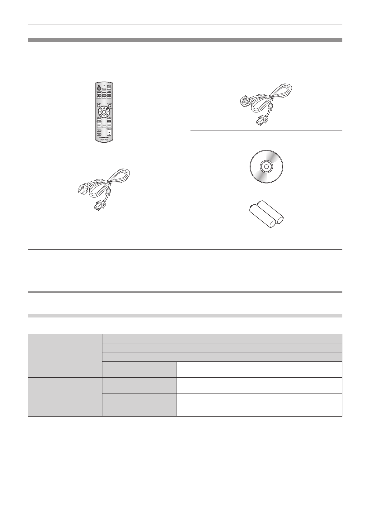
Accessories
Make sure that the following accessories are provided with your projector. Numbers enclosed in < > show the number of
accessories.
Wireless remote control unit <1>
(N2QAYB000812)
Power cord <1>
(TXFSX01RXQZ)
Attention
Power cord <1>
(TXFSX01RXRZ)
CD-ROM <1>
(TXFQB02VLF1)
AA/R6 or AA/LR6 battery <2>
(For remote control unit)
fAfter unpacking the projector, discard the power cord cap and packaging material properly.
fUse the supplied power cord only with the projector.
fFor missing accessories, consult your dealer.
fStore small parts in an appropriate manner, and keep them away from small children.
Note
fThe model numbers of accessories are subject to change without prior notice.
Contents of the supplied CD-ROM
The contents of the supplied CD-ROM are as follows.
Instruction/list (PDF) Operating Instructions – Functional Manual
Multi Projector Monitoring & Control Software Operation Manual
Logo Transfer Software Operating Instructions
List of Compatible Projector
Models
Software Multi Projector Monitoring &
Control Software (Windows)
Logo Transfer Software
(Windows)
This is a list of projectors that are compatible with the software
contained in the CD-ROM and their restrictions.
This software allows you to monitor and control multiple
projectors connected to the LAN.
This software allows you to create original images, such as
company logos to be displayed when projection starts, and
transfer them to the projector.
ENGLISH - 17
Page 18

Optional accessories
Chapter 1 Preparation — Precautions for use
Optional accessories
(product name)
Ceiling mount bracket ET-PKR100H (for high ceilings), ET-PKR100S (for low ceilings)
Digital interface box ET-YFB100G
Note
fThe model numbers of optional accessories are subject to change without prior notice.
Model No.
18 - ENGLISH
Page 19
Chapter 1 Preparation — Start-up display
Start-up display
The initial setting screen is displayed when the projector is switched on for the rst time after purchase as well as when [ALL USER DATA]
(x page 82) in [INITIALIZE] is executed. Set them in accordance with circumstances.
In other occasions, you can change the settings by menu operations.
Note
fWhen the projector is used for the rst time, you may be required to adjust the lens zoom ring and focus ring of the projector (x page 21)
to display the menu screen clearly.
Refer to “Adjusting the image” (x page 36) for details.
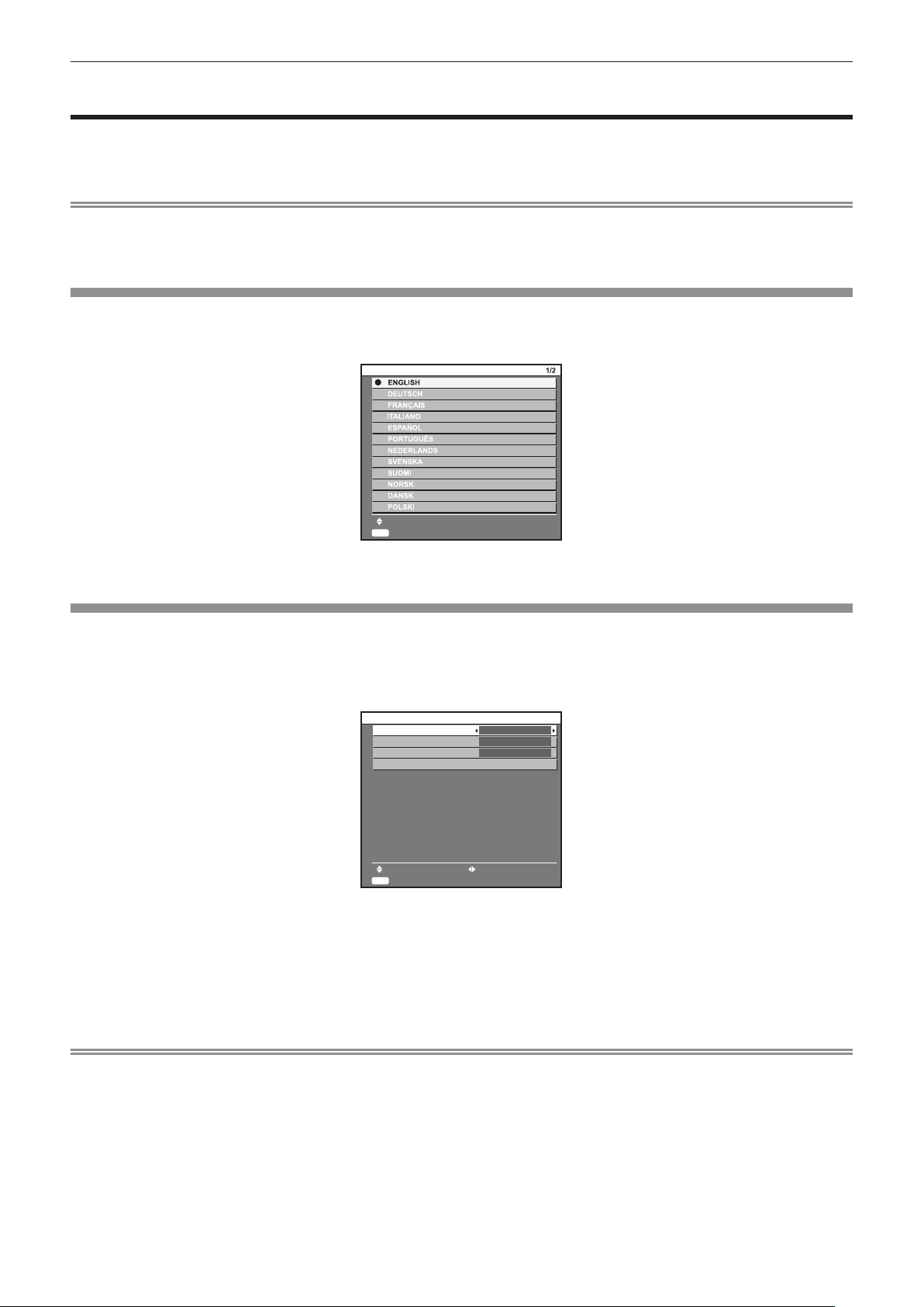
Initial setting (display language)
Select the language to show on the screen. (x page 59)
Press as to select the display language.
1)
,1,7,$/6(77,1*
6(/(&7
(17(5
6(7
Press the <ENTER> button to proceed to the initial setting.
2)
Initial setting (projector setup)
Set each item.
Press as to select an item.
1)
Press qw to switch the setting.
2)
,1,7,$/6(77,1*
352-(&7,210(7+2'
&22/,1*&21',7,21
6&5((1)250$7
6&5((1326,7,21
0(186(/(&7 &+$1*(
(17(5
6(7
fRefer to the following page for details of each item.
[PROJECTION METHOD] (x page 70)
[COOLING CONDITION] (x page 71)
[SCREEN FORMAT] (x page 61)
[SCREEN POSITION] (x page 61)
)5217)/225
)/2256(77,1*
Press the <ENTER> button.
3)
fFix the setting value to complete the initial setting.
Note
fIf you press the <RETURN> button in the initial setting (display language) screen, you can go back to the initial setting (display language)
screen.
f[SCREEN FORMAT] and [SCREEN POSITION] can only be set on PT-RW330EA.
fTo continue operations after completed the initial setting (projector setup), refer to “Selecting the input signal” (x page 36).
fBy default, the time zone of the projector is set to +09:00 (Japan and Korean Standard Time). Change the setting in the [PROJECTOR
SETUP] menu → [DATE AND TIME] → [TIME ZONE] to the time zone of the region where you use the projector.
ENGLISH - 19
Page 20
Chapter 1 Preparation — About your projector
)URQW 7RS
About your projector
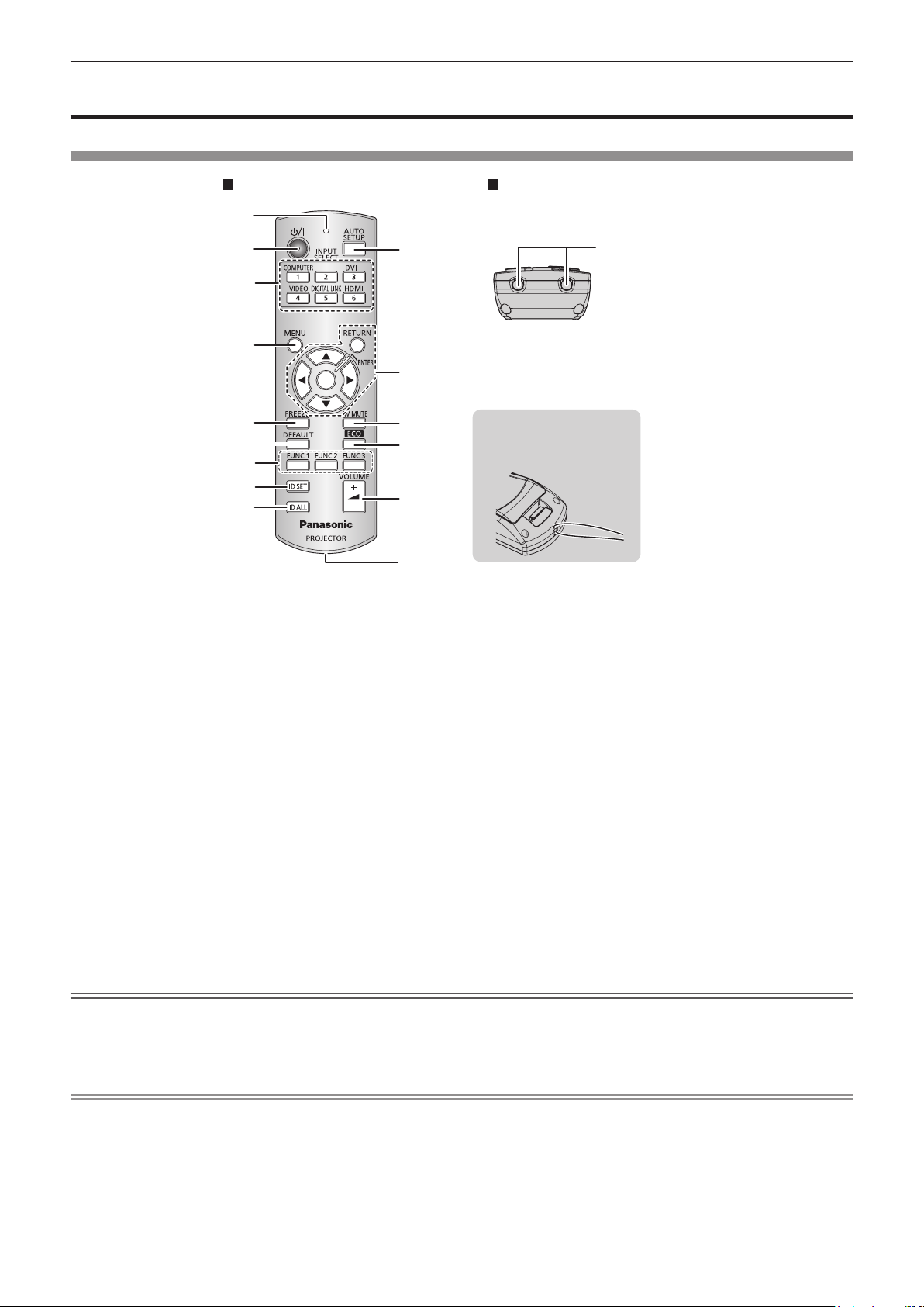
Remote control
1 Remote control indicator
Flashes if any button in the remote control is pressed.
2 Power <v/b> button
Sets the projector to the standby mode when the <MAIN
POWER> switch on the projector is set to <ON>. Also sets the
projector in projection mode when the power is switched off
(standby mode).
3 Input selection (<COMPUTER>, <DVI-I>, <VIDEO>, <DIGITAL
LINK>, <HDMI>) buttons
Switches the input signal to project. (x page 39)
Also used to set the ID number of the remote control and
security password. (x page 23)
4 <MENU> button
Displays the main menu. (x page 42)
5 <FREEZE> button
Used to pause a video and mute the audio. (x page 38)
6 <DEFAULT> button
Resets the content of the sub-menu to the factory default.
(x page 43)
7 <FUNC1> to <FUNC3> buttons
You can assign a frequently used operation as a shortcut button.
(x page 40)
Attention
$WWDFKDVWUDSDFFRUGLQJWR
XVDJHFRQGLWLRQ
8 <ID SET> button
Sets the ID number of the remote control to use for a system
using multiple projectors. (x page 23)
9 <ID ALL> button
Use to simultaneously control all the projectors with one remote
control for a system using multiple projectors. (x page 23)
10 <AUTO SETUP> button
Automatically adjusts the image display position while projecting
the image.
[PROGRESS] is displayed on the screen while the image is
adjusted automatically. (x page 39)
11
asqw
Used to navigate through the menu screen.
Also used to enter a [SECURITY] password or character input.
12 <AV MUTE> button
Use to temporarily turn off the audio and video. (x page 38)
13 <ECO> button
Displays the setting screen related to ECO management.
(x page 40)
14 <VOLUME+>/<VOLUME
Adjusts the audio output volume. (x page 40)
15 Strap hole
16 Remote control signal transmitter
buttons/<RETURN> button/<ENTER> button
-
> button
fDo not drop the remote control.
fAvoid contact with liquids or moisture.
fDo not attempt to modify or disassemble the remote control.
fWhen attaching the strap to the remote control, hold the strap to prevent it from swinging.
Note
fThe remote control can be used within a distance of about 15 m (49'2") if pointed directly at the remote control receiver. The remote control
can control at angles of up to ±15° vertically and ±30° horizontally, but the effective control range may be reduced.
fIf there are any obstacles between the remote control and the remote control signal receiver, the remote control may not operate properly.
fThe signal will be reected off the screen. However, the operating range may be limited from light reection loss due to the screen material.
fIf the remote control signal receiver directly receives strong light, such as uorescent light, the remote control may not operate properly. Use
it in a place distant from the light source.
fThe power indicator <ON (G)/STANDBY (R)> will ash if the projector receives a remote control signal.
20 - ENGLISH
Page 21
Projector body
)URQW 6LGH
%RWWRP
Chapter 1 Preparation — About your projector
5HDU
)URQW
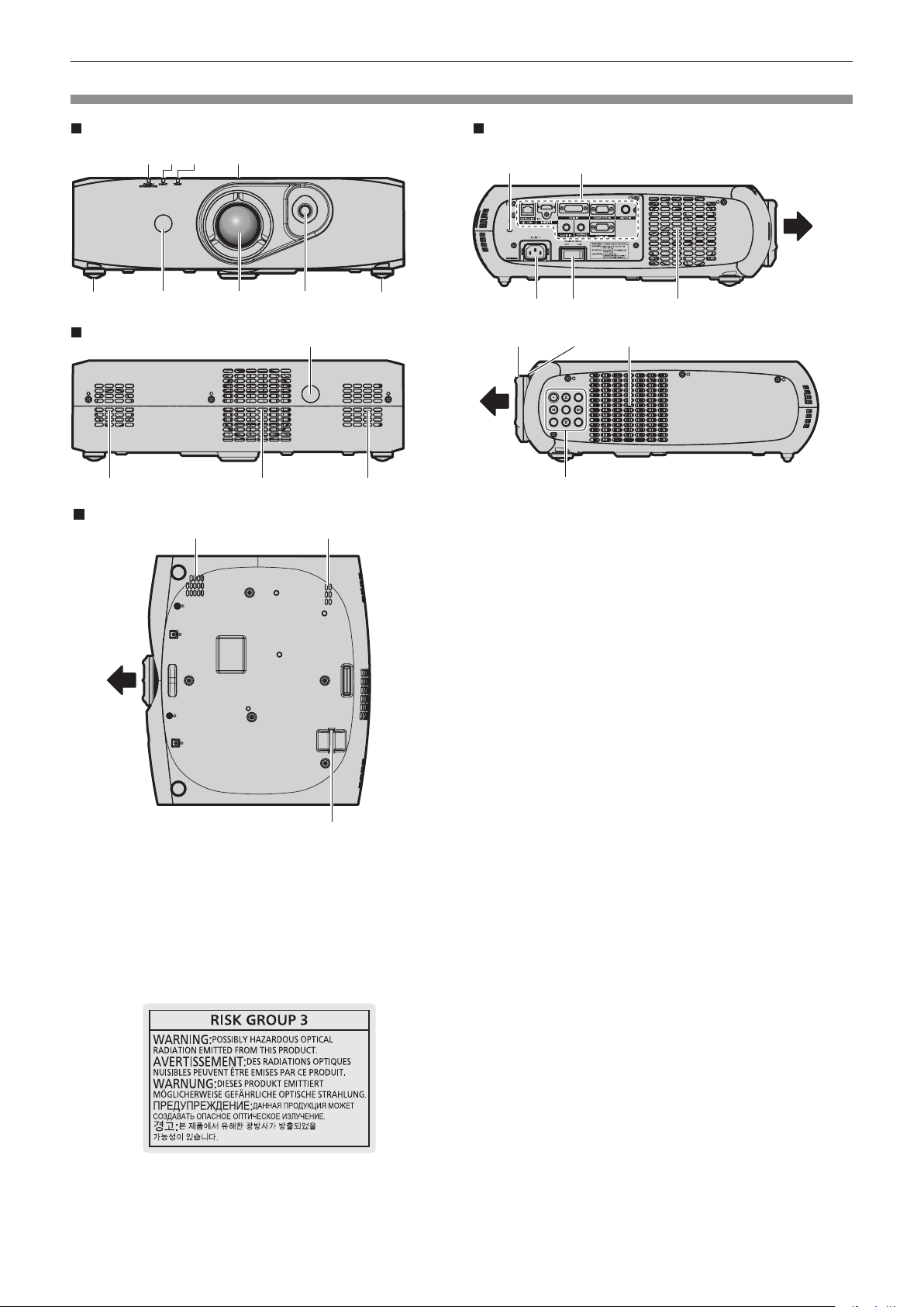
1 Power indicator <ON (G)/STANDBY (R)>
Displays the status of the power.
2 Light source indicator <LIGHT>
Displays the status of the light source.
3 Temperature indicator <TEMP>
Displays the internal temperature status.
4 RISK GROUP 3 label
The following label is attached to the top surface of the
projector.
)URQW
8 Lens shift lever
Adjusts the projection position.
9 Air intake port
10 Air exhaust port
11 Remote control signal receiver (rear)
12 Security slot
This security slot is compatible with the Kensington security
cables.
13 Connecting terminals (x page 22)
14 <AC IN> terminal
Connect the supplied power cord.
15 <MAIN POWER> switch
Turns on/off the main power.
16 Focus ring
Adjusts the focus.
17 Zoom ring
Adjusts the zoom.
18 Control panel (x page 22)
19 Burglar hook port
You can attach a commercial burglar prevention cable.
)URQW
5 Adjustable feet
Adjusts the projection angle.
6 Remote control signal receiver (front)
7 Projection lens
TQFX340
ENGLISH - 21
Page 22
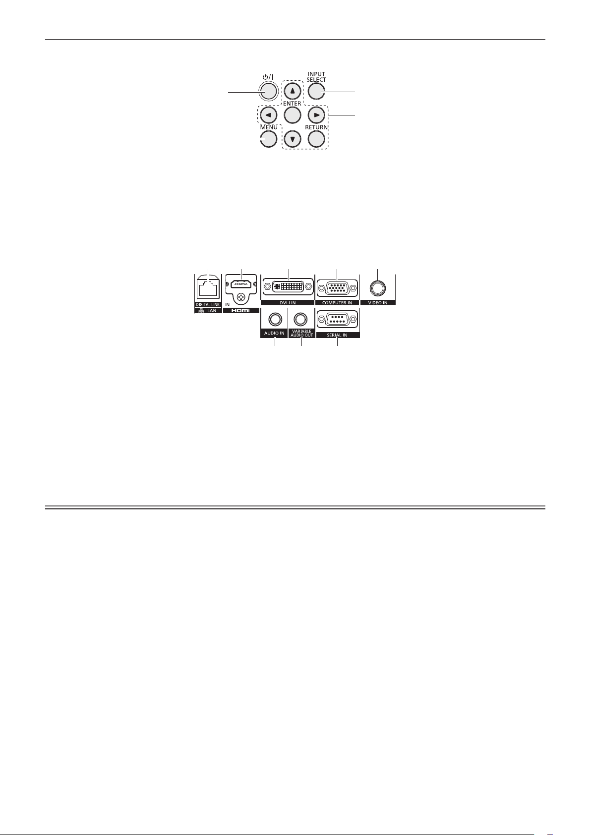
rControl panel
Chapter 1 Preparation — About your projector
1
2
1 Power <v/b> button
Sets the projector to the state where the projector is switched
off (standby mode) when the <MAIN POWER> switch on the
projector is set to <ON> and in projection mode. Also sets the
projector in projection mode when the power is switched off
(standby mode).
rConnecting terminals
1 2 3 4 5
1 <DIGITAL LINK/LAN> terminal
This is the LAN terminal to connect to the network. This is
also used when connecting an audio and video signal sending
device via the LAN terminal.
2 <HDMI IN> terminal
This is the terminal to input HDMI signals.
3 <DVI-I IN> terminal
This is the terminal to input DVI-D and DVI-A signals (RGB
signals or YC
4 <COMPUTER IN> terminal
This is the terminal to input RGB or YC
a computer.
Attention
BCR
/YPBPR).
/YPBPR signals from
BCR
3
4
2 <MENU> button
Displays the main menu.
3 <INPUT SELECT> button
Switches the input signal to project. (x page 39)
4
asqw
Used to navigate through the menu screen.
Also used to enter a [SECURITY] password or character input.
5 <VIDEO IN> terminal
This is the terminal to input video signals.
6 <AUDIO IN> terminal
This is the terminal to input audio signals.
7 <VARIABLE AUDIO OUT> terminal
This is the terminal to output audio signals input to the projector.
8 <SERIAL IN> terminal
This is the RS-232C compatible terminal to externally control
the projector by connecting a computer.
buttons/<RETURN> button/<ENTER> button
876
fWhen a LAN cable is directly connected to the projector, the network connection must be made indoors.
22 - ENGLISH
Page 23

Chapter 1 Preparation — Using the remote control
Using the remote control
Inserting and removing the batteries
(ii)
(i)
Fig. 1 Fig. 2
Open the cover. (Fig. 1)
1)
Insert the batteries and close the cover (insert the m side first). (Fig. 2)
2)
fWhen removing the batteries, perform the steps in reverse order.
Setting the remote control ID numbers
When you use the system with multiple projectors, you can operate all the projectors simultaneously or each projector individually using single
remote control, if a unique ID number is assigned to each projector.
After setting the ID number of the projector, set same ID number on the remote control.
The factory default ID number of the projector is set to [ALL]. When using a single projector, press the <ID ALL> button on the
remote control. Also, you can control a projector if you press the <ID ALL> button on the remote control even if you do not know the
projector ID.
How to set
Press the <ID SET> button on the remote control.
1)
Within five seconds, press the one-digit ID number set on the projector using the number (<1> - <6>)
2)
buttons.
fIf you press the <ID ALL> button, you can control the projectors regardless of the ID number setting of the projector.
Attention
fSince the ID number of the remote control can be set without the projector, do not press the <ID SET> button carelessly. If the <ID SET>
button is pressed and no number (<1> - <6>) buttons are pressed within ve seconds, the ID number returns to its original value before the
<ID SET> button was pressed.
fThe ID number set on the remote control will be stored unless it is set again. However, it will be erased if the remote control is left with dead
batteries. Set the same ID number again when the batteries are replaced.
Note
fSet the ID number of the projector from the [PROJECTOR SETUP] menu → [PROJECTOR ID] (x page 70).
ENGLISH - 23
Page 24

Chapter 2
This chapter describes things you need to do before using the projector such as the setup and connections.
Getting Started
24 - ENGLISH
Page 25
Chapter 2 Getting Started — Setting up
Setting up
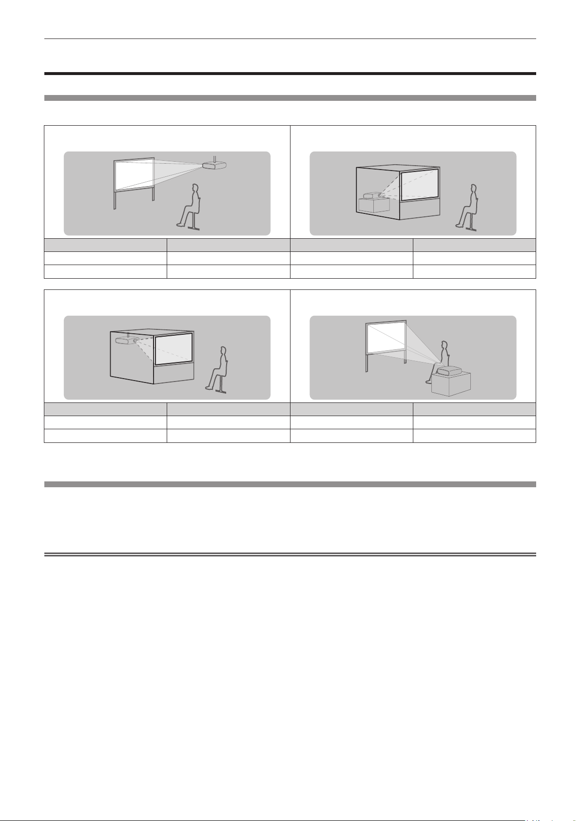
Projection method
You can use the projector with any of the following four projection methods. Select the appropriate method depending on the environment.
Mounting on the ceiling and projecting forward Setting on a desk/oor and projecting from rear
(Using the translucent screen)
Menu item
[PROJECTION METHOD] [FRONT/CEILING] [PROJECTION METHOD] [REAR/FLOOR]
[COOLING CONDITION] [CEILING SETTING] [COOLING CONDITION] [FLOOR SETTING]
Mounting on the ceiling and projecting from rear
(Using the translucent screen)
Menu item
[PROJECTION METHOD] [REAR/CEILING] [PROJECTION METHOD] [FRONT/FLOOR]
[COOLING CONDITION] [CEILING SETTING] [COOLING CONDITION] [FLOOR SETTING]
*1 For menu item details, refer to the [PROJECTOR SETUP] menu → [PROJECTION METHOD] (x page 70) and [COOLING CONDITION]
(x page 71).
*1
*1
Method Menu item
Setting on a desk/oor and projecting forward
Method Menu item
*1
*1
Method
Method
Parts for ceiling mount (optional)
You can install the projector on the ceiling using the optional ceiling mount bracket (Model No.: ET-PKR100H (for high ceilings), or
ET-PKR100S (for low ceilings).
fUse only the ceiling mount brackets specied for this projector.
fRefer to the installation manual for the ceiling mount bracket when installing and setting up the bracket and the projector.
Attention
fTo ensure projector performance and security, installation of the ceiling mount bracket must be carried out by your dealer or a qualied
technician.
ENGLISH - 25
Page 26
Chapter 2 Getting Started — Setting up
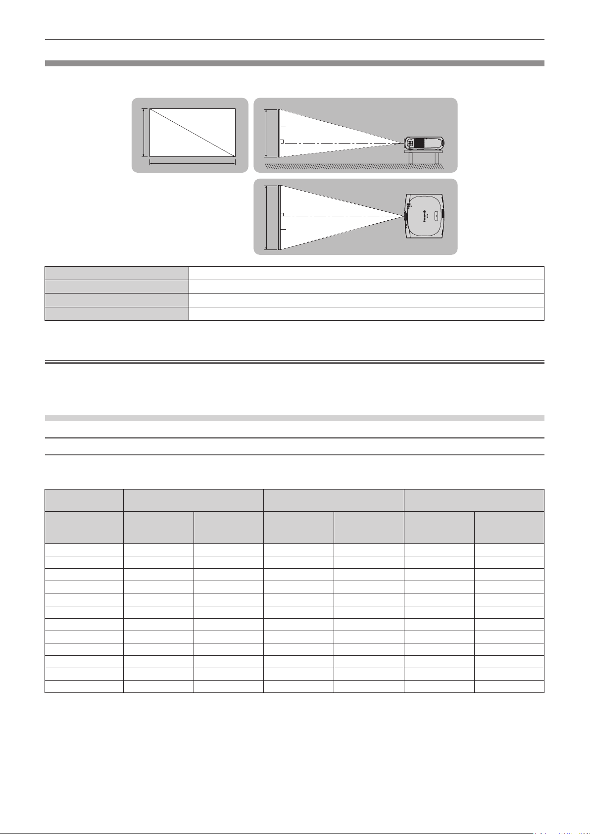
Screen size and throw distance
Refer to the following gures and table describing projection distances to install the projector. Image size and image position can be adjusted
in accordance with the screen size and screen position.
3URMHFWLRQVFUHHQ
6+
L (LW/LT)
*1 LW: Minimum projection distance
LT: Maximum projection distance
*1
SH Image height (m)
SW Image width (m)
SD Image diagonal size (m)
6'
6:
Projection distance (m)
6FUHHQ
//:/7
//:/7
6: 6+
6FUHHQ
Attention
fBefore setting up, read “Precautions for use” (x page 14).
fDo not use the projector and the high-powered laser equipment in the same room.
fHitting of a laser beam on to the lens can damage the DLP chips.
Projection distance
For PT-RZ370EA
(The dimensions of the following table contain a slight error.)
Projection screen
size
Min. projection
Diagonal (SD)
1.02 (40") 1.55 (5.10') 3.16 (10.39') 1.26 (4.13') 2.58 (8.47') 1.36 (4.48') 2.79 (9.16')
1.27 (50") 1.95 (6.42') 3.97 (13.02') 1.59 (5.21') 3.23 (10.62') 1.72 (5.65') 3.50 (11.49')
1.52 (60") 2.36 (7.74') 4.77 (15.66') 1.91 (6.29') 3.89 (12.77') 2.07 (6.82') 4.21 (13.81')
1.78 (70") 2.76 (9.06') 5.57 (18.29') 2.24 (7.37') 4.54 (14.92') 2.43 (7.99') 4.92 (16.14')
2.03 (80") 3.16 (10.39') 6.37 (20.92') 2.57 (8.45') 5.20 (17.07') 2.79 (9.15') 5.62 (18.46')
2.29 (90") 3.56 (11.71') 7.18 (23.55') 2.90 (9.53') 5.85 (19.22') 3.14 (10.32') 6.33 (20.79')
2.54 (100") 3.97 (13.03') 7.98 (26.19') 3.23 (10.61') 6.51 (21.37') 3.50 (11.49') 7.04 (23.11')
3.05 (120") 4.77 (15.67') 9.58 (31.45') 3.89 (12.77') 7.82 (25.67') 4.21 (13.82') 8.46 (27.76')
3.81 (150") 5.98 (19.63') 11.99 (39.35') 4.88 (16.01') 9.79 (32.13') 5.28 (17.32') 10.59 (34.74')
5.08 (200") 7.99 (26.24') 16.00 (52.51') 6.52 (21.41') 13.07 (42.88') 7.05 (23.16') 14.13 (46.37')
6.35 (250") 10.01 (32.85') 20.01 (65.67') 8.17 (26.80') 16.34 (53.63') 8.83 (28.99') 17.67 (57.99')
7.62 (300") 12.02 (39.45') 24.03 (78.83') 9.81 (32.20') 19.62 (64.39') 10.61 (34.83') 21.22 (69.62')
4:3 aspect ratio 16:9 aspect ratio 16:10 aspect ratio
distance
(LW)
Max. projection
distance
(LT)
Min. projection
distance
(LW)
Max. projection
distance
(LT)
Min. projection
distance
(LW)
Max. projection
(Unit: m)
distance
(LT)
26 - ENGLISH
Page 27
Chapter 2 Getting Started — Setting up
For PT-RW330EA
(The dimensions of the following table contain a slight error.)
(Unit: m)
Projection screen
size
Min. projection
Diagonal (SD)
1.02 (40") 1.46 (4.81') 2.99 (9.81') 1.32 (4.53') 2.71 (8.90') 1.29 (4.23') 2.63 (8.65')
1.27 (50") 1.84 (6.06') 3.75 (12.30') 1.67 (5.49') 3.40 (11.15') 1.62 (5.33') 3.30 (10.85')
1.52 (60") 2.22 (7.31') 4.50 (14.79') 2.01 (6.62') 4.08 (13.41') 1.96 (6.43') 3.97 (13.05')
1.78 (70") 2.60 (8.56') 5.26 (17.27') 2.36 (7.75') 4.77 (15.67') 2.29 (7.54') 4.64 (15.24')
2.03 (80") 2.99 (9.81') 6.02 (19.76') 2.71 (8.89') 5.46 (17.93') 2.63 (8.64') 5.31 (17.44')
2.29 (90") 3.37 (11.06') 6.78 (22.25') 3.05 (10.02') 6.15 (20.19') 2.97 (9.74') 5.98 (19.64')
2.54 (100") 3.75 (12.30') 7.54 (24.74') 3.40 (11.15') 6.84 (22.45') 3.30 (10.85') 6.65 (21.83')
3.05 (120") 4.51 (14.80') 9.05 (29.71') 4.09 (13.42') 8.21 (26.96') 3.98 (13.05') 7.99 (26.23')
3.81 (150") 5.65 (18.55') 11.33 (37.18') 5.12 (16.82') 10.28 (33.74') 4.98 (16.36') 10.00 (32.82')
5.08 (200") 7.55 (24.79') 15.12 (49.61') 6.85 (22.49') 13.72 (45.03') 6.66 (21.88') 13.35 (43.81')
6.35 (250") 9.46 (31.03') 18.91 (62.05') 8.58 (28.16') 17.16 (56.32') 8.35 (27.39') 16.70 (54.80')
7.62 (300") 11.36 (37.28') 22.70 (74.49') 10.31 (33.83') 20.61 (67.61') 10.03 (32.91') 20.05 (65.78')
4:3 aspect ratio 16:9 aspect ratio 16:10 aspect ratio
distance
(LW)
Max. projection
distance
(LT)
Min. projection
distance
(LW)
Max. projection
distance
(LT)
Min. projection
distance
(LW)
Max. projection
distance
(LT)
Projection distance formulas
To use a screen size not listed in this manual, check the screen size SD (m) and use the following formula to calculate projection distance.
The unit of the formula is m. (The values of the following calculation results contain slight error.)
For PT-RZ370EA
4:3 aspect ratio 16:9 aspect ratio 16:10 aspect ratio
Screen size Height (SH) = SD x 0.6 = SD x 0.490 = SD x 0.530
Screen size Width (SW) = SD x 0.8 = SD x 0.872 = SD x 0.848
Min. projection distance (LW) = 1.5854 x SD - 0.0544 = 1.2955 x SD - 0.0544 = 1.4004 x SD - 0.0544
Max. projection distance (LT) = 3.1589 x SD - 0.0408 = 2.5812 x SD - 0.0408 = 2.7904 x SD - 0.0408
For PT-RW330EA
4:3 aspect ratio 16:9 aspect ratio 16:10 aspect ratio
Screen size Height (SH) = SD x 0.6 = SD x 0.490 = SD x 0.530
Screen size Width (SW) = SD x 0.8 = SD x 0.872 = SD x 0.848
Min. projection distance (LW) = 1.4984 x SD - 0.0542 = 1.3604 x SD - 0.0542 = 1.3236 x SD - 0.0542
Max. projection distance (LT) = 2.9851 x SD - 0.0407 = 2.7102 x SD - 0.0407 = 2.6369 x SD - 0.0407
Adjusting adjustable feet
Install the projector on a at surface so that the front of the projector is parallel to the screen surface and the projection screen is rectangular.
If the screen is tilted downward, the projection screen can be adjusted to be rectangular by adjusting the adjustable feet. The adjustable feet
can also be used to adjust the projector to be level when it is tilted in a horizontal direction.
Extend the adjustable feet by rotating in the direction shown in the gure and retract by rotating in the opposite direction.
$GMXVWDEOHDPRXQW
)URQWDGMXVWDEOHIHHW$SSUR[PP
Attention
fWhen adjusting the adjustable feet when the light source is on, make sure that your hands do not block the intake and exhaust. (x page 21)
fWhen there is trapezoidal distortion, execute the [POSITION] menu → [KEYSTONE] (x page 55).
ENGLISH - 27
Page 28
Chapter 2 Getting Started — Connecting
Connecting
Before connecting
fBefore connecting, carefully read the operating instructions for the external device to be connected.
fTurn off the power of all devices before connecting cables.
fTake note of the following points before connecting the cables. Failure to do so may result in malfunctions.
gWhen connecting a cable to a device connected to the projector or the projector itself, touch any nearby metallic objects to eliminate static
electricity from your body before performing work.
gDo not use unnecessarily long cables to connect to a device connected to the projector or to the projector body. The longer the cable, the
more it is susceptible to noise. Since using a cable while it is wound makes it act like an antenna, it is more susceptible to noise.
gWhen connecting cables, connect GND rst, then insert the connecting terminal of the connecting device in a straight manner.
fAcquire any connection cable necessary to connect the external device to the system that is either not supplied with the device or not
available as an option.
fVideo signals containing too much jitter may cause the images on the screen to randomly wobble or wafture. In this case, a time base
corrector (TBC) must be connected.
fThe projector accepts video signals, analog RGB signals (synchronous signals are TTL level), and digital signals.
fSome computer models are not compatible with the projector.
fUse a cable compensator when you connect devices to the projector using long cables. Otherwise the image may not display properly.
fRefer to “List of compatible signals” (x page 122) for the types of video signals that can be used with the projector.
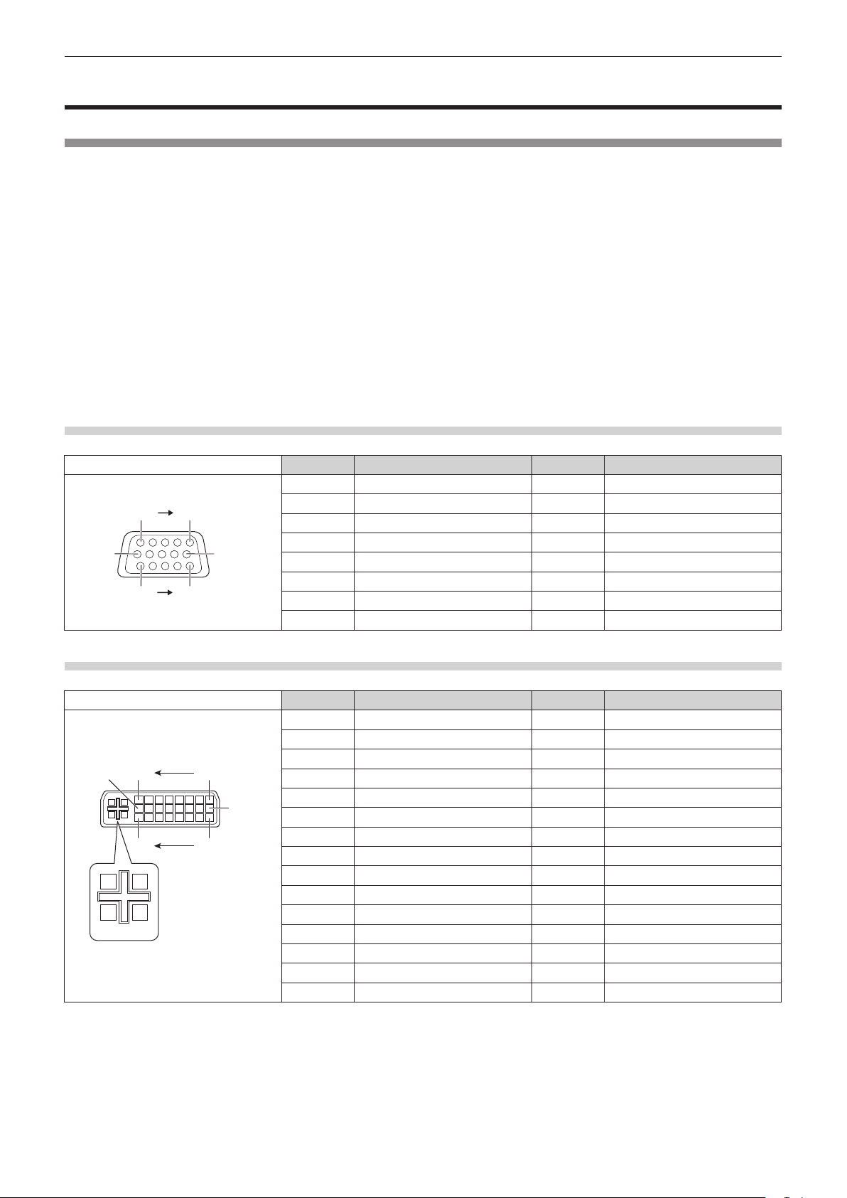
<COMPUTER IN> terminal pin assignments and signal names
Outside view Pin No. Signal name Pin No. Signal name
(6)
(11) (15)
(1) (5)
(10)
(1) R/P
(2) G/Y (10) GND
(3) B/P
(4) ― (12) DDC data
(5) GND (13) SYNC/HD
(6) GND (14) VD
(7) GND (15) DDC clock
(8) GND
R
B
<DVI-I IN> terminal pin assignments and signal names
Outside view Pin No. Signal name Pin No. Signal name
(1) T.M.D.S data 2
(2) T.M.D.S data 2+ (17) T.M.D.S data 0
(16)
C1C3C2
C5
(17)(24)
(9)
(1)(8)
C4
(3) T.M.D.S data 2/4 shield (18) T.M.D.S data 0+
(4) ― (19) T.M.D.S data 0/5 shield
(5) ― (20) ―
(6) DDC clock (21) ―
(7) DDC data (22) T.M.D.S clock shield
(8) Analog VD (23) T.M.D.S clock+
(9) T.M.D.S data 1
(10) T.M.D.S data 1+ C1 Analog R/P
(11) T.M.D.S data 1/3 shield C2 Analog G/G SYNC/Y
(12) ― C3 Analog B/P
(13) ― C4 Analog HD/SYNC
(14) +5 V C5 Analog GND
(15) GND
(9) ―
(11) GND
-
-
(16) Hot plug detection
-
(24) T.M.D.S clock
-
R
B
28 - ENGLISH
Page 29
Chapter 2 Getting Started — Connecting
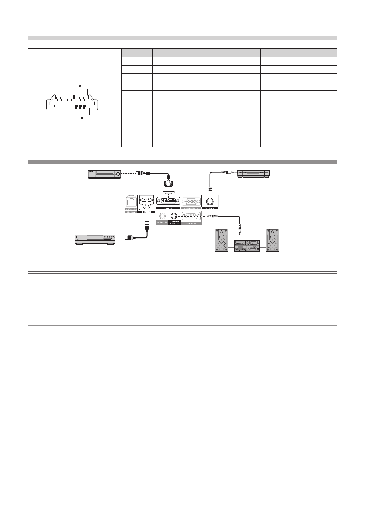
<HDMI IN> terminal pin assignments and signal names
Outside view Pin No. Signal name Pin No. Signal name
(1) T.M.D.S data 2+ (11) T.M.D.S clock shield
(2) T.M.D.S data 2 shield (12) T.M.D.S clock
Even-numbered pins (2) to (18)
(2) (18)
(1) (19)
Odd-numbered pins (1) to (19)
(3) T.M.D.S data 2
(4) T.M.D.S data 1+ (14) —
(5) T.M.D.S data 1 shield (15) SCL
(6) T.M.D.S data 1
(7) T.M.D.S data 0+ (17)
(8) T.M.D.S data 0 shield (18) +5 V
(9) T.M.D.S data 0
(10) T.M.D.S clock+
Connecting example: AV equipment
-
-
-
-
(13) CEC
(16) SDA
DDC/CEC
GND
(19) Hot plug detection
'9'SOD\HUZLWK+'0,
WHUPLQDO+'&3
%OXUD\GLVFSOD\HU
9&5ZLWKEXLOWLQ7%&
$XGLRGHYLFH
Attention
fAlways use one of the following when connecting a VCR.
gA VCR with built-in time base corrector (TBC)
gA time base corrector (TBC) between the projector and the VCR
fIf nonstandard burst signals are connected, the image may be distorted. In such case, connect the time base corrector (TBC) between the
projector.
fUse a commercial HDMI/DVI conversion cable with a ferrite core.
Note
fThe <DVI-I IN> terminal can be connected to HDMI- or DVI-I-compliant devices. However, images may not appear or may not be displayed
properly on some devices. (x page 63)
fFor an HDMI cable, use an HDMI High Speed cable that conforms to HDMI standards. If a cable that does not conform to HDMI standards
is used, images may be interrupted or not displayed, or the projector may not function properly.
fThe <HDMI IN> terminal of the projector can be connected to an external device with an DVI terminal by using an HDMI/DVI conversion
cable, but some devices may not project the image properly or function properly. (x page 64)
fWhen DVI-I is input, some external devices to be connected may require EDID to be set. (x page 63)
fThe projector does not support VIERA Link (HDMI).
fIf the [AUDIO IN SELECT] settings are incorrect, the projector may not output audio or otherwise function properly. (x page 79)
ENGLISH - 29
Page 30
Chapter 2 Getting Started — Connecting
&RPSXWHU
&RPSXWHU
&RPSXWHU
Connecting example: Computers
&RQWUROFRPSXWHU
&RPSXWHU
&RQWUROFRPSXWHU
Attention
fWhen connecting the projector to a computer or an external device, use the power cord supplied with each device and commercially
available shielded cables.
fUse a commercial DVI-D cable with a ferrite core.
Note
fFor an HDMI cable, use an HDMI High Speed cable that conforms to HDMI standards. If a cable that does not conform to HDMI standards
is used, images may be interrupted or not displayed, or the projector may not function properly.
fThe <HDMI IN> terminal of the projector can be connected to an external device with an DVI terminal by using an HDMI/DVI conversion
cable, but some devices may not project the image properly or otherwise function properly. (x page 64)
fThe <DVI-I IN> terminal (for digital input) supports single link only.
fFor signals that the projector can project, refer to “List of compatible signals” (x page 122).
fIf you operate the projector using the computer with the resume feature (last memory), you may have to reset the resume feature to operate
the projector.
fDuring DVI digital signal input, EDID settings may be necessary depending on the external devices to be connected. (x page 63)
fIf the [AUDIO IN SELECT] settings are incorrect, the projector may not output audio or otherwise function properly. (x page 79)
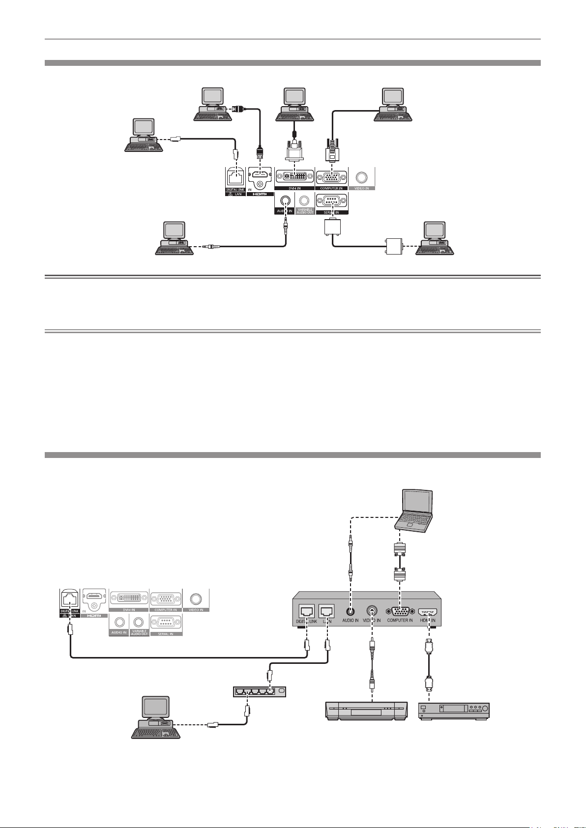
Connecting example: Twisted-pair-cable transmitter
Twisted-pair-cable transmitters such as the optional digital interface box (Model No.: ET-YFB100G) use twisted-pair-cables to transmit input
video, audio, Ethernet, and serial signals, and the projector can input those digital signals to the <DIGITAL LINK/LAN> terminal.
3URMHFWRUFRQQHFWLQJWHUPLQDOV
&RQWUROFRPSXWHU
([DPSOHRIWZLVWHGSDLUFDEOHWUDQVPLWWHU
+XE
9&5
&RPSXWHU
&RPSXWHUFDEOH
FRPPHUFLDOO\DYDLODEOH
+'0,FDEOH
FRPPHUFLDOO\DYDLODEOH
%OXUD\GLVFSOD\HU
30 - ENGLISH
Page 31

Chapter 2 Getting Started — Connecting
Attention
fAlways use one of the following when connecting a VCR.
gA VCR with built-in time base corrector (TBC)
gA time base corrector (TBC) between the projector and the VCR
fIf nonstandard burst signals are connected, the image may be distorted. In such case, connect the time base corrector (TBC) between the
projector.
fUse a commercial HDMI/DVI conversion cable with a ferrite core.
fAsk a qualied technician or your dealer to install the cable wiring for a twisted-pair-cable transmitter and the projector connection. Image
and sound may be disrupted if cable transmission characteristics can not be obtained due to inadequate installation.
fFor the LAN cable between a twisted-pair-cable transmitter and the projector, use a cable that meets the following criteria:
gCompatible with CAT5e or higher
gShielded type (including connectors)
gStraight-through
gSingle wire
fWhen laying cables between a twisted-pair-cable transmitter and the projector, check that cable characteristics are compatible with CAT5e
or higher using tools such as a cable tester or cable analyzer.
When using a relay connector midway, include it in the measurement.
fDo not use a hub between a twisted-pair-cable transmitter and the projector.
fWhen connecting to the projector using a twisted-pair-cable transmitter (receiver) of other company, do not place another twisted-pair-
cable transmitter in between the twisted-pair-cable transmitter of other company and the projector. This may cause sound and image to be
disrupted.
fDo not pull cables forcefully. Also, do not bend or fold cables unnecessarily.
fTo reduce noise, stretch out the cables between the twisted-pair-cable transmitter and the projector without any loops as much as possible
before setting them up and using them.
fLay the cables between a twisted-pair cable transmitter and the projector away from other cables, particularly power cables.
fWhen installing multiple cables, run them side by side along the shortest distance possible without bundling them together.
fAfter laying the cables, conrm that the [SIGNAL QUALITY] value is displayed in green to indicate normal quality using the [NETWORK]
menu → [DIGITAL LINK STATUS]. (x page 90)
Note
fFor an HDMI cable, use an HDMI High Speed cable that conforms to HDMI standards. If a cable that does not conform to HDMI standards
is used, images may be interrupted or may not be displayed.
fThe projector does not support VIERA Link (HDMI).
fThe maximum transmission distance between the twisted-pair-cable transmitter and the projector is 100 m (328'1"). If this distance is
exceeded, image and sound may be disrupted and may cause a malfunction in LAN communication. Please note that we do not support the
use of the projector outside the maximum transmission distance.
fFor twisted-pair-cable transmitter of other manufacturers of which the operation has been veried with the DIGITAL LINK compatible
projector, refer to Panasonic website (http://panasonic.net/avc/projector/). Note that the verication for devices of other manufacturers
has been made for the items set by Panasonic Corporation, and not all the operations have been veried. For operation or performance
problems caused by the devices of other manufacturers, contact the respective manufacturers.
ENGLISH - 31
Page 32

Chapter 3
This chapter describes basic operations to start with.
Basic Operations
32 - ENGLISH
Page 33

Chapter 3 Basic Operations — Switching on/off the projector
3RZHULQGLFDWRU21*67$1'%<5!
Switching on/off the projector
Connecting the power cord
Make sure that the supplied power cord is securely xed to the projector body to prevent it from being removed easily.
Conrm that the <MAIN POWER> switch is on the <OFF> side before connecting the power cord.
For details of power cord handling, refer to “Read this rst!” (x page 2).
Attaching the power cord
Check the shapes of the <AC IN> terminal on the side of the projector body and the power cord
1)
connector and insert the plug completely in the correct direction until you hear the hooks click in
place.
Removing the power cord
Confirm that the <MAIN POWER> switch of the main side is on the <OFF> side, and remove the power
1)
plug from the outlet.
Remove the power cord connector from the <AC IN> terminal of the projector body while pressing the
2)
side tabs.
Power indicator
Displays the status of the power. Check the <ON (G)/STANDBY (R)> status of the power indicator before operating the projector.
ENGLISH - 33
Page 34

Chapter 3 Basic Operations — Switching on/off the projector
Indicator status Status
Off The main power is switched off.
The power is switched off (in standby mode). [STANDBY MODE] is set to [NORMAL].
Flashing
Red
Lit
Green Lit Projecting.
Projection will start when the power <v/b> button is pressed.
fThe projector may not operate when the temperature indicator <TEMP> is ashing.
(x page 110)
The power is switched off (in standby mode). [STANDBY MODE] is set to [ECO].
Projection will start when the power <v/b> button is pressed.
fThe projector may not operate when the temperature indicator <TEMP> is ashing.
(x page 110)
Note
fThe projector consumes power even in standby mode (the power indicator <ON (G)/STANDBY (R)> lights/ashes in red).
Refer to “Power consumption” (x page 124) for the power consumption.
fThe power indicator <ON (G)/STANDBY (R)> ashes in green if a remote control signal is received.
fThe power indicator <ON (G)/STANDBY (R)> ashes in green slowly when the projector is in AV mute mode.
Switching on the projector
3)
3)
1)
Connect the power plug to an outlet.
1)
f(AC 100 V - 240 V 50 Hz/60 Hz)
Press the <ON> side of the <MAIN POWER> switch to turn on the power.
2)
fThe power indicator <ON (G)/STANDBY (R)> lights/ashes in red, and the projector enters the standby mode.
Press the power <v/b> button.
3)
fThe power indicator <ON (G)/STANDBY (R)> lights in green and the image is soon projected on the screen.
2)
Note
fIf the projector is switched on at around 0 °C (32 °F), a warm-up period of approximately ve minutes may be necessary until an image is
displayed.
The temperature indicator <TEMP> lights during the warm-up period. When the warm-up is completed, the temperature indicator <TEMP>
turns off and the projection starts. Refer to “Managing the indicated problems” (x page 110) for the indicator status.
fIf the operating environment temperature is low and warm-up takes more than ve minutes, the projector will judge that a problem has
occurred and the power will automatically be set to standby mode. If this happens, increase the operating environment temperature to 0 °C
(32 °F) or higher, turn off the main power, and then turn on the power again.
fIf the [PROJECTOR SETUP] menu → [ECO MANAGEMENT] → [STANDBY MODE] (x page 72) is set to [ECO], there may be a delay in
displaying when the power is turned on compared to when the setting is [NORMAL].
fWhen the power is turned or an input signal is switched, you may here a high-frequency driving sound. This is not a malfunction.
fIf the [PROJECTOR SETUP] menu → [INITIAL STARTUP] (x page 75) is set to [LAST MEMORY] and the power is turned off by pressing
the <OFF> side of the <MAIN POWER> switch or by using the breaker directly while projecting at the last time of use, the power indicator
<ON (G)/STANDBY (R)> lights in green and projection starts after a while when the power is turned on by pressing the <ON> side of the
<MAIN POWER> switch with the power plug connected to the outlet, or when the breaker is turned on.
34 - ENGLISH
Page 35

Chapter 3 Basic Operations — Switching on/off the projector
Making adjustments and selections
It is recommended that images are projected continuously for at least 30 minutes before the focus is adjusted.
2)1)
3)
Set the initial settings. (x page 19)
1)
fThe initial setting screen is displayed when the projector is switched on for the rst time after purchase as well as when [ALL USER
DATA] (x page 82) in [INITIALIZE] is executed.
Press the input selection (<COMPUTER>, <DVI-I>, <VIDEO>, <DIGITAL LINK>, <HDMI>) buttons to
2)
select the input signal. (x page 39)
4)
2)
1)
Adjust the front, back and sideway tilt of the projector with the adjustable feet. (x page 27)
3)
If the input signal is an RGB input signal, press the <AUTO SETUP> button. (x page 39)
4)
Switching off the projector
3)
Press the power <v/b> button.
1)
fThe [POWER OFF(STANDBY)] conrmation screen is displayed.
Press qw to select [OK], and press the <ENTER> button.
2)
(Or press the power <v/b> button again.)
fProjection of the image stops.
4)
1) 2)
1)
2)
Wait for a few seconds until the power indicator <ON (G)/STANDBY (R)> of the projector body lights/
3)
flashes in red.
Press the <OFF> side of the <MAIN POWER> switch to turn off the power.
4)
Note
fThe projector consumes power if the main power of the projector is on, even when the power <v/b> button is pressed and the
power is switched off.
When the [STANDBY MODE] menu (x page 72) is set to [ECO], the power consumption during standby can be conserved.
fThe power can be turned off by pressing the <OFF> side of the <MAIN POWER> switch while projecting or by directly using the breaker
under conditions where the <MAIN POWER> switch of the projector cannot be switched off/on easily such as while mounting on the ceiling.
However, the settings or adjustments performed right before the power is turned off may not be reected.
ENGLISH - 35
Page 36

Chapter 3 Basic Operations — Projecting
=RRPULQJ
Projecting
Check the external device connections (x page 28) and the power cord connection (x page 33), and turn on the projector (x page 34)
to start projecting. Select the video for projection, and adjust appearance of the projected image.
Selecting the input signal
Select an input signal.
Press the input selection (<COMPUTER>, <DVI-I>, <VIDEO>, <DIGITAL LINK>, <HDMI>) buttons on the
1)
remote control or the <INPUT SELECT> button on the control panel.
fThe image of the signal being input in the selected terminal is projected.
Attention
fImages may not be projected properly depending on the external device, or the blu-ray disc or DVD disc, to be played back.
Set the [PICTURE] menu → [SYSTEM SELECTOR] (x page 51).
fConrm the aspect ratio of the projection screen and the image, and switch to an optimum aspect ratio from the [POSITION] menu →
[ASPECT] (x page 53).
Adjusting the image
/HQVVKLIWOHYHU
)RFXVULQJ
)LJ )LJ
Adjust the projection angle.
1)
fPlace the projector parallel to the screen and install on a at surface so that the projection screen is rectangular.
fIf the projector is tilted further downward than the screen, adjust the projection screen to be rectangular by extending the adjustable
feet.
fRefer to “Adjusting adjustable feet” (x page 27) for details.
Release the lens shift lever lock by turning it counter-clockwise.
2)
Adjust the lens shift. (Fig. 1)
3)
fAdjust the projection position using the lens shift lever.
fRefer to “Adjustment range by the lens position shift (optical shift)” (x page 37) for details.
Lock the lens shift lever by turning it clockwise.
4)
Adjust the zoom and focus. (Fig. 2)
5)
fAdjust by turning the zoom ring and focus ring.
Attention
fNote that your ngers may get caught between the lens and surrounding area when adjusting the zoom, depending on the position of the
hand holding the zoom ring.
Note
fIt is recommended that images are projected continuously for at least 30 minutes before the focus is adjusted.
fTurning the focus ring changes the projection screen size. Make ne adjustments again to the projection screen size by turning the zoom
ring.
fWhen there is trapezoidal distortion, execute the [POSITION] menu → [KEYSTONE] (x page 55).
36 - ENGLISH
Page 37

Chapter 3 Basic Operations — Projecting
3URMHFWLRQVFUHHQZLGWK+
3URMHFWLRQVFUHHQZLGWK+
Adjustment range by the lens position shift (optical shift)
Perform the lens position shift within the adjustment range.
The focus may change when the lens position is shifted out of the adjustment range. This is because the movement of the lens is restricted to
protect the optical parts. Projection position can be adjusted with the optical axis shift based on the standard projection position in the range
shown in the following gures.
+
9
PT-RZ370EA
3URMHFWLRQVFUHHQKHLJKW9
9
+
9
PT-RW330EA
3URMHFWLRQVFUHHQKHLJKW9
9
* The numerical values in the preceding diagrams represent a case in which the projector is set on a desk/oor.
+
6WDQGDUGSURMHFWLRQSRVLWLRQ
+
6WDQGDUGSURMHFWLRQSRVLWLRQ
Note
fSet up the projector in front of the screen and adjust the lens shift lever to the center to obtain the optimal screen.
ENGLISH - 37
Page 38

Chapter 3 Basic Operations — Operating with the remote control
Operating with the remote control
Using the AV mute function
If the projector is not used for a certain period of time during the meeting intermission, for example, it is possible to turn off the audio and video
temporarily.
button
Press the <AV MUTE> button.
1)
fThe audio and video disappears.
Press the <AV MUTE> button again.
2)
fThere is audio and video.
Note
fThe power indicator <ON (G)/STANDBY (R)> ashes slowly when the projector is in AV mute mode.
fThe projector has no built-in speakers. There is audio output from the external sound system connected to the <VARIABLE AUDIO OUT>
terminal.
Using the Freeze function
The projected image can be paused temporarily and the audio muted, regardless of the playback of the external equipment.
button
Press the <FREEZE> button.
1)
fThe video pauses and the audio is muted.
Press the <FREEZE> button again.
2)
fVideo playback resumes and audio is unmuted.
Note
f[FREEZE] is displayed on the screen when video is paused.
38 - ENGLISH
Page 39

Chapter 3 Basic Operations — Operating with the remote control
Switching the input
The input for projection can be switched.
button
Press the input selection (<COMPUTER>, <DVI-I>, <VIDEO>, <DIGITAL LINK>, <HDMI>) buttons.
1)
fThis operation can be also performed using the <INPUT SELECT> button on the control panel.
<COMPUTER> Switches to COMPUTER input.
<DVI-I> Switches to DVI-I input.
<VIDEO> Switches to VIDEO input.
<DIGITAL LINK> Switches to DIGITAL LINK input.
<HDMI> Switches to HDMI input.
Note
fWhen the optional digital interface box (Model No.: ET-YFB100G) is connected to the <DIGITAL LINK/LAN> terminal, the ET-YFB100G input
changes with each press of the <DIGITAL LINK> button.
For twisted-pair-cable transmitters of other companies, switch the input on the twisted-pair-cable transmitter after switching to DIGITAL LINK
input.
Using the Automatic setup function
The automatic setup function can be used to automatically adjust the resolution, clock phase, and image position when analog RGB signals
consisting of bitmap images such as computer signals are being input, or to automatically adjust the image position when DVI-D/HDMI signals
are input. Supplying images with bright white borders at the edges and high-contrast black and white characters is recommended when the
system is in automatic adjustment mode.
Avoid supplying images that include halftones or gradation, such as photographs and computer graphics.
button
Press the <AUTO SETUP> button.
1)
f[COMPLETE] is displayed when it has completed without any problem.
Note
fThe clock phase may shift even if it has completed without any incident. In this case, adjust with the [POSITION] menu → [CLOCK PHASE]
(x page 54).
fIf an image with blurred edges or a dark image is input, [INCOMPLETE] may appear or adjustment may not be performed properly even
when [COMPLETE] appears. In this case, adjust the settings in the [ADVANCED MENU] menu → [INPUT RESOLUTION] (x page 57),
[POSITION] → [CLOCK PHASE] (x page 54), [SHIFT] (x page 52).
fAdjust special signals according to the [DISPLAY OPTION] menu → [AUTO SETUP] (x page 62).
fAutomatic adjustment may not work depending on the model of the computer.
fAutomatic adjustment may not work for a synchronization signal of C-SY or SYNC ON GREEN.
fImages may be disrupted for a few seconds during automatic adjustment, but it is not a malfunction.
fAdjustment is required for each input signal.
fAutomatic adjustment can be canceled by pressing the <RETURN> button or the <MENU> button during the automatic adjustment
operation.
fIf the automatic setup function is performed while moving images are being input, the adjustment may not be performed properly even for
an RGB signal for which automatic setup can be used. [INCOMPLETE] may appear, or adjustment may not be nished properly even if
[COMPLETE] appears.
ENGLISH - 39
Page 40

Chapter 3 Basic Operations — Operating with the remote control
Using the Function button
Frequently used operations can be assigned to the buttons from <FUNC1> to <FUNC3> on the remote control to be used as simple shortcut
buttons.
buttons
Press the <FUNC1> to <FUNC3> buttons.
1)
When assigning operations to the buttons from <FUNC1> to <FUNC3>
Press the <MENU> on the control panel or the remote control to display the menu items (main menu,
1)
sub-menu, or details menu) you want to assign.
fRefer to “Navigating through the menu” (x page 42) for the operation of the on-screen menu.
Press and hold any buttons from <FUNC1> to <FUNC3> for three seconds or more.
2)
Note
fWhen settings are completed, F1, F2, or F3 is displayed on the left of the menu item (main menu, sub-menu, or details menu) assigned
when <FUNC1>, <FUNC2>, or <FUNC3> is set, respectively.
fTo clear the assigned functions, perform the [PROJECTOR SETUP] menu → [FUNCTION BUTTON] (x page 78).
Using the ECO management function
The setting screen related to the ECO management can be displayed.
button
Press the <ECO> button on the remote control.
1)
Note
fRefer to the [PROJECTOR SETUP] menu → [ECO MANAGEMENT] (x page 71) for details.
Adjusting the volume
The audio output volume can be adjusted.
button
Press the <VOLUME+>/<VOLUME-> button on the remote control.
1)
<VOLUME+> Increases the volume.
<VOLUME
40 - ENGLISH
-
> Decreases the volume.
Page 41

Chapter 4
This chapter describes the settings and adjustments you can make using the on-screen menu.
Settings
ENGLISH - 41
Page 42

Chapter 4 Settings — Menu navigation
Menu navigation
The on-screen menu (Menu) is used to perform various settings and adjustments of the projector.
Navigating through the menu
Operating procedure
button
Press the <MENU> button on the remote control or control panel.
1)
fThe [MAIN MENU] screen is displayed.
0$,10(18
3,&785(
326,7,21
$'9$1&('0(18
',63/$</$1*8$*(
',63/$<237,21
352-(&7256(783
7(673$77(51
6,*1$//,67
6(&85,7<
1(7:25.
',*,7$//,1.
0(186(/(&7
(17(5
68%0(18
Press as to select an item from the main menu.
2)
fThe selected item is highlighted in yellow.
0$,10(18
3,&785(
326,7,21
$'9$1&('0(18
',63/$</$1*8$*(
',63/$<237,21
352-(&7256(783
7(673$77(51
6,*1$//,67
6(&85,7<
1(7:25.
',*,7$//,1.
0(186(/(&7
(17(5
68%0(18
Press the <ENTER> button.
3)
fThe sub-menu items of the selected main menu are displayed.
326,7,21
6+,)7
$63(&7
=220
&/2&.3+$6(
.(<6721(
1250$/
0(186(/(&7
(17(5
68%0(18
Press as to select a sub-menu, and press qw or the <ENTER> button to change or adjust settings.
4)
fMenu items switch in order as follows each time you press qw.
A B C
fFor some items, press qw to display an individual adjustment screen with a bar scale as shown below.
&2175$67
$'-867
42 - ENGLISH
Page 43

Chapter 4 Settings — Menu navigation
&XUUHQWDGMXVWPHQWYDOXH
Note
fPressing the <RETURN> button or the <MENU> button when the menu screen is displayed returns to the previous menu.
fSome items may not be adjusted or used for certain signal formats to be input to the projector. The menu items that cannot be adjusted or
used are shown in gray characters, and they cannot be selected.
fSome items can be adjusted even if signals are not input.
fIndividual adjustment screen is cleared automatically if no operation is performed for approximately ve seconds.
fFor menu items, refer to “Main menu” (x page 43) and “Sub-menu” (x page 44).
fThe cursor color depends on the settings of the [OSD DESIGN] menu (x page 65). The selected item is displayed with the yellow cursor
by default.
Resetting adjustment values to the factory default
If the <DEFAULT> button on the remote control is pressed, the values adjusted in the menu items are restored to the factory default settings.
button
Press the <DEFAULT> button on the remote control.
1)
&2175$67
$'-867
Note
fYou cannot reset all the settings to the factory default at a time.
fTo reset all the settings adjusted in the sub-menu item to the factory default at a time, execute the [PROJECTOR SETUP] menu →
[INITIALIZE] (x page 82).
fSome items cannot be reset by pressing the <DEFAULT> button. Adjust each item manually.
fThe square mark under the bar scale in the individual adjustment screen indicates the factory default setting. The position of the square
mark varies by the selected input signals.
)DFWRU\GHIDXOWVHWWLQJ
Setting the on-screen display to show/hide
If you press the <MENU> button on the control panel or the remote control for at least three seconds, the on-screen display setup screen is
displayed and the on-screen display can be set to show/hide.
Note
fIf the [SECURITY] menu → [TEXT DISPLAY] is [ON], the on-screen setting screen cannot be displayed.
Main menu
The main menu consists of the following 11 items.
When a main menu item is selected, the screen changes to a sub-menu selection screen.
Main menu item Page
[PICTURE] 47
[POSITION] 52
[ADVANCED MENU] 56
[DISPLAY LANGUAGE] 59
[DISPLAY OPTION] 60
[PROJECTOR SETUP] 70
ENGLISH - 43
Page 44

Chapter 4 Settings — Menu navigation
Main menu item Page
[TEST PATTERN] 83
[SIGNAL LIST] 84
[SECURITY] 86
[NETWORK] 89
[DIGITAL LINK] 108
Sub-menu
The sub-menu of the selected main menu item is displayed, and you can set and adjust items in the sub-menu.
[PICTURE]
Sub-menu item Factory default Page
BPR
*1
*1
*1
*1
]
47
50
50
51
[PICTURE MODE] [GRAPHIC]
[CONTRAST] [0] 47
[BRIGHTNESS] [0] 48
[COLOR] [0] 48
[TINT] [0] 48
[COLOR TEMPERATURE] [DEFAULT] 48
[DAYLIGHT VIEW] [AUTO] 50
[SHARPNESS] [6]
[NOISE REDUCTION] [OFF]
[SYSTEM SELECTOR] [YP
*1 Depends on the signal input.
Note
fThe factory default settings may vary depending on the picture mode.
[POSITION]
Sub-menu item Factory default Page
[SHIFT] ― 52
[ASPECT] [NORMAL] 53
[ZOOM] ― 53
[CLOCK PHASE] [16]
[KEYSTONE] [0] 55
*1 Depends on the signal input.
*1
[ADVANCED MENU]
Sub-menu item Factory default Page
[DIGITAL CINEMA REALITY] [AUTO]
[BLANKING] ― 56
[INPUT RESOLUTION] ― 57
[CLAMP POSITION] [24]
[FRAME RESPONSE] [NORMAL] 58
[RASTER POSITION] ― 58
*1 Depends on the signal input.
*1
*1
54
56
57
44 - ENGLISH
Page 45

Chapter 4 Settings — Menu navigation
Note
fSub-menu items and factory default settings differ depending on the input terminal that is selected.
[DISPLAY LANGUAGE]
Details (x page 59)
[DISPLAY OPTION]
Sub-menu item Factory default Page
[COLOR MATCHING] [OFF] 60
[SCREEN SETTING]
[AUTO SIGNAL] [OFF] 62
[AUTO SETUP] ― 62
[COMPUTER IN] ― 62
[DVI-I IN] ― 63
[HDMI IN] ― 64
[DIGITAL LINK IN] ― 64
[ON-SCREEN DISPLAY] ― 64
[CLOSED CAPTION SETTING] ― 66
[BACK COLOR] [BLUE] 67
[STARTUP LOGO] [DEFAULT LOGO] 67
[SUB MEMORY LIST] ― 68
[FREEZE] ― 68
[AV MUTE] ― 69
*1 Only for PT-RW330EA.
*1
― 61
[PROJECTOR SETUP]
Sub-menu item Factory default Page
[PROJECTOR ID] [ALL] 70
[PROJECTION METHOD] [FRONT/FLOOR] 70
[COOLING CONDITION] [FLOOR SETTING] 71
[ECO MANAGEMENT] ― 71
[SCHEDULE] [OFF] 73
[INITIAL STARTUP] [LAST MEMORY] 75
[STARTUP INPUT SELECT] [LAST USED] 75
[DIGITAL LINK INPUT] ― 76
[RS-232C] ― 76
[FUNCTION BUTTON] ― 78
[AUDIO SETTING] ― 78
[STATUS] ― 80
[DATE AND TIME] ― 80
[SAVE ALL USER DATA] ― 81
[LOAD ALL USER DATA] ― 81
[INITIALIZE] ― 82
[SERVICE PASSWORD] ― 82
ENGLISH - 45
Page 46

Chapter 4 Settings — Menu navigation
[TEST PATTERN]
Details (x page 83)
[SIGNAL LIST]
Details (x page 84)
[SECURITY]
Sub-menu item Factory default Page
[SECURITY PASSWORD] [OFF] 86
[SECURITY PASSWORD CHANGE] ― 86
[TEXT DISPLAY] [OFF] 87
[TEXT CHANGE] ― 87
[MENU LOCK] [OFF] 87
[MENU LOCK PASSWORD] ― 87
[CONTROL DEVICE SETUP] ― 88
[NETWORK]
Sub-menu item Factory default Page
[DIGITAL LINK MODE] [AUTO] 89
[DIGITAL LINK SETUP] ― 89
[DIGITAL LINK STATUS] ― 90
[NETWORK SETUP] ― 91
[NETWORK CONTROL] ― 91
[NETWORK STATUS] ― 92
[DIGITAL LINK]
Details (x page 108)
Note
fSome items may not be adjusted or used for certain signal formats to be input to the projector.
fThe menu items that cannot be adjusted or used are shown in gray characters, and they cannot be selected.
fSub-menu items and factory default settings differ depending on the selected input terminal.
46 - ENGLISH
Page 47

Chapter 4 Settings — [PICTURE] menu
[PICTURE] menu
On the menu screen, select [PICTURE] from the main menu, and select the item from the
sub-menu.
Refer to “Navigating through the menu” (x page 42) for the operation of the menu screen.
fAfter selecting the item, press
[PICTURE MODE]
You can switch to the desired picture mode suitable for the image source and the environment in which the projector is used.
Press as to select [PICTURE MODE].
1)
Press qw to switch [PICTURE MODE].
2)
fThe items will switch each time you press the button.
asqw
to set.
[GRAPHIC] The image becomes suitable for input from to the personal computer.
[STANDARD] The image becomes suitable for moving images in general.
[CINEMA] The image becomes suitable for movie sources.
[NATURAL] The image is sRGB compliant.
[REC709]
[DICOM SIM.]
[DYNAMIC] The light output is maximized for use in bright areas.
*1 Use the factory default for the settings other than [PICTURE MODE].
*1
*1
The image is REC709 compliant.
The image becomes similar to that of DICOM Part 14 Grayscale Standard.
Note
fThe factory default picture mode is [GRAPHIC] for still image input signals and [STANDARD] for movie based input signals.
fDICOM is an abbreviation of “Digital Imaging and Communication in Medicine” and is a standard for medical imaging devices. Although the
DICOM name is used, the projector is not a medical device, and should not be used for purposes such as diagnosis of displayed images.
[CONTRAST]
You can adjust the contrast of the colors.
Press as to select [CONTRAST].
1)
Press qw or the <ENTER> button.
2)
fThe [CONTRAST] individual adjustment screen is displayed.
Press qw to adjust the level.
3)
Operation Adjustment Range
Press the w button. Brightens the screen and makes the color deeper.
Press the q button. Darkens the screen and makes the color lighter.
-
31 - 31
Attention
fAdjust [BRIGHTNESS] rst when you need to adjust the black level.
ENGLISH - 47
Page 48

Chapter 4 Settings — [PICTURE] menu
[BRIGHTNESS]
You can adjust the dark (black) part of the projected image.
Press as to select [BRIGHTNESS].
1)
Press qw or the <ENTER> button.
2)
fThe [BRIGHTNESS] individual adjustment screen is displayed.
Press qw to adjust the level.
3)
Operation Adjustment Range
Press the w button. Increases the brightness of the dark (black) parts of the screen.
Press the q button. Reduces the brightness of the dark (black) parts of the screen.
[COLOR]
You can adjust the color saturation of the projected image.
Press as to select [COLOR].
1)
Press qw or the <ENTER> button.
2)
fThe [COLOR] individual adjustment screen is displayed.
Press qw to adjust the level.
3)
-
31 - 31
Operation Adjustment Range
Press the w button. Deepens colors.
Press the q button. Weakens colors.
[TINT]
You can adjust the skin tone in the projected image.
Press as to select [TINT].
1)
Press qw or the <ENTER> button.
2)
fThe [TINT] individual adjustment screen is displayed.
Press qw to adjust the level.
3)
Operation Adjustment Range
Press the w button. Adjusts skin tone toward greenish color.
Press the q button. Adjusts skin tone toward reddish purple.
[COLOR TEMPERATURE]
You can switch the color temperature if the white areas of the projected image are bluish or reddish.
Adjusting with color temperature
-
31 - 31
-
31 - 31
Press as to select [COLOR TEMPERATURE].
1)
Press qw or the <ENTER> button.
2)
fThe [COLOR TEMPERATURE] individual adjustment screen is displayed.
Press qw to switch [COLOR TEMPERATURE].
3)
fThe items will switch each time you press the button.
[DEFAULT] Factory default setting.
[USER]
[MIDDLE]
[HIGH]
Adjusts white balance as desired. Refer to “Adjusting desired white balance” to be described later for
details.
Select so that images become natural.
48 - ENGLISH
Page 49

Chapter 4 Settings — [PICTURE] menu
Note
fWhen [PICTURE MODE] (x page 47) is set to [DYNAMIC], [COLOR TEMPERATURE] is xed to [USER]. (However, [WHITE BALANCE
HIGH] cannot be adjusted.)
fWhen [COLOR MATCHING] (x page 60) adjustment is set to other than [OFF], [COLOR TEMPERATURE] is xed to [USER].
Adjusting desired white balance
Press as to select [COLOR TEMPERATURE].
1)
Press qw or the <ENTER> button.
2)
fThe [COLOR TEMPERATURE] individual adjustment screen is displayed.
Press qw to select [USER].
3)
Press the <ENTER> button.
4)
fThe [COLOR TEMPERATURE] screen is displayed.
Press as to select [WHITE BALANCE].
5)
Press the <ENTER> button.
6)
fThe [WHITE BALANCE] screen is displayed.
Press as to select [WHITE BALANCE HIGH] or [WHITE BALANCE LOW].
7)
Press the <ENTER> button.
8)
fThe [WHITE BALANCE HIGH] screen or the [WHITE BALANCE LOW] screen is displayed.
Press as to select [RED], [GREEN], or [BLUE].
9)
Press qw to adjust the level.
10)
Item Operation Adjustment Range
[RED]
[GREEN]
[BLUE]
Press the w button. Deepens red.
Press the q button. Weakens red.
Press the w button. Deepens green.
Press the q button. Weakens green.
Press the w button. Deepens blue.
Press the q button. Weakens blue.
[WHITE BALANCE HIGH]: 0 - 255 (factory default is 255)
[WHITE BALANCE LOW]: -127 - 127 (factory default is 0)
Note
fAdjust [COLOR TEMPERATURE] correctly. All colors will not be displayed properly unless adequate adjustment is made. If the adjustment
does not look suitable, you can press the <DEFAULT> button on the remote control to return the setting for the selected item only to the
factory default setting.
fThe setting of [COLOR TEMPERATURE] is not reected in internal test patterns (x page 83). Make sure to set [COLOR TEMPERATURE]
while projecting input signal.
Changing the [USER] name
Press as to select [COLOR TEMPERATURE].
1)
Press qw or the <ENTER> button.
2)
fThe [COLOR TEMPERATURE] individual adjustment screen is displayed.
Press qw to select [USER].
3)
Press the <ENTER> button.
4)
fThe [COLOR TEMPERATURE] screen is displayed.
Press as to select [COLOR TEMPERATURE NAME CHANGE].
5)
Press the <ENTER> button.
6)
fThe [COLOR TEMPERATURE NAME CHANGE] screen is displayed.
Press asqw to select the text, and press the <ENTER> button to enter the text.
7)
ENGLISH - 49
Page 50

Chapter 4 Settings — [PICTURE] menu
Press asqw to select [OK], and press the <ENTER> button.
8)
fThe name set to color temperature is changed.
Note
fWhen a name is changed, display of the [USER] menu is also changed.
[DAYLIGHT VIEW]
You can correct the image to the optimal vividness even if it is projected under a bright light.
Press as to select [DAYLIGHT VIEW].
1)
Press qw or the <ENTER> button.
2)
fThe [DAYLIGHT VIEW] individual adjustment screen is displayed.
Press qw to switch [DAYLIGHT VIEW].
3)
fThe items will switch each time you press the button.
[AUTO] Corrects the image vividness automatically.
[OFF] No correction.
[1] Corrects the image to weaken vividness.
[2] Corrects the image to medium vividness.
[3] Corrects the image to high vividness.
Note
fIf [REAR/FLOOR] or [REAR/CEILING] is selected with the [PROJECTOR SETUP] menu → [PROJECTION METHOD], [AUTO] cannot be
set.
f[AUTO] mode may not operate properly if objects are placed on top of the projector.
fIf [PICTURE MODE] is [NATURAL], [REC709], or [DICOM SIM.], the factory default setting is [OFF].
[SHARPNESS]
You can adjust the sharpness of the projected image.
Press as to select [SHARPNESS].
1)
Press qw or the <ENTER> button.
2)
fThe [SHARPNESS] individual adjustment screen is displayed.
Press qw to adjust the level.
3)
Operation Adjustment Range
Press the w button. Contours become sharper.
Press the q button. Contours become softer.
0 - 15
Note
fIf you press w while the adjustment value is [15], the value will become [0]. If you press q while the adjustment value is [0], the value will
become [15].
[NOISE REDUCTION]
You can reduce noises when the input image is degraded and noise is occurring in the image signal.
Press as to select [NOISE REDUCTION].
1)
Press qw or the <ENTER> button.
2)
fThe [NOISE REDUCTION] individual adjustment screen is displayed.
Press qw to switch [NOISE REDUCTION].
3)
fThe items will switch each time you press the button.
[OFF] No correction.
[ON] Corrects the noise.
Attention
fSetting the projector may result in an image that appears different from the actual image. In such a case, set it to [OFF].
50 - ENGLISH
Page 51

Chapter 4 Settings — [PICTURE] menu
[SYSTEM SELECTOR]
The projector will automatically detect the input signal, but you can set the system method manually when an unstable signal is input. Set the
system method matching the input signal.
Press as to select [SYSTEM SELECTOR].
1)
Press the <ENTER> button.
2)
Press as to select a system format.
3)
fAvailable system formats vary depending on the input signal.
Terminal System format
Select [AUTO], [NTSC], [NTSC4.43], [PAL], [PAL-M], [PAL-N], [SECAM], or [PAL60].
<VIDEO IN> terminal
<COMPUTER IN> terminal,
<DVI-I IN> terminal
<DVI-I IN> terminal
<HDMI IN> terminal
*1 When [DVI-I IN] is set to [ANALOG].
*2 When [DVI-I IN] is set to [DIGITAL].
Press the <ENTER> button.
4)
Set it to [AUTO] normally. (The [AUTO] setting will automatically select [NTSC], [NTSC4.43], [PAL],
[PAL-M], [PAL-N], [SECAM], or [PAL60].)
Switch the setting to the signal method for the TV used.
480i, 576i, or 576p signal Select [RGB] or [YCBCR].
*1
*2
VGA60 or 480p signal Select [VGA60], [480p], or [480pRGB].
Other movie based signals Select [RGB] or [YP
480p or 576p signal Select [RGB], [YCBCR444], or [YCBCR422].
Other movie based signals Select [RGB], [YP
480p or 576p signal Select [AUTO], [RGB], [YC
Other movie based signals Select [AUTO], [RGB], [YP
].
BPR
444], or [YPBPR422].
BPR
444], or [YCBCR422].
BCR
444], or [YPBPR422].
BPR
Note
fRefer to “List of compatible signals” (x page 122) for compatible signals.
fThis may not function properly for some external devices that are connected.
sRGB-compliant video
sRGB is an international standard (IEC61966-2-1) for color reproduction dened by IEC (International Electrotechnical Commission).
Set the projector using the following procedures for more accurate color reproduction that complies with sRGB.
Set [COLOR MATCHING] adjustments to [OFF].
1)
fRefer to [COLOR MATCHING] (x page 60).
Display the [PICTURE] menu.
2)
fRefer to “[PICTURE] menu” (x page 47).
Press as to select [PICTURE MODE].
3)
Press qw to set [NATURAL].
4)
Press as to select [COLOR].
5)
Press the <DEFAULT> button on the remote control to set factory default settings.
6)
Follow Steps 5) to 6) to set factory default settings for [TINT] and [COLOR TEMPERATURE].
7)
Note
fsRGB is available for RGB signal input only.
ENGLISH - 51
Page 52

Chapter 4 Settings — [POSITION] menu
[POSITION] menu
On the menu screen, select [POSITION] from the main menu, and select the item from the
sub-menu.
Refer to “Navigating through the menu” (x page 42) for the operation of the menu screen.
fAfter selecting the item, press
Note
fWhen the input is set to DIGITAL LINK, only [KEYSTONE] can be set. When the optional digital interface box (ET-YFB100G) is connected to
the projector, adjust the shift, aspect, and clock phase from the menu of ET-YFB100G.
[SHIFT]
You can move the image position vertically or horizontally if the image position projected on the screen is shifted even when the relative
position of the projector and the screen is installed correctly.
asqw
to set.
Press as to select [SHIFT].
1)
Press the <ENTER> button.
2)
fThe [SHIFT] screen is displayed.
Press asqw to adjust the position.
3)
Orientation Operation Adjustment
Press the a button. The image position moves up.
Vertical (up and down)
adjustment
Press the s button. The image position moves down.
Press the w button. The image position moves to the right.
Horizontal (right and left)
adjustment
52 - ENGLISH
Press the q button. The image position moves to the left.
Page 53

Chapter 4 Settings — [POSITION] menu
[ASPECT]
You can switch the aspect ratio of the image.
The aspect ratio is switched within the screen range selected in [SCREEN SETTING]. Set [SCREEN SETTING] rst. (x page 61)
[SCREEN SETTING] is available only on PT-RW330EA.
Press as to select [ASPECT].
1)
Press qw or the <ENTER> button.
2)
fThe [ASPECT] individual adjustment screen is displayed.
Press qw to switch [ASPECT].
3)
fThe items will switch each time you press the button.
[NORMAL] Display images without changing the aspect ratio of the input signals.
[NATIVE] Display images without changing the resolution of the input signals.
[WIDE]
[4:3]
[H FIT]
[V FIT]
[FULL]
*1 Standard signals are input signals with an aspect ratio of 4:3 or 5:4.
*2 Wide-screen signals are input signals with an aspect ratio of 16:10, 16:9, 15:9 or 15:10.
*3 For PT-RZ370EA, the [SCREEN FORMAT] setting is not available. The screen aspect ratio of PT-RZ370EA is 16:9.
Display images with the aspect ratio converted to 16:9 when standard signals are input
images without changing the aspect ratio when wide-screen signals are input*2.
Display images without changing the aspect ratio when standard signals are input
without changing the aspect ratio so that the images will t in the 4:3 screen when wide-screen
signals are input*2.
Display images using the entire width of the screen. When signals have the aspect ratio vertically
longer than the aspect ratio of the screen selected in [SCREEN FORMAT]
with the top and bottom parts cut off.
Display images using the entire height of the screen range selected in [SCREEN FORMAT]
signals have the aspect ratio horizontally longer than the aspect ratio of the screen selected in
[SCREEN FORMAT]*3, the images are displayed with the right and left parts cut off.
Display images in the entire screen range selected in [SCREEN FORMAT]
the input signals differs from that of the screen range, the images are displayed with the aspect ratio
converted to that of the screen selected in [SCREEN FORMAT]*3.
Note
*3
, the images are displayed
*3
. When the aspect ratio of
*1
*1
. Display images
. Display
*3
. When
fIf an aspect ratio different from the aspect ratio for the input signals is selected, the images will appear to be different from the originals. Be
careful of this when selecting the aspect ratio.
fIf using the projector in places such as cafes or hotels to display programs for a commercial purpose or for public presentation, note that
adjusting the aspect ratio or using the zoom function to change the screen images may be an infringement of the rights of the original
copyright owner for that program under copyright protection laws. Take care when using a function of the projector such as the aspect ratio
adjustment and zoom function.
fIf conventional (normal) 4:3 images which are not wide-screen images are displayed on a wide screen, the edges of the images may not
be visible or they may become distorted. Such images should be viewed as with an aspect ratio of 4:3 in the original format intended by the
creator of the images.
[ZOOM]
You can adjust the size of the screen size.
When [ASPECT] is set to other than [NORMAL] and [NATIVE]
Press as to select [ZOOM].
1)
Press the <ENTER> button.
2)
fThe [ZOOM] screen is displayed.
Press as to select [INTERLOCKED].
3)
Press qw to switch [INTERLOCKED].
4)
[OFF] Set the [VERTICAL] and [HORIZONTAL] zoom ratio.
[ON] Use [BOTH] to set zoom ratio. Horizontal and vertical can be expanded by units of 1.0 time.
Press as to select [VERTICAL] or [HORIZONTAL].
5)
fIf [ON] is selected, select [BOTH].
Press qw to adjust.
6)
ENGLISH - 53
Page 54

Chapter 4 Settings — [POSITION] menu
Note
fWhen [ASPECT] is set to [NATIVE], [ZOOM] cannot be adjusted.
When [ASPECT] is set to [NORMAL]
Press as to select [ZOOM].
1)
Press the <ENTER> button.
2)
fThe [ZOOM] screen is displayed.
Press as to select [MODE].
3)
Press qw to switch [MODE].
4)
[INTERNAL] Enlarges the size within the aspect range set with [SCREEN FORMAT].
[FULL] Enlarges the size to the entire display area set with [SCREEN FORMAT].
Press as to select [INTERLOCKED].
5)
Press qw to switch [INTERLOCKED].
6)
[OFF] Set the [VERTICAL] and [HORIZONTAL] zoom ratio.
[ON] Use [BOTH] to set zoom ratio. Horizontal and vertical can be expanded by units of 1.0 time.
Press as to select [VERTICAL] or [HORIZONTAL].
7)
fIf [ON] is selected, select [BOTH].
Press qw to adjust.
8)
Note
fWhen [ASPECT] is set to other than [NORMAL], [MODE] is not displayed.
[CLOCK PHASE]
You can adjust to achieve an optimal image when there is a ickering image or smeared outlines.
Press as to select [CLOCK PHASE].
1)
Press qw or the <ENTER> button.
2)
fThe [CLOCK PHASE] individual adjustment screen is displayed.
Press qw to adjust.
3)
fAdjustment value will change between [0] and [31]. Adjust so that the amount of interference is at a minimum.
Note
fOptimal value may not be achieved if the output from the input computer is unstable.
fOptimal value may not be achieved when there is a shift in the total dot numbers.
f[CLOCK PHASE] can be adjusted only when an analog signal is input to the <COMPUTER IN> terminal or the <DVI-I IN> terminal.
f[CLOCK PHASE] cannot be adjusted when a digital signal is input.
fIf you press w while the adjustment value is [31], the value will become [0]. If you press q while the adjustment value is [0], the value will
become [31].
54 - ENGLISH
Page 55

Chapter 4 Settings — [POSITION] menu
[KEYSTONE]
You can correct the trapezoidal distortion that occurs when the projector is installed tilted or when the screen is tilted.
Press as to select [KEYSTONE].
1)
Press qw or the <ENTER> button.
2)
fThe [KEYSTONE] individual adjustment screen is displayed.
Press qw to adjust.
3)
Item Details
[KEYSTONE]
Note
f[KEYSTONE] can be corrected up to ±40° for tilt in the vertical direction. However, the image quality will degrade and it will get harder to
focus with more correction. Install the projector so the correction will be as small as possible.
f[KEYSTONE] will also change the image size.
fTrapezoidal distortion may occur depending on the lens shift position.
fAspect ratio of the image size may shift depending on the correction or lens zoom value.
ENGLISH - 55
Page 56

Chapter 4 Settings — [ADVANCED MENU] menu
[ADVANCED MENU] menu
On the menu screen, select [ADVANCED MENU] from the main menu, and select the item
from the sub-menu.
Refer to “Navigating through the menu” (x page 42) for the operation of the menu screen.
fAfter selecting the item, press
[DIGITAL CINEMA REALITY]
You can increase the vertical resolution and enhance the image quality by performing the cinema processing when the PAL (or the SECAM)
576i signal, the NTSC 480i, 1080/50i, and 1080/60i signals are input.
Press as to select [DIGITAL CINEMA REALITY].
1)
Press qw to switch [DIGITAL CINEMA REALITY].
2)
fThe items will switch each time you press the button.
asqw
to set.
[AUTO] Performs automatic detection and cinema processing. (Factory default)
[OFF] Unforced cinema processing.
Note
fWhen [FRAME RESPONSE] is set to [FAST], [DIGITAL CINEMA REALITY] cannot be set.
[BLANKING]
The blanking width is adjusted when there are noises at the edge of the screen or the image is slightly running out from the screen when an
image from the VCR or other devices are projected.
Press as to select [BLANKING].
1)
Press the <ENTER> button.
2)
fThe [BLANKING] adjustment screen is displayed.
Press as to select [UPPER], [LOWER], [LEFT], or [RIGHT].
3)
Press qw to adjust the blanking.
4)
fThe adjustment range is within 10 % of the resolution in each direction, and changes depending on the input signal.
Blanking correction Item Operation Adjustment Range
Press the q button.
Top of the screen [UPPER]
Press the w button.
Press the w button.
Bottom of the screen [LOWER]
Press the q button.
The blanking zone
moves upward.
The blanking zone
moves downward.
The blanking zone
moves upward.
The blanking zone
moves downward.
Top and bottom: 0
(lower limit)
56 - ENGLISH
Page 57

Chapter 4 Settings — [ADVANCED MENU] menu
Blanking correction Item Operation Adjustment Range
The blanking zone
moves to the right.
The blanking zone
moves to the left.
The blanking zone
moves to the right.
The blanking zone
moves to the left.
Left and right: 0 (lower
limit)
Left side of the
screen
Right side of the
screen
Press the w button.
[LEFT]
Press the q button.
Press the q button.
[RIGHT]
Press the w button.
[INPUT RESOLUTION]
You can adjust to achieve an optimal image when there is a ickering image or smeared outlines.
Press as to select [INPUT RESOLUTION].
1)
Press the <ENTER> button.
2)
fThe [INPUT RESOLUTION] screen is displayed.
Press as to select [TOTAL DOTS], [DISPLAY DOTS], [TOTAL LINES], or [DISPLAY LINES], and press
3)
qw to adjust it.
fValues corresponding to the signal being input are displayed automatically for each item. Increase or decrease the displayed values
and adjust to the optimal point viewing the screen when there are vertical stripes or sections are missing from the screen.
Note
fPreviously mentioned vertical banding will not occur with all white signal input.
fThe image may be disrupted while performing the adjustment, but it is not a malfunction.
f[INPUT RESOLUTION] can be adjusted only when an analog RGB signal is input to the <COMPUTER IN> terminal or the <DVI-I IN>
terminal.
fCertain signals may not be adjustable.
[CLAMP POSITION]
You can adjust the optimal point when the black part of the image is blunt or it has turned green.
Press as to select [CLAMP POSITION].
1)
Press qw to adjust.
2)
Status Rough guide for optimal value Range
The black part is blunt.
The black part is green.
Note
f[CLAMP POSITION] can be adjusted only when an analog signal is input to the <COMPUTER IN> terminal or the <DVI-I IN> terminal.
fCertain signals may not be adjustable.
The point where bluntness of the black part improves the most is
the optimal value.
The point where the green part becomes black, and the bluntness
has improved is the optimal value.
1 - 255
ENGLISH - 57
Page 58

Chapter 4 Settings — [ADVANCED MENU] menu
[FRAME RESPONSE]
If 1 080/60i, 1 080/50i, or 1 080/24sF signals are input, the video frame delay can be shortened by simplifying video processing.
Press as to select [FRAME RESPONSE].
1)
Press qw to switch [FRAME RESPONSE].
2)
fThe items will switch each time you press the button.
[NORMAL] Sets a priority on image quality.
[FAST] Sets a limit to the time delay.
Note
fSelecting [NORMAL] allows images to be viewed in higher quality.
fIf the [NOISE REDUCTION] setting is [ON], the [FRAME RESPONSE] cannot be set.
[RASTER POSITION]
This will allow the position of the image to move within the display area arbitrarily when the input image is not using the whole display area.
Press as to select [RASTER POSITION].
1)
Press the <ENTER> button.
2)
fThe [RASTER POSITION] screen is displayed.
Press asqw to adjust the position.
3)
58 - ENGLISH
Page 59

Chapter 4 Settings — [DISPLAY LANGUAGE] menu
[DISPLAY LANGUAGE] menu
On the menu screen, select [DISPLAY LANGUAGE] from the main menu, and display the submenu.
Refer to “Navigating through the menu” (x page 42) for the operation of the menu screen.
fPress as to select a language, and press the <ENTER> button to set.
Changing the display language
You can select the language of the on-screen display.
',63/$</$1*8$*( ',63/$</$1*8$*(
fVarious menus, settings, adjustment screens, control button names, etc., are displayed in the selected language.
fThe language can be changed to English, German, French, Italian, Spanish, Portuguese, Dutch, Swedish, Finnish, Norwegian, Danish,
Polish, Hungarian, Romanian, Czech, Russian, Turkish, Arabic, Kazakh, Vietnamese, Chinese, Korean, Japanese, and Thai.
Note
fThe on-screen display language of the projector is set to English by default, and also when [INITIALIZE] [ALL USER DATA] (x page 82)
is executed.
ENGLISH - 59
Page 60

Chapter 4 Settings — [DISPLAY OPTION] menu
[DISPLAY OPTION] menu
On the menu screen, select [DISPLAY OPTION] from the main menu, and select the item from
the sub-menu.
Refer to “Navigating through the menu” (x page 42) for the operation of the menu screen.
fAfter selecting the item, press
[COLOR MATCHING]
You can correct the color difference between the sets when multiple sets are to be used simultaneously.
Adjusting the color matching as desired
Press as to select [COLOR MATCHING].
1)
asqw
to set.
Press qw to switch [COLOR MATCHING].
2)
fThe items will switch each time you press the button.
[OFF] Color matching adjustment is not carried out.
[3COLORS] The three colors [RED], [GREEN], or [BLUE] can be adjusted.
[7COLORS]
[MEASURED] Refer to “Adjusting the color matching using a colorimeter” (x page 61) for details about this mode.
Select [3COLORS] or [7COLORS], and press the <ENTER> button.
3)
fThe [3COLORS] or [7COLORS] screen is displayed.
Press as to select [RED], [GREEN], [BLUE], or [WHITE] ([RED], [GREEN], [BLUE], [CYAN],
4)
The seven colors [RED], [GREEN], [BLUE], [CYAN], [MAGENTA], [YELLOW], or [WHITE] can be
adjusted.
[MAGENTA], [YELLOW], or [WHITE] for [7COLORS]).
Press the <ENTER> button.
5)
fThe [3COLORS:RED], [3COLORS:GREEN], [3COLORS:BLUE], or [3COLORS:WHITE] screen is displayed.
For [7COLORS], the [7COLORS:RED], [7COLORS:GREEN], [7COLORS:BLUE], [7COLORS:CYAN], [7COLORS:MAGENTA],
[7COLORS:YELLOW], or [7COLORS:WHITE] screen is displayed.
Press as to select [RED], [GREEN], or [BLUE].
6)
fIf [WHITE] is selected from [3COLORS], only [GAIN] can be adjusted.
Press qw to adjust.
7)
fAdjustment value will change between 0 and 2 048*1.
*1 Depends on the signal input.
Note
fOperation when correcting the adjustment color
When the correction color same as the adjustment color is changed: The luminance of the adjustment color changes.
When correction color red is changed: Red is added to or subtracted from the adjustment color.
When correction color green is changed: Green is added to or subtracted from the adjustment color.
When correction color blue is changed: Blue is added to or subtracted from the adjustment color.
fThis adjustment should be carried out by a person who is familiar with the projector or by a service person because a high level of skill is
required to make a successful adjustment.
fPressing the <DEFAULT> button will restore the factory default settings for all items.
fIf [COLOR MATCHING] is set to other than [OFF], [COLOR TEMPERATURE] is xed to [USER]. (However, [WHITE BALANCE HIGH]
cannot be adjusted.)
fWhen [PICTURE MODE] (x page 47) is set to [DYNAMIC], [COLOR MATCHING] cannot be adjusted.
60 - ENGLISH
Page 61

Chapter 4 Settings — [DISPLAY OPTION] menu
Adjusting the color matching using a colorimeter
Use a colorimeter that can measure chromaticity coordinates and luminance to change the colors [RED], [GREEN], [BLUE], [CYAN],
[MAGENTA], [YELLOW], or [WHITE] to desired colors.
Press as to select [COLOR MATCHING].
1)
Press qw to select [MEASURED].
2)
Press the <ENTER> button.
3)
fThe [MEASURED MODE] screen is displayed.
Press as to select [MEASURED DATA].
4)
Press the <ENTER> button.
5)
fThe [MEASURED DATA] screen is displayed.
Measure the current luminance (Y) and the chromaticity coordinates (x, y) using the colorimeter.
6)
Press as to select a color, and press qw to adjust the setting.
7)
Once all the input is completed, press the <MENU> button.
8)
fThe [MEASURED MODE] screen is displayed.
Press as to select [TARGET DATA].
9)
Press the <ENTER> button.
10)
fThe [TARGET DATA] screen is displayed.
Press as to select a color and press qw to input coordinates for desired colors.
11)
Once all the input is completed, press the <MENU> button.
12)
Note
fColors are not displayed properly when target data is a color outside the region of this projector.
fSet the [AUTO TESTPATTERN] to [ON] to automatically display a test pattern for use in adjusting the selected adjustment colors.
fWhen using a colorimeter or similar instrument to measure measurement data, measure the colors displayed with [AUTO TESTPATTERN].
fA difference in the color coordinates of target data and measurement values obtained from an instrument may occur for certain instruments
and measurement environments used.
[SCREEN SETTING] (only for PT-RW330EA)
Set the screen size.
When changing the aspect of a projected image, correct to the optimum image position for the set screen. Set as necessary for the screen in
use.
Press as to select [SCREEN SETTING].
1)
Press the <ENTER> button.
2)
fThe [SCREEN SETTING] screen is displayed.
Press qw to switch [SCREEN FORMAT].
3)
fThe items will switch each time you press the button.
[SCREEN FORMAT] Range when [SCREEN POSITION] is selected
[16:10] Cannot be adjusted.
-
[16:9] Vertical position can be adjusted between
Press as to select [SCREEN POSITION].
4)
fWhen [SCREEN FORMAT] is set to [16:10], [SCREEN POSITION] cannot be selected or adjusted.
Press qw to adjust [SCREEN POSITION].
5)
40 and 40.
ENGLISH - 61
Page 62

Chapter 4 Settings — [DISPLAY OPTION] menu
[AUTO SIGNAL]
Set automatic execution of auto setup.
The screen display position or signal level can be adjusted automatically without pressing the <AUTO SETUP> button on the remote control on
each occasion if you input unregistered signals frequently at meetings, etc.
Press as to select [AUTO SIGNAL].
1)
Press qw to switch [AUTO SIGNAL].
2)
fThe items will switch each time you press the button.
[OFF] Set input auto setup to off.
[ON]
Auto setup is automatically executed when images are changed to unregistered signals during
projection.
[AUTO SETUP]
You can set when adjusting a special signal or horizontally long (such as 16:9) signal.
Press as to select [AUTO SETUP].
1)
Press the <ENTER> button.
2)
fThe [AUTO SETUP] screen is displayed.
Press qw to switch [MODE].
3)
fThe items will switch each time you press the button.
Select when receiving a signal whose image aspect is 4:3 or 5:4. (Supported resolutions are 640 x
[DEFAULT]
[WIDE]
[USER] Select when receiving a signal with a special horizontal resolution (number of display dots).
fWhen [DEFAULT] or [WIDE] is selected, proceed to Step 6).
fWhen [USER] is selected, proceed to Step 4).
Press as to select [DISPLAY DOTS], and press qw to adjust [DISPLAY DOTS] to the horizontal
4)
400, 640 x 480, 800 x 600, 832 x 624, 960 x 720, 1 024 x 768, 1 152 x 864, 1 152 x 870, 1 280 x 960,
1 280 x 1 024, 1 600 x 1 200, and 1 400 x 1 050)
Select when receiving a signal whose image aspect is wide-screen. (Supported resolutions are 720 x
400, 848 x 480, 1 280 x 720, 1 024 x 600, 1 120 x 750, 1 440 x 900, and 1 680 x 1 050)
resolution of the signal source.
Press as to select [MODE].
5)
Press the <ENTER> button.
6)
fAutomatic adjustment is executed. [PROGRESS] is displayed while automatically adjusting. When complete, the system returns to the
[AUTO SETUP] screen.
[COMPUTER IN]
Set to match the signal to input to the <COMPUTER IN> terminal.
Press as to select [COMPUTER IN].
1)
Press the <ENTER> button.
2)
fThe [COMPUTER IN] screen is displayed.
Press qw to switch [SYNC SLICE LEVEL].
3)
fThe items will switch each time you press the button.
[LOW] Set the slice level to [LOW].
[HIGH] Set the slice level to [HIGH].
62 - ENGLISH
Page 63

Chapter 4 Settings — [DISPLAY OPTION] menu
[DVI-I IN]
Switch the setting when the external equipment is connected to the <DVI-I IN> terminal of the projector and the image is not projected
correctly.
When digital signals are input
Press as to select [DVI-I IN].
1)
Press the <ENTER> button.
2)
fThe [DVI-I IN] screen is displayed.
Press as to select [DIGITAL/ANALOG].
3)
Press qw to switch [DIGITAL].
4)
Press as to select [EDID].
5)
Press qw to switch [EDID].
6)
fThe items will switch each time you press the button.
[EDID3] Recognize movie-type image signals and still image-type signals automatically.
[EDID1]
[EDID2]
Select mainly when an external device that outputs movie-type image signals (such as a blu-ray disk
player) is connected to the <DVI-I IN> terminal.
Select mainly when an external device that outputs still image-type signals (such as a computer) is
connected to the <DVI-I IN> terminal.
Press as to select [SIGNAL LEVEL].
7)
Press qw to switch [SIGNAL LEVEL].
8)
fThe items will switch each time you press the button.
[0-255:PC] Select when an external device (such as a computer) is connected via DVI terminal output.
[16-235]
Select when an external device (such as a blu-ray disc player) is connected via HDMI terminal output
by use of a conversion cable or similar cable.
When analog signals are input
Press as to select [DVI-I IN].
1)
Press the <ENTER> button.
2)
fThe [DVI-I IN] screen is displayed.
Press as to select [DIGITAL/ANALOG].
3)
Press qw to switch to [ANALOG].
4)
Press as to select [SYNC SLICE LEVEL].
5)
Press qw to switch [SYNC SLICE LEVEL].
6)
fThe items will switch each time you press the button.
[LOW] Set the slice level to [LOW].
[HIGH] Set the slice level to [HIGH].
Note
fThe optimal setting is different depending on the output setting of the connected external equipment. Refer to the instruction manual of the
external equipment regarding the output of the external equipment.
fThe data for Plug and play will change when the setting is changed. Refer to “List of compatible signals” (x page 122) for a resolution that
supports plug and play.
ENGLISH - 63
Page 64

Chapter 4 Settings — [DISPLAY OPTION] menu
[HDMI IN]
Switch the setting when an external device is connected using the <HDMI IN> terminal of the projector and the image is not projected correctly.
Press as to select [HDMI IN].
1)
Press the <ENTER> button.
2)
fThe [HDMI IN] screen is displayed.
Press qw to switch [SIGNAL LEVEL].
3)
fThe items will switch each time you press the button.
[AUTO] Automatically sets the signal level.
[64-940]
[0-1023]
Note
fThe optimal setting is different depending on the output setting of the connected external equipment. Refer to the instruction manual of the
external equipment regarding the output of the external equipment.
fThe HDMI signal level is displayed per each 30 bits of input.
Select when the HDMI terminal of an external device (such as a blu-ray disc player) is connected to
the <HDMI IN> terminal.
Select when the DVI terminal output of an external device (such as a computer) is connected to the
<HDMI IN> terminal via a conversion cable or similar cable.
Select also when the HDMI terminal output of a computer or other device is connected to the <HDMI
IN> terminal.
[DIGITAL LINK IN]
Set the signal level when DIGITAL LINK input is selected.
Press as to select [DIGITAL LINK IN].
1)
Press the <ENTER> button.
2)
fThe [DIGITAL LINK IN] screen is displayed.
Press qw to switch [SIGNAL LEVEL].
3)
fThe items will switch each time you press the button.
[AUTO] Automatically sets the signal level.
[64-940]
[0-1023]
Select when the HDMI terminal output of an external device (such as a Blu-ray Disc player) is
connected to the <DIGITAL LINK/LAN> terminal via a twisted-pair-cable transmitter.
Select when the DVI terminal output or HDMI terminal output of an external device (such as a
computer) is connected to the <DIGITAL LINK/LAN> terminal via a twisted-pair-cable transmitter.
Note
fThe optimal setting is different depending on the output setting of the connected external equipment. Refer to the instruction manual of the
external equipment regarding the output of the external equipment.
[ON-SCREEN DISPLAY]
Set the on-screen display.
Setting [OSD POSITION]
Set the position of the menu screen (OSD).
Press as to select [ON-SCREEN DISPLAY].
1)
Press the <ENTER> button.
2)
fThe [ON-SCREEN DISPLAY] screen is displayed.
Press as to select [OSD POSITION].
3)
64 - ENGLISH
Page 65

Chapter 4 Settings — [DISPLAY OPTION] menu
Press qw to switch [OSD POSITION].
4)
fThe items will switch each time you press the button.
[5] Sets to the center of the screen.
[6] Sets to the bottom center of the screen.
[7] Sets to the upper right of the screen.
[8] Sets to the right center of the screen.
[9] Sets to the right bottom of the screen.
[1] Sets to the upper left of the screen.
[2] Sets to the center left of the screen.
[3] Sets to the bottom left of the screen.
[4] Sets to the top center of the screen.
Setting [OSD DESIGN]
Set the color of the menu screen (OSD).
Press as to select [ON-SCREEN DISPLAY].
1)
Press the <ENTER> button.
2)
fThe [ON-SCREEN DISPLAY] screen is displayed.
Press as to select [OSD DESIGN].
3)
Press qw to switch [OSD DESIGN].
4)
fThe items will switch each time you press the button.
[1] Sets to yellow.
[2] Sets to blue.
[3] Sets to white.
[4] Sets to green.
[5] Sets to peach.
[6] Sets to brown.
Setting [OSD MEMORY]
Set hold for the position of the menu screen (OSD) cursor.
Press as to select [ON-SCREEN DISPLAY].
1)
Press the <ENTER> button.
2)
fThe [ON-SCREEN DISPLAY] screen is displayed.
Press as to select [OSD MEMORY].
3)
Press qw to switch [OSD MEMORY].
4)
fThe items will switch each time you press the button.
[ON] Holds the cursor position.
[OFF] Does not hold the cursor position.
Note
fEven if [OSD MEMORY] is set to [ON], the cursor position will not be held when the power is turned off and the projector is in standby mode.
ENGLISH - 65
Page 66

Chapter 4 Settings — [DISPLAY OPTION] menu
Setting [INPUT GUIDE]
Set display of the input guide (display of the currently selected input terminal name, signal name, and memory number) in the position set by
the [OSD POSITION].
Press as to select [ON-SCREEN DISPLAY].
1)
Press the <ENTER> button.
2)
fThe [ON-SCREEN DISPLAY] screen is displayed.
Press as to select [INPUT GUIDE].
3)
Press qw to switch [INPUT GUIDE].
4)
fThe items will switch each time you press the button.
[ON] Displays the input guide.
[OFF] Does not display the input guide.
Setting [WARNING MESSAGE]
Set the display/hide of the warning message.
Press as to select [ON-SCREEN DISPLAY].
1)
Press the <ENTER> button.
2)
fThe [ON-SCREEN DISPLAY] screen is displayed.
Press as to select [WARNING MESSAGE].
3)
Press qw to switch [WARNING MESSAGE].
4)
fThe items will switch each time you press the button.
[ON] Displays the warning message.
[OFF] Does not display the warning message.
[CLOSED CAPTION SETTING] (NTSC input only)
Set closed captions.
Selecting the closed caption display
Press as to select [CLOSED CAPTION SETTING].
1)
Press the <ENTER> button.
2)
fThe [CLOSED CAPTION SETTING] screen is displayed.
Press as to select [CLOSED CAPTION].
3)
Press qw to switch [CLOSED CAPTION].
4)
fSwitch to [OFF] or [ON].
[OFF] Closed captions are not displayed.
[ON] Closed captions are displayed.
fWhen [ON] is selected, proceed to Step 5).
When the confirmation is displayed, select [OK] or [CANCEL], and press the <ENTER> button.
5)
Setting the closed caption display
Press as to select [CLOSED CAPTION SETTING].
1)
Press the <ENTER> button.
2)
fThe [CLOSED CAPTION SETTING] screen is displayed.
Press as to select [MODE].
3)
66 - ENGLISH
Page 67

Chapter 4 Settings — [DISPLAY OPTION] menu
Press qw to switch [MODE].
4)
fThe items will switch each time you press the button.
[CC1] Displays CC1 data.
[CC2] Displays CC2 data.
[CC3] Displays CC3 data.
[CC4] Displays CC4 data.
Note
fClosed captions are a function that is mainly used in North America to display text information with video signals. Captions may not be
displayed depending on the connected devices or software being played back.
f[CLOSED CAPTION SETTING] can only be selected if an NTSC signal is input.
fIf a closed caption signal of the selected mode is input, the security message and the ECO level (x page 73) are not displayed even
when the [SECURITY] menu → [TEXT DISPLAY] (x page 87) is set to [ON].
fClosed captions are not displayed when the menu screen is displayed.
[BACK COLOR]
Set the display of the projection screen when there is no signal input.
Press as to select [BACK COLOR].
1)
Press qw to switch [BACK COLOR].
2)
fThe items will switch each time you press the button.
[BLUE] The entire projection area appears blue.
[BLACK] The entire projection area appears black.
[DEFAULT LOGO] The Panasonic logo is projected.
[USER LOGO] The image registered by the user is projected.
Note
fTo create and register the image for [USER LOGO], “Logo Transfer Software” included in the supplied CD-ROM is required.
[STARTUP LOGO]
Set the logo display when the power is turned on.
Press as to select [STARTUP LOGO].
1)
Press qw to switch [STARTUP LOGO].
2)
fThe items will switch each time you press the button.
[DEFAULT LOGO] The Panasonic logo is projected.
[USER LOGO] The image registered by the user is projected.
[NONE] No startup logo is projected.
Note
fThe startup logo will disappear in approximately 15 seconds.
fTo create and register the image for [USER LOGO], “Logo Transfer Software” included in the supplied CD-ROM is required.
ENGLISH - 67
Page 68

Chapter 4 Settings — [DISPLAY OPTION] menu
[SUB MEMORY LIST]
The projector has a sub memory function that can register the multiple image adjustment data, even if it is recognized as the same signal by
the frequency or format of the synchronization signal source.
Use this function when you need to adjust the image quality such as switching of the aspect ratio or white balance by the same synchronization
signal source. The sub memory includes all the data that can be adjusted for each signal, such as the screen aspect ratio and data adjusted in
the [PICTURE] menu ([CONTRAST], [BRIGHTNESS], etc.).
Registering the current settings to the list
Press as to select [SUB MEMORY LIST], and press the <ENTER> button.
1)
fThe sub memory registration screen is displayed if the sub memory is not registered. Proceed to Step 3).
fA list of sub memories registered to the signal currently input is displayed.
f[SUB MEMORY LIST] can be displayed by pressing qw on the normal screen (where the menu is not displayed).
Press asqw to select the sub memory number to register in [SUB MEMORY LIST].
2)
Press the <ENTER> button.
3)
fThe [RENAME] screen is displayed.
Press the <ENTER> button.
4)
fTo rename the registered signal, follow the procedure in Steps 4) and 5) in “Renaming the registered signal” (x page 84).
Switching to the sub memory list
Press as to select [SUB MEMORY LIST], and press the <ENTER> button.
1)
fA list of sub memories registered to the signal currently input is displayed.
f[SUB MEMORY LIST] can be displayed by pressing qw on the normal screen (where the menu is not displayed).
Press asqw to select the signal to switch in [SUB MEMORY LIST].
2)
Press the <ENTER> button.
3)
fThis switches to the signal selected in Step 2).
Deleting the sub memory data
Press as to select [SUB MEMORY LIST], and press the <ENTER> button.
1)
fThe [SUB MEMORY LIST] screen is displayed.
f[SUB MEMORY LIST] can be displayed by pressing qw on the normal screen (where the menu is not displayed).
Press asqw to select the item to delete, and press the <DEFAULT> button.
2)
fThe [ENTRY SIGNAL DELETE] screen is displayed.
fTo cancel the deletion, press the <RETURN> button or the <MENU> button to return to the [SUB MEMORY LIST] screen.
Press the <ENTER> button.
3)
fThe selected sub memory will be deleted.
[FREEZE]
The projected image is paused temporarily and the sound stopped regardless of the playback of the external equipment.
Press as to select [FREEZE].
1)
Press the <ENTER> button.
2)
fPress the <RETURN> button to release.
Note
f[FREEZE] is displayed on the screen when video is paused.
68 - ENGLISH
Page 69

Chapter 4 Settings — [DISPLAY OPTION] menu
[AV MUTE]
Image and audio are muted when the projector is not used for a certain period of time.
Press as to select [AV MUTE].
1)
Press the <ENTER> button.
2)
fPress the <RETURN> button to release.
Note
fThe power indicator <ON (G)/STANDBY (R)> ashes slowly when the projector is in AV mute mode.
ENGLISH - 69
Page 70

Chapter 4 Settings — [PROJECTOR SETUP] menu
[PROJECTOR SETUP] menu
On the menu screen, select [PROJECTOR SETUP] from the main menu, and select the item
from the sub-menu.
Refer to “Navigating through the menu” (x page 42) for the operation of the menu screen.
fAfter selecting the item, press
[PROJECTOR ID]
The projector has an ID number setting function that can be used when multiple projectors are used side by side to enable simultaneous
control or individual control via one remote control.
Press as to select [PROJECTOR ID].
1)
Press qw to switch [PROJECTOR ID].
2)
fThe items will switch each time you press the button.
asqw
to set.
[ALL] Set when controlling without specifying an ID number.
[1] - [6] Set when specifying and controlling an individual ID number.
Note
fThe ID number can be set to [ALL], or from [1] to [6].
fTo specify an ID number for individual control, the ID number of a remote control must match the ID number of the projector.
fWhen the ID number is set to [ALL], the projector will operate regardless of the ID number specied during remote control or computer
control.
If multiple projectors are set up side by side with IDs set to [ALL], they cannot be controlled separately from the projectors with other ID
numbers.
fRefer to “Setting the remote control ID numbers” (x page 23) regarding the method to set the ID number on the remote control.
[PROJECTION METHOD]
Set the projection method in accordance with the installation status of the projector.
Change the projection method if the screen display is upside down or inverted.
Press as to select [PROJECTION METHOD].
1)
Press the <ENTER> button.
2)
fThe [PROJECTION METHOD] screen is displayed.
Press as to select the projection method.
3)
[FRONT/FLOOR] When installing on the desk, etc., in front of the screen
[FRONT/CEILING] When installing using the ceiling mount bracket (optional accessories) in front of the screen
[REAR/FLOOR] When installing on the desk, etc., behind the screen (using a translucent screen)
[REAR/CEILING]
When installing using the ceiling mount bracket (optional accessories) behind the screen (using a
translucent screen)
Press the <ENTER> button.
4)
When the confirmation is displayed, select [OK] or [CANCEL], and press the <ENTER> button.
5)
Attention
fWhen [PROJECTION METHOD] is changed, conrm that [COOLING CONDITION] (x page 71) is set correctly.
70 - ENGLISH
Page 71

Chapter 4 Settings — [PROJECTOR SETUP] menu
[COOLING CONDITION]
Change the fan control depending on the direction of projection.
Set [COOLING CONDITION] correctly in accordance with the direction of projection referencing the following gure. Using the light source with
incorrect settings may shorten its life.
>9(57,&$/
836(77,1*@
>)/2256(77,1*@
Press as to select [COOLING CONDITION].
1)
Press the <ENTER> button.
2)
fThe [COOLING CONDITION] screen is displayed.
Press as to select a cooling condition.
3)
Press the <ENTER> button.
4)
When the confirmation is displayed, select [OK] or [CANCEL], and press the <ENTER> button.
5)
>9(57,&$/
'2:16(77,1*@
3URMHFWLRQGLUHFWLRQ
:
>&(,/,1*6(77,1*@
[ECO MANAGEMENT]
A function that optimizes the light source power to suit usage conditions to reduce power consumption.
Setting [LIGHT POWER]
Press as to select [ECO MANAGEMENT].
1)
Press the <ENTER> button.
2)
fThe [ECO MANAGEMENT] screen is displayed.
Press as to select [LIGHT POWER].
3)
Press qw to switch [LIGHT POWER].
4)
fThe items will switch each time you press the button.
[NORMAL] Set when high luminance is required.
[ECO SAVE1]
[ECO SAVE2]
[LOW] Set when high luminance is not required and you want to save more power.
Reduces average power by approximately 20 % compared to [NORMAL] without affecting the
brightness.
Reduces average power by approximately 30 % compared to [NORMAL] without affecting the
brightness.
Note
fThe rate of reduction of power consumption when the eco save mode is set refers to the ratio of average power consumption when
projecting a “Broadcast” video signal that complies with IEC62087.
fWhen [ECO SAVE1] and [ECO SAVE2] is set, the image may appear differently to [NORMAL].
fIf you feel that the brightness has decreased with [ECO SAVE2], switching to [ECO SAVE1] may improve the image.
fWhen [LOW] is set, the operating noise can be reduced.
fWhen the VIDEO input is selected, [ECO SAVE1] and [ECO SAVE2] cannot be selected. When [ECO SAVE1] or [ECO SAVE2] is set while
selecting other than VIDEO input, and when the VIDEO input is selected, [LOW] is set.
fWhen [PICTURE MODE] is [NATURAL] and [ECO SAVE1] or [ECO SAVE2] is selected, the projected image may not conform to sRGB
standards.
fWhen [PICTURE MODE] is [REC709] and [ECO SAVE1] or [ECO SAVE2] is selected, the projected image may not conform to REC709
standards.
fWhen [PICTURE MODE] is [DICOM SIM.] and [ECO SAVE1] or [ECO SAVE2] is selected, the projected image may be displayed different
from DICOM standards.
ENGLISH - 71
Page 72

Chapter 4 Settings — [PROJECTOR SETUP] menu
Setting [AUTO POWER SAVE]
Set whether to enable the three functions [AMBIENT LIGHT DETECTION], [SIGNAL DETECTION], and [AV MUTE DETECTION].
Press as to select [ECO MANAGEMENT].
1)
Press the <ENTER> button.
2)
fThe [ECO MANAGEMENT] screen is displayed.
Press as to select [AUTO POWER SAVE].
3)
Press qw to switch [AUTO POWER SAVE].
4)
fThe items will switch each time you press the button.
[ON] Enables power-saving mode.
[OFF] Disables power-saving mode.
Press as to select [AMBIENT LIGHT DETECTION], [SIGNAL DETECTION], or [AV MUTE DETECTION].
5)
[AMBIENT LIGHT
DETECTION]
[SIGNAL DETECTION] Reduce the power of the light source when there is no signal.
[AV MUTE DETECTION] Reduce the power of the light source in AV mute mode.
Press qw to switch the setting of [AMBIENT LIGHT DETECTION], [SIGNAL DETECTION], or [AV MUTE
6)
Adjust the light source power depending on the brightness of the location of the projector.
DETECTION].
fThe items will switch each time you press the button.
[ON] Enables the setting.
[OFF] Disables the setting.
Note
fWhen [AUTO POWER SAVE] is [OFF], [AMBIENT LIGHT DETECTION], [SIGNAL DETECTION], and [AV MUTE DETECTION] cannot be
set.
Setting [NO SIGNAL SHUT-OFF]
A function that automatically switches the power source of the projector to standby if there is no input signal for a certain period of time. The
time before switching to standby can be set.
Press as to select [ECO MANAGEMENT].
1)
Press the <ENTER> button.
2)
fThe [ECO MANAGEMENT] screen is displayed.
Press as to select [NO SIGNAL SHUT-OFF].
3)
Press qw to switch [NO SIGNAL SHUT-OFF].
4)
fThe items will switch each time you press the button.
[DISABLE] Disables the no signal shut-off function.
[10MIN.] - [90MIN.] Sets the time in 10-minute intervals.
Setting [STANDBY MODE]
Set the power consumption during the standby.
Press as to select [ECO MANAGEMENT].
1)
Press the <ENTER> button.
2)
fThe [ECO MANAGEMENT] screen is displayed.
Press as to select [STANDBY MODE].
3)
72 - ENGLISH
Page 73

Chapter 4 Settings — [PROJECTOR SETUP] menu
Press qw to switch [STANDBY MODE].
4)
fThe items will switch each time you press the button.
[ECO] Use this setting to reduce power consumption during standby.
[NORMAL] Use this setting to use the network function during standby.
Note
fWhen set to [ECO], network functions are not available during standby. Also, some RS-232C commands are not available. When set to
[NORMAL], network functions are available during standby.
fIf set to [ECO], there may be a delay in displaying when the power is turned on compared to when set to [NORMAL].
Setting [ECO LEVEL DISPLAY]
Display the power save level by the settings of [LIGHT POWER] and [AUTO POWER SAVE] as an illustration at the left bottom of the
projection screen.
The more the number of green Leaf mark (
Screen display example:
Press as to select [ECO MANAGEMENT].
1)
Press the <ENTER> button.
2)
fThe [ECO MANAGEMENT] screen is displayed.
), the more the power of the projector is saved.
(&2/(9(/
Press as to select [ECO LEVEL DISPLAY].
3)
Press qw to switch [ECO LEVEL DISPLAY].
4)
fThe items will switch each time you press the button.
[OFF] Disables the ECO level display.
[ON] Enables the ECO level display.
Note
fIf a closed caption signal of the selected mode is input, the ECO level is not displayed.
fThe ECO level is not displayed when the menu screen is displayed.
[SCHEDULE]
Set the command execution schedule for each day of the week.
Enabling/disabling the schedule function
Press as to select [SCHEDULE].
1)
Press qw to switch [SCHEDULE].
2)
fThe items will switch each time you press the button.
[OFF] Disables the schedule function.
[ON]
Enables the schedule function. Refer to “How to assign a program” (x page 73) or “How to set a
program” (x page 74) for how to set the schedule.
Note
fWhen [SCHEDULE] is set to [ON], the [STANDBY MODE] setting is forcibly switched to [NORMAL], and the setting cannot be changed.
Even if [SCHEDULE] is then set to [OFF] when in this state, the setting of [STANDBY MODE] remains at [NORMAL].
How to assign a program
Press as to select [SCHEDULE].
1)
Press qw to select [ON], and press the <ENTER> button.
2)
fThe [SCHEDULE] screen is displayed.
ENGLISH - 73
Page 74

Chapter 4 Settings — [PROJECTOR SETUP] menu
Select and assign program to each day of week.
3)
fPress as to select the day of week, and press qw to select a program number.
fYou can set the program from No.1 to No.7. “- - -” indicates that the program number has not been set yet.
How to set a program
You can set up to 16 commands to each program.
Press as to select [SCHEDULE].
1)
Press qw to select [ON], and press the <ENTER> button.
2)
fThe [SCHEDULE] screen is displayed.
Press as to select [PROGRAM EDIT].
3)
Press qw to select a program number and then press the <ENTER> button.
4)
Press as to select a command number and press the <ENTER> button.
5)
fYou can change the page using qw.
Press as to select [TIME], and press the <ENTER> button.
6)
Press qw to select the hour and minute, press as to set the time, and press the <ENTER> button.
7)
Press as to select [COMMAND].
8)
Press qw to switch [COMMAND].
9)
fThe items will switch each time you press the button.
fFor [COMMAND] where detailed settings are available, the settings congured in Step 11) are displayed.
[COMMAND] [COMMAND] setting Description
[POWER ON] ― Switch on the projector.
[STANDBY] ― Enters standby.
[AV MUTE]
[INPUT]
[DIGITAL LINK INPUT]
[INPUT1] - [INPUT10]
[LIGHT POWER]
[IN STANDBY MODE(AUDIO)]
[VOLUME] [0] - [63] Sets the volume.
*1 When the Panasonic twisted-pair-cable transmitter (such as optional digital interface box (Model No.: ET-YFB100G)) is connected to the
projector, its input name is reected to [INPUT1] to [INPUT10] automatically. If an item where the input name is not reected is selected, it is
disabled.
Press the <ENTER> button.
10)
fThe [COMMAND] detailed screen is displayed.
[OFF] Cancels the AV mute.
[ON] Turns off the video and audio.
[COMPUTER] Switches to COMPUTER input.
[VIDEO] Switches to VIDEO input.
[DVI-I] Switches to DVI-I input.
[HDMI] Switches to HDMI input.
[DIGITAL LINK] Sets the input to DIGITAL LINK.
Switches to DIGITAL LINK input with the currently selected
[CURRENT]
[NORMAL] Prioritizes luminance.
[ECO SAVE1]
[ECO SAVE2]
[LOW] Saves more power and reduces luminance.
[OFF] Turns off audio output during standby.
[ON] Turns on audio output during standby.
connection.
Can only be selected when [INPUT] is set to [DIGITAL LINK].
Switches to DIGITAL LINK input, and that input switches to
specied input when the Panasonic twisted-pair-cable transmitter is
*1
connected.
Can only be selected when [INPUT] is set to [DIGITAL LINK].
Reduces average power by approximately 20 % compared to
[NORMAL] without affecting the brightness.
Reduces average power by approximately 30 % compared to
[NORMAL] without affecting the brightness.
Press as to select a [COMMAND] setting.
11)
fFor [COMMAND] which requires detailed settings, the items of the detailed settings will switch each time you press qw.
74 - ENGLISH
Page 75

Chapter 4 Settings — [PROJECTOR SETUP] menu
Press the <ENTER> button.
12)
fThe command is xed and ● is displayed at the left of the selected command.
fAfter the command is xed, press the <RETURN> button or the <MENU> button to close the detailed setting menu.
Press as to select [STORE], and press the <ENTER> button.
13)
Note
fWhen deleting commands that have already been set, press the <DEFAULT> button on the screen displayed in step 5).
fIf multiple commands have been set for the same time, they are executed in chronological order starting from the smallest command
number.
fThe operating time will be the local time. (x page 80)
fIf an operation is executed with the remote control or control panel of the projector or with a control command before the command set in
[SCHEDULE] is executed, the command set with this function may not be executed.
[INITIAL STARTUP]
Set the start up method when the <MAIN POWER> switch is set to <ON>.
Press as to select [INITIAL STARTUP].
1)
Press qw to switch [INITIAL STARTUP].
2)
fThe items will switch each time you press the button.
[LAST MEMORY] Starts the projector in the condition before the <MAIN POWER> switch was turned <OFF>.
[STANDBY] Starts in standby.
[ON] Starts projecting immediately.
[STARTUP INPUT SELECT]
Set the input when the projector is switched on to start projection.
Press as to select [STARTUP INPUT SELECT].
1)
Press qw to switch [STARTUP INPUT SELECT].
2)
fThe items will switch each time you press the button.
[LAST USED] Keeps the input selected last.
[COMPUTER] Sets the input to COMPUTER.
[VIDEO] Sets the input to VIDEO.
[DVI-I] Sets the input to DVI-I.
[HDMI] Sets the input to HDMI.
[DIGITAL LINK] Sets the input to DIGITAL LINK.
ENGLISH - 75
Page 76

Chapter 4 Settings — [PROJECTOR SETUP] menu
[DIGITAL LINK INPUT]
Can only be selected when [STARTUP INPUT SELECT] is set to [DIGITAL LINK].
Press as to select [DIGITAL LINK INPUT].
1)
Press qw to switch [DIGITAL LINK INPUT].
2)
fThe items will switch each time you press the button.
[CURRENT] Switches to DIGITAL LINK input.
[INPUT1]
[INPUT2]
[INPUT3]
[INPUT4]
[INPUT5]
[INPUT6]
[INPUT7]
[INPUT8]
[INPUT9]
[INPUT10]
Note
Switches to DIGITAL LINK input, and that input switches to specied input when the Panasonic
twisted-pair-cable transmitter is connected.
fWhen the Panasonic twisted-pair-cable transmitter (such as optional digital interface box (Model No.: ET-YFB100G)) is connected to the
projector, its input name is reected to [INPUT1] to [INPUT10] automatically. If an item where the input name is not reected is selected, it is
disabled.
[RS-232C]
Set the sending and receiving port of the serial command.
Communicating using the <SERIAL IN> terminal
Press as to select [RS-232C].
1)
Press the <ENTER> button.
2)
fThe [RS-232C] screen is displayed.
Press as to select [INPUT SELECT].
3)
Press qw to switch [SERIAL].
4)
Press as to select [BAUDRATE].
5)
Press qw to switch [BAUDRATE].
6)
fThe items will switch each time you press the button.
[9600]
Select the proper speed.[19200]
[38400]
Press as to select [PARITY].
7)
Press qw to switch [PARITY].
8)
fThe items will switch each time you press the button.
[NONE]
Select the parity condition.[EVEN]
[ODD]
76 - ENGLISH
Page 77

Chapter 4 Settings — [PROJECTOR SETUP] menu
Communicating using the <DIGITAL LINK/LAN> terminal
Press as to select [RS-232C].
1)
Press the <ENTER> button.
2)
fThe [RS-232C] screen is displayed.
Press as to select [INPUT SELECT].
3)
Press qw to switch [DIGITAL LINK].
4)
Press as to select [PARITY].
5)
Press qw to switch [PARITY].
6)
fThe items will switch each time you press the button.
[NONE]
Select the parity condition.[EVEN]
[ODD]
Using existing projector control commands
Set each item when controlling the projector from a computer with control commands of the previously purchased Panasonic projector. Existing
Panasonic projector control software and other software can still be used.
Press as to select [RS-232C].
1)
Press the <ENTER> button.
2)
fThe [RS-232C] screen is displayed.
Press as to select [EMULATE].
3)
Press the <ENTER> button.
4)
Press as to select an item.
5)
[DEFAULT] RZ370 series, RW330 series
[D3500] D3500 series
[D4000] D4000 series
[D/W5k SERIES] D5700 series, DW5100 series, D5600 series, DW5000 series, D5500 series
[D/W/Z6k SERIES]
[L730 SERIES] L730 series, L720 series, L520 series
[L780 SERIES] L780 series, L750 series
[L735 SERIES] L735 series
[L785 SERIES] L785 series
[F/W SERIES] FW430 series, FX400 series, FW300 series, F300 series, F200 series, FW100 series, F100 series
[LZ370] LZ370 series
[LB/W SERIES]
[VX500 SERIES]
[EZ570 SERIES] EZ570 series, EW630 series, EW530 series, EX600 series, EX500 series
[VW431D] VW431D series
DZ770 series, DW740 series, DX810 series, DW730 series, DX800 series, DZ6710 series, DZ6700
series, DW6300 series, D6000 series, D5000 series, DZ570 series, DW530 series, DX500 series
LB3 series, LB2 series, LB1 series, ST10 series, LB90 series, LW80NT series, LB80 series, LB78
series, LB75 series
VW435N series, VW430 series, VX505N series, VX500 series, VW330 series, VX400NT series,
VX400 series, VX41 series
Press the <ENTER> button.
6)
When the confirmation is displayed, select [OK] or [CANCEL], and press the <ENTER> button.
7)
ENGLISH - 77
Page 78

Chapter 4 Settings — [PROJECTOR SETUP] menu
Note
fRefer to “<SERIAL IN> terminal” (x page 119).
fWhen [DIGITAL LINK] is selected, communication is only available using the serial terminal when the relevant device (such as an optional
digital interface box (Model No.: ET-YFB100G)) is connected to the <DIGITAL LINK/LAN> terminal.
fWhen transferring logos via the optional digital interface box (Model No.: ET-YFB100G), “NO SIGNAL SLEEP” of ET-YFB100G must be set
to “OFF” to avoid cutting off communication.
fWhen [DIGITAL LINK] is selected, communication speed is xed to 9 600 bps.
[FUNCTION BUTTON]
Displays the functions that are currently assigned to the <FUNC1> - <FUNC3> buttons on the remote control. Also, cancel the assigned
settings.
Canceling the assigned settings of the <FUNC1> - <FUNC3> buttons
Press as to select [FUNCTION BUTTON].
1)
Press the <ENTER> button.
2)
fThe [FUNCTION BUTTON] screen is displayed.
Press as to select the function button (F1 - F3) where to cancel the assignment.
3)
Press the <DEFAULT> button on the remote control.
4)
When the confirmation is displayed, select [OK] and press the <ENTER> button.
5)
Note
fYou can also cancel the assigned settings by displaying the on-screen menu, selecting the menu item to be canceled (main menu, sub-
menu, or details menu), and then pressing any one of the corresponding <FUNC1> - <FUNC3> buttons for at least three seconds.
[AUDIO SETTING]
Sets advanced audio functions.
Adjusting the volume
Press as to select [AUDIO SETTING].
1)
Press the <ENTER> button.
2)
fThe [AUDIO SETTING] screen is displayed.
Press as to select [VOLUME].
3)
Press qw to adjust the level.
4)
Operation Adjustment Range
Press the w button. The volume increases. Maximum value 63
Press the q button. The volume decreases. Minimum value 0
Adjusting the left/right audio balance
Press as to select [AUDIO SETTING].
1)
Press the <ENTER> button.
2)
fThe [AUDIO SETTING] screen is displayed.
Press as to select [BALANCE].
3)
Press qw to adjust the level.
4)
Operation Adjustment Range
Press the w button. The right volume increases.
Press the q button. The left volume increases.
78 - ENGLISH
L16 - R16
Page 79

Chapter 4 Settings — [PROJECTOR SETUP] menu
Setting the audio output during standby
Press as to select [AUDIO SETTING].
1)
Press the <ENTER> button.
2)
fThe [AUDIO SETTING] screen is displayed.
Press as to select [IN STANDBY MODE].
3)
Press qw to switch [IN STANDBY MODE].
4)
fThe items will switch each time you press the button.
[OFF] Turns off audio output during standby.
[ON] Turns on audio output during standby.
Note
fWhen [STANDBY MODE] (x page 72) of [ECO MANAGEMENT] is set to [ECO], audio cannot be output during standby.
fThe projector has no built-in speakers.
Audio can be output via external audio systems connected to the audio output terminal.
Setting audio input when HDMI input is selected
Press as to select [AUDIO SETTING].
1)
Press the <ENTER> button.
2)
fThe [AUDIO SETTING] screen is displayed.
Press as to select [HDMI].
3)
Press qw to switch [HDMI].
4)
fThe items will switch each time you press the button.
[HDMI AUDIO] Outputs HDMI audio.
[AUDIO IN] Outputs audio connected via the <AUDIO IN> terminal.
Note
fIf COMPUTER, DVI-I, or VIDEO input is selected, audio connected to the <AUDIO IN> terminal is output.
Setting audio input when DIGITAL LINK input is selected
Press as to select [AUDIO SETTING].
1)
Press the <ENTER> button.
2)
fThe [AUDIO SETTING] screen is displayed.
Press as to select [DIGITAL LINK].
3)
Press qw to switch [DIGITAL LINK].
4)
fThe items will switch each time you press the button.
[DIGITAL LINK AUDIO] Outputs DIGITAL LINK audio.
[AUDIO IN] Outputs audio connected via the <AUDIO IN> terminal.
Note
fIf COMPUTER, DVI-I, or VIDEO input is selected, audio connected to the <AUDIO IN> terminal is output.
ENGLISH - 79
Page 80

Chapter 4 Settings — [PROJECTOR SETUP] menu
[STATUS]
Displays the status of the projector.
Press as to select [STATUS].
1)
Press the <ENTER> button.
2)
fThe [STATUS] screen is displayed.
Press qw to switch the pages.
3)
fThe page will change each time you press the button.
[INPUT] Displays the input terminal currently selected.
[SIGNAL NAME] Displays the input signal name.
[SIGNAL FREQUENCY] Displays the frequency of the input signal.
[PROJECTOR RUNTIME] Displays the operation times of the projector.
[INTAKE AIR TEMP.] Displays the status of the air intake temperature of the projector.
[OPTICS MODULE TEMP.] Displays the status of the internal temperature of the projector.
[NUMBER OF ENTRY
SIGNAL]
[EMULATE] Displays the [EMULATE] settings.
[PROJECTOR TYPE] Displays the type of the projector.
[SERIAL NUMBER] Displays the serial number of the projector.
[MAIN VERSION] Displays the main version of the rmware of the projector.
[SUB VERSION] Displays the sub version of the rmware of the projector.
[NETWORK VERSION] Displays the network version of the projector.
Displays the number of registered signals.
Note
fThe content of status can be sent via E-mail by pressing the <ENTER> button while displaying the status.
[DATE AND TIME]
Set the time zone, date, and time of the built-in clock of the projector.
Setting time zone
Press as to select [DATE AND TIME].
1)
Press the <ENTER> button.
2)
fThe [DATE AND TIME] screen is displayed.
Press as to select [TIME ZONE].
3)
Press qw to switch [TIME ZONE].
4)
Setting the date and time manually
Press as to select [DATE AND TIME].
1)
Press the <ENTER> button.
2)
fThe [DATE AND TIME] screen is displayed.
Press as to select [ADJUST CLOCK].
3)
Press the <ENTER> button.
4)
fThe [ADJUST CLOCK] screen is displayed.
Press as to select an item, and press qw to set the local date and time.
5)
Press as to select [APPLY], and press the <ENTER> button.
6)
fThe setting of the time will be completed.
80 - ENGLISH
Page 81

Chapter 4 Settings — [PROJECTOR SETUP] menu
Setting the date and time automatically
Press as to select [DATE AND TIME].
1)
Press the <ENTER> button.
2)
fThe [DATE AND TIME] screen is displayed.
Press as to select [ADJUST CLOCK].
3)
Press the <ENTER> button.
4)
fThe [ADJUST CLOCK] screen is displayed.
Press as to select [NTP SYNCHRONIZATION], and press qw to change the setting to [ON].
5)
fThe items will switch each time you press the button.
[OFF] Disables [NTP SYNCHRONIZATION].
[ON] Enables [NTP SYNCHRONIZATION].
Press as to select [APPLY], and press the <ENTER> button.
6)
fThe setting of the time will be completed.
Note
fTo set the date and time automatically, the projector must be connected to the network.
fIf synchronization with the NTP server fails just after [NTP SYNCHRONIZATION] is turned [ON], or if [NTP SYNCHRONIZATION] is turned
[ON] while the NTP server is not set, [NTP SYNCHRONIZATION] will return to [OFF].
fAccess the projector via the web browser to set the NTP server. Refer to “[Adjust clock] page” (x page 99) for details.
[SAVE ALL USER DATA]
Save the various setting values as a backup in the built-in memory of the projector.
Press as to select [SAVE ALL USER DATA].
1)
Press the <ENTER> button.
2)
fThe [SECURITY PASSWORD] screen is displayed.
Enter a security password and press the <ENTER> button.
3)
When the confirmation is displayed, select [OK] or [CANCEL], and press the <ENTER> button.
4)
f[PROGRESS] is displayed while saving data.
Note
fThe image setting registered in [USER LOGO] is not saved.
[LOAD ALL USER DATA]
Load the various setting values saved as a backup in the built-in memory of the projector.
Press as to select [LOAD ALL USER DATA].
1)
Press the <ENTER> button.
2)
fThe [SECURITY PASSWORD] screen is displayed.
Enter a security password and press the <ENTER> button.
3)
When the confirmation is displayed, select [OK] or [CANCEL], and press the <ENTER> button.
4)
Note
fThe projector will go into the standby status to reect the setting values when [LOAD ALL USER DATA] is executed.
ENGLISH - 81
Page 82

Chapter 4 Settings — [PROJECTOR SETUP] menu
[INITIALIZE]
Return various setting values to their factory default settings.
Press as to select [INITIALIZE].
1)
Press the <ENTER> button.
2)
fThe [SECURITY PASSWORD] screen is displayed.
Enter a security password and press the <ENTER> button.
3)
fThe [INITIALIZE] screen is displayed.
Press as to select an item to initialize.
4)
Returns all setting items including [ENTRY SIGNAL], [NETWORK SETUP], [E-mail set up], and [USER
[ALL USER DATA]
[ENTRY SIGNAL]
[NETWORK/E-MAIL] Returns [NETWORK SETUP] and [E-mail set up] to factory default settings.
[LOGO IMAGE] Deletes the image registered in [USER LOGO].
Press the <ENTER> button.
5)
LOGO] to factory default values.
The projector will go into the standby status to reect the setting values.
Deletes all the setting values saved for each input signal.
To delete only a part of a registered signal, perform the procedure described in “Deleting the
registered data” (x page 85).
When the confirmation is displayed, select [OK] or [CANCEL], and press the <ENTER> button.
6)
[SERVICE PASSWORD]
Used by a service person.
82 - ENGLISH
Page 83

Chapter 4 Settings — [TEST PATTERN] menu
[TEST PATTERN] menu
On the menu screen, select [TEST PATTERN] from the main menu.
Refer to “Navigating through the menu” (x page 42) for the operation of the menu screen.
fPress qw to switch.
[TEST PATTERN]
Display the test pattern built-in to the projector.
Settings of position, size, and other factors will not be reected in test patterns. Make sure to display the input signal before performing various
adjustments.
Press qw to switch [TEST PATTERN].
1)
fThe items will switch each time you press the button.
Menu screen + All white
Menu screen + All black
Menu screen + Window
Menu screen + Window
(inversion)
Menu screen + Color bar
(vertical)
Menu screen + Color bar
(horizontal)
Menu screen + 16:9/4:3
aspect frame
Menu screen + Focus
Menu screen + Entry screen
Displays test patterns with the menu screen. Select a test pattern so that it is easy to make various
adjustments.
Displays the menu screen and input signal.
Displays internal test patterns.
Note
fPress the <MENU> button on the remote control while the test pattern is displayed to hide the on-screen menu.
fIf the on-screen display is hidden while displaying the test pattern, the test pattern is not switched even if qw are pressed. To switch the test
pattern, operate with the on-screen displayed.
ENGLISH - 83
Page 84

Chapter 4 Settings — [SIGNAL LIST] menu
[SIGNAL LIST] menu
On the menu screen, select [SIGNAL LIST] from the main menu.
Refer to “Navigating through the menu” (x page 42) for the operation of the menu screen.
rRegistered signal details
fA name can be set for each sub memory (x page 68).
fMemory number:
$
6XEPHPRU\QXPEHU
:KHQWKHVLJQDORIWKHDGGUHVVQXPEHU$$//LVUHJLVWHUHG
Registering a signal to the list
After a new signal is input and the <MENU> button on the remote control or the control panel is pressed, the registration is completed and the
[MAIN MENU] screen is displayed.
Note
fUp to 96 signals, including sub memories, can be registered to the projector.
fThere are 12 pages (eight memories of A through L, with eight memories possible on each page) for memory numbers, and it is registered to
the lowest number that is available. If there is no available memory number it will be overwritten from the oldest signal.
fThe names to be registered are automatically determined by the input signals and memory numbers.
fIf a menu is being displayed, the new signals will be registered at the instant they are input.
Renaming the registered signal
Registered signals can be renamed.
Press asqw to select the signal for which details are to be displayed.
1)
Press the <ENTER> button.
2)
fThe [REGISTERED SIGNAL STATUS] screen is displayed.
fThe input signal name, memory number, input terminal, frequency, synchronization signal, etc., are displayed.
fPress the <RETURN> button or the <MENU> button to return to the [REGISTERED SIGNAL LIST] screen.
Press the <ENTER> button.
3)
fThe [RENAME] screen is displayed.
Press asqw to select the text, and press the <ENTER> button to enter the text.
4)
After the name is changed, press asqw to select [OK], and press the <ENTER> button.
5)
fThe registration is completed and the [REGISTERED SIGNAL STATUS] screen returns.
fWhen pressing
an automatically registered signal name will be used.
asqw
to select [CANCEL] and pressing the <ENTER> button, the changed signal name will not be registered and
84 - ENGLISH
Page 85

Chapter 4 Settings — [SIGNAL LIST] menu
Deleting the registered data
Registered signals can be deleted.
Press asqw to select the signal to delete.
1)
Press the <DEFAULT> button.
2)
fThe [ENTRY SIGNAL DELETE] screen is displayed.
fTo cancel the deletion, press the <RETURN> button or the <MENU> button to return to the [REGISTERED SIGNAL LIST] screen.
Press the <ENTER> button.
3)
fThe selected signal will be deleted.
ENGLISH - 85
Page 86

Chapter 4 Settings — [SECURITY] menu
[SECURITY] menu
On the menu screen, select [SECURITY] from the main menu, and select the item from the
sub-menu.
Refer to “Navigating through the menu” (x page 42) for the operation of the menu screen.
fWhen the projector is used for the rst time
Initial password: Press
fAfter selecting the item, press
awsqawsq
asqw
Attention
fWhen you select the [SECURITY] from the main menu and press the <ENTER> button, entering a password is required. Enter the set
password and then continue operations of the [SECURITY] menu.
fWhen the password has been changed previously, enter the changed password, and press the <ENTER> button.
Note
in order, and press the <ENTER> button.
to set.
fThe entered password is displayed with * mark on the screen.
fAn error message is displayed on the screen when the entered password is incorrect. Re-enter the correct password.
[SECURITY PASSWORD]
The [SECURITY PASSWORD] screen is displayed when the power is turned on. If an incorrect password has been entered, operations other
than the power <v/b> button or the <AV MUTE> button are not available.
Press as to select [SECURITY PASSWORD].
1)
Press qw to switch [SECURITY PASSWORD].
2)
fThe items will switch each time you press the button.
[OFF] Disables the security password entry.
[ON] Enables the security password entry.
Note
fThe [SECURITY PASSWORD] setting is set to [OFF] at the time of purchase or when all the user data has been initialized.
fChange the password periodically that is hard to guess.
fThe security password is enabled after setting [SECURITY PASSWORD] to [ON] and turning the <MAIN POWER> switch to <OFF>.
[SECURITY PASSWORD CHANGE]
Change the security password.
Press as to select [SECURITY PASSWORD CHANGE].
1)
Press the <ENTER> button.
2)
fThe [SECURITY PASSWORD CHANGE] screen is displayed.
Press asqw and the number (<1> - <6>) buttons to set the password.
3)
fUp to eight button operations can be set.
Press the <ENTER> button.
4)
Re-enter the password for the confirmation.
5)
Press the <ENTER> button.
6)
Note
fThe entered password is displayed with * mark on the screen.
fIf numbers have been used for the security password, the security password will need to be initialized again if the remote control is lost.
Consult your dealer for the initialization method.
86 - ENGLISH
Page 87

Chapter 4 Settings — [SECURITY] menu
[TEXT DISPLAY]
Overlap the security message (text) over the projecting image.
Press as to select [TEXT DISPLAY].
1)
Press qw to switch [TEXT DISPLAY].
2)
fThe items will switch each time you press the button.
[OFF] Hides the security message.
[ON] Displays the security message.
Note
fIf a closed caption signal of the selected mode is input, the security message is not displayed.
[TEXT CHANGE]
Change the text displayed when [TEXT DISPLAY] is set to [ON].
Press as to select [TEXT CHANGE].
1)
Press the <ENTER> button.
2)
fThe [TEXT CHANGE] screen is displayed.
Press asqw to select the text, and press the <ENTER> button to enter the text.
3)
fMaximum 22 characters can be input.
Press asqw to select [OK], and press the <ENTER> button.
4)
fThe text is changed.
[MENU LOCK]
Display the menu with the <MENU> button, and set whether to enable menu operations.
Press as to select [MENU LOCK].
1)
Press qw to switch [MENU LOCK].
2)
fThe items will switch each time you press the button.
[OFF] Cancels the lock on menu operations.
[ON] Locks menu operations.
Note
fAfter setting [MENU LOCK] to [ON], if the wrong password is input, the <MENU> button cannot be operated.
fAt the time of purchase or after [ALL USER DATA] initialization, [MENU LOCK] is set to [OFF].
fThe lock release is maintained until the projector enters standby.
[MENU LOCK PASSWORD]
Change the menu lock password.
Press as to select [MENU LOCK PASSWORD].
1)
Press the <ENTER> button.
2)
fThe [MENU LOCK PASSWORD] screen is displayed.
Press asqw to select the text, and press the <ENTER> button to enter the text.
3)
fMaximum 16 characters can be input.
Press asqw to select [OK], and press the <ENTER> button.
4)
fTo cancel, select [CANCEL].
Attention
fThe initial password when used for the rst time or after initializing all the user data is “AAAA”.
fChange the password periodically that is hard to guess.
ENGLISH - 87
Page 88

Chapter 4 Settings — [SECURITY] menu
[CONTROL DEVICE SETUP]
Enable/disable the button operations on the control panel and the remote control.
Press as to select [CONTROL DEVICE SETUP].
1)
Press the <ENTER> button.
2)
fThe [CONTROL DEVICE SETUP] screen is displayed.
Press as to select [CONTROL PANEL] or [REMOTE CONTROL].
3)
Press the <ENTER> button.
4)
fThe [CONTROL PANEL] screen or the [REMOTE CONTROL] screen is displayed.
Press as to select [ENABLE] or [DISABLE].
5)
fYou can set the limitation on the control from the control panel and remote control.
[ENABLE] Enables all button operations on the projector body and remote control.
[DISABLE] Disables all button operations on the projector body and remote control.
Press the <ENTER> button.
6)
When the confirmation is displayed, select [OK] or [CANCEL], and press the <ENTER> button.
7)
Note
fWhen a button operation is performed on the device set to [DISABLE], the [SECURITY PASSWORD] screen is displayed.
To continue operations, enter the security password.
fThe [SECURITY PASSWORD] screen will disappear when the <MENU> button is pressed, or when there is no operation for approximately
ten seconds.
fIf the operations of both [CONTROL PANEL] and [REMOTE CONTROL] are set to [DISABLE], the projector cannot be turned off (cannot
enter standby).
fWhen the setting has completed, the menu screen will disappear. To operate continuously, press the <MENU> button to display the main
menu.
88 - ENGLISH
Page 89

Chapter 4 Settings — [NETWORK] menu
[NETWORK] menu
On the menu screen, select [NETWORK] from the main menu, and select the item from the
sub-menu.
Refer to “Navigating through the menu” (x page 42) for the operation of the menu screen.
fAfter selecting the item, press
[DIGITAL LINK MODE]
Switch the communication method of the <DIGITAL LINK/LAN> terminal of the projector.
Press as to select [DIGITAL LINK MODE].
1)
Press qw to switch [DIGITAL LINK MODE].
2)
fThe items will switch each time you press the button.
asqw
to set.
[AUTO] Switches the communication method automatically between either the DIGITAL LINK or Ethernet.
[DIGITAL LINK] Fixes the communication method to DIGITAL LINK.
[ETHERNET] Fixes the communication method to Ethernet.
Possible communication modes
Setting
[AUTO]
[DIGITAL LINK]
[ETHERNET] ―
: Communication possible
l
―: Communication not possible
For DIGITAL LINK
With Ethernet ―
HDMI Ethernet RS-232C
l l l
l l l
[DIGITAL LINK SETUP]
Set the communication method to DIGITAL LINK.
When the projector is connected directly via Ethernet
Press as to select [DIGITAL LINK SETUP].
1)
Communication possible
l
l
―
―
Press the <ENTER> button.
2)
fThe [DIGITAL LINK SETUP] screen is displayed.
Press as to select [DUPLEX(ETHERNET)].
3)
Press qw to switch the communication method.
4)
fThe items will switch each time you press the button.
[AUTONEGOTIATION] The communication method is set automatically.
[100BaseTX-Full] Full duplex communication method is set.
[100BaseTX-Half] Half-duplex communication method is set.
Press as to select [STORE].
5)
Press the <ENTER> button.
6)
ENGLISH - 89
Page 90

Chapter 4 Settings — [NETWORK] menu
When the confirmation is displayed, select [OK] or [CANCEL], and press the <ENTER> button.
7)
Note
fNot compatible with 10BaseT Full/Half.
When the projector is connected directly via a twisted-pair-cable transmitter
Press as to select [DIGITAL LINK SETUP].
1)
Press the <ENTER> button.
2)
fThe [DIGITAL LINK SETUP] screen is displayed.
Press as to select [DUPLEX(DIGITAL LINK)].
3)
Press qw to switch the communication method.
4)
fThe items will switch each time you press the button.
[100BaseTX-Full] Full duplex communication method is set.
[100BaseTX-Half] Half-duplex communication method is set.
[AUTONEGOTIATION] The communication method is set automatically.
Press as to select [STORE].
5)
Press the <ENTER> button.
6)
When the confirmation is displayed, select [OK] or [CANCEL], and press the <ENTER> button.
7)
[DIGITAL LINK STATUS]
Display DIGITAL LINK connection environment.
Press as to select [DIGITAL LINK STATUS].
1)
Press the <ENTER> button.
2)
fThe [DIGITAL LINK STATUS] screen is displayed.
[LINK STATUS] Display [NO LINK], [DIGITAL LINK], or [ETHERNET].
[HDMI STATUS] Display any one of [NO HDMI], [HDMI ON], or [HDCP ON].
[SIGNAL QUALITY] is a numerical value of the amount of error, and the display color changes to
green, yellow, or red depending on the value.
Check the signal quality level while receiving a signal from the twisted-pair-cable transmitter.
fMAX/MIN: Maximum/minimum value of the amount of error.
[SIGNAL QUALITY]
fGreen (
fYellow (
fRed (
-
12 dB or lower) → Normal signal quality level.
-
11 to -8 dB) → Warning level where there is the possibility of noise introduced on the
screen.
-
7 dB or higher) → Abnormal level where synchronization may interrupted, or a signal may
not be received.
90 - ENGLISH
Page 91

Chapter 4 Settings — [NETWORK] menu
[NETWORK SETUP]
Perform the initial setting of the network before using the network function.
Press as to select [NETWORK SETUP].
1)
Press the <ENTER> button.
2)
fThe [NETWORK SETUP] screen is displayed.
Press as to select an item, and change the settings according to the operation instructions of the
3)
menu.
[PROJECTOR NAME] Change the setting when using a DHCP server.
[DHCP]
[IP ADDRESS] Enter the IP address when not using a DHCP server.
[SUBNET MASK] Enter the subnet mask when not using a DHCP server.
[DEFAULT GATEWAY] Enter the default gateway address when not using a DHCP server.
Press as to select [STORE], and press the <ENTER> button.
4)
When the confirmation is displayed, select [OK] or [CANCEL], and press the <ENTER> button.
5)
Note
Set to [ON] when obtaining an IP address automatically using a DHCP server. Set to [OFF] when not
using a DHCP server.
fWhen using a DHCP server, conrm that the DHCP server is running.
fConsult your network administrator regarding the IP address, subnet mask, and default gateway.
[NETWORK CONTROL]
Set up the control method of the network.
Press as to select [NETWORK CONTROL].
1)
Press the <ENTER> button.
2)
fThe [NETWORK CONTROL] screen is displayed.
Press as to select an item, and press qw to change the setting.
3)
[WEB CONTROL] Set to [ON] to control with the web browser.
[PJLink CONTROL] Set to [ON] to control with the PJLink protocol.
Set to [ON] when controlling the projector with a <SERIAL IN> terminal control command format
[COMMAND CONTROL]
[COMMAND PORT] Set the port number used for command control.
[CRESTRON RoomView] Set to [ON] to control with RoomView of Crestron.
[AMX D.D.]
[EXTRON XTP]
[STORE] Save the current network control settings.
(x page 121).
Refer to “Control commands via LAN” (x page 117).
Set to [ON] to control with the controller of AMX.
Setting this function to on enables detection with AMX device discovery. For details, refer to the
website of AMX.
URL http://www.amx.com/
Set to [ON] when connecting the “XTP transmitter” of Extron Electronics to the <DIGITAL LINK/LAN>
terminal.
[EXTRON XTP] must be set to [OFF] when connecting an optional digital interface box (Model No.:
ET-YFB100G).
For details of “XTP transmitter”, refer to the website of Extron Electronics.
URL http://www.extron.com/
Press as to select [STORE], and press the <ENTER> button.
4)
When the confirmation is displayed, select [OK] or [CANCEL], and press the <ENTER> button.
5)
ENGLISH - 91
Page 92

Chapter 4 Settings — [NETWORK] menu
&RPSXWHU
[NETWORK STATUS]
Display the status of the projector network.
Press as to select [NETWORK STATUS].
1)
Press the <ENTER> button.
2)
fThe [NETWORK STATUS] screen is displayed.
Network connections
The projector has a network function, and the following operations are available from the computer using the web control.
fSetting and adjustment of the projector
fDisplay of the projector status
fSending of E-mail messages when there is a problem with the projector
The projector supports “Crestron RoomView” and the following application software of Crestron Electronics, Inc. can also be used.
fRoomView Express
fFusion RV
fRoomView Server Edition
Attention
fConnect the LAN to indoor devices.
Note
f“Crestron RoomView” is system of Crestron Electronics, Inc. that manages and controls devices on multiple systems connected to a network
collectively with a computer.
fFor details of “Crestron RoomView”, refer to the website of Crestron Electronics, Inc. (English only)
URL http://www.crestron.com
For the download of “RoomView Express”, refer to the website of Crestron Electronics, Inc. (English only)
URL http://www.crestron.com/getroomview
fA LAN cable is required to use the network function.
rExample of a normal network connection
3URMHFWRU
/$1FDEOHVWUDLJKW /$1FDEOHVWUDLJKW
+XE
fThe web browser is required to use this function. Conrm that the web browser can be used beforehand.
Compatible OS: Windows XP/Windows Vista/Windows 7, Mac OS X v10.4/v10.5/v10.6/v10.7/v10.8
Compatible browser: Internet Explorer 7.0/8.0/9.0, Safari 4.0/5.0/6.0 (Mac OS)
fCommunication with an E-mail server is required to use the E-mail function. Conrm that the E-mail can be used beforehand.
fUse a LAN cable compatible with category 5 or higher.
fUse a LAN cable of 100 m (328'1") or shorter length.
92 - ENGLISH
Page 93

Chapter 4 Settings — [NETWORK] menu
&RPSXWHU
Connecting to a twisted-pair-cable transmitter
The projector has a function that can receive Ethernet signals from a twisted-pair-cable transmitter together with video and audio signals via a
LAN cable.
Connect a LAN cable to the <DIGITAL LINK/LAN> terminal of the projector. (x pages 16, 22)
rExample of network connections via a twisted-pair-cable transmitter
3URMHFWRU
/$1FDEOHVWUDLJKW /$1FDEOHVWUDLJKW/$1FDEOH
+XE
fFor the LAN cable between a twisted-pair-cable transmitter and the projector, use a cable that meets the following criteria:
gCompatible with CAT5e or higher
gShielded type (including connectors)
gStraight-through
gSingle wire
fThe maximum transmission distance between the twisted-pair-cable transmitter and the projector is 100 m (328'1"). If this distance is
exceeded, image and sound may be disrupted and may cause a malfunction in LAN communication.
fWhen laying cables, check that cable characteristics are compatible with CAT5e or higher using tools such as a cable tester or cable
analyzer.
When using a relay connector midway, include it in the measurement.
fDo not use a hub between a twisted-pair-cable transmitter and the projector.
fDo not pull cables forcefully. Also, do not bend or fold cables unnecessarily.
fTo reduce noise, stretch out the cables between the twisted-pair-cable transmitter and the projector without any loops as much as
possible before setting them up and using them.
fLay the cables between a twisted-pair-cable transmitter and the projector away from other cables, particularly power cables.
fWhen installing multiple cables, run them side by side along the shortest distance possible without bundling them together.
fAfter laying the cables, conrm that the [SIGNAL QUALITY] value in the [NETWORK] menu → [DIGITAL LINK STATUS] is displayed in
green to indicate normal quality. (x page 90)
fFor twisted-pair-cable transmitter of other manufacturers of which the operation has been veried with the DIGITAL LINK compatible
projector, refer to Panasonic website (http://panasonic.net/avc/projector/). Note that the verication for devices of other manufacturers
has been made for the items set by Panasonic Corporation, and not all the operations have been veried. For operation or
performance problems caused by the devices of other manufacturers, contact the respective manufacturers.
VWUDLJKW
7ZLVWHGSDLUFDEOHWUDQVPLWWHU
ENGLISH - 93
Page 94

Chapter 4 Settings — [NETWORK] menu
Accessing from the web browser
Start up the web browser on the computer.
1)
Enter the IP address set on the projector into the URL entry field of the web browser.
2)
Enter the user name and the password.
3)
fThe factory default setting of the user name is user1 (user rights)/admin1 (administrator rights) and the password is panasonic (lower
case).
Click OK.
4)
fThe [Projector status] page is displayed.
Note
fIf you use a web browser to control the projector, set [WEB CONTROL] to [ON] in [NETWORK CONTROL] (x page 91).
fDo not perform setting or control simultaneously by starting up multiple web browsers. Do not set or control the projector from multiple
computers.
fChange the password rst. (x page 104)
fThe administrator rights allows to use all functions. The user rights allow use of [Projector status] (x page 95), conrmation of the error
information page (x page 96), [Network status] (x page 96), [Basic control] (x page 97), [Advanced control] (x page 98), and
[Change password] (x page 104), only.
fAccess will be locked for a few minutes when an incorrect password is entered three times consecutively.
fSome items on the projector setting page use the Javascript function of the web browser. The projector may not be able to be controlled
properly if it is set with a browser that does not have this function enabled.
fWhile updating the screen for the web control, the screen may become white for a moment, but it is not a malfunction.
94 - ENGLISH
Page 95

Descriptions of items
1
1
Chapter 4 Settings — [NETWORK] menu
2
3
4
5
6
1 Page tab
Switches pages by clicking it.
2 [Status]
The status of the projector is displayed by clicking this item.
3 [Projector control]
The [Projector control] page is displayed by clicking this item.
4 [Detailed set up]
The [Detailed set up] page is displayed by clicking this item.
5 [Change password]
The [Change password] page is displayed by clicking this item.
6 [CRESTRON RoomView]
The control page of RoomView is displayed by clicking this item.
[Projector status] page
Click [Status] → [Projector status].
Displays the status of the projector for the following items.
2
3
4
1 [PROJECTOR TYPE]
Displays the type of the projector.
2 [MAIN VERSION]
Displays the rmware version of the projector.
3 [POWER]
Displays the status of the power.
4 [LIGHT POWER]
Displays the setting status of [LIGHT POWER] (x page 71).
5 [SERIAL NUMBER]
Displays the serial number of the projector.
6 [NETWORK VERSION]
Displays the version of the rmware of the network.
7 [AV MUTE]
Displays the AV mute status.
8 [VOLUME]
Displays the volume status.
9 [INPUT SELECT]
Displays the status of the input selection.
10 [INTAKE AIR TEMPERATURE]
Displays the status of the air intake temperature of the projector.
11 [OPTICS MODULE TEMPERATURE]
Displays the temperature status inside the projector.
12 [SELF TEST]
Displays the self-diagnosis information.
13 [PROJECTOR RUNTIME]
Displays the operation times of the projector.
5
6
7
8
9
10
11
12
13
ENGLISH - 95
Page 96

Chapter 4 Settings — [NETWORK] menu
Error information page
When [Error (Detail)] is displayed in the self-diagnosis display of the [Projector status] screen, click it to display the error details.
fThe projector may go into the standby status to protect the projector depending on the contents of the error.
>2.@2SHUDWLQJSURSHUO\
>)$,/('@$SUREOHPRFFXUUHG
>:$51,1*@:DUQLQJ
rProblem occurrence [FAILED] items
Parameter Description
[MAIN CPU BUS] There is a problem with the microcomputer circuitry. Consult your dealer.
[FAN] There is a problem with the fan or the fan drive circuit. Consult your dealer.
[INTAKE AIR TEMPERATURE]
[OPTICS MODULE TEMPERATURE]
[INTERNAL AIR TEMPERATURE]
[LIGHT STATUS]
[INTAKE AIR TEMP.SENSOR] There is a problem with the intake temperature detection sensor. Consult your dealer.
[OPTICS MODULE TEMP.SENSOR]
[INTERNAL AIR TEMP.SENSOR]
[BATTERY] Battery replacement is required. Consult your dealer.
[PHOSPHER WHEEL]
The air intake temperature is too high. It may be used in an operating environment where
the temperature is high, such as near a heating appliance.
The temperature around the optics module inside the projector is high. The projector
may be used in an operating environment where the temperature is high, such as near a
heating appliance.
The temperature inside the projector is high. It may be used in an operating environment
where the temperature is high, such as near a heating appliance.
The light source failed to turn on or off. Wait a while until the light source cools off, and
then turn on the power.
There is a problem with the temperature detection sensor around the optics module
inside the projector. Consult your dealer.
There is a problem with the temperature detection sensor inside the projector. Consult
your dealer.
There is a problem with the uorescent wheel or uorescent wheel drive circuit. Consult
your dealer.
[Network status] page
Click [Status] → [Network status].
The current network setting status is displayed.
96 - ENGLISH
Page 97

Chapter 4 Settings — [NETWORK] menu
[Access error] page
Click [Status] → [Access error].
The error log on the WEB server is displayed such as access to the pages that do not exist or access with unauthorized user names or
passwords.
[Mail error] page
Click [Status] → [Mail error].
Displays email error information if the system fails to send periodic emails.
Note
f[Access error]/[Mail error] will display the recent few hundred accesses/requests. May be unable to display all information when many
accesses/requests are made at one time.
fWhen [Access error]/[Mail error] exceeds a certain amount, old information will be erased.
fCheck [Access error]/[Mail error] periodically.
[Basic control] page
Click [Projector control] → [Basic control].
1
2
3
4
5
6
1 [INPUT]
Switches the input signal.
2 [VOLUME]
Adjusts the volume.
3 [PICTURE MODE]
Switches the video mode.
4 [AV MUTE]
Switches between AV mute On/Off.
5 [POWER]
Switches on/off the power.
6 [CLOSED CAPTION]
Switches the closed caption setting.
ENGLISH - 97
Page 98

Chapter 4 Settings — [NETWORK] menu
[Advanced control] page
Click [Projector control] → [Advanced control].
1
2
1 [POSITION]
Operates items related to angle of view.
2 [PICTURE]
[Network cong] page
Click [Detailed set up] → [Network cong].
fClick [Network cong] to display the [CAUTION!] screen.
fClick the [Next] button to display the current settings.
fThe following setting change screen is displayed by clicking the [Change] button.
1 [Projector name]
Enter the name of the projector. Enter the host name if it is
required when using a DHCP server etc.
2 [DHCP ON]/[DHCP OFF]
To enable the DHCP client function, set to [DHCP ON].
3 [IP address]
Enter the IP address when not using a DHCP server.
4 [Subnet mask]
Enter the subnet mask when not using a DHCP server.
5 [Default gateway]
Enter the default gateway address when not using a DHCP
server.
Note
6 [DNS1]
7 [DNS2]
8 [Back]/[Next]
Operates items related to image quality.
1
2
3
4
5
6
7
8
Enter the DNS1 server address.
Permissible characters for the entry of DNS1 server address
(primary):
Numbers (0 to 9), period (.)
(Example: 192.168.0.253)
Enter the DNS2 server address.
Permissible characters for the entry of DNS2 server address
(secondary):
Numbers (0 to 9), period (.)
(Example: 192.168.0.254)
Click the [Back] button to return to the original screen. The
current settings are displayed by pressing the [Next] button.
Click the [Submit] button to update the settings.
fWhen you use the “Forward” and “Back” functions of your browser, a warning message “Page has Expired” may appear. In that case, click
[Network cong] again since the following operation will not be guaranteed.
fChanging LAN settings while connected to the LAN may cause the connection to cut out.
98 - ENGLISH
Page 99

Chapter 4 Settings — [NETWORK] menu
[Ping test] page
You can check whether the network is connected to the E-mail server, POP server, DNS server, etc.
Click [Detailed set up] → [Ping test].
1
2
3
1 [Input IP address]
Enter the IP address of the server to be tested.
2 [Submit]
Executes the connection test.
[Adjust clock] page
Click [Detailed set up] → [Adjust clock].
1 [Timezone]
Select the time zone.
2 [Set time zone]
Updates the time zone setting.
3 [NTP SYNCHRONIZATION]
Set to [ON] to adjust the date and time automatically.
4 [NTP SERVER NAME]
Enter the IP address or server name of the NTP server when
you set to adjust the date and time manually.
(To enter the server name, the DNS server needs to be set up.)
Note
4
3 Example of display when the connection has succeeded
4 Example of display when the connection has failed
1
2
3
4
5
6
7
5 [Date]
Enter the date to be changed.
6 [Time]
Enter the time to be changed.
7 [Set date and time]
Updates the date and time settings.
fThe replacement of the battery inside the projector is required when the time goes out of alignment right after correcting the time. Please
consult your dealer.
ENGLISH - 99
Page 100

Chapter 4 Settings — [NETWORK] menu
[E-mail set up] page
When there is a problem, an email can be sent to preset email addresses (up to two addresses).
Click [Detailed set up] → [E-mail set up].
1
2
3
4
5
6
1 [ENABLE]
Select [Enable] to use the E-mail function.
2 [SMTP SERVER NAME]
Enter the IP address or the server name of the E-mail server
(SMTP). To enter the server name, the setup of the DNS server
is required.
3 [MAIL FROM]
Enter the E-mail address of the projector. (Up to 63 characters
in single byte)
4 [MEMO]
Enter information such as the location of the projector that
noties the sender of the E-mail. (Up to 63 characters in single
byte)
5 [MINIMUM TIME]
Change the minimum interval for the temperature warning mail.
The default value is 60 minutes. In this case, another E-mail
will not be sent for 60 minutes after sending the temperature
warning mail even if it reaches the warning temperature.
6 [INTAKE AIR TEMPERATURE]
Change the temperature setting for the temperature warning
mail. A temperature warning mail is sent when the temperature
exceeds this value.
7
8
7 [E-MAIL ADDRESS 1]
Enter the E-mail address to be sent.
8 Settings of the conditions to send E-mail
Select the conditions to send E-mail.
[MAIL CONTENTS]:
Select either [NORMAL] or [SIMPLE].
[ERROR]:
An E-mail message is sent when an error occurred in the selfdiagnosis.
[INTAKE AIR TEMPERATURE]:
An E-mail message is sent when the air intake temperature has
reached the value set at the above eld.
[PERIODIC REPORT]:
Place a check mark on this when E-mail is to be sent
periodically.
It will be sent on the days and time with the check mark.
100 - ENGLISH
 Loading...