

Page 1

PEC
S
F
ILE
Product Number :
Product Name :
PT-RZ31K
3-Chip DLP™Projector
As of October 2018. Specifications and appearance are subject to change without notice.
RZ31KG_STZ_01_30/10/2018
1/18
Page 2
3-Chip DLP™ Projector
Specifications
Main unit
Power supply
Power consumption
BTU value
DLP™ chip
Lens
Light source
Brightness*
5
Time until light output declines to 50 %*
Filter life
Screen size
Center-to-corner uniformity*
Contrast*
3
Resolution
Compatible signal
Panel size
Display method
Pixels
Normal lter
Long life lter unit
3
Video/YC
RGB
YPBPR(YCBCR)
DVI
PT-RZ31K
AC 100-120 V, 50/60 Hz; AC 200-240 V, 50/60 Hz
2,870 W (2,870 VA AC200V)
Average power consumption
(Varies depending on operation mode setting.)
HIGH: 2,310W NORMAL: 1,890W
LONG LIFE 1: 1,040-1,680W
LONG LIFE 2: 924-1,580W
LONG LIFE 3: 794-1,460W
*Operating Temperature: 25 °C (77 °F),
Altitude: 700m (2,297ft), IEC627087: 2008 Broadcast contents,
Picture mode: Standard, Dynamic contrast [2]
0.3 W with STANDBY MODE set to ECO*
4 W with STANDBY MODE set to NORMAL
Max 9,806 BTU
24.4 mm (0.96 inches) diagonal (16:10 aspect ratio)
DLP™chip ×3 (R, G, B), DLP™projection system
2,304,000 (1920 ×1200) ×3, total of 6,912,000 pixels
Optional powered zoom/focus lenses
Laser Diod
Varies depending on operation mode setting.
30,000 lm*3/31,000 lm*4 (Center) (HIGH)
25,000 lm*3/26,000 lm*4 (Center) (NORMAL)
12,000 lm at constant luminance (LONG LIFE 1)
10,000 lm at constant luminance (LONG LIFE 2)
8,000 lm at constant luminance (LONG LIFE 3)
2
Varies depending on operation mode setting.
Luminance life for set: 18,000 hours at half luminance (HIGH)/
8,000 hours at 70% luminance
20,000 hours at half luminance (NORMAL)
43,800 hours at constant luminance (LONG LIFE 1)/
61,320 hours at constant luminance (LONG LIFE 2)/
87,600 hours at constant luminance (LONG LIFE 3)
Varies depending on operation mode setting.
4,000 hours (NORMAL)/2,000 hours (HIGH)/ 20,000 hours (LONG LIFE 1/2/3)
20,000 hours (NORMAL)/4,000 hours (HIGH)/ 40,000 hours (LONG LIFE 1/2/3)
1.78–25.4 m (70–1,000 inches) (16:10 aspect ratio)
1.78–15.24 m (70 –600 inches) with the ET-D75LE8 (16:10 aspect ratio)
3.05–15.24 m (120–600 inches) with the ET-D75LE95 (16:10 aspect ratio)
90%
20,000:1 (full on/full off, in Dynamic Contrast 3 mode)
1920 ×1200 pixels (Input signals that exceed this resolution will be
converted to 1920 ×1200 pixels.)
fH:15.73KHz fV:59.94Hz, fH:15.63KHz fV:50Hz
• Resolution: 640 x 400 pixels to 1920 x 1200 pixels
• Dot clock frequency: 162MHz or less
• PIAS (Panasonic Intelligent Auto Scanning)
• Resolution: 480i/576i to 1920 x 1080 pixels
• Dot clock frequency: 148.5MHz or less
• The SYNC/HD and VD terminals do not support 3 value SYNC.
• Moving image signal resolution: 480i*
Still image signal resolution: 640 x 400 to 1920 x 1200 (non-interlace)
• Dot clock frequency: 25 MHz to 162 MHz
1
6
/576i*6 to 1920x1080
As of October 2018 2/18
RZ31KG_STZ_01_30/10/2018
Page 3
3-Chip DLP™ Projector
PT-RZ31K
Compatible signal HDMI/DIGITAL LINK
• Moving image signal resolution: 480i*6/576i*6 to 1920x1080
Still image signal resolution: 640 x 400 to 1920 x 1200 (non-interlace)
• Dot clock frequency: 25 MHz to 162 MHz
SDI
SD-SDI signal
HD-SDI signal
3G-SDI signal
For details of the types of video signals that can be used with the projector, refer to “List of compatible signals”
Keystone correction range
Projection
lens Model
No.
ET-D75LE6/ET-D3LEW60
ET-D75LE8/ET-D3LET80
ET-D75LE10
ET-D75LE20/ET-D3LES20
ET-D75LE30
ET-D75LE40
ET-D75LE50/ET-D3LEW50
7
ET-D75LE95*
When using the optional Upgrade Kit (Model No.: ET-UK20)
Projection
lens Model
No.
ET-D75LE6/ET-D3LEW60
ET-D75LE8/ET-D3LET80
ET-D75LE10
ET-D75LE20/ET-D3LES20
ET-D75LE30
ET-D75LE40
ET-D75LE50/ET-D3LEW50
7
ET-D75LE95*
Only [KEYSTONE] used [KEYSTONE] and [CURVED] used together Only [CURVED] used
Vertical
keystone
correction
angle α (°)
± 28
± 40
± 40
± 40
± 40
± 40
± 22
+5 / -0
Only [KEYSTONE] used*
Vertical
keystone
correction
angle α (°)
± 28
± 45
± 40
± 40
± 45
± 45
± 22
+5 / -0
Horizontal
keystone
correction
angle β (°)
± 15
± 15
± 15
± 15
± 15
± 15
± 15
0
Horizontal
keystone
correction
angle β (°)
± 15
± 40
± 40
± 40
± 40
± 40
± 15
0
Vertical
keystone
correction
angle α (°)
± 10
± 20
± 20
± 20
± 20
± 20
8
Vertical
keystone
correction
angle α (°)
± 10
± 20
± 20
± 20
± 20
± 20
Horizontal
keystone
correction
angle β (°)
± 8
-
[KEYSTONE] and [CURVED] used together Only [CURVED] used
Horizontal
keystone
correction
angle β (°)
± 8
-
± 10
± 15
± 15
± 15
± 15
± 15
± 10
± 15
± 15
± 15
± 15
± 15
Min. value of
± 8
-
Min. value of
± 8
-
R2/L2
1.6
0.2
1.1
0.9
0.6
0.4
2.0
R2/L2
1.2
0.2
0.9
0.7
0.5
0.3
1.5
Min. value of
-
Min. value of
-
3/L3
3.9
0.4
2.6
1.7
1.2
0.7
4.9
3/L3
3.0
0.3
2.0
1.3
0.9
0.5
3.7
Min. value of
-
Min. value of
-
R2/L2
0.9
0.2
0.6
0.5
0.4
0.2
1.2
R2/L2
0.7
0.1
0.5
0.4
0.3
0.2
0.9
Min. value of
R3/L3
2.3
0.3
1.5
1.0
0.7
0.4
2.9
-
-
-
Min. value of
R3/L3
1.7
0.2
1.1
0.7
0.5
0.3
2.2
-
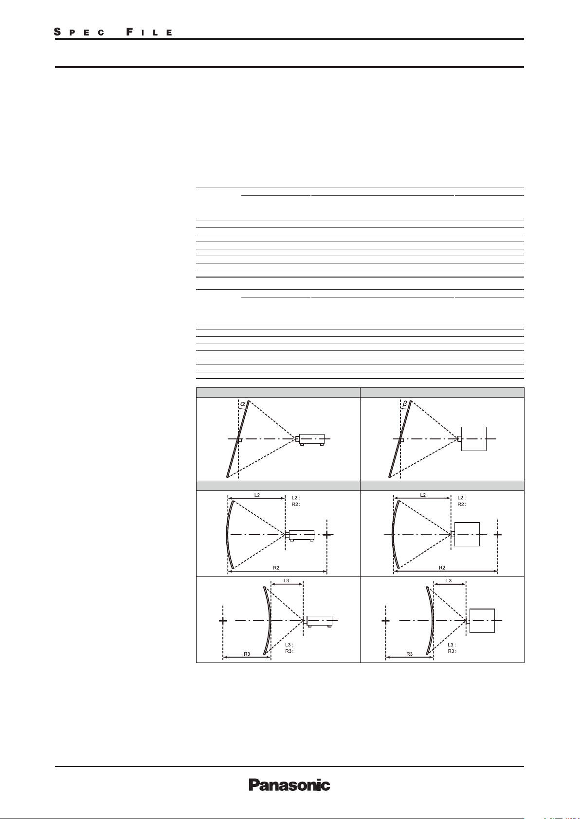
[VERTICAL KEYSTONE] (viewed from the side) [HORIZONTAL KEYSTONE] (viewed from above)
Screen
Screen
Vertical arc correction (viewed from the side) Horizontal arc correction (viewed from above)
Screen
Arc center
Screen
Projection distance
Arc radius
Projection distance
Arc radius
Screen
Arc center
Screen
Projection distance
Arc radius
Projection distance
Arc radius
Lens Shift Vertical
±55% (±44% with the ET-D75LE6/ET-D3LEW60), (+68-78% with the
ET-D75LE95), from center of screen, powered
Horizontal
±20% (±15% with the ET-D75LE6/ET-D3LEW60), (±12% with the
ET-D75LE95), from center of screen, powered
NOTE: Lens Shift function cannot be operated when used with the ET-D75LE50/ET-D3LEW50.
Installation Ceiling/oor, front /rear, free 360-degree installation
As of October 2018 3/18
RZ31KG_STZ_01_30/10/2018
Page 4
3-Chip DLP™ Projector
PT-RZ31K
Terminals
Power cord length
Cabinet materials
Dimensions (W ×H× D):
Weight*
Operation noise*
Safety Standards
11
3
RGB1 IN
R,G,B
Y, PB, PR (Y, CB, CR)
Y/C
VIDEO IN
RGB2 IN
R,G,B
Y, PB, PR (Y, CB, CR)
DVI-D IN
HDMI IN
SDI IN 1
SDI IN 2
DIGITAL LINK
3D SYNC1 IN/OUT /
MULTI PROJECTOR SYNC IN
3D SYNC2 OUT /
MULTI PROJECTOR SYNC OUT
SERIAL IN
SERIAL OUT
REMOTE 1 IN
REMOTE 1 OUT
REMOTE 2 IN
DIGITAL LINK/LAN
DC OUT 5V
BNC × 5
R: 0.7 Vp-p, 75 ohms,
G: 0.7 Vp-p (G: 1.0 Vp-p for sync on G), 75 ohms,
B: 0.7 Vp-p, 75 ohms
HD, VD/SYNC: TTL, high impedance, positive/negative automatic
Y: 1.0 Vp-p (including sync signal), P
Y: 1.0 Vp-p (including sync signal), C: 0.286 Vp-p, 75 ohms
BNC × 1, 1.0 Vp-p, 75 ohms
D-sub HD 15-pin (female) × 1
R: 0.7 Vp-p, 75 ohms,
G: 0.7 Vp-p (G: 1.0 Vp-p for sync on G), 75 ohms,
B: 0.7 Vp-p, 75 ohms
HD, VD/SYNC: TTL, high impedance, positive/negative automatic
Y: 1.0 Vp-p (including sync signal), PB/PR (CB/CR): 0.7 Vp-p, 75 ohms
DVI-D 24-pin ×1
Single link, DVI 1.0 compliant, HDCP compatible
HDMI 19-pin x1
HDCP compatible, Deep Color compatible
BNC × 1
SD-SDI signal SMPTE ST 259 compliant
HD-SDI signal SMPTE ST 292 compliant
3G-SDI signal SMPTE ST 424 compliant
Dual link HD-SDI (LINK-A) signal SMPTE ST 372 compliant
Dual link 3G-SDI (Link 1) signal SMPTE ST 425 compliant
BNC × 1
SD-SDI signal SMPTE ST 259 compliant
HD-SDI signal SMPTE ST 292 compliant
3G-SDI signal SMPTE ST 424 compliant
Dual link HD-SDI (LINK-B) signal SMPTE ST 372 compliant
Dual link 3G-SDI (Link 2) signal SMPTE ST 425 compliant
RJ-45
HDBaseT™ compliant, HDCP compatible, Deep Color compatible
BNC × 1, IN : TTL Hi-z OUT : TTL max10mA
BNC × 1, TTL max10mA
D-sub 9 pin × 1 for external control (RS-232C compliant)
D-sub 9 pin × 1 for link control
M3 stereo mini jack × 1 for wired remote control
M3 stereo mini jack × 1 for link control
D-sub 9 pin × 1 for external control (parallel)
RJ-45 x 1 (for network, DIGITAL LINK connection, 100Base-TX,
compatible with Art-Net, PJLink™ (class 1), Deep Color, HDCP)
USB connector (type A) x 2 for power supply only (DC 5V, Max.900mA)
3.0 m (9 ft 10 in) ft
Processed metal parts, Molded plastic
700 × 418*
(27-9/16 × 16-15/32 × 49-7/32 inches) (with protrusion parts)
700 × 373*10×1,070 mm
(27-9/16 × 14-11/16
79 kg (174.2 lbs)
49 dB
Class 1 (IEC 60825-1 Ed3 : 2014)
Risk Grope 3 (IEC 62471-5 Ed1 : 2015)
9
×1,250 mm
B/PR
(CB/CR): 0.7 Vp-p, 75 ohms
× 42-1/8 inches) (without protrusion parts)
As of October 2018 4/18
RZ31KG_STZ_01_30/10/2018
Page 5

3-Chip DLP™ Projector
PT-RZ31K
Operating temperature
Varies depending on operation mode setting.
HIGH/NORMAL
The operating temperature range is 0°C to 50°C (32 °F to 122 °F).
(Less than 1,400m (4,593 ft) above sea level)
The operating temperature range is 0°C to 45°C (32 °F to 113 °F).
(Less than 1,400m (4,593 ft) to 4,200m (13,780 ft) above sea level)
• If using at ambient operating temperatures of 35 °C (95 °F) or higher and at
less than 2,700m (8,858 ft) above sea level, or at ambient operating
temperatures of 25 °C (77 °F) or higher and between 2,700m (8,858 ft) and
4,200m (13,780 ft) above sea level, the brightness of the light source may
drop in order to protect the projector.
LONG LIFE 1/2/3
The operating temperature range is 0°C to 45°C (32 °F to 113 °F).
(Less than 2,700m (8,858 ft) above sea level)
• If using at ambient operating temperatures of 35 °C (95 °F) or higher,
the brightness of the light source may drop in order to protect the projector.
When using a smoke cut lter (regardless of operating mode)
0 °C to 40 °C (32 °F to 104 °F) Less than 1,400 m (4,953 ft) above sea level
Operating humidity
10%– 80% (no condensation)
Remote control unit
Power supply
Operation range
3 V DC (AA/R6 type battery ×2)
Approx. 30 m (985 in) ftwhen operated from directly in front of the
signal receptor
Dimensions (W × H × D)
Weight
47.5 × 181.5 × 27.5 mm (1-7/8 × 7-5/32 × 1-3/32 inches)
Approx. 150 g (5.3 oz) (including batteries)
Supplied accessories
Power cord (×3) Wireless/wired remote control unit (×1) Batteries for remote control (AA/R6 type × 2)
Lens drop-prevention screw (× 1) Replacement lter unit (ET-EMF330) (× 4) Lens hole cover (× 1)
Software CD-ROM (Logo Transfer Software, Multi Monitoring & Control Software) (× 1)
Optional accessories
Zoomlens (0.9–1.1:1) ET-D75LE6/ET-D3LEW60 Zoomlens (1.39–1.79:1) ET-D75LE10
12
Zoomlens (1.35–1.84:1) ET-D3LEW10*
Zoomlens (2.4–4.7:1) ET-D75LE30 Zoomlens (2.57–5.00:1) ET-D3LET30*
Zoomlens (1.7–2.4:1) ET-D75LE20/ET-D3LES20
12
Zoomlens (4.9–7.9:1) ET-D75LE40 Zoomlens (4.94–7.94:1) ET-D3LET40*12
Zoomlens (7.3–13.8:1) ET-D75LE8/ET-3LET80 Fixed-focus lens (0.7:1) ET-D75LE50/ET-D3LEW50
Fixed-focus lens (0.36:1) ET-D75LE95*12 Optional Fisheye Lens ET-D3LEF70*12
Lens Fixed Attachment ET-PLF10 Long life lter unit ET-EMFU330
Smoke cut lter ET-SFR330 Replacement lter unit ET-EMF330
Upgrade kit ET-UK20 Early Warning Software ET-SWA100
Auto Screen Adjustment Upgrade Kit
ET-CUK10
Auto Screen Adjustment Upgrade Kit (PC)
ET-CUK10P
Digital interface box ET-YFB100G Digital LINK Switcher ET-YFB200G
Applicable software
Logo Transfer Software
Smart Projector Control for iOS/Android™
Multi Monitoring & Control Software with Early Warning functions. (automatic free 90-day trial available)
*1 When the standby mode is set to ECO, network functions such as power on over the LAN network will not operate, and the serial output terminal
cannot be used. Also, only certain commands can be received for external control using the serial terminal.
*2 Around this time, light output will have decreased by approximately 50 %. IEC62087: 2008 Broadcast contents, Dynamic Contrast [3], under conditions
with 35 °C (95 °F), 700 m (2,297 ft) above sea level, and 0.15 mg/m3 of particulate matter. Estimated time until light output declines to 50 % varies
depending on environment.
*3 Measurement, measuring conditions, and method of notation all comply with ISO 21118 international standards.
*4 Average light-output value of all shipped products measured at center of screen.
*5 In AC200V, When using a projection lens other than ET-D75LE95.
*6 Pixel-Repetition signal(dot clock frequency 27.0MHz) only
*7 Only the vertical keystone correction angle can be corrected in the direction in which the projector body moves away from the screen.
*8 When [VERTICAL KEYSTONE] and [HORIZONTAL KEYSTONE] are used simultaneously, correction cannot be made exceeding total of 55°.
*9 With legs at shortest position.
*10 Without legs.
*11 Average value. May differ depending on the actual unit.
*12 For details on the optional lens, see the Spec File for each lens.
As of October 2018 5/18
RZ31KG_STZ_01_30/10/2018
Page 6
3-Chip DLP™ Projector
PT-RZ31K
[18-5/16]
[8-3/4]
290
[11-7/16]
210
[8-1/4]
20
[13/16]
[8-11/16]
951
[37-7/16]
1250
[49-7/32]
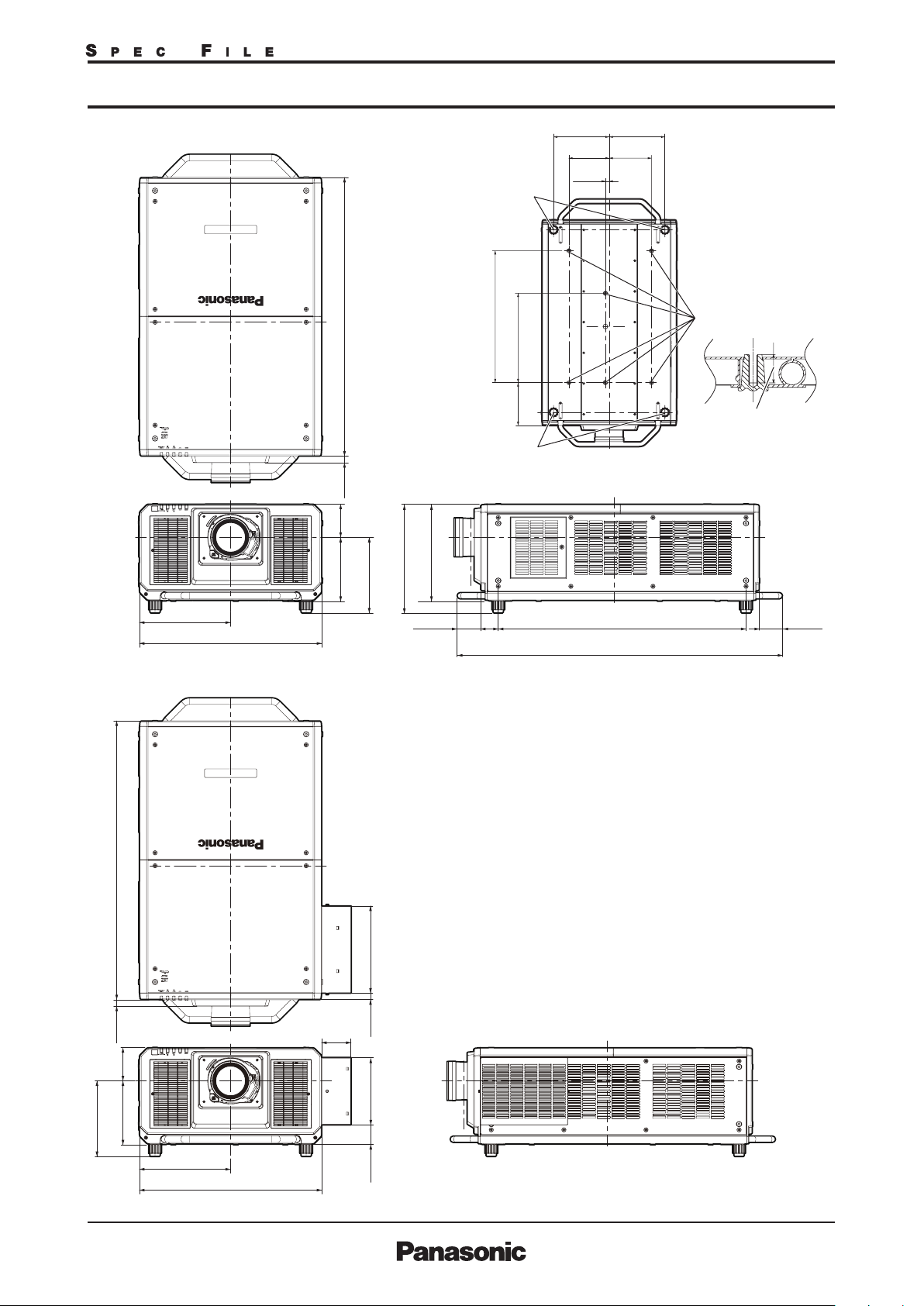
Dimensions
350
[13-25/32]
700
[27-9/16]
1070
[42-1/8]
25
[31/32]
[5]
127.5
245.5
[9-21/32]
290.5
[11-7/16]
418
[16-15/32]
[3-9/16]
Adjustable feet
686.5
Adjustable feet
Position of screw holes to fix
projector and adjustable feet
373
[14-11/16]
90
68
[2-11/16]
[27]
465
223
When the long-life filter unit (Model No.: ET-EMFU330, sold separately) is installed
290
[11-7/16]
220
Screw holes to fix the projector
(M10-30)
Tapping depth (common for 6
locations) 30 mm (1-3/16")
Use a torque screwdriver or Allen torque wrench to
tighten the fixing screws to their specified tightening
torques. Do not use elector impact screwdrivers.
89.2
[3-1/2]
1070
[42-1/8]
335.8
[13-7/32]
290.5
[11-7/16]
25
127.5
245.5
[31/32]
[5]
[9-21/32]
112.2
[4-13/32]
25.6
258.9
[1]
[10-3/16]
350
[13-25/32]
700
[27-9/16]
73.3
[2-7/8]
unit : mm (inch)
NOTE: This illustration is not drawn to scale.
As of October 2018 6/18
RZ31KG_STZ_01_30/10/2018
Page 7

3-Chip DLP™ Projector
Terminals
Power cord
PT-RZ31K
1
Remote 1 input
2
Remote 1 output
3
Remote 2 input
4
Serial input
5
Serial output
MULTI PROJECTOR SYNC IN
6
3D SYNC 1 IN/OUT
MULTI PROJECTOR SYNC OUT
7
3D SYNC 2 OUT
8
DC 1 output
9
DC 2 output
10
SDI 1 input
11
SDI 2 input
12
RGB 1 input
13
RGB 2 Input
14
DVI-D input
15
HDMI input
16
LAN/DIGITAL LINK connector
At power outlet
AC IN terminal
At projector
At projector
For 200V - 240VFor 200V - 240V
At power outlet
2P/3W 30 A 250 V
NEMA L6-30
At projector
At power outlet
At projector
Power outlets that can be used
2P/3W 30 A 250 V
Clock position 6h
For 110V - 120V
2P/3W 15 A 125 V
This projector supports AC 100 V to AC 120 V, and AC 200 V to AC 240 V as the power supply. A grounded
outlet supporting 30 A is required when using the projector with AC 200 V to AC 240 V. A grounded outlet
supporting 15 A is required when using the projector with AC 100 V to AC 120 V.
The shape of the usable outlet differs depending on the power supply. Following illustrations are examples.
NOTE
• The light output will decrease to approximately 1/3 when using the projector with AC 100 V to AC 120 V.
• The supplied power cords vary depending on the country or region where you purchased the product.
As of October 2018 7/18
RZ31KG_STZ_01_30/10/2018
Page 8

3-Chip DLP™ Projector
Standard setting-up position
Upper edge of projected image
PT-RZ31K
unit : mm (inch)
Projected image
L
*1
1070
(42-1/8)
L
HH
Lower edge of projected image
*1 When the lens protrudes to the maximum.
L
Projected image
This illustration is not drawn to scale.
182 mm (7-5/32) with the ET-D75LE6/ET-D3LEW60
95 mm (3-3/4) with the ET-D75LE10
91 mm (3-19/32) with the ET-D75LE20/ET-D3LES20
91 mm (3-19/32) with the ET-D75LE30
94 mm (3-11/16) with the ET-D75LE40
224 mm (8-13/16) with the ET-D75LE8/ET-D3LET80
173 mm (6-13/16) with the ET-D75LE50/ET-D3LEW50
Caution:
• All construction work should be done by a qualied technician.
• For details on the optional lens ,and lens of ET-D75LE95、ET-D3LEF70、ET-D3LEW10、ET-D3LET30、ET-D3LET40
see the Spec File for each lens.
As of October 2018 8/18
RZ31KG_STZ_01_30/10/2018
Page 9

3-Chip DLP™ Projector
PT-RZ31K
Projection distance for 16:10 aspect ratio screen
(ET
(ET-D75LE6/ET-D3LEW60/D75LE10/D75LE20/ET-D3LES20/D75LE30/D75LE40/D75LE8/ET-D3LET80/D75LE50/ET-D3LEW50)
Screen size
(diagonal)
[m] / [in]
/
1.78
/
2.03
/
2.29
/
2.54
100
/
3.05
120
/
3.81
150
/
5.08
200
/
6.35
250
/
7.62
300
/8.89
350
/
10.16
400
/
12.70
500
/
15.24
600
/17.78
700
/20.32
800
/22.86
900
/25.40
1000
1.62
1.86
2.10
2.34
2.82
3.55
4.75
5.96
7.17
8.37
9.58
ET-D75LE10
Zoom lens
1.90
2.19
2.47
2.76
3.32
4.18
5.60
7.02
8.44
9.86
11.28
14.12
16.96
2.46
2.83
3.20
3.56
4.30
5.40
7.24
9.07
10.91
12.74
14.58
18.25
21.93
ET-D75LE6
ET-D3LEW60
Zoom lens
min. max. min. max. min. max. min. max. min. max. min. max.
70
1.35
80
1.56
90
1.76
1.96
2.36
2.96
3.97
4.98
5.99
6.99
8.00
10.01
11.99
12.03
14.40
14.04 16.82 19.80 25.60 25.36 36.86 36.60 71.02 70.13 1 11.90 111.27 – 10.72 -0.47 – 9.90 0.57 – 8.86 4.71
16.06 19.23 22.64 29.27 29.00 42.14 41.84 81.19 80.17 1 27.91 127.23 – 12.27 -0.54 – 11.31 0.65 – 1 0.12 5.39
18.07 21.64 25.48 32.94 32.63 47.42 47.09 91.36 90.21 1 43.92 143.12 – 13.81 -0.61 – 12.72 0.73 – 1 1.39 6.06
20.08 24.06 28.33 36.61 36.27 52.70 52.33 101.53 100.25 159.93 159.13 – 15.35 -0.67 – 14.14 0.81 – 12.65 6.73
Distance to screen (L) Height from the edge of screen
Zoom Fixed-focus
20.56
23.55
26.54
29.53
35.51
44.47
59.41
74.36
89.30
104.24
119.19
149.08
178.96
ET-D75LE50
ET-D3LEW50
Fixed-focus
lens
1.01
1.16
1.32
1.47
1.78
2.24
3.01
3.78
4.56
5.33
6.10
7.64
9.18
ET-D75LE20
ET-D3LES20
Zoom lens
2.46
2.83
3.19
3.55
4.28
5.37
7.19
9.01
10.82
12.64
14.46
18.09
21.73
3.58
4.11
4.64
5.17
6.22
7.81
10.45
13.09
15.73
18.37
21.01
26.29
31.58
ET-D75LE30
Zoom lens
3.56
4.08
4.61
5.13
6.18
12.03
7.75
15.08
10.38
20.17
13.00
25.25
15.62
30.34
18.24
35.42
20.86
40.51
26.11
50.68
31.35
60.85
6.94
7.96
8.98
9.99
ET-D75LE40
Zoom lens
6.87
11.05
7.88
12.65
8.88
14.25
9.88
15.85
11.89
19.05
14.90
23.85
19.93
31.86
24.95
39.86
29.97
47.87
34.99
55.87
40.01
63.87
50.05
79.88
60.09
95.89
ET-D75LE8
ET-D3LET80
Zoom lens
10.78
12.38
13.97
15.57
18.76
23.54
31.52
39.49
47.47
55.44
63.42
79.37
95.32
to center of lens (H)
Zoom lenses
Except
ET-D75LE6
ET-D3LEW60
–
-0.05
–
-0.05
–
-0.06
–
-0.07
–
-0.08
–
-0.10
–
-0.14
–
-0.17
–
-0.20
–
-0.24
–
-0.27
–
-0.34
–
-0.40
0.99
1.13
1.27
1.41
1.70
2.12
2.83
3.53
4.24
4.95
5.65
7.07
8.48
Unit: meters
ET-D75LE6
ET-D3LEW60
–
0.06
0.89
–
0.07
1.01
–
0.07
1.14
–
0.08
1.27
–
0.10
1.52
–
0.12
1.90
–
0.16
2.53
–
0.20
3.16
–
0.24
3.80
–
0.28
4.43
–
0.32
5.06
–
0.40
6.33
–
0.49
7.59
Fixed-focus
ET-D75LE50
ET-D3LEW50
Zoom lens
0.47
0.54
0.61
0.67
0.81
1.01
1.35
1.68
2.02
2.36
2.69
3.37
4.04
Unit: feet
Screen size
(diagonal)
5.3
6.1
6.9
7.7
9.3
11.6
15.6
19.6
23.5
27.5
31.4
39.3
47.3
ET-D75LE10
Zoom lens
6.2
7.2
8.1
10.5
9.0
11.7
10.9
14.1
13.7
17.7
18.4
23.7
23.0
29.8
27.7
35.8
32.3
41.8
37.0
47.8
46.3
59.9
55.6
71.9
8.1
9.3
ET-D75LE6
ET-D3LEW60
Zoom lens
[m] / [in]
/
1.78
/
2.03
/
2.29
/
2.54
/
3.05
/
3.81
/
5.08
/
6.35
/
7.62
/8.89
/
10.16
/
12.70
/
15.24
/17.78
/20.32
/22.86
/25.40
•The value for L (distance to screen) varies slightly within ±5% depending on the zoom lens characteristics.
• At the shortest projection distance, the zoom lens characteristics may cause slight image distortion.
•When vertical keystone correction is u sed, the image is corrected in the direction that reduces its projected size.
NOTE:
When the ET-D75LE50/ET-D3LEW50 is mounted, the optical lens shift function cannot be used.
min. max. min. max. min. max. min. max. min. max. min. max.
70
4.4
80
5.1
90
5.8
100
6.4
120
7.7
150
9.7
200
13.0
250
16.3
300
19.6
22.9
350
400
26.2
500
32.9
600
39.5
46.1 55.2 65.0 84.0 83.2 120.9 120.1 233.0 230.1 3 67.1 365.1 – 35.2 -1.5 – 32.5 1.9 – 29.1 15.5
700
52.7 63.1 74.3 96.0 95.1 138.3 137.3 266.4 263.0 4 19.6 417.4 – 40.2 -1.8 – 37.1 2.1 – 33.2 17.7
800
59.3 71.0 83.6 108.1 107.1 155.6 1 54.5 299.7 296.0 472.2 469.5 – 45.3 -2.0 – 41.7 2 .4 – 37.4 19.9
900
65.9 78.9 92.9 120.1 119.0 172.9 1 71.7 333.1 328.9 524.7 522.1 – 50.4 -2.2 – 46.4 2 .7 – 41.5 22.1
1000
Distance to screen (L) Height from the edge of screen
Zoom Fixed-focus
67.5
77.3
87.1
96.9
116.5
145.9
194.9
244.0
293.0
342.0
391.0
489.1
587.1
ET-D75LE50
ET-D3LEW50
Fixed-focus
lens
3.3
3.8
4.3
4.8
5.8
7.3
9.8
12.3
14.9
17.5
20.0
25.1
30.1
ET-D75LE20
ET-D3LES20
Zoom lens
8.1
11.7
9.3
13.5
10.5
15.2
11.7
16.9
14.0
20.4
17.6
25.6
23.6
34.3
29.5
42.9
35.5
51.6
41.5
60.3
47.4
68.9
59.4
86.3
71.3
103.6
ET-D75LE30
Zoom lens
11.7
13.4
15.1
16.8
20.3
25.4
34.0
42.6
51.2
59.8
68.5
85.7
102.9
22.8
26.1
29.5
32.8
39.5
49.5
66.2
82.8
99.5
116.2
132.9
166.3
199.6
ET-D75LE40
Zoom lens
22.5
25.8
29.1
32.4
39.0
48.9
65.4
104.5
81.8
130.8
98.3
157.0
114.8
183.3
131.3
209.6
164.2
262.1
197.1
314.6
36.2
41.5
46.7
52.0
62.5
78.3
ET-D75LE8
ET-D3LET80
Zoom lens
35.4
40.6
45.8
51.1
61.5
77.2
103.4
129.6
155.7
181.9
208.1
260.4
312.7
to center of lens (H)
Zoom lenses
Except
ET-D75LE6
ET-D3LEW60
–
-0.2
3.2
–
-0.2
3.7
–
-0.2
4.2
–
-0.2
4.6
–
-0.3
5.6
–
-0.3
7.0
–
-0.4
9.3
–
-0.6
11.6
–
-0.7
13.9
–
-0.8
16.2
–
-0.9
18.6
–
-1.1
23.2
–
-1.3
27.8
ET-D75LE6
ET-D3LEW60
0.2
0.2
0.2
0.3
0.3
0.4
0.5
0.7
0.8
0.9
1.1
1.3
1.6
–
–
–
–
–
–
–
–
–
–
–
–
–
10.4
12.5
14.5
16.6
20.8
24.9
Fixed-focus
ET-D75LE50
ET-D3LEW50
Zoom lens
2.9
3.3
3.7
4.2
5.0
6.2
8.3
1.6
1.8
2.0
2.2
2.7
3.3
4.4
5.5
6.6
7.7
8.8
11.0
13.3
As of October 2018 9/18
RZ31KG_STZ_01_30/10/2018
Page 10

3-Chip DLP™ Projector
PT-RZ31K
Projection distance for 16:9 aspect ratio screen
(ET
(ET-D75LE6/ET-D3LEW60/D75LE10/D75LE20/ET-D3LES20/D75LE30/D75LE40/D75LE8/ET-D3LET80/D75LE50/ET-D3LEW50)
Screen size
(diagonal)
[m] / [in]
/
1.78
/
2.03
/
2.29
/
2.54
100
/
3.05
120
/
3.81
150
/
5.08
200
/
6.35
250
/
7.62
300
/8.89
350
/
10.16
400
/
12.70
500
/
15.24
600
/17.78
700
/20.32
800
/22.86
900
/25.40
1000
1.66
1.91
2.16
2.41
2.90
3.65
4.89
6.13
7.37
8.61
9.85
ET-D75LE10
Zoom lens
1.96
2.25
2.54
2.83
3.42
4.29
5.76
7.22
8.68
10.13
11.60
14.52
17.44
2.53
2.91
3.29
3.67
4.42
5.55
7.44
9.33
11.21
13.10
14.99
18.76
22.54
ET-D75LE6
ET-D3LEW60
Zoom lens
min. max. min. max. min. max. min. max. min. max. min. max.
70
1.39
80
1.60
90
1.81
2.01
2.43
3.05
4.08
5.12
6.15
7.19
8.22
10.29
12.33
12.36
14.81
14.43 17.29 20.36 26.31 26.07 37.89 37.62 73.00 72.09 1 15.02 114.38 – 11.02 -0.87 – 9.59 0.00 – 8.72 4.36
16.50 19.77 23.28 30.09 29.81 43.31 43.01 83.45 82.45 1 31.47 130.77 – 12.61 -1.00 – 10.96 0.00 – 9.96 4.98
18.57 22.25 26.20 33.86 33.54 48.74 48.40 93.90 92.73 1 47.92 147.17 – 14.19 -1.12 – 12.33 0.00 – 11.21 5.60
20.64 24.73 29.12 37.64 37.28 54.17 53.79 104.36 103.05 164.38 163.56 – 15.78 -1.25 – 13.70 0.00 – 12.45 6.23
Distance to screen (L) Height from the edge of screen
Zoom Fixed-focus
21.14
24.22
27.29
30.36
36.50
45.72
61.08
76.44
91.79
107.15
122.51
153.23
183.95
ET-D75LE50
ET-D3LEW50
Fixed-focus
lens
1.04
1.20
1.36
1.51
1.83
2.31
3.10
3.89
4.68
5.48
6.29
7.85
9.44
ET-D75LE20
ET-D3LES20
Zoom lens
2.53
2.91
3.28
3.65
4.40
5.52
7.39
9.26
11.13
12.99
14.86
18.60
22.33
3.68
4.23
4.77
5.31
6.40
8.03
10.74
13.46
16.17
18.88
21.60
27.03
32.46
ET-D75LE30
Zoom lens
3.66
4.20
4.74
5.28
10.28
6.36
12.37
7.97
15.50
10.67
20.73
13.36
25.96
16.06
31.18
18.75
36.41
21.45
41.64
26.84
52.09
32.23
62.54
7.14
8.19
9.23
ET-D75LE40
Zoom lens
7.07
11.36
8.10
13.00
9.13
14.65
10.16
16.29
12.23
19.58
15.32
24.52
20.48
32.75
25.64
40.97
30.80
49.20
35.96
57.43
41.12
65.65
51.44
82.11
61.76
98.56
ET-D75LE8
ET-D3LET80
Zoom lens
11.09
12.73
14.37
16.01
19.29
24.21
32.40
40.60
48.80
57.00
65.19
81.59
97.98
to center of lens (H)
Zoom lenses
Except
ET-D75LE6
ET-D3LEW60
–
-0.09
–
-0.10
–
-0.11
–
-0.13
–
-0.15
–
-0.19
–
-0.25
–
-0.31
–
-0.37
–
-0.44
–
-0.50
–
-0.62
–
-0.75
0.96
1.10
1.23
1.37
1.64
2.06
2.74
3.42
4.11
4.79
5.48
6.85
8.22
Unit: meters
ET-D75LE6
ET-D3LEW60
–
0.00
0.87
–
0.00
1.00
–
0.00
1.12
–
0.00
1.25
–
0.00
1.49
–
0.00
1.87
–
0.00
2.49
–
0.00
3.11
–
0.00
3.74
–
0.00
4.36
–
0.00
4.98
–
0.00
6.23
–
0.00
7.47
Fixed-focus
ET-D75LE50
ET-D3LEW50
Zoom lens
0.44
0.50
0.56
0.62
0.75
0.93
1.25
1.56
1.87
2.18
2.49
3.11
3.74
Unit: feet
Screen size
(diagonal)
5.5
6.3
7.1
7.9
9.5
12.0
16.0
20.1
24.2
28.2
32.3
40.4
48.6
ET-D75LE10
Zoom lens
6.4
7.4
8.3
10.8
9.3
12.0
11.2
14.5
14.1
18.2
18.9
24.4
23.7
30.6
28.5
36.8
33.3
43.0
38.0
49.2
47.6
61.6
57.2
73.9
8.3
9.6
ET-D75LE6
ET-D3LEW60
Zoom lens
[m] / [in]
/
1.78
/
2.03
/
2.29
/
2.54
/
3.05
/
3.81
/
5.08
/
6.35
/
7.62
/8.89
/
10.16
/
12.70
/
15.24
/17.78
/20.32
/22.86
/25.40
•The value for L (distance to screen) varies slightly within ±5% depending on the zoom lens characteristics.
• At the shortest projection distance, the zoom lens characteristics may cause slight image distortion.
•When vertical keystone correction is u sed, the image is corrected in the direction that reduces its projected size.
NOTE:
When the ET-D75LE50/ET-D3LEW50 is mounted, the optical lens shift function cannot be used.
min. max. min. max. min. max. min. max. min. max. min. max.
70
4.6
80
5.2
90
5.9
100
6.6
120
8.0
150
10.0
200
13.4
250
16.8
300
20.2
23.6
350
400
27.0
500
33.8
600
40.6
47.4 56.7 66.8 86.3 85.5 124.3 123.4 239.5 236.5 377.3 3 75.3 – 36.2 -2.9 – 31.5 0.0 – 28.6 14.3
700
54.1 64.8 76.4 98.7 97.8 142.1 141.1 273.8 270.5 431.3 4 29.0 – 41.4 -3.3 – 36.0 0.0 – 32.7 16.3
800
60.9 73.0 85.9 111.1 110.0 159.9 158.8 3 08.1 304.2 485.3 482.8 – 46.6 -3.7 – 40.4 0.0 – 36.8 18.4
900
67.7 81.1 95.5 123.5 122.3 177.7 176.5 3 42.4 338.1 539.3 536.6 – 51.8 -4.1 – 44.9 0.0 – 40.9 20.4
1000
Distance to screen (L) Height from the edge of screen
Zoom Fixed-focus
69.4
79.4
89.5
99.6
119.8
150.0
200.4
250.8
301.2
351.6
401.9
502.7
603.5
ET-D75LE50
ET-D3LEW50
Fixed-focus
lens
3.4
3.9
4.4
5.0
6.0
7.6
10.2
12.8
15.4
18.0
20.6
25.8
31.0
ET-D75LE20
ET-D3LES20
Zoom lens
8.3
12.1
9.5
13.9
10.8
15.6
12.0
17.4
14.4
21.0
18.1
26.3
24.2
35.2
30.4
44.1
36.5
53.1
42.6
62.0
48.8
70.9
61.0
88.7
73.3
106.5
ET-D75LE30
Zoom lens
12.0
13.8
15.5
17.3
20.8
26.2
35.0
43.8
52.7
61.5
70.4
88.0
105.7
23.4
26.9
30.3
33.7
40.6
50.9
68.0
85.2
102.3
119.5
136.6
170.9
205.2
ET-D75LE40
Zoom lens
23.2
26.6
30.0
33.3
40.1
50.3
67.2
107.4
84.1
134.4
101.1
161.4
118.0
188.4
134.9
215.4
168.8
269.4
202.6
323.4
37.3
42.7
48.1
53.5
64.2
80.4
ET-D75LE8
ET-D3LET80
Zoom lens
36.4
41.8
47.1
52.5
63.3
79.4
106.3
133.2
160.1
187.0
213.9
267.7
321.5
to center of lens (H)
Zoom lenses
Except
ET-D75LE6
ET-D3LEW60
–
-0.3
3.2
–
-0.3
3.6
–
-0.4
4.1
–
-0.4
4.5
–
-0.5
5.4
–
-0.6
6.7
–
-0.8
9.0
–
-1.0
11.2
–
-1.2
13.5
–
-1.4
15.7
–
-1.6
18.0
–
-2.0
22.5
–
-2.5
27.0
ET-D75LE6
ET-D3LEW60
0.0
0.0
0.0
0.0
0.0
0.0
0.0
0.0
0.0
0.0
0.0
0.0
0.0
–
–
–
–
–
–
–
–
–
–
–
–
–
Fixed-focus
ET-D75LE50
ET-D3LEW50
2.9
3.3
3.7
4.1
4.9
6.1
8.2
10.2
12.3
14.3
16.3
20.4
24.5
Zoom lens
1.4
1.6
1.8
2.0
2.5
3.1
4.1
5.1
6.1
7.2
8.2
10.2
12.3
As of October 2018 10/18
RZ31KG_STZ_01_30/10/2018
Page 11

3-Chip DLP™ Projector
PT-RZ31K
Calculation of the projection distance
For a screen size different from the above, use the equation below to calculate the projection distance.
Aspect ratio 16:10
Zoom lenses
ET-D75LE6
ET-D3LEW60
ET-D75LE10
minimum L (m) = (diagonal screen size in inches) × 0.0201 – 0.0566
maximum L (m) = (diagonal screen size in inches) × 0.0241 – 0.0736
minimum L (m) = (diagonal screen size in inches) × 0.0284 – 0.0857
maximum L (m) = (diagonal screen size in inches) × 0.0367 – 0.1085
ET-D75LE20
ET-D3LES20
ET-D75LE30
minimum L (m) = (diagonal screen size in inches) × 0.0364 – 0.0832
maximum L (m) = (diagonal screen size in inches) × 0.0528 – 0.1162
minimum L (m) = (diagonal screen size in inches) × 0.0524 – 0.1131
maximum L (m) = (diagonal screen size in inches) × 0.1017 – 0.1765
ET-D75LE40
minimum L (m) = (diagonal screen size in inches) × 0.1004 – 0.1577
maximum L (m) = (diagonal screen size in inches) × 0.1601 – 0.1615
ET-D75LE8
ET-D3LET80
minimum L (m) = (diagonal screen size in inches) × 0.1595 – 0.3862
maximum L (m) = (diagonal screen size in inches) × 0.2989 – 0.3598
Fixed-focus lens
ET-D75LE50/ET-D3LEW50
L (m) = (diagonal screen size in inches) × 0.0154 – 0.0713
Aspect ratio 16:9
Zoom lenses
ET-D75LE6
ET-D3LEW60
ET-D75LE10
ET-D75LE20
ET-D3LES20
ET-D75LE30
ET-D75LE40
ET-D75LE8
ET-D3LET80
Fixed-focus lens
ET-D75LE50/ET-D3LEW50
• Distances calculated w ith the above equations will include slight deviations.
minimum L (m) = (diagonal screen size in inches) × 0.0207 – 0.0566
maximum L (m) = (diagonal screen size in inches) × 0.0248 – 0.0736
minimum L (m) = (diagonal screen size in inches) × 0.0292 – 0.0857
maximum L (m) = (diagonal screen size in inches) × 0.0377 – 0.1085
minimum L (m) = (diagonal screen size in inches) × 0.0374 – 0.0832
maximum L (m) = (diagonal screen size in inches) × 0.0543 – 0.1162
minimum L (m) = (diagonal screen size in inches) × 0.0539 – 0.1131
maximum L (m) = (diagonal screen size in inches) × 0.1045 – 0.1765
minimum L (m) = (diagonal screen size in inches) × 0.1032 – 0.1577
maximum L (m) = (diagonal screen size in inches) × 0.1645 – 0.1615
minimum L (m) = (diagonal screen size in inches) × 0.1640 – 0.3862
maximum L (m) = (diagonal screen size in inches) × 0.3072 – 0.3598
L (m) = (diagonal screen size
in inches) × 0.0159 – 0.0713
Shift range
Lens Shift function allows to shift the position of a projected image as shown below.
When the lens except the ET-D75LE6,
•
ET-D3LEW60 is mounted
H
(Width of
projected image)
V
(Height of
projected image)
Standard postition of projected image
NOTE: Because the ET-D75LE50/ET-D3LEW50 is a fixed short-throw lens, the lens shift function cannot be used with it.
Caution
:
0.2H0.2H
0.55V
0.12V
0.12V
0.55V
• For details on the optional lens ,and lens of ET-D75LE95、ET-D3LEF70、ET-D3LEW10、ET-D3LET30、ET-D3LET40
see the Spec File for each lens.
As of October 2018 11/18
RZ31KG_STZ_01_30/10/2018
When the ET-D75LE6, ET-D3LEW60 is mounted
•
H
(Width of
projected image)
V
(Height of
projected image)
Standard postition of projected image
0.15H0.15H
0.12V
0.12V
0.44V
0.44V
Page 12

3-Chip DLP™ Projector
Installable angle
Install the projector at an angle within the range shown below.
FULL 360-degree projection
PT-RZ31K
360°
Vertical 360-deg.
Notes on projector placement and operation
Horizontal 360-deg. Tilting 360-deg.
360°
360°
(V&H combination)
• Prevent hot and cool air from the air conditioning system to blow directly to the ventilation ports (intake and
exhaust) of the projector.
500 mm (19-11/16") or longer 500 mm (19-11/16") or longer
500 mm (19-11/16") or longer
100 mm (3-15/16") or longer
• Do not install the projector in a confined space.
When installing the projector in a confined space, provide air conditioning or ventilation separately.
Exhaust heat may accumulate when the ventilation is not enough, triggering the protection circuit
of the projector.
As of October 2018 12/18
RZ31KG_STZ_01_30/10/2018
Page 13

3-Chip DLP™ Projector
Cautions when conducting lifting work
• Use the eyebolts only when temporarily lifting the projector such as when installing the projector.
• Use ISO standard eyebolts (commercially available) for the M10 with an underhead length of 18 mm (23/32")
to 30 mm (1-3/16"). Also use ISO standard parts for other components to lift the projector (wires, etc.).
• Lift the projector using the eyebolts attached to 4 locations on the same plane.
• Set the lifting angle to 60° or more.
60° or more
18 mm (23/32") - 30 mm (1-3/16")
PT-RZ31K
As of October 2018 13/18
RZ31KG_STZ_01_30/10/2018
Page 14

3-Chip DLP™ Projector
PT-RZ31K
List of RGB1, RGB2, DVI-D, HDMI, DigitalLink compatible signals
Compatible signal
"NTSC/NTSC4.43/
PAL-M/PAL60"
PAL/PAL-N/SECAM
480/60i
576/50i
480/60i
576/50i
480/60p
576/50p
720/60p
720/50p
1080/60i
1080/50i
1080/24p
1080/24sF
1080/25p
1080/30p
1080/60p
1080/50p
640x400/70
640 x 400/85
640 x 480/60
640 x 480/67
640 x 480/73
640 x 480/75
640 x 480/85
800 x 600/56
800 x 600/60
800 x 600/72
800 x 600/75
800 x 600/85
832 x 624/75
1024 x 768/50
1024 x 768/60
1024 x 768/70
1024 x 768/75
1024 x 768/82
1024 x 768/85
1024 x 768/100
1024 x 768/120
1152 x 864/60
1152 x 864/70
1152 x 864/75
1152 x 864/85
1152 x 870/75
1280 x 720/50
1280 x 720/60
1280 x 720/100
1280 x 720/120
1280 x 768/50
1280 x 768/60
1280 x 768/75
1280 x 768/85
1280 x 800/50
1280 x 800/60
1280 x 800/75
Resolu tion
(Dots)
720 x 480i
720 x 576i
720 x 480i
720 x 576i
720(1440) x 480i*
720(1440) x 576i*
720 x 480
720 x 576
1280 x 720
1280 x 720
1920 x 1080i
1920 x 1080i
1920 x 1080
1920 x 1080i
1920 x 1080
1920 x 1080
1920 x 1080
1920 x 1080
640 x 400
640 x 400
640 x 480
640 x 480
640 x 480
640 x 480
640 x 480
800 x 600
800 x 600
800 x 600
800 x 600
800 x 600
832 x 624
1024 x 768
1024 x 768
1024 x 768
1024 x 768
1024 x 768
1024 x 768
1024 x 768*
1024 x 768*
3
3
1152 x 864
1152 x 864
1152 x 864
1152 x 864
1152 x 870
1280 x 720
1280 x 720
1280 x 720*
1280 x 720*
3
3
1280 x 768
1280 x 768
1280 x 768*
2
1280 x 768
1280 x 768
1280 x 800
1280 x 800
1280 x 800*
2
1280 x 800
Scanning freq.
(KHz)
15.7
15.6
15.7
15.6
1
15.7
1
15.6
31.5
31.3
45.0
37.5
33.8
28.1
27.0
27.0
28.1
33.8
67.5
56.3
31.5
37.9
31.5
35.0
37.9
37.5
43.3
35.2
37.9
48.1
46.9
53.7
49.7
39.6
48.4
56.5
60.0
65.5
68.7
81.4
98.8
53.7
64.0
67.5
77.1
68.7
37.1
44.8
76.3
92.6
39.6
47.8
47.4
60.3
68.6
41.3
49.7
49.3
62.8
H
V
(Hz)
59.9
50.0
59.9
50.0
59.9
50.0
59.9
50.0
60.0
50.0
60.0
50.0
24.0
48.0
25.0
30.0
60.0
50.0
70.1
85.1
59.9
66.7
72.8
75.0
85.0
56.3
60.3
72.2
75.0
85.1
74.6
50.0
60.0
70.1
75.0
81.6
85.0
100.0
120.0
60.0
70.0
75.0
85.0
75.1
49.8
59.9
100.0
120.0
49.9
59.9
60.0
74.9
84.8
50.0
59.8
59.9
74.9
Dot
clock freq.
(MHz)
-
-
13.5
13.5
27.0
27.0
27.0
27.0
74.3
74.3
74.3
74.3
74.3
74.3
74.3
74.3
148.5
148.5
25.2
31.5
25.2
30.2
31.5
31.5
36.0
36.0
40.0
50.0
49.5
56.3
57.3
51.9
65.0
75.0
78.8
86.0
94.5
113.3
139.1
81.6
94.2
108.0
119.7
100.0
60.5
74.5
131.8
161.6
65.3
79.5
68.3
102.3
117.5
68.0
83.5
71.0
106.5
VIDEO
(RGB1)
䘟
䘟
-
-
-
-
-
-
-
-
-
-
-
-
-
-
-
-
-
-
-
-
-
-
-
-
-
-
-
-
-
-
-
-
-
-
-
-
-
-
-
-
-
-
-
-
-
-
-
-
-
-
-
-
-
-
-
Y/C
(RGB1)
䘟
䘟
-
-
-
-
-
-
-
-
-
-
-
-
-
-
-
-
-
-
-
-
-
-
-
-
-
-
-
-
-
-
-
-
-
-
-
-
-
-
-
-
-
-
-
-
-
-
-
-
-
-
-
-
-
-
-
As of October 2018 14/18
RZ31KG_STZ_01_30/10/2018
Input terminal
-
-
䘟
䘟
-
-
䘟
䘟
䘟
䘟
䘟
䘟
䘟
䘟
䘟
䘟
䘟
䘟
䘟
䘟
䘟
䘟
䘟
䘟
䘟
䘟
䘟
䘟
䘟
䘟
䘟
䘟
䘟
䘟
䘟
䘟
䘟
䘟
䘟
䘟
䘟
䘟
䘟
䘟
䘟
䘟
䘟
䘟
䘟
䘟
䘟
䘟
䘟
䘟
䘟
䘟
䘟
-
-
-
-
HDMI
DIGITALLINK
-
-
-
-
䘟
䘟
䘟
䘟
䘟
䘟
䘟
䘟
䘟
䘟
䘟
䘟
䘟
䘟
䘟
䘟
䘟
䘟
䘟
䘟
䘟
䘟
䘟
䘟
䘟
䘟
䘟
䘟
䘟
䘟
䘟
䘟
䘟
䘟
䘟
䘟
䘟
䘟
䘟
䘟
䘟
䘟
䘟
䘟
䘟
䘟
䘟
䘟
䘟
䘟
䘟
䘟
䘟
DVI-DRGB 2RGB 1
-
-
䘟
䘟
-
-
䘟
䘟
䘟
䘟
䘟
䘟
䘟
䘟
䘟
䘟
䘟
䘟
䘟
䘟
䘟
䘟
䘟
䘟
䘟
䘟
䘟
䘟
䘟
䘟
䘟
䘟
䘟
䘟
䘟
䘟
䘟
䘟
䘟
䘟
䘟
䘟
䘟
䘟
䘟
䘟
䘟
䘟
䘟
䘟
䘟
䘟
䘟
䘟
䘟
䘟
䘟
䘟
䘟
䘟
䘟
䘟
䘟
䘟
䘟
䘟
䘟
䘟
䘟
䘟
䘟
䘟
䘟
䘟
䘟
䘟
䘟
䘟
䘟
䘟
䘟
䘟
䘟
䘟
䘟
䘟
䘟
䘟
䘟
䘟
䘟
䘟
䘟
䘟
䘟
䘟
䘟
䘟
䘟
䘟
䘟
䘟
䘟
䘟
䘟
䘟
䘟
䘟
䘟
䘟
Page 15

3-Chip DLP™ Projector
PT-RZ31K
2
4
4
2
Scanning freq.
H
(KHz)
71.6
60.0
52.4
64.0
72.3
78.2
80.0
91.1
39.6
47.7
54.1
64.0
65.2
65.3
78.8
82.2
46.3
55.9
46.4
55.9
61.8
75.0
54.1
65.3
55.6
66.6
67.2
61.8
74.6
74.0
(Hz)
84.9
60.0
50.0
60.0
66.3
72.0
75.0
85.0
49.9
59.8
50.0
60.0
60.0
60.0
72.0
75.0
49.9
59.9
49.9
60.0
49.9
60.0
50.0
60.0
49.9
59.9
60.0
49.9
59.9
60.0
V
Compatible signal
1280 x 800/85
1280 x 960/60
1280 x 1024/50
1280 x 1024/60
1280 x 1024/66
1280 x 1024/72
1280 x 1024/75
1280 x 1024/85
1366 x 768/50
1366 x 768/60
1400 x 1050/50
Resolu tion
(Dots)
1280 x 800
1280 x 960
1280 x 1024
1280 x 1024
1280 x 1024
1280 x 1024
1280 x 1024
1280 x 1024
1366 x 768
1366 x 768
1400 x 1050
1400 x 1050
1400 x 1050/60
1400 x 1050
1400 x 1050
1400 x 1050/72
1400 x 1050/75
1440 x 900/50
1440 x 900/60
1600 x 900/50
1600 x 900/60
1600 x 1200/50
1600 x 1200/60
1680 x 1050/50
1680 x 1050/60
1920 x 1080/50
1920 x 1080/60
1920 x 1200/50
1920 x 1200/60
1920 x 1200/60RB
*1 Pixel-Repetition signal (dot clock frequency 27.0 MHz) only
*2 VESA CVT-RB (Reduced Blanking)-compliant.
*3 Image is displayed as 3D image in the frame sequential format when [3D INPUT FORMAT] is set to [AUTO].
To display images in 2D, set [3D INPUT FORMAT] to [NATIVE].
*4 Image resolution is reduced by the image processing circuit before projection.
1400 x 1050
1400 x 1050
1440 x 900
1440 x 900
1600 x 900
1600 x 900
1600 x 1200
1600 x 1200
1680 x 1050
1680 x 1050
1920 x 1080
1920 x 1080*
1920 x 1080*
1920 x 1200
1920 x 1200*
1920 x 1200*
Dot
clock freq.
(MHz)
122.5
108.0
88.0
108.0
125.0
135.1
135.0
157.5
69.0
85.5
99.9
108.0
122.6
121.8
149.3
155.9
86.8
106.5
96.5
119.0
131.5
162.0
119.5
146.3
141.5
138.5
173.0
158.3
193.3
154.0
VIDEO
(RGB1)
-
-
-
-
-
-
-
-
-
-
-
-
-
-
-
-
-
-
-
-
-
-
-
-
-
-
-
-
-
-
Y/C
(RGB1)
-
-
-
-
-
-
-
-
-
-
-
-
-
-
-
-
-
-
-
-
-
-
-
-
-
-
-
-
-
-
Input terminal
䘟
䘟
䘟
䘟
䘟
䘟
䘟
䘟
䘟
䘟
䘟
䘟
䘟
䘟
䘟
䘟
䘟
䘟
䘟
䘟
䘟
䘟
䘟
䘟
䘟
䘟
䘟
䘟
䘟
䘟
-
-
HDMI
DIGITALLINK
䘟
䘟
䘟
䘟
䘟
䘟
䘟
䘟
䘟
䘟
䘟
䘟
䘟
䘟
䘟
䘟
䘟
䘟
䘟
䘟
䘟
䘟
䘟
䘟
䘟
䘟
-
䘟
-
䘟
DVI-DRGB 2RGB 1
䘟
䘟
䘟
䘟
䘟
䘟
䘟
䘟
䘟
䘟
䘟
䘟
䘟
䘟
䘟
䘟
䘟
䘟
䘟
䘟
䘟
䘟
䘟
䘟
䘟
䘟
䘟
䘟
䘟
䘟
䘟
䘟
䘟
䘟
䘟
䘟
䘟
䘟
䘟
䘟
䘟
䘟
䘟
䘟
䘟
䘟
䘟
䘟
䘟
䘟
䘟
䘟
䘟
䘟
䘟
䘟
䘟
䘟
List of SDI compatible signals
•Single link
480/60i
576/50i
720/60p
720/50p
1080/60i
1080/50i
1080/24p
Resolu tion
(Dots)
720 x 480i
720 x 576i
1280 x 720
1280 x 720
1920 x 1080i
1920 x 1080i
1920 x 1080i
1920 x 1080i
1920 x 1080i
1920 x 1080i
1920 x 1080i
1920 x 1080i
1920 x 1080i
1920 x 1080i
1920 x 1080
1920 x 1080
1920 x 1080
1920 x 1080
1920 x 1080
Scanning freq.
H (KHz)V (Hz)
15.7
15.6
45.0
37.5
33.8
33.8
33.8
33.8
33.8
28.1
28.1
28.1
28.1
28.1
27.0
27.0
27.0
27.0
27.0
59.9
50.0
60.0*
50.0
60.0*
60.0*
60.0*
60.0*
60.0*
50.0
50.0
50.0
50.0
50.0
24.0*
24.0*
24.0*
24.0*
24.0*
As of October 2018 15/18
RZ31KG_STZ_01_30/10/2018
1
1
1
1
1
1
1
1
1
1
1
Dot clock
freq. (MHz)
27.0
27.0
74.3
74.3
74.3
74.3
74.3
74.3
74.3
74.3
74.3
74.3
74.3
74.3
74.3
74.3
74.3
74.3
74.3
Format Color space SamplingCompatible signal
SD-SDI
SD-SDI
HD-SDI
HD-SDI
HD-SDI
3G-SDI Level-A
3G-SDI Level-B
3G-SDI Level-A
3G-SDI Level-B
HD-SDI
3G-SDI Level-A
3G-SDI Level-B
3G-SDI Level-A
3G-SDI Level-B
HD-SDI
3G-SDI Level-A
3G-SDI Level-B
3G-SDI Level-A
3G-SDI Level-B
YC
BCR
YCBCR
YPBPR
YPBPR
YPBPR
RGB
RGB
RGB
RGB
YP
BPR
RGB
RGB
RGB
RGB
YP
BPR
RGB
RGB
RGB
RGB
4:2:2 10bit
4:2:2 10bit
4:2:2 10bit
4:2:2 10bit
4:2:2 10bit
4:4:4 10bit
4:4:4 10bit
4:4:4 12bit
4:4:4 12bit
4:2:2 10bit
4:4:4 10bit
4:4:4 10bit
4:4:4 12bit
4:4:4 12bit
4:2:2 10bit
4:4:4 10bit
4:4:4 10bit
4:4:4 12bit
4:4:4 12bit
Page 16

3-Chip DLP™ Projector
PT-RZ31K
Resolu tion
(Dots)
1920 x 1080i
1920 x 1080i
1080/24sF
1920 x 1080i
1920 x 1080i
1920 x 1080i
1920 x 1080
1920 x 1080
1080/25p
1920 x 1080
1920 x 1080
1920 x 1080
1920 x 1080
1920 x 1080
1080/30p
1920 x 1080
1920 x 1080
1920 x 1080
1080/60p
1080/50p
1920 x 1080
1920 x 1080
1920 x 1080
1920 x 1080
2048 x 1080
2048 x 1080
2K/24p
2048 x 1080
2048 x 1080
2048 x 1080
2048 x 1080
2048 x 1080
2048 x 1080
2K/25p
2048 x 1080
2048 x 1080
2048 x 1080
2048 x 1080
2048 x 1080
2048 x 1080
2K/30p
2048 x 1080
2048 x 1080
2048 x 1080
2048 x 1080
2K/48p
2K/50p
2K/60p
*1 㻌㻯㼛㼙㼜㼍㼠㼕㼎㼘㼑㻌㼣㼕㼠㼔㻌㼂㻱㻾㼀㻵㻯㻭㻸㻌㻿㻯㻭㻺㻌㻲㻾㻱㻽㼁㻱㻺㻯㼅㻌㻝㻛㻝㻚㻜㻜㻝
2048 x 1080
2048 x 1080
2048 x 1080
2048 x 1080
2048 x 1080
2048 x 1080
H (KHz)V (Hz)
27.0
27.0
27.0
27.0
27.0
28.1
28.1
28.1
28.1
28.1
33.8
33.8
33.8
33.8
33.8
67.5
67.5
56.3
56.3
27.0
27.0
27.0
27.0
27.0
27.0
28.1
28.1
28.1
28.1
28.1
28.1
33.8
33.8
33.8
33.8
33.8
33.8
54.0
54.0
56.3
56.3
67.5
67.5
Scanning freq.
48.0*1
48.0*1
48.0*1
48.0*1
48.0*1
25.0
25.0
25.0
25.0
25.0
30.0*1
30.0*1
30.0*1
30.0*1
30.0*1
60.0*1
60.0*1
50.0
50.0
24.0*
24.0*
24.0*
24.0*
24.0*
24.0*
25.0
25.0
25.0
25.0
25.0
25.0
30.0*
30.0*
30.0*
30.0*
30.0*
30.0*
48.0*
48.0*
50.0
50.0
60.0*
60.0*
1
1
1
1
1
1
1
1
1
1
1
1
1
1
1
1
Dot clock
freq. (MHz)
74.3
74.3
74.3
74.3
74.3
74.3
74.3
74.3
74.3
74.3
74.3
74.3
74.3
74.3
74.3
148.5
148.5
148.5
148.5
74.3
74.3
74.3
74.3
74.3
74.3
74.3
74.3
74.3
74.3
74.3
74.3
74.3
74.3
74.3
74.3
74.3
74.3
148.5
148.5
148.5
148.5
148.5
148.5
Format Color space SamplingCompatible signal
HD-SDI
3G-SDI Level-A
3G-SDI Level-B
3G-SDI Level-A
3G-SDI Level-B
HD-SDI
3G-SDI Level-A
3G-SDI Level-B
3G-SDI Level-A
3G-SDI Level-B
HD-SDI
3G-SDI Level-A
3G-SDI Level-B
3G-SDI Level-A
3G-SDI Level-B
3G-SDI Level-A
3G-SDI Level-B
3G-SDI Level-A
3G-SDI Level-B
3G-SDI Level-A
3G-SDI Level-B
3G-SDI Level-A
3G-SDI Level-B
3G-SDI Level-A
3G-SDI Level-B
3G-SDI Level-A
3G-SDI Level-B
3G-SDI Level-A
3G-SDI Level-B
3G-SDI Level-A
3G-SDI Level-B
3G-SDI Level-A
3G-SDI Level-B
3G-SDI Level-A
3G-SDI Level-B
3G-SDI Level-A
3G-SDI Level-B
3G-SDI Level-A
3G-SDI Level-B
3G-SDI Level-A
3G-SDI Level-B
3G-SDI Level-A
3G-SDI Level-B
YP
BPR
RGB
RGB
RGB
RGB
YP
BPR
RGB
RGB
RGB
RGB
YP
BPR
RGB
RGB
RGB
RGB
YP
BPR
YPBPR
YPBPR
YPBPR
RGB
RGB
RGB
RGB
XYZ
XYZ
RGB
RGB
RGB
RGB
XYZ
XYZ
RGB
RGB
RGB
RGB
XYZ
XYZ
YP
BPR
YPBPR
YPBPR
YPBPR
YPBPR
YPBPR
4:2:2 10bit
4:4:4 10bit
4:4:4 10bit
4:4:4 12bit
4:4:4 12bit
4:2:2 10bit
4:4:4 10bit
4:4:4 10bit
4:4:4 12bit
4:4:4 12bit
4:2:2 10bit
4:4:4 10bit
4:4:4 10bit
4:4:4 12bit
4:4:4 12bit
4:2:2 10bit
4:2:2 10bit
4:2:2 10bit
4:2:2 10bit
4:4:4 10bit
4:4:4 10bit
4:4:4 12bit
4:4:4 12bit
4:4:4 12bit
4:4:4 12bit
4:4:4 10bit
4:4:4 10bit
4:4:4 12bit
4:4:4 12bit
4:4:4 12bit
4:4:4 12bit
4:4:4 10bit
4:4:4 10bit
4:4:4 12bit
4:4:4 12bit
4:4:4 12bit
4:4:4 12bit
4:2:2 10bit
4:2:2 10bit
4:2:2 10bit
4:2:2 10bit
4:2:2 10bit
4:2:2 10bit
List of SDI compatible signals
•Dual link
1080/60i
1080/50i
1080/24p
1080/24sF
1080/25p
1080/30p
Resolu tion
(Dots)
1920 x 1080i
1920 x 1080i
1920 x 1080i
1920 x 1080i
1920 x 1080
1920 x 1080
1920 x 1080i
1920 x 1080i
1920 x 1080
1920 x 1080
1920 x 1080
1920 x 1080
Scanning freq.
H (KHz)V (Hz)
33.8
33.8
28.1
28.1
27.0
27.0
27.0
27.0
28.1
28.1
33.8
33.8
60.0*
60.0*
50.0
50.0
24.0*
24.0*
48.0*
48.0*
25.0
25.0
30.0*
30.0*
As of October 2018 16/18
RZ31KG_STZ_01_30/10/2018
1
1
1
1
1
1
1
1
Dot clock
freq. (MHz)
74.3
74.3
74.3
74.3
74.3
74.3
74.3
74.3
74.3
74.3
74.3
74.3
Format Color space SamplingCompatible signal
HD-SDI
HD-SDI
HD-SDI
HD-SDI
HD-SDI
HD-SDI
HD-SDI
HD-SDI
HD-SDI
HD-SDI
HD-SDI
HD-SDI
RGB
RGB
RGB
RGB
RGB
RGB
RGB
RGB
RGB
RGB
RGB
RGB
4:4:4 10bit
4:4:4 12bit
4:4:4 10bit
4:4:4 12bit
4:4:4 10bit
4:4:4 12bit
4:4:4 10bit
4:4:4 12bit
4:4:4 10bit
4:4:4 12bit
4:4:4 10bit
4:4:4 12bit
Page 17

3-Chip DLP™ Projector
PT-RZ31K
Resolu tion
(Dots)
1920 x 1080
1920 x 1080
1920 x 1080
1080/60p
1920 x 1080
1920 x 1080
1920 x 1080
1920 x 1080
1920 x 1080
1920 x 1080
1920 x 1080
1920 x 1080
1080/50p
1920 x 1080
1920 x 1080
1920 x 1080
1920 x 1080
1920 x 1080
2048 x 1080
2K/24p
2048 x 1080
2048 x 1080
2048 x 1080
2048 x 1080
2048 x 1080
2K/48p
2048 x 1080
2048 x 1080
2048 x 1080
2048 x 1080
2048 x 1080
2048 x 1080
2048 x 1080
2048 x 1080
2K/50p
2048 x 1080
2048 x 1080
2048 x 1080
2048 x 1080
2048 x 1080
2048 x 1080
2048 x 1080
2048 x 1080
2K/60p
2048 x 1080
2048 x 1080
2048 x 1080
2048 x 1080
2048 x 1080
*1 㻌㻯㼛㼙㼜㼍㼠㼕㼎㼘㼑㻌㼣㼕㼠㼔㻌㼂㻱㻾㼀㻵㻯㻭㻸㻌㻿㻯㻭㻺㻌㻲㻾㻱㻽㼁㻱㻺㻯㼅㻌㻝㻛㻝㻚㻜㻜㻝
H (KHz)V (Hz)
67.5
67.5
67.5
67.5
67.5
67.5
67.5
67.5
56.3
56.3
56.3
56.3
56.3
56.3
56.3
56.3
27.0
27.0
27.0
54.0
54.0
54.0
54.0
54.0
54.0
54.0
54.0
56.3
56.3
56.3
56.3
56.3
56.3
56.3
56.3
67.5
67.5
67.5
67.5
67.5
67.5
67.5
67.5
Scanning freq.
60.0*
60.0*
60.0*
60.0*
60.0*
60.0*
60.0*
60.0*
50.0
50.0
50.0
50.0
50.0
50.0
50.0
50.0
24.0*
24.0*
24.0*
48.0*
48.0*
48.0*
48.0*
48.0*
48.0*
48.0*
48.0*
50.0
50.0
50.0
50.0
50.0
50.0
50.0
50.0
60.0*
60.0*
60.0*
60.0*
60.0*
60.0*
60.0*
60.0*
1
1
1
1
1
1
1
1
1
1
1
1
1
1
1
1
1
1
1
1
1
1
1
1
1
1
1
Dot clock
freq. (MHz)
148.5
148.5
148.5
148.5
148.5
148.5
148.5
148.5
148.5
148.5
148.5
148.5
148.5
148.5
148.5
148.5
74.25
74.25
74.25
148.5
148.5
148.5
148.5
148.5
148.5
148.5
148.5
148.5
148.5
148.5
148.5
148.5
148.5
148.5
148.5
148.5
148.5
148.5
148.5
148.5
148.5
148.5
148.5
Format Color space SamplingCompatible signal
3G-SDI Level-A
3G-SDI Level-B
3G-SDI Level-A
3G-SDI Level-B
3G-SDI Level-A
3G-SDI Level-B
3G-SDI Level-A
3G-SDI Level-B
3G-SDI Level-A
3G-SDI Level-B
3G-SDI Level-A
3G-SDI Level-B
3G-SDI Level-A
3G-SDI Level-B
3G-SDI Level-A
3G-SDI Level-B
HD-SDI
HD-SDI
HD-SDI
3G-SDI Level-A
3G-SDI Level-B
3G-SDI Level-A
3G-SDI Level-B
3G-SDI Level-A
3G-SDI Level-B
3G-SDI Level-A
3G-SDI Level-B
3G-SDI Level-A
3G-SDI Level-B
3G-SDI Level-A
3G-SDI Level-B
3G-SDI Level-A
3G-SDI Level-B
3G-SDI Level-A
3G-SDI Level-B
3G-SDI Level-A
3G-SDI Level-B
3G-SDI Level-A
3G-SDI Level-B
3G-SDI Level-A
3G-SDI Level-B
3G-SDI Level-A
3G-SDI Level-B
YP
BPR
YPBP
YPBPR
YPBP
RGB
RGB
RGB
RGB
YP
BPR
YPBPR
YPBPR
YPBPR
RGB
RGB
RGB
RGB
RGB
RGB
XYZ
YP
BPR
YPBP
YPBPR
YPBPR
RGB
RGB
RGB
RGB
YP
BPR
YPBPR
YPBP
YPBPR
RGB
RGB
RGB
RGB
YP
BPR
YPBPR
YPBPR
YPBPR
RGB
RGB
RGB
RGB
R
R
R
R
4:4:4 10bit
4:4:4 10bit
4:4:4 12bit
4:4:4 12bit
4:4:4 10bit
4:4:4 10bit
4:4:4 12bit
4:4:4 12bit
4:4:4 10bit
4:4:4 10bit
4:4:4 12bit
4:4:4 12bit
4:4:4 10bit
4:4:4 10bit
4:4:4 12bit
4:4:4 12bit
4:4:4 10bit
4:4:4 12bit
4:4:4 12bit
4:4:4 10bit
4:4:4 10bit
4:4:4 12bit
4:4:4 12bit
4:4:4 10bit
4:4:4 10bit
4:4:4 12bit
4:4:4 12bit
4:4:4 10bit
4:4:4 10bit
4:4:4 12bit
4:4:4 12bit
4:4:4 10bit
4:4:4 10bit
4:4:4 12bit
4:4:4 12bit
4:4:4 10bit
4:4:4 10bit
4:4:4 12bit
4:4:4 12bit
4:4:4 10bit
4:4:4 10bit
4:4:4 12bit
4:4:4 12bit
List of simultaneous input 2D compatible signals
2D compatible signal
1080/60p
1080/50p
1366 x 768/50
1366 x 768/60
1400 x 1050/50
1400 x 1050/60
1920 x 1080/50
1920 x 1080/60
1920 x 1200/50
1920 x 1200/60
Resolu tion
(Dots)
1 920 x 1 080
1 920 x 1 080
1 366 x 768
1 366 x 768
1 400 x 1 050
1 400 x 1 050
1 920 x 1 080
1 920 x 1 080
1 920 x 1 200
1 920 x 1 200
Scanning freq.
H (KHz)V (Hz)
67.5
56.3
39.6
47.7
54.1
65.3
55.6
66.6
61.8
74.0
60
50
49.9
59.8
50
60
49.9
59.9
49.9
60
As of October 2018 17/18
RZ31KG_STZ_01_30/10/2018
Dot clock
freq. (MHz)
148.5
148.5
69
85.5
99.9
121.8
141.5
138.5
158.3
154
HDMI/DVI SDI 1/SDI 2
䘟
䘟
䘟
䘟
䘟
䘟
䘟
䘟
䘟
䘟
䘟
䘟
-
-
-
-
-
-
-
-
Page 18

3-Chip DLP™ Projector
List of compatible 3D signals
PT-RZ31K
FP: Frame packing format
SBS: Side by side format
TB: Top and bottom format
LBL: Line by line format
FS: Frame sequential format
3D
Compatible
signal
720/60p
720/50p
1080/60i
1080/50i
1080/24p
1080/24sF
1080/25p
1080/30p
1080/60p
1080/50p
640 x 480
800 x 600
1024 x 768
1152 x 864
1280 x 720
1280 x 768
1280 x 800
1280 x 96
1280 x 1024
1366 x 768
1400 x 1050
1440 x 900
1600 x 900
1600 x 1200
1680 x 1050
1920 x 1080
1920 x 1200
*1 Supports half.
*2 VESA CVT RB (Reduced Blanking) compliant
Resolu tion
1280 x 720
1280 x 720
1920 x 1080i
1920 x 1080i
1920 x 1080
1920 x 1080i
1920 x 1080
1920 x 1080
1920 x 1080
1920 x 1080
640 x 480
640 x 480
1024 x 768
1024 x 768
1024 x 768
1024 x 768
1152 x 864
1280 x 720
1280 x 720
1280 x 720
1280 x 720
1280 x 768
1280 x 768
1280 x 768*
1280 x 800
1280 x 800
1280 x 800*
0
1280 x 960
1280 x 1024
1280 x 1024
1366 x 768
1366 x 768
1400 x 1050
1400 x 1050
1400 x 1050
1400 x 1050
1440 x 900
1440 x 900
1600 x 900
1600 x 900
1600 x 1200
1600 x 1200
1680 x 1050
1680 x 1050
1920 x 1080
1920 x 1080*
1920 x 1200
1920 x 1200*
(Dots)
Scanning freq.
H
(KHz)V(Hz)
45.0
37.5
33.8
28.1
27.0
27.0
28.1
33.8
67.5
56.3
31.5
37.9
39.6
48.4
81.4
98.8
53.7
37.1
44.8
76.3
92.6
39.6
47.8
2
47.4
41.3
49.7
2
49.3
60.0
52.4
64.0
47.7
39.6
54.1
64.0
65.2
65.3
55.9
46.3
46.4
55.9
75.0
61.8
65.3
54.1
55.6
2
66.6
61.8
2
74.0
60.0
50.0
60.0
50.0
24.0
24.0
25.0
30.0
60.0
50.0
59.9
60.3
50.0
60.0
100.0
120.0
60.0
49.8
59.9
100.0
120.0
49.9
59.9
60.0
50.0
59.8
59.9
60.0
50.0
60.0
59.8
49.9
50.0
60.0
60.0
60.0
59.9
49.9
49.9
60.0
60.0
49.9
60.0
50.0
49.9
59.9
49.9
60.0
3G: 3G-SDI Level B simultaneous format
H-D: HDMI & DVI-D input simultaneous format
R1-2: RGB1 & RGB2 input simultaneous format
S1-2: SDI1 & SDI2 input simultaneous format
Dot
clock freq.
(MHz)
74.3
74.3
74.3
74.3
74.3
74.3
74.3
74.3
148.5
148.5
25.2
40.0
51.9
65.0
113.3
139.1
81.6
60.5
74.5
131.8
161.6
65.3
79.5
68.3
68.0
83.5
71.0
108.0
88.0
108.0
85.5
69.0
99.9
108.0
122.6
121.8
106.5
86.8
96.5
119.0
162.0
131.5
146.3
119.5
141.5
138.5
158.3
154.0
HDMI DVIRGB1/RGB2 SDI1/SDI2
FP SBS*
䘟
䘟
䘟
䘟
䘟
䘟
䘟
䘟
䘟
䘟
㻙
㻙
㻙
㻙
䘟
㻙
䘟
㻙
㻙
㻙
㻙
㻙
㻙
㻙
㻙
㻙
㻙
㻙
㻙
㻙
㻙
㻙
㻙
㻙
㻙
㻙
㻙
㻙
㻙
㻙
㻙
㻙
㻙
㻙
㻙
㻙
㻙
㻙
㻙
㻙
㻙
㻙
㻙
㻙
㻙
1
TB TB LBLFS FS TB LBLSBS*1TB LBLFS 3G
䘟
䘟
㻙
㻙
䘟
㻙
㻙
㻙
㻙
㻙
㻙
䘟
䘟
㻙
㻙
㻙
㻙
㻙
㻙
㻙
㻙
㻙
㻙
㻙
㻙
㻙
㻙
㻙
㻙
㻙
㻙
㻙
㻙
㻙
㻙
㻙
㻙
㻙
㻙
㻙
㻙
㻙
㻙
㻙
㻙
㻙
㻙
㻙
㻙
㻙
㻙
㻙
㻙
㻙
㻙
㻙
㻙
㻙
㻙
㻙
㻙
㻙
㻙
㻙
㻙
㻙
㻙
㻙
㻙
㻙
㻙
㻙
㻙
㻙
㻙
㻙
㻙
㻙
㻙
㻙
㻙
㻙
㻙
㻙
㻙
㻙
㻙
㻙
㻙
1
SBS*
㻙
䘟
䘟
䘟
㻙
䘟
䘟
䘟
㻙
䘟
䘟
㻙
㻙
䘟
䘟
㻙
㻙
䘟
䘟
㻙
㻙
䘟
䘟
㻙
㻙
䘟
䘟
㻙
㻙
䘟
䘟
㻙
㻙
䘟
䘟
㻙
㻙
䘟
䘟
㻙
㻙
䘟
㻙
㻙
㻙
䘟
㻙
㻙
㻙
䘟
㻙
㻙
㻙
䘟
㻙
㻙
䘟
㻙
㻙
㻙
䘟
㻙
㻙
㻙
㻙
䘟
㻙
㻙
㻙
䘟
㻙
㻙
㻙
䘟
㻙
㻙
䘟
㻙
㻙
㻙
䘟
㻙
㻙
㻙
㻙
䘟
㻙
㻙
㻙
䘟
㻙
㻙
㻙
䘟
㻙
㻙
㻙
䘟
㻙
㻙
㻙
䘟
㻙
㻙
㻙
䘟
㻙
㻙
㻙
䘟
㻙
㻙
㻙
䘟
㻙
㻙
㻙
䘟
㻙
㻙
㻙
䘟
㻙
㻙
㻙
䘟
㻙
㻙
㻙
䘟
㻙
㻙
㻙
䘟
㻙
㻙
㻙
䘟
㻙
㻙
㻙
䘟
㻙
㻙
㻙
䘟
㻙
㻙
㻙
䘟
㻙
㻙
㻙
䘟
㻙
㻙
㻙
䘟
㻙
㻙
㻙
䘟
㻙
㻙
㻙
䘟
㻙
㻙
㻙
䘟
㻙
㻙
㻙
䘟
㻙
㻙
㻙
䘟
㻙
㻙
㻙
䘟
㻙
㻙
㻙
䘟
㻙
㻙
㻙
䘟
㻙
䘟
1
SBS*
㻙
䘟
䘟
㻙
䘟
䘟
㻙
䘟
䘟
㻙
䘟
䘟
㻙
䘟
䘟
㻙
䘟
䘟
㻙
䘟
䘟
㻙
䘟
䘟
㻙
䘟
䘟
㻙
䘟
䘟
㻙
䘟
㻙
㻙
䘟
㻙
㻙
䘟
㻙
㻙
䘟
㻙
䘟
㻙
㻙
䘟
㻙
㻙
㻙
䘟
㻙
㻙
䘟
㻙
㻙
䘟
㻙
䘟
㻙
㻙
䘟
㻙
㻙
㻙
䘟
㻙
㻙
䘟
㻙
㻙
䘟
㻙
㻙
䘟
㻙
㻙
䘟
㻙
㻙
䘟
㻙
㻙
䘟
㻙
㻙
䘟
㻙
㻙
䘟
㻙
㻙
䘟
㻙
㻙
䘟
㻙
㻙
䘟
㻙
㻙
䘟
㻙
㻙
䘟
㻙
㻙
䘟
㻙
㻙
䘟
㻙
㻙
䘟
㻙
㻙
䘟
㻙
㻙
䘟
㻙
㻙
䘟
㻙
㻙
䘟
㻙
㻙
䘟
㻙
㻙
䘟
㻙
㻙
䘟
㻙
㻙
䘟
㻙
㻙
䘟
㻙
㻙
䘟
㻙
H-D R1-2 S1-2
䘟
䘟
䘟
䘟
䘟
䘟
䘟
㻙
䘟
䘟
䘟
䘟
䘟
㻙
䘟
㻙
㻙
㻙
㻙
㻙
㻙
㻙
㻙
㻙
㻙
㻙
㻙
㻙
㻙
㻙
㻙
㻙
㻙
㻙
㻙
㻙
㻙
㻙
㻙
㻙
䘟
㻙
䘟
㻙
㻙
㻙
㻙
㻙
㻙
㻙
䘟
㻙
䘟
㻙
㻙
㻙
㻙
㻙
㻙
㻙
㻙
㻙
㻙
㻙
㻙
㻙
㻙
㻙
㻙
㻙
㻙
㻙
㻙
㻙
㻙
㻙
㻙
㻙
㻙
㻙
㻙
㻙
㻙
㻙
㻙
㻙
㻙
㻙
㻙
㻙
㻙
㻙
㻙
㻙
㻙
㻙
㻙
㻙
㻙
㻙
㻙
㻙
㻙
㻙
㻙
㻙
䘟
䘟
䘟
䘟
䘟
䘟
䘟
䘟
䘟
䘟
䘟
䘟
䘟
䘟
䘟
䘟
㻙
㻙
㻙
㻙
㻙
㻙
㻙
㻙
㻙
㻙
㻙
㻙
㻙
㻙
㻙
㻙
㻙
㻙
㻙
㻙
㻙
㻙
㻙
㻙
㻙
㻙
㻙
㻙
㻙
㻙
㻙
㻙
㻙
㻙
㻙
㻙
㻙
㻙
㻙
㻙
㻙
㻙
㻙
㻙
㻙
㻙
㻙
㻙
㻙
㻙
㻙
㻙
㻙
㻙
㻙
㻙
㻙
㻙
㻙
㻙
㻙
㻙
㻙
㻙
㻙
㻙
㻙
㻙
㻙
㻙
㻙
㻙
㻙
㻙
㻙
㻙
䘟
㻙
䘟
䘟
㻙
䘟
䘟
㻙
䘟
䘟
㻙
䘟
䘟
㻙
䘟
䘟
㻙
䘟
䘟
㻙
㻙
䘟
㻙
㻙
䘟
㻙
㻙
㻙
㻙
㻙
㻙
㻙
㻙
㻙
㻙
㻙
㻙
㻙
㻙
㻙
㻙
㻙
㻙
㻙
㻙
㻙
㻙
㻙
㻙
㻙
㻙
㻙
㻙
㻙
㻙
㻙
㻙
㻙
㻙
㻙
㻙
㻙
㻙
㻙
㻙
㻙
㻙
㻙
㻙
㻙
㻙
䘟
㻙
㻙
䘟
㻙
㻙
䘟
㻙
㻙
䘟
㻙
㻙
㻙
㻙
㻙
㻙
㻙
㻙
㻙
㻙
㻙
㻙
㻙
㻙
㻙
㻙
㻙
㻙
㻙
㻙
㻙
㻙
䘟
㻙
㻙
䘟
䘟
䘟
䘟
䘟
䘟
䘟
䘟
䘟
䘟
䘟
䘟
䘟
䘟
䘟
䘟
䘟
䘟
䘟
䘟
㻙
㻙
㻙
㻙
㻙
㻙
㻙
㻙
㻙
㻙
㻙
㻙
㻙
㻙
㻙
㻙
㻙
㻙
㻙
㻙
㻙
㻙
㻙
㻙
㻙
㻙
㻙
㻙
㻙
㻙
㻙
㻙
㻙
㻙
㻙
㻙
㻙
㻙
㻙
㻙
㻙
㻙
㻙
㻙
㻙
㻙
㻙
㻙
㻙
㻙
㻙
㻙
㻙
㻙
㻙
㻙
㻙
㻙
㻙
㻙
㻙
㻙
㻙
㻙
㻙
㻙
䘟
㻙
䘟
㻙
䘟
㻙
䘟
㻙
㻙
㻙
㻙
㻙
㻙
㻙
㻙
㻙
㻙
㻙
㻙
㻙
㻙
㻙
㻙
㻙
㻙
㻙
㻙
㻙
㻙
㻙
㻙
㻙
㻙
㻙
㻙
㻙
㻙
㻙
䘟
㻙
䘟
㻙
Note : DIGITAL LINK input compatible signal is the same as HDMI input compatible signal.
As of October 2018 18/18
RZ31KG_STZ_01_30/10/2018
 Loading...