

Page 1
DLP™ Projector
DLP™ Projector
Specications
Main unit
Power supply
Power consumption
BTU value
DLP™ chip
Light source
Light output*
Time until light output declines to 50 %*
Resolution
Contrast*
Screen size
Center-to-corner uniformity*
Lens
Compatible signal
1
2
Panel size
Projection system
Pixels
2
PT-RZ120B/W
PT-RZ120LB/LW
RGB
YP
BPR (YCBCR)
DVI-D
HDMI
DIGITAL LINK
SDI
PT-RZ120B/RZ120LB/RZ120W/RZ120LW
PT-RZ120B/RZ970W/RZ970LB/RZ970LW
AC 100V - 240V, 50Hz/60Hz
1,100 W (11 A - 4.5 A)
NORMAL: 730W ECO: 590W SHUTTER: 100W
*Operating Temperature: 25 °C (77 °F), Altitude: 700m (2,297 ft),
IEC62087: 2008 Broadcast contents,
Picture mode: Standard, Dynamic Contrast2
STANDBY MODE [ECO]: 0.5W STANDBY MODE [NORMAL]: 7W
STANDBY MODE (When the [QUICK STARTUP] function is enabled): Approx. 100 W
Max 3,754 BTU
17.0 mm (0.67 in) diagonal (16:10 aspect ratio)
DLP™ chip × 1, DLP™ system
2,304,000 (1920 × 1200)
Laser Diode
12,000 lm*2 / 12,600 lm(Center)*3
(When [OPERATING MODE] is set to [NORMAL])
9,600lm (When [OPERATING MODE] is set to [ECO])
10,000lm (When [OPERATING MODE] is set to [QUIET1])
4
8,000lm (When [OPERATING MODE] is set to [QUIET2])
20,000 hours (NORMAL)/24,000 hours (ECO)
1920 × 1200 pixels
10,000:1 (All White/All Black) (Dynamic Contrast3)
1.27 – 15.24 m (50 –600 inches) (16:10 aspect ratio)
*1.27 – 5.08 m (50 – 200 inches) with the ET-DLE055 (16:10 aspect ratio)
*2.54 – 8.89 m (100 – 350 inches) with the ET-DLE035 (16:10 aspect ratio)
90%
Powered zoom/focus lenses (1.7–2.4:1), F 1.7–1.9, f 25.6–35.7 mm
Optional powered zoom/focus lenses and xed-focus lens
Resolution: 640 × 400 to 1920 × 1200
Dot clock frequency: 162 MHz or less
PIAS (Panasonic Intelligent Auto Scanning) system
Resolution: 480i/576i to 1920 × 1080
Dot clock frequency: 148.5 MHz or less
The HD/SYNC and VD terminals do not support 3 value SYNC.
5
Moving image signal resolution: 480i*
Still image signal resolution: 640 × 400 to 1920 × 1200 (non-interlace)
Dot clock frequency: 25 MHz to 162 MHz
Moving image signal resolution: 480i*
Still image signal resolution: 640 × 400 to 1920 × 1200 (non-interlace)
Dot clock frequency: 25 MHz to 594 MHz
Moving image signal resolution: 480i*
Still image signal resolution: 640 x 400 to 1920 x 1200 (non-interlace)
Dot clock frequency: 25 MHz to 297 MHz
SD-SDI signal
HD-SDI signal
3G-SDI signal
/576i*5 to 1920 × 1080
5
/576i*5 to 4096 x 2160
5
/576i*5 to 4096 x 2160
As of May 2018
As of October 2018 1/22
RZ120G_SYF_01_17/10/2018
SFD16M034-3
2/21
Page 2
DLP™ Projector
DLP™ Projector
PT-RZ120B/RZ120LB/RZ120W/RZ120LW
PT-RZ970B/RZ970W/RZ970LB/RZ970LW
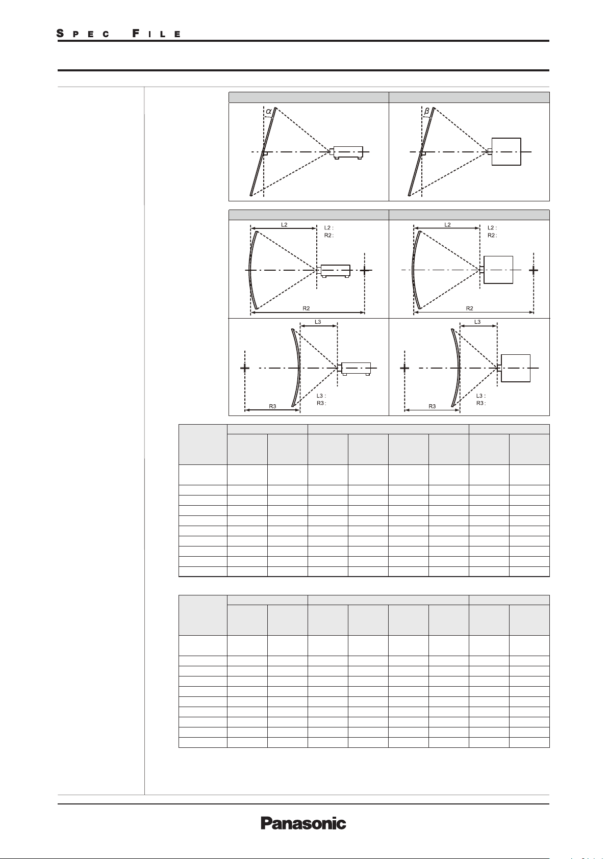
Geometry correction
range
[VERTICAL KEYSTONE] (viewed from the side) [HORIZONTAL KEYSTONE] (viewed from above)
Screen
Arc center
Screen
Screen
Projection distance
Arc radius
Screen
Vertical arc correction (viewed from the side) Horizontal arc correction (viewed from above)
Projection distance
Arc radius
Screen
Arc center
Screen
Projection distance
Arc radius
Projection
lens Model
No.
Supplied lens/
ET-DLE170
ET-DLE035*
ET-DLE055
ET-DLE060
ET-DLE085
ET-DLE105
ET-DLE150
ET-DLE250
ET-DLE350
ET-DLE450
Only [KEYSTONE] used
Vertical
keystone
correction
angle α (°)
±40
6
+5/-0
±22
±16
±22
±22
±40
±40
±40
±40
Horizontal
keystone
correction
angle β (°)
±15
0
±15
±10
±15
±15
±15
±15
±15
±15
When using the optional Upgrade Kit (Model No.: ET-UK20)
Projection
lens Model
No.
Supplied lens/
ET-DLE170
ET-DLE035*
ET-DLE055
ET-DLE060
ET-DLE085
ET-DLE105
ET-DLE150
ET-DLE250
ET-DLE350
ET-DLE450
Only [KEYSTONE] used
Vertical
keystone
correction
angle α (°)
±40
6
+5/-0
±22
±16
±22
±22
±40
±40
±45
±45
Horizontal
keystone
correction
angle β (°)
±40
0
±15
±10
±15
±15
±40
±40
±40
±40
*
[KEYSTONE] and [CURVED] used together Only [CURVED] used
7
Vertical
keystone
correction
angle α (°)
±20
±20
±20
±20
±20
Vertical
keystone
correction
angle α (°)
±20
±20
±20
±20
±20
Horizontal
keystone
correction
angle β (°)
±15
―
±8
―
±8
±8
―
±8
―
±8
±8
±15
±15
±15
±15
[KEYSTONE] and [CURVED] used together Only [CURVED] used
Horizontal
keystone
correction
angle β (°)
±15
―
±8
―
±8
±8
―
±8
―
±8
±8
±15
±15
±15
±15
Min. value
of R2/L2
0.9
―
1.7
―
1.7
1.7
1.1
0.7
0.4
0.3
Min. value
of R2/L2
0.7
―
1.3
―
1.3
1.3
0.9
0.5
0.3
0.2
Min. value
of R3/L3
1.7
―
4.3
―
4.3
4.3
2.6
1.3
0.8
0.6
Min. value
of R3/L3
1.3
―
3.3
―
3.3
3.3
2
1
0.6
0.4
Projection distance
Arc radius
Min. value
of R2/L2
0.5
―
1
―
1
1
0.6
0.4
0.3
0.2
Min. value
of R2/L2
0.4
―
0.8
―
0.8
0.8
0.5
0.3
0.2
0.2
Min. value
of R3/L3
1
―
2.6
―
2.6
2.6
1.5
0.7
0.5
0.3
Min. value
of R3/L3
0.7
―
1.9
―
1.9
1.9
1.1
0.6
0.4
0.3
As of May 2018
As of October 2018 2/22
RZ120G_SYF_01_17/10/2018
SFD16M034-3
3/21
Page 3
DLP™ Projector
PT-RZ120B/RZ120LB/RZ120W/RZ120LW
Optical axis shift
Vertical: +50%, -16%(powered)
(When using the ET-DLE060, +40%, -16%)
Horizontal: +30%, -10%(powered)
(When using the ET-DLE060, +19%, -10%)
(When using the ET-DLE085/ET-DLE105, +28%, -10%)
NOTE: Optical axis shift function cannot be operated when used with the ET-DLE055.
If using the ET-DLE035, the optical axis is fixed.
Installation Ceiling/floor, front/rear
Terminals SDI IN
HDMI IN
DVI-D IN
RGB 1 IN
R, G, B
Y, P
B, PR (Y, CB , CR
RGB 2 IN
R, G, B
Y, P
B, PR(Y, CB, CR)
SERIAL/MULTI PROJECTOR
SYNC IN
SERIAL/MULTI PROJECTOR
SYNC OUT
REMOTE 1 IN
REMOTE 1 OUT
REMOTE 2 IN D-sub 9-pin (female) ×1 for external control (parallel)
DIGITAL LINK/LAN
LAN RJ-45 × 1 for network connection, PJLink (class 2) compatible,
Power cord length
Cabinet materials
Dimensions
PT-RZ120B/RZ120W
(W × H × D)
PT-RZ120LB/RZ120LW
W
eight PT-RZ120B/RZ120W
PT-RZ120LB/RZ120LW
Operation noise
Laser
Laser Class
Classification
Risk Group
Operating temperature
Operating humidity
BNC × 1,
3G-SDI signal: SMPTE ST 424, 425-2 compliant
HD-SDI signal: SMPTE ST 292 compliant
SD-SDI signal: SMPTE ST 259 compliant
HDMI 19-pin × 1, Deep Color, compatible with HDCP2.2, 4K signal
DVI-D 24-pin × 1, DVI 1.0 compliant, compatible with HDCP,
for single link only
BNC ×5
R: 0.7 Vp-p, 75 ohms,
G: 0.7 Vp-p (G: 1.0 Vp-p for sync on G), 75 ohms,
B: 0.7 Vp-p, 75 ohms
HD, VD/SYNC: TTL, high impedance, positive/negative automatic
Y: 1.0 Vp-p (including sync signal), P
)
D-sub
HD 15-pin (female) ×1
B/PR (CB/CR): 0.7 Vp-p, 75 ohms
R: 0.7 Vp-p, 75 ohms,
G: 0.7 Vp-p (G: 1.0 Vp-p for sync on G), 75 ohms,
B: 0.7 Vp-p, 75 ohms
HD, VD/SYNC: TTL, high impedance, positive/negative automatic
Y: 1.0 Vp-p (including sync signal), P
B/PR(CB/CR): 0.7 Vp-p, 75 ohms
D-sub 9-pin (female) ×1 for external control (RS-232C compliant)
D-sub 9-pin (male) × 1 for link control
M3 jack × 1 for wired remote control
M3 jack × 1 for link control (for wired remote control)
RJ-45 × 1 for network and DIGITAL LINK (video/network/serial control)
(HDBaseT™ compliant), PJLink (class 2)compatible, 100Base-TX,
Art-Net compatible, HDCP 2.2 compatible, Deep Color compatible,
4K signal compatible
10Base-T/100Base-TX, Art-Net compatible
3.0 m (9 ft 10 in)
Molded plastic
8
498 x 200*
(19-19/32 x 7-7/8*
498 x 200*
(19-19/32 x 7-7/8*
x 581mm
8
x 22-7/8in ) with supplied lens
8
x 538 mm
8
x 21-3/16in) without lens
Approx. 23.6 kg (51.9 lbs.) with supplied lens
Approx. 22.8 kg (50.2 lbs.) without lens
44 dB[NORMAL] /41 dB[QUIET1] / 38dB[QUIET2])
USA and Canada: Class 3R (IEC 60825-1:2007)
Other countries or regions: Class 1 (IEC/EN 60825-1:2014)
Standard zoom lens, ET-DLE170,
ET-DLE035, ET-DLE055, ET-DLE060,
Risk Group 2 (IEC 62471-5:2015)
ET-DLE085, ET-DLE105, ET-DLE150
ET-DLE250, ET-DLE350, ET-DLE450 Risk Group 3 (IEC 62471-5:2015)
0–45 °C (32–113 °F)*
9
10%–80% (no condensation)
As of October 2018 3/22
RZ120G_SYF_01_17/10/2018
4/21
Page 4
PT-RZ120B/RZ120LB/RZ120W/RZ120LW
DLP™ Projector
DLP™ Projector
PT-RZ970B/RZ970W/RZ970LB/RZ970LW
Remote control unit
Power supply
Operation range
3 V DC (AAA/R03/LR03 battery × 2)
Approx. 30 m (98 ft 5 in) when operated from directly in front of the
signal receptor
Dimensions (W × H × D)
10
Weight*
48 × 145 × 27 mm (1-7/8 × 5-23/32 × 1-1/16 in)
Approx. 102 g (3.6 ozs.) including batteries
Other Applications
Multi Monitoring and Control Software (for Windows)
Logo Transfer Software (for Windows)
Geometry Manager Pro (for Windows)
Smart Projector Control (iOS/Android)
Supplied
accessories
Power cord with secure lock (× 1) (× 2 for Europe / ASIA models)
Wireless/wired remote control unit (× 1)
Batteries for remote control (AAA/R03 or AAA/LR03 battery x 2)
CD-ROM (Operating Instructions) (× 1)
Lens Mount Cover (× 1)
Lens cover (× 1) (Only models with lens)
Optional accessories
Digital interface box
ET-YFB100G
Digital LINK Switcher ET-YFB200G
Zoom lens ࠉ
Zoom
lens ET-DLE085
ET-DLE060
Zoom lens ET-DLE105
Zoom
lens
Zoom lens
Zoom lens
Zoom lens
Zoom lens
Fixed-focus lens
Fixed-focus lens
Ceiling mount bracket
ET-DLE150
ET-DLE170 (same as supplied lens)
ET-DLE250
ET-DLE350
ET-DLE450
ET-DLE035
ET-DLE055
ET-PKD120H (for high ceilings)
ET-PKD120S (for low ceilings)
High-ceiling mount bracket
ET-PKD130H
(6-axis adjustment mechanism)
Attachment for ceiling mount bracket
Geometry Manager Pro Upgrade kit
Auto Screen Adjustment Upgrade kit
ET-PKD130B
ET
-UK20
ET-CUK10/CUK10P
Early Warning Software ET-SWA100*
11
*1 Value is for the supplied standard zoom lens. The value varies depending on the lens.
*2 Measurement, measuring conditions, and method of notation all comply with ISO/IEC 21118:2012 international standards.
*3 Average light-output value of all shipped products measured at center of screen in NORMAL Mode.
*4 Around this time, light output will have decreased by approximately 50 %. IEC62087: 2008 Broadcast contents, NORMAL Mode, Dynamic Contrast [3],
under conditions with 30 °C (86 °F), 700 m (2,297 ft) above sea level, and 0.15 mg/m3 of particulate matter. Estimated time until light output declines to 50 % varies
depending on environment.
*5 Only the vertical keystone correction angle can be corrected in the direction in which the projector body moves
away from the screen.
*6 When [VERTICAL KEYSTONE] and [HORIZONTAL KEYSTONE] are used simultaneously, correction cannot be
made exceeding total of 55°.
• When [GEOMETRY] is used, the focus of the entire screen may be lost as correction increases.
• Make the curved screen a circular arc shape with one part of a perfect circle removed.
• Adjustment range of the [GEOMETRY] items may not match the listed projection range depending on the
projection lens. Use this projector within the projection range, otherwise the correction may not work.
*7 Only compatible with dot clock frequency of 27 MHz (pixel repetition signal).
*8 with legs at shortest position.
*9 Limits the luminance when used in locations from 0m to 2,700m (0ft to 8,858ft) above sea level at ambient temperatures of 30°C (86°F) or higher,
or from 2,700m to 4,200m (8,858ft to 13,780ft) above sea level at ambient temperatures of 25°C (77°F) or higher.
*10 Average value. Weight varies for each product.
*11 The symbol at the end of the part number will vary depending on the type of license.
As of May 2018
As of October 2018 4/22
RZ120G_SYF_01_17/10/2018
SFD16M034-3
5/21
Page 5
DLP™ Projector
DLP™ Projector
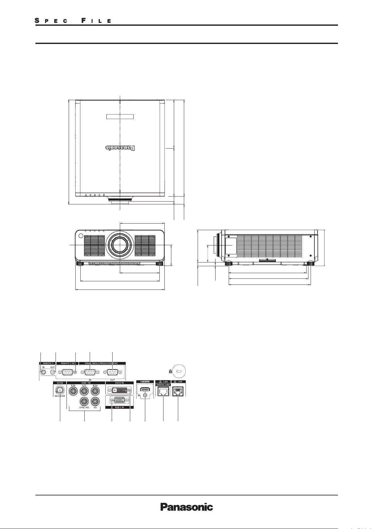
Dimensions
580.8
(22-7/8)
PT-RZ120B/RZ120LB/RZ120W/RZ120LW
PT-RZ970B/RZ970W/RZ970LB/RZ970LW
(10-19/32)(10-19/32)
538
(21-3/16)
Terminals
1
2345
67 8910 11 12
249 (9-13/16)
221 (8-11/16)
442 (17-13/32)
498 (19-19/32)
269 269
28
115.5
(4-9/16)
unit : mm (inch)
NOTE: This illustration is not drawn to scale.
42.8
(1-3/32)
(1-11/16)
180
(7-3/32)
95.5
(3-3/4)
432 (17)
444 (15/32)
457 (18)
20
(25/32)
4
(5/32)
1 REMOTE 1 INPUT
2 REMOTE 1 OUTPUT
3 REMOTE 2 INPUT
4 SERIAL/MULTI PROJECTOR SYNC INPUT
5 SERIAL/MULTI PROJECTOR SYNC OUTPUT
6 SDI INPUT
7 RGB 1 INPUT
8 RGB 2 INPUT
9 DVI-D INPUT
10 HDMI INPUT
11 DIGITAL LINK/LAN
12 LAN
200
(7-7/8)
As of May 2018
As of October 2018 5/22
RZ120G_SYF_01_17/10/2018
SFD16M034-3
6/21
Page 6
PT-RZ120B/RZ120LB/RZ120W/RZ120LW
DLP™ Projector
DLP™ Projector
PT-RZ970B/RZ970W/RZ970LB/RZ970LW
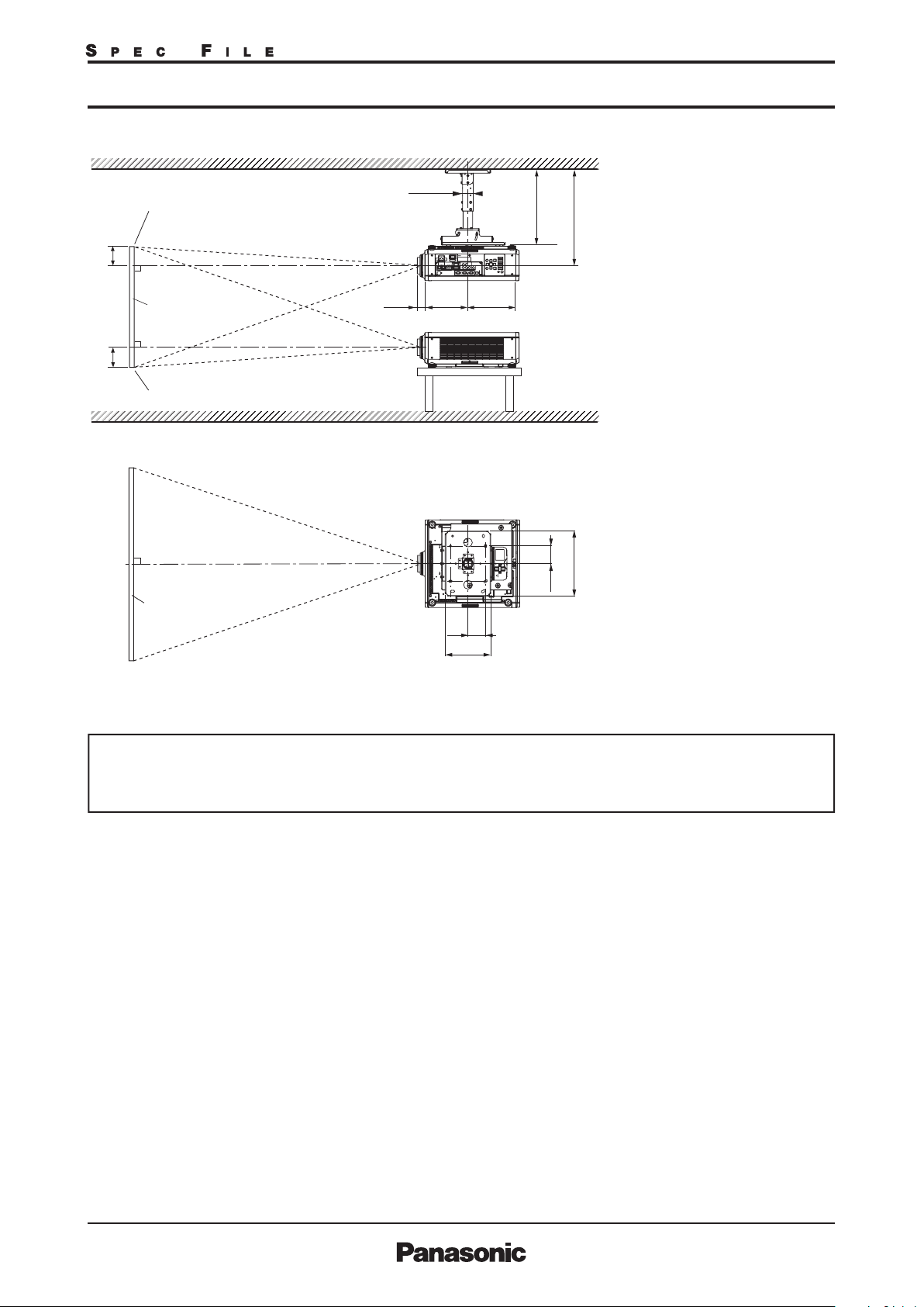
Standard setting-up position (If using other than the ET-DLE035)
2
*
352–432
(13-27/32–17)
294244
Upper edge of projected image
EE
ø60.5
L
1
*
(11-9/16)(9-19/32)
*1 When the lens protrudes to the maximum.
2
463.5–543.5*
104 mm (4-3/32 in) with the ET-DLE060
84 mm (3-5/16 in) with the ET-DLE085
88 mm (3-15/32 in) with the ET-DLE105
44 mm (1-23/32 in) with the ET-DLE150
43 mm (1-11/16 in)
with the supplied lens/ET-DLE170
45 mm (1-25/32 in) with the ET-DLE250
51mm (2 in) with the ET-DLE350
95 mm (3-3/4 in) with the ET-DLE450
(18-1/4–21-13/32)
27 mm (1-1/16 in) with the ET-DLE055
*2 Adjustable in 40 mm (1-9/16 in) steps.
Lower edge of projected image
Projected image
100
(3-15/16)
259
(10-3/16)
100
(3-15/16)
370
(14-9/16)
NOTE:
Illustrations show the projector
installed using optional ceiling mount
bracket ET-PKD120H, optional bracket
assembly ET-PKD130B and an optional
lens.
This illustration is not drawn to scale.
unit : mm (inch)
Caution:
• All construction work should be done by a qualified technician.
• When mounting to the ceiling, use the special mounting bracket. Furthermore, in order to prevent it from falling
down from the ceiling, use the supplied wire on the mounting bracket.
As of May 2018
As of October 2018 6/22
RZ120G_SYF_01_17/10/2018
SFD16M034-3
7/21
Page 7
DLP™ Projector
DLP™ Projector
PT-RZ120B/RZ120LB/RZ120W/RZ120LW
PT-RZ970B/RZ970W/RZ970LB/RZ970LW
Projection distance for 16:10 aspect ratio screen (If using other than the ET-DLE035)
Distance to screen (L)
9.12
11.01
12.89
14.78
16.66
18.55
22.31
27.97
37.39
46.81
56.24
65.66
75.08
93.93
112.77
29.9
36.1
42.3
48.5
54.7
60.8
73.2
91.8
122.7
153.6
184.5
215.4
246.3
308.2
370.0
Fixed-focus
ET-DLE055
Fixed-
focus lens
0.786:1
0.83
1.00
1.18
1.35
1.53
1.70
2.05
2.58
3.45
−
−
−
−
−
−
Fixed-focus
ET-DLE055
Fixed-
focus lens
0.786:1
2.7
3.3
3.9
4.4
5.0
5.6
6.7
8.5
11.3
−
−
−
−
−
−
Screen
size
(diagonal)
ET-DLE060
Zoom lens
ET-DLE085
Zoom lens
ET-DLE105
Zoom lens
ET-DLE150
Zoom lens
Zoom
Supplied lens
ET-DLE170
Zoom lens
ET-DLE250
Zoom lens
ET-DLE350
Zoom lens
ET-DLE450
Zoom lens
Throw ratio
0.600-0.801:1 0.782-0.977:1 0.978-1.32:1 01.30-1.89:1 1.71-2.41:1 2.27-3.62:1 3.58-5.45:1 5.36-8.58:1
[m][in]
1.27
1.52
1.78
2.03
2.29
2.54
3.05
3.81
5.08
6.35
7.62
8.89
10.16
12.70
15.24
0.84
0.63
50
/
1.02
0.76
60
/
1.20
0.90
70
/
1.38
1.03
80
/
1.56
1.17
90
/
1.74
1.31
100
/
2.10
1.58
120
/
2.63
1.99
150
/
3.53
2.67
200
/
4.42
3.35
250
/
5.32
4.03
300
/
6.21
4.71
350
/
7.11
5.39
400
/
8.90
6.75
500
/
10.69
8.11
600
/
0.82
1.00
1.17
1.35
1.52
1.70
2.05
2.57
3.44
4.31
5.18
6.06
6.93
8.67
10.42
1.04
1.25
1.47
1.68
1.90
2.11
2.55
3.19
4.27
5.35
6.43
7.51
8.59
10.75
12.91
1.03
1.25
1.47
1.68
1.90
2.12
2.55
3.20
4.29
5.37
6.46
7.54
8.63
10.80
12.97
min. max.min. max.min. max.min. max. min. max.min. max.min. max.
1.38
1.41
1.66
1.70
1.95
1.99
2.23
2.28
2.52
2.57
2.81
2.86
3.38
3.44
4.24
4.32
5.67
5.77
7.10
7.23
8.53
8.68
9.96
10.14
11.39
11.59
14.25
14.50
17.11
17.41
2.01
2.43
2.84
3.25
3.66
4.08
4.90
6.14
8.20
10.26
12.33
14.39
16.45
20.58
24.70
min. max.
1.82
2.20
2.58
2.95
3.33
3.71
4.47
5.60
10.50
7.50
13.14
9.39
15.79
11.28
18.43
13.18
21.07
15.07
26.36
18.86
31.65
22.64
2.57
3.10
3.63
4.16
4.69
5.21
6.27
7.86
2.42
2.92
3.42
3.92
4.42
4.92
5.91
7.41
9.91
12.41
14.91
17.40
19.90
24.90
29.89
3.87
4.65
5.44
6.23
7.02
7.81
9.39
11.75
15.70
19.64
23.59
27.53
31.48
39.37
47.25
3.80
4.59
5.38
6.16
6.95
7.74
9.31
11.68
15.61
19.55
23.49
27.42
31.36
39.23
47.11
5.81
7.00
8.19
9.38
10.57
11.76
14.14
17.71
23.66
29.61
35.56
41.51
47.46
59.36
71.25
5.66
6.85
8.04
9.23
10.43
11.62
14.00
17.58
23.54
29.50
35.46
41.42
47.38
59.30
71.22
Distance to screen (L)
Screen
size
(diagonal)
ET-DLE060
Zoom lens
ET-DLE085
Zoom lens
ET-DLE105
Zoom lens
ET-DLE150
Zoom lens
Zoom
Supplied lens
ET-DLE170
Zoom lens
ET-DLE250
Zoom lens
ET-DLE350
Zoom lens
ET-DLE450
Zoom lens
Throw ratio
0.600-0.801:1 0.782-0.977:1 0.978-1.32:1 01.30-1.89:1 1.71-2.41:1 2.27-3.62:1 3.58-5.45:1 5.36-8.58:1
[m][in]
2.8
1.27
1.52
1.78
2.03
2.29
2.54
3.05
3.81
5.08
6.35
7.62
8.89
10.16
12.70
15.24
•The value for L (distance to screen) varies slightly within ±5% depending on the zoom lens characteristics.
•The zoom lens characteristics may cause slight image distortion.
•When using keystone correction is used, the image is corrected in the direction that reduces its projected size.
•The brightness varies depending on the zoom setting.
Note: When the ET-DLE055 is mounted, the optical lens shift function cannot be used.
2.1
50
/
3.4
2.5
60
/
3.9
2.9
70
/
4.5
3.4
80
/
5.1
3.8
90
/
5.7
4.3
100
/
6.9
5.2
120
/
8.6
6.5
150
/
11.6
8.7
200
/
14.5
11.0
250
/
17.4
13.2
300
/
20.4
15.4
350
/
23.3
17.7
400
/
29.2
22.1
500
/
35.1
26.6
600
/
2.7
3.3
3.9
4.4
5.0
5.6
6.7
8.4
11.3
14.1
17.0
19.9
22.7
28.5
34.2
3.4
4.1
4.8
5.5
6.2
6.9
8.4
10.5
14.0
17.6
21.1
24.6
28.2
35.3
42.3
3.4
4.1
4.8
5.5
6.2
7.0
8.4
10.5
14.1
17.6
21.2
24.8
28.3
35.4
42.5
min. max.min. max.min. max.min. max. min. max.min. max.min. max.
4.5
4.6
5.5
5.6
6.4
6.5
7.3
7.5
8.3
8.4
9.2
9.4
11.1
11.3
13.9
14.2
18.6
18.9
23.3
23.7
28.0
28.5
32.7
33.3
37.4
38.0
46.7
47.6
56.1
57.1
6.6
8.0
9.3
10.7
12.0
13.4
16.1
20.1
26.9
33.7
40.4
47.2
54.0
67.5
81.1
min. max.
6.0
10.2
7.2
11.9
8.5
13.6
9.7
15.4
10.9
17.1
12.2
20.6
14.7
25.8
18.4
34.5
24.6
43.1
30.8
51.8
37.0
60.5
43.2
69.1
49.4
86.5
61.9
103.8
74.3
8.4
7.9
9.6
11.2
12.8
14.5
16.1
19.4
24.3
32.5
40.7
48.9
57.1
65.3
81.7
98.1
12.7
15.3
17.9
20.4
23.0
25.6
30.8
38.6
51.5
64.4
77.4
90.3
103.3
129.2
155.0
12.5
15.1
17.6
20.2
22.8
25.4
30.6
38.3
51.2
64.1
77.1
90.0
102.9
128.7
154.6
19.1
23.0
26.9
30.8
34.7
38.6
46.4
58.1
77.6
97.1
116.7
136.2
155.7
194.7
233.8
18.6
22.5
26.4
30.3
34.2
38.1
45.9
57.7
77.2
96.8
116.3
135.9
155.4
194.6
233.7
Unit: meters
Height from the edge of
screen to center of lens
(H)
㻿㼡㼜㼜㼘㼕㼑㼐㻌㼘㼑㼚㼟
㻱㼀㻙㻰㻸㻱㻜㻤㻡
㻝㻜㻡㻛㻝㻡㻜㻛㻞㻡㻜
㻟㻡㻜㻛㻠㻡㻜
0
–
0
–
0
–
0
–
0
–
0
–
0
–
0
–
0
–
0
–
0
–
0
–
0
–
0
–
0
–
0.44
0.53
0.62
0.71
0.80
0.89
1.07
1.33
1.78
2.22
2.67
3.11
3.55
4.44
5.33
㻱㼀㻙
㻰㻸㻱㻜㻢㻜
0.07
0.08
0.09
0.11
0.12
0.13
0.16
0.20
0.27
0.34
0.40
0.47
0.54
0.67
0.81
0.44
–
0.53
–
0.62
–
0.71
–
0.80
–
0.89
–
1.07
–
1.33
–
1.78
–
2.22
–
2.67
–
3.11
–
3.55
–
4.44
–
5.33
–
Unit: feet
Height from the edge of
screen to center of lens
(H)
㻿㼡㼜㼜㼘㼕㼑㼐㻌㼘㼑㼚㼟
㻱㼀㻙㻰㻸㻱㻜㻤㻡
㻝㻜㻡㻛㻝㻡㻜㻛㻞㻡㻜
㻟㻡㻜㻛㻠㻡㻜
0
–
0
–
0
–
0
–
0
–
0
–
0
–
0
–
0
–
0
–
0
–
0
–
0
–
0
–
0
–
1.5
1.7
2.0
2.3
2.6
2.9
3.5
4.4
5.8
7.3
8.7
10.2
11.7
14.6
17.5
㻱㼀㻙
㻰㻸㻱㻜㻢㻜
0.2
–
0.3
–
0.3
–
0.4
–
0.4
–
0.4
–
0.5
–
0.7
–
0.9
–
1.1
–
1.3
–
1.5
–
1.8
–
2.2
–
2.6
–
1.5
1.7
2.0
2.3
2.6
2.9
3.5
4.4
5.8
7.3
8.7
10.2
11.7
14.6
17.5
㻱㼀㻙
㻰㻸㻱㻜㻡㻡
0.34
0.40
0.47
0.54
0.61
0.67
0.81
1.01
1.35
−
−
−
−
−
−
㻱㼀㻙
㻰㻸㻱㻜㻡㻡
1.1
1.3
1.5
1.8
2.0
2.2
2.6
3.3
4.4
−
−
−
−
−
−
As of May 2018
As of October 2018 7/22
RZ120G_SYF_01_17/10/2018
SFD16M034-3
8/21
Page 8

DLP™ Projector
DLP™ Projector
PT-RZ120B/RZ120LB/RZ120W/RZ120LW
PT-RZ970B/RZ970W/RZ970LB/RZ970LW
Projection distance for 16:9 aspect ratio screen (If using other than the ET-DLE035)
Distance to screen (L)
9.39
11.32
13.26
15.20
17.13
19.07
22.94
28.75
38.44
48.12
57.81
67.49
77.18
96.55
115.91
30.8
37.1
43.5
49.9
56.2
62.6
75.3
94.3
126.1
157.9
189.7
221.4
253.2
316.8
380.3
Fixed-focus
ET-DLE055
Fixed-
focus lens
0.786:1
0.85
1.03
1.21
1.39
1.57
1.75
2.11
2.65
3.55
−
−
−
−
−
−
Fixed-focus
ET-DLE055
Fixed-
focus lens
0.786:1
2.8
3.4
4.0
4.6
5.2
5.7
6.9
8.7
11.7
−
−
−
−
−
−
Screen
size
(diagonal)
ET-DLE060
Zoom lens
ET-DLE085
Zoom lens
ET-DLE105
Zoom lens
ET-DLE150
Zoom lens
Zoom
Supplied lens
ET-DLE170
Zoom lens
ET-DLE250
Zoom lens
ET-DLE350
Zoom lens
ET-DLE450
Zoom lens
Throw ratio
0.600-0.802:1 0.783-0.977:1 0.979-1.32:1 1.30-1.89:1 1.72-2.41:1 2.27-3.62:1 3.58-5.45:1 5.36-8.58:1
[m][in]
1.27
1.52
1.78
2.03
2.29
2.54
3.05
3.81
5.08
6.35
7.62
8.89
10.16
12.70
15.24
0.87
0.64
50
/
1.05
0.78
60
/
1.24
0.92
70
/
1.42
1.06
80
/
1.60
1.20
90
/
1.79
1.34
100
/
2.16
1.62
120
/
2.71
2.04
150
/
3.63
2.74
200
/
4.55
3.44
250
/
5.47
4.14
300
/
6.39
4.84
350
/
7.31
5.54
400
/
9.15
6.93
500
/
10.99
8.33
600
/
0.85
1.03
1.21
1.39
1.57
1.75
2.10
2.64
3.54
4.43
5.33
6.23
7.12
8.91
10.71
1.07
1.29
1.51
1.73
1.95
2.17
2.62
3.28
4.39
5.50
6.61
7.72
8.83
11.05
13.27
1.06
1.29
1.51
1.73
1.96
2.18
2.63
3.29
4.41
5.52
6.64
7.76
8.87
11.10
13.33
min. max.min. max.min. max.min. max. min. max.min. max.min. max.
1.42
1.45
1.71
1.75
2.00
2.05
2.30
2.35
2.59
2.64
2.89
2.94
3.47
3.54
4.36
4.44
5.82
5.93
7.29
7.43
8.76
8.93
10.23
10.42
11.70
11.92
14.64
14.91
17.58
17.90
2.07
2.49
2.92
3.34
3.77
4.19
5.04
6.31
8.43
10.55
12.67
14.79
16.91
21.15
25.39
min. max.
1.87
2.26
2.65
3.04
3.43
3.82
4.60
5.76
7.71
9.65
11.60
13.55
15.49
19.38
23.27
10.80
13.51
16.23
18.95
21.66
27.10
32.53
2.64
3.19
3.73
4.27
4.82
5.36
6.45
8.08
2.49
3.00
3.51
4.03
4.54
5.05
6.08
7.62
10.19
12.75
15.32
17.89
20.46
25.59
30.72
3.97
4.79
5.60
6.41
7.22
8.03
9.65
12.08
16.14
20.19
24.25
28.30
32.35
40.46
48.57
3.91
4.72
5.53
6.34
7.15
7.96
9.58
12.00
16.05
20.10
24.14
28.19
32.24
40.33
48.42
5.98
7.20
8.43
9.65
10.87
12.09
14.54
18.21
24.32
30.44
36.55
42.67
48.78
61.01
73.24
5.82
7.05
8.27
9.50
10.72
11.95
14.40
18.08
24.20
30.33
36.45
42.58
48.71
60.96
73.21
Distance to screen (L)
Screen
size
(diagonal)
ET-DLE060
Zoom len
s
ET-DLE085
Zoom lens
ET-DLE105
Zoom lens
ET-DLE150
Zoom lens
Zoom
Supplied lens
ET-DLE170
Zoom lens
ET-DLE250
Zoom lens
ET-DLE350
Zoom lens
ET-DLE450
Zoom lens
Throw ratio
0.600-0.802:1 0.783-0.977:1 0.979-1.32:1 1.30-1.89:1 1.72-2.41:1 2.27-3.62:1 3.58-5.45:1 5.36-8.58:1
[m][in]
2.8
1.27
1.52
1.78
2.03
2.29
2.54
3.05
3.81
5.08
6.35
7.62
8.89
10.16
12.70
15.24
• The value for L (distance to screen) varies slightly within ±5% depending on the zoom lens characteristics.
• The zoom lens characteristics may cause slight image distortion.
• When using keystone correction is used, the image is corrected in the direction that reduces its projected size.
• The brightness varies depending on the zoom setting.
Note: When the ET-DLE055 is mounted, the optical lens shift function cannot be used.
2.1
50
/
3.5
2.6
60
/
4.1
3.0
70
/
4.7
3.5
80
/
5.3
3.9
90
/
5.9
4.4
100
/
7.1
5.3
120
/
8.9
6.7
150
/
11.9
9.0
200
/
14.9
11.3
250
/
17.9
13.6
300
/
21.0
15.9
350
/
24.0
18.2
400
/
30.0
22.7
500
/
36.0
27.3
600
/
2.8
3.4
4.0
4.5
5.1
5.7
6.9
8.7
11.6
14.5
17.5
20.4
23.4
29.2
35.1
3.5
4.2
5.0
5.7
6.4
7.1
8.6
10.8
14.4
18.1
21.7
25.3
29.0
36.2
43.5
3.5
4.2
5.0
5.7
6.4
7.2
8.6
10.8
14.5
18.1
21.8
25.5
29.1
36.4
43.7
min. max.min. max.min. max.min. max. min. max.min. max.min. max.
4.6
4.8
5.6
5.7
6.6
6.7
7.5
7.7
8.5
8.7
9.5
9.6
11.4
11.6
14.3
14.6
19.1
19.5
23.9
24.4
28.8
29.3
33.6
34.2
38.4
39.1
48.0
48.9
57.7
58.7
6.8
8.2
9.6
11.0
12.4
13.7
16.5
20.7
27.7
34.6
41.6
48.5
55.5
69.4
83.3
min. max.
6.1
10.5
7.4
12.2
8.7
14.0
10.0
15.8
11.2
17.6
12.5
21.2
15.1
26.5
18.9
35.4
25.3
44.3
31.7
53.2
38.1
62.2
44.4
71.1
50.8
88.9
63.6
106.7
76.4
8.7
8.2
9.8
11.5
13.2
14.9
16.6
19.9
25.0
33.4
41.8
50.3
58.7
67.1
84.0
100.8
13.0
15.7
18.4
21.0
23.7
26.3
31.7
39.6
52.9
66.2
79.5
92.8
106.1
132.8
159.4
12.8
15.5
18.1
20.8
23.5
26.1
31.4
39.4
52.7
65.9
79.2
92.5
105.8
132.3
158.9
19.6
23.6
27.6
31.7
35.7
39.7
47.7
59.7
79.8
99.9
119.9
140.0
160.0
200.2
240.3
19.1
23.1
27.1
31.2
35.2
39.2
47.2
59.3
79.4
99.5
119.6
139.7
159.8
200.0
240.2
Unit: meters
Height from the edge of
screen to center of lens
(H)
㻿㼡㼜㼜㼘㼕㼑㼐㻌㼘㼑㼚㼟
㻱㼀㻙㻰㻸㻱㻜㻤㻡
㻝㻜㻡㻛㻝㻡㻜㻛㻞㻡㻜
㻟㻡㻜㻛㻠㻡㻜
-0.06
–
-0.07
–
-0.09
–
-0.10
–
-0.11
–
-0.12
–
-0.15
–
-0.19
–
-0.25
–
-0.31
–
-0.37
–
-0.44
–
-0.50
–
-0.62
–
-0.75
–
0.46
0.55
0.64
0.73
0.82
0.91
1.10
1.37
1.83
2.28
2.74
3.20
3.65
4.57
5.48
㻱㼀㻙
㻰㻸㻱㻜㻢㻜
0.46
0
–
0.55
0
–
0.64
0
–
0.73
0
–
0.82
0
–
0.91
0
–
1.10
0
–
1.37
0
–
1.83
0
–
2.28
0
–
2.74
0
–
3.20
0
–
3.65
0
–
4.57
0
–
5.48
0
–
Height from the edge of
screen to center of lens
(H)
㻿㼡㼜㼜㼘㼕㼑㼐㻌㼘㼑㼚㼟
㻱㼀㻙㻰㻸㻱㻜㻤㻡
㻝㻜㻡㻛㻝㻡㻜㻛㻞㻡㻜
㻟㻡㻜㻛㻠㻡㻜
-0.2
–
-0.2
–
-0.3
–
-0.3
–
-0.4
–
-0.4
–
-0.5
–
-0.6
–
-0.8
–
-1.0
–
-1.2
–
-1.4
–
-1.6
–
-2.0
–
-2.5
–
1.5
1.8
2.1
2.4
2.7
3.0
3.6
4.5
6.0
7.5
9.0
10.5
12.0
15.0
18.0
㻱㼀㻙
㻰㻸㻱㻜㻢㻜
1.5
0
–
1.8
0
–
2.1
0
–
2.4
0
–
2.7
0
–
3.0
0
–
3.6
0
–
4.5
0
–
6.0
0
–
7.5
0
–
9.0
0
–
10.5
0
–
12.0
0
–
15.0
0
–
18.0
0
–
㻱㼀㻙
㻰㻸㻱㻜㻡㻡
0.31
0.37
0.44
0.50
0.56
0.62
0.75
0.93
1.25
−
−
−
−
−
−
Unit: feet
㻱㼀㻙
㻰㻸㻱㻜㻡㻡
1.0
1.2
1.4
1.6
1.8
2.0
2.5
3.1
4.1
−
−
−
−
−
−
As of May 2018
As of October 2018 8/22
SFD16M034-3
RZ120G_SYF_01_17/10/2018
9/21
Page 9

DLP™ Projector
DLP™ Projector
PT-RZ120B/RZ120LB/RZ120W/RZ120LW
PT-RZ970B/RZ970W/RZ970LB/RZ970LW
Projection distance for 4:3 aspect ratio screen (If using other than the ET-DLE035)
Distance to screen (L)
10.37
12.50
14.63
16.77
18.90
21.03
25.30
31.70
42.37
53.04
63.70
74.37
85.04
106.37
127.70
34.0
41.0
48.0
55.0
62.0
69.0
83.0
104.0
139.0
174.0
209.0
244.0
279.0
349.0
419.0
Fixed-focus
ET-DLE055
Fixed-
focus lens
0.946:1
0.94
1.14
1.34
1.54
1.74
1.93
2.33
2.93
3.92
−
−
−
−
−
−
Fixed-focus
ET-DLE055
Fixed-
focus lens
0.946:1
3.1
3.7
4.4
5.0
5.7
6.3
7.6
9.6
12.8
−
−
−
−
−
−
Screen
size
(diagonal)
ET-DLE060
Zoom lens
ET-DLE085
Zoom lens
ET-DLE105
Zoom lens
ET-DLE150
Zoom lens
Zoom
Supplied lens
ET-DLE170
Zoom lens
ET-DLE250
Zoom lens
ET-DLE350
Zoom lens
ET-DLE450
Zoom lens
Throw ratio
0.724-0.965:1 0.943-1.18:1 1.18-1.59:1 1.56-2.27:1 2.06-2.90:1 2.73-4.35:1 4.30-6.55:1 6.46-10.3:1
[m][in]
1.27
1.52
1.78
2.03
2.29
2.54
3.05
3.81
5.08
6.35
7.62
8.89
10.16
12.70
15.24
0.96
0.71
50
/
1.16
0.87
60
/
1.37
1.02
70
/
1.57
1.18
80
/
1.77
1.33
90
/
1.97
1.48
100
/
2.38
1.79
120
/
2.99
2.25
150
/
4.00
3.02
200
/
5.01
3.79
250
/
6.03
4.56
300
/
7.04
5.33
350
/
8.05
6.10
400
/
10.08
7.64
500
/
12.11
9.18
600
/
0.94
1.14
1.33
1.53
1.73
1.93
2.32
2.91
3.90
4.89
5.88
6.86
7.85
9.82
11.80
1.18
1.42
1.67
1.91
2.16
2.40
2.89
3.62
4.84
6.07
7.29
8.51
9.73
12.17
14.62
1.18
1.42
1.67
1.91
2.16
2.41
2.90
3.63
4.86
6.09
7.32
8.55
9.78
12.23
14.69
min. max.min. max.min. max.min. max. min. max.min. max.min. max.
1.56
1.60
1.89
1.93
2.21
2.26
2.54
2.59
2.86
2.92
3.18
3.25
3.83
3.91
4.80
4.89
6.42
6.54
8.04
8.19
9.66
9.84
11.28
11.48
12.90
13.13
16.13
16.42
19.37
19.72
2.29
2.75
3.22
3.69
4.15
4.62
5.55
6.96
9.29
11.63
13.96
16.30
18.63
23.30
27.97
min. max.
2.07
2.50
2.93
3.35
3.78
4.21
5.07
6.35
8.50
10.64
12.78
14.93
17.07
21.36
25.64
11.90
14.89
17.88
20.88
23.87
29.85
35.84
2.92
3.52
4.12
4.72
5.31
5.91
7.11
8.91
2.75
3.31
3.88
4.44
5.01
5.57
6.71
8.40
11.23
14.06
16.88
19.71
22.54
28.19
33.85
4.39
5.28
6.17
7.07
7.96
8.85
10.64
13.32
17.78
22.25
26.71
31.18
35.64
44.58
53.51
4.32
5.21
6.10
7.00
7.89
8.78
10.56
13.24
17.69
22.15
26.61
31.06
35.52
44.43
53.35
6.60
7.95
9.29
10.64
11.99
13.34
16.03
20.07
26.80
33.54
40.27
47.01
53.74
67.21
80.68
6.45
7.80
9.14
10.49
11.84
13.19
15.89
19.94
26.69
33.44
40.18
46.93
53.68
67.17
80.67
Distance to screen (L)
Screen
size
(diagonal)
ET-DLE060
Zoom lens
ET-DLE085
Zoom lens
ET-DLE105
Zoom lens
ET-DLE150
Zoom lens
Zoom
Supplied lens
ET-DLE170
Zoom lens
ET-DLE250
Zoom lens
ET-DLE350
Zoom lens
ET-DLE450
Zoom lens
Throw ratio
0.724-0.965:1 0.943-1.18:1 1.18-1.59:1 1.56-2.27:1 2.06-2.90:1 2.73-4.35:1 4.30-6.55:1 6.46-10.3:1
[m][in]
3.2
1.27
1.52
1.78
2.03
2.29
2.54
3.05
3.81
5.08
6.35
7.62
8.89
10.16
12.70
15.24
• The value for L (distance to screen) varies slightly within ±5% depending on the z oom lens characteristics.
• The zoom lens characteristics may cause slight image distortion.
• When using keystone correction is used, the image is corrected in the direction that reduces its projected size.
• The brightness varies depending on the zoom setting.
Note: When the ET-DLE055 is mounted, the optical lens shift function cannot be used.
2.3
50
/
3.8
2.9
60
/
4.5
3.4
70
/
5.1
3.9
80
/
5.8
4.4
90
/
6.5
4.9
100
/
7.8
5.9
120
/
9.8
7.4
150
/
13.1
9.9
200
/
16.5
12.4
250
/
19.8
15.0
300
/
23.1
17.5
350
/
26.4
20.0
400
/
33.1
25.1
500
/
39.7
30.1
600
/
3.1
3.7
4.4
5.0
5.7
6.3
7.6
9.6
12.8
16.0
19.3
22.5
25.8
32.2
38.7
3.9
4.7
5.5
6.3
7.1
7.9
9.5
11.9
15.9
19.9
23.9
27.9
31.9
39.9
48.0
3.9
4.7
5.5
6.3
7.1
7.9
9.5
11.9
16.0
20.0
24.0
28.0
32.1
40.1
48.2
min. max.min. max.min. max.min. max. min. max.min. max.min. max.
5.1
5.2
6.2
6.3
7.3
7.4
8.3
8.5
9.4
9.6
10.4
10.7
12.6
12.8
15.8
16.1
21.1
21.5
26.4
26.9
31.7
32.3
37.0
37.7
42.3
43.1
52.9
53.9
63.6
64.7
7.5
9.0
10.6
12.1
13.6
15.2
18.2
22.8
30.5
38.1
45.8
53.5
61.1
76.5
91.8
min. max.
6.8
11.5
8.2
13.5
9.6
15.5
11.0
17.4
12.4
19.4
13.8
23.3
16.6
29.2
20.8
39.0
27.9
48.9
34.9
58.7
41.9
68.5
49.0
78.3
56.0
97.9
70.1
117.6
84.1
9.6
9.0
10.9
12.7
14.6
16.4
18.3
22.0
27.6
36.8
46.1
55.4
64.7
73.9
92.5
111.1
14.4
17.3
20.3
23.2
26.1
29.0
34.9
43.7
58.3
73.0
87.6
102.3
116.9
146.2
175.5
14.2
17.1
20.0
23.0
25.9
28.8
34.7
43.4
58.0
72.7
87.3
101.9
116.5
145.8
175.0
21.7
26.1
30.5
34.9
39.3
43.8
52.6
65.8
87.9
110.0
132.1
154.2
176.3
220.5
264.7
21.1
25.6
30.0
34.4
38.9
43.3
52.1
65.4
87.6
109.7
131.8
154.0
176.1
220.4
264.7
Unit: meters
Height from the edge of
screen to center of lens
(H)
㻿㼡㼜㼜㼘㼕㼑㼐㻌㼘㼑㼚㼟
㻱㼀㻙㻰㻸㻱㻜㻤㻡
㻝㻜㻡㻛㻝㻡㻜㻛㻞㻡㻜
㻟㻡㻜㻛㻠㻡㻜
0
–
0
–
0
–
0
–
0
–
0
–
0
–
0
–
0
–
0
–
0
–
0
–
0
–
0
–
0
–
0.50
0.60
0.70
0.80
0.91
1.01
1.21
1.51
2.01
2.51
3.02
3.52
4.02
5.03
6.04
㻱㼀㻙
㻰㻸㻱㻜㻢㻜
0.08
0.09
0.11
0.12
0.14
0.15
0.18
0.23
0.30
0.38
0.46
0.53
0.61
0.76
0.91
0.50
–
0.60
–
0.70
–
0.80
–
0.91
–
1.01
–
1.21
–
1.51
–
2.01
–
2.51
–
3.02
–
3.52
–
4.02
–
5.03
–
6.04
–
Unit: feet
Height from the edge of
screen to center of lens
(H)
㻿㼡㼜㼜㼘㼕㼑㼐㻌㼘㼑㼚㼟
㻱㼀㻙㻰㻸㻱㻜㻤㻡
㻝㻜㻡㻛㻝㻡㻜㻛㻞㻡㻜
㻟㻡㻜㻛㻠㻡㻜
0
–
0
–
0
–
0
–
0
–
0
–
0
–
0
–
0
–
0
–
0
–
11.6
0
–
13.2
0
–
16.5
0
–
19.8
0
–
1.7
2.0
2.3
2.6
3.0
3.3
4.0
5.0
6.6
8.3
9.9
㻱㼀㻙
㻰㻸㻱㻜㻢㻜
0.3
–
0.3
–
0.4
–
0.4
–
0.5
–
0.5
–
0.6
–
0.8
–
1.0
–
1.3
–
1.5
–
1.8
–
2.0
–
2.5
–
3.0
–
1.7
2.0
2.3
2.6
3.0
3.3
4.0
5.0
6.6
8.3
9.9
11.6
13.2
16.5
19.8
㻱㼀㻙
㻰㻸㻱㻜㻡㻡
0.38
0.46
0.53
0.61
0.69
0.76
0.91
1.14
1.52
−
−
−
−
−
−
㻱㼀㻙
㻰㻸㻱㻜㻡㻡
1.3
1.5
1.8
2.0
2.3
2.5
3.0
3.8
5.0
−
−
−
−
−
−
As of May 2018
As of October 2018 9/22
RZ120G_SYF_01_17/10/2018
SFD16M034-3
10/21
Page 10

DLP™ Projector
DLP™ Projector
PT-RZ120B/RZ120LB/RZ120W/RZ120LW
PT-RZ970B/RZ970W/RZ970LB/RZ970LW
Standard setting-up position (If using the ET-DLE035)
1
ø60.5
(21-1/2–
27-25/32)
546〜706*
NOTE:
Illustrations show the projector
installed using optional ceiling mount
bracket ET-PKD130H, optional bracket
assembly ET-PKD130B and an optional lens.
This illustration is not drawn to scale.
*1 Continuous height adjustment possible.
A2
A1
Upper edge of
projected image
Projected image
Lower edge of
projected image
A1
A2
L4
L4
299.5
(11-25/32)
L3
L1
L1
L3
238.5
(9-3/8)
unit : mm (inch)
NOTE:
Illustrations show the projector
installed using optional ceiling mount
bracket ET-PKD130H, optional bracket
assembly ET-PKD130B and an optional lens.
This illustration is not drawn to scale.
(3-15/16)
100
380
Projected image
100
(3-15/16)
308
(12-1/8)
(14-31/32)
Caution:
• All construction work should be done by a qualified technician.
• When mounting to the ceiling, use the special mounting bracket. Furthermore, in order to prevent it from falling
down from the ceiling, use the supplied wire on the mounting bracket.
As of October 2018 10/22
As of May 2018
RZ120G_SYF_01_17/10/2018
SFD16M034-3
11/21
Page 11

PT-RZ120B/RZ120LB/RZ120W/RZ120LW
DLP™ Projector
DLP™ Projector
PT-RZ970B/RZ970W/RZ970LB/RZ970LW
Projection distance for 16:10 aspect ratio screen (If using the ET-DLE035)
Unit : meters
Ultra-short focal length lens ET-DLE035
Close-up system dimensions
Throw ratio
Diagonal
(Inches)
Diagonal
(Inches)
* The value for L1 may contain an error of within ±5%.
* When using keystone correction, the images will be corrected so that they will tend to be smaller than the specified screen size.
* This measurement is not the distance between the rear of the projector and the wall, but is instead the distance between the rear of the projector and the screen surface.
Leave at least 500 mm of space between the rear of the projector and the wall and any other objects in order to provide adequate ventilation space. If setting up the
Diagonal
image
size
100
120
150
200
250
300
350
Diagonal
image
size
100
120
150
200
250
300
350
projector in a closed room, be sure to provide separate air conditioning and ventilation equipment. If there is insufficient ventilation in the room, radiated heat may build up
and cause the protection circuit of the projector to operate.
image
size
(m)
2.54
3.05
3.81
5.08
6.35
7.62
8.89
Throw ratio
image
size
(m)
2.54
3.05
3.81
5.08
6.35
7.62
8.89
Height
(SH)
1.35
1.62
2.02
2.69
3.37
4.04
4.71
Height
(SH)
4.4
5.3
6.6
8.8
11.0
13.3
15.5
Width
(SW)
2.15
2.59
3.23
4.31
5.39
6.46
7.54
Width
(SW)
7.1
8.5
10.6
14.1
17.7
21.2
24.7
0.380:1
Projection distance
(From mirror reflective
surface to screen)
(L1)
0.82 0.65 0.11 0.43 0.63
0.98 0.82 0.28 0.53 0.73
1.23 1.06 0.52 0.68 0.88
1.63 1.47 0.93 0.93 1.13
2.04 1.87 1.34 1.18 1.38
2.45 2.28 1.74 1.43 1.63
2.85 2.69 2.15 1.69 1.89
0.380:1
Projection distance
(From mirror reflective
surface to screen)
(L1)
2.7 2.1 0.4 1.4 2.1
3.2 2.7 0.9 1.7 2.4
4.0 3.5 1.7 2.2 2.9
5.4 4.8 3.0 3.1 3.7
6.7 6.1 4.4 3.9 4.5
8.0 7.5 5.7 4.7 5.4
9.4 8.8 7.1 5.5 6.2
From front of
set to screen
(L3)
Ultra-short focal length lens ET-DLE035
From front of
set to screen
(L3)
From rear of
set to screen
(L4)
Close-up system dimensions
From rear of
set to screen
(L4)
From top of set to
bottom edge of
screen (A1)
From top of set to
bottom edge of
screen (A1)
From bottom of set
to bottom edge of
screen (A2)
From bottom of set
to bottom edge of
screen (A2)
Unit : feet
Screen
A1
A2
L1
L3
L1: Projection distance
(from screen to mirror reflective surface)
L3: From screen to front of set
L4
L4: From screen to rear of set
A1: From bottom edge of screen to top of set
A2: From bottom edge of screen to bottom of set
Projection Distance Calculation Table
Screen aspect ratio 16:10
Projection distance calculation formula
L1 (m) = 0.3205 x Diagonal image size + 0.0047
Calculation formula for distance from top of set to bottom edge of screen
A1 (m) = 0.1977 x Diagonal image size - 0.07210
As of May 2018
As of October 2018 11/22
RZ120G_SYF_01_17/10/2018
SFD16M034-3
12/21
Page 12

PT-RZ120B/RZ120LB/RZ120W/RZ120LW
DLP™ Projector
DLP™ Projector
PT-RZ970B/RZ970W/RZ970LB/RZ970LW
Projection distance for 16:9 aspect ratio screen (If using the ET-DLE035)
Unit : meters
Ultra-short focal length lens ET-DLE035
Close-up system dimensions
Throw ratio
Diagonal
(Inches)
Diagonal
(Inches)
* The value for L1 may contain an error of within ±5%.
* When using keystone correction, the images will be corrected so that they will tend to be smaller than the specified screen size.
* This measurement is not the distance between the rear of the projector and the wall, but is instead the distance between the rear of the projector and the screen surface.
Leave at least 500 mm of space between the rear of the projector and the wall and any other objects in order to provide adequate ventilation space. If setting up the
Diagonal
image
size
100
120
150
200
250
300
350
Diagonal
image
size
100
120
150
200
250
300
350
projector in a closed room, be sure to provide separate air conditioning and ventilation equipment. If there is insufficient ventilation in the room, radiated heat may build up
and cause the protection circuit of the projector to operate.
image
size
(m)
2.54
3.05
3.81
5.08
6.35
7.62
8.89
Throw ratio
image
size
(m)
2.54
3.05
3.81
5.08
6.35
7.62
8.89
Height
(SH)
1.25
1.49
1.87
2.49
3.11
3.74
4.36
Height
(SH)
4.1
4.9
6.1
8.2
10.2
12.3
14.3
Width
(SW)
2.21
2.66
3.32
4.43
5.54
6.64
7.75
Width
(SW)
7.3
8.7
10.9
14.5
18.2
21.8
25.4
0.380:1
Projection distance
(From mirror reflective
surface to screen)
(L1)
0.84 0.68 0.14 0.51 0.71
1.01 0.84 0.30 0.63 0.83
1.26 1.09 0.56 0.81 1.01
1.68 1.51 0.97 1.10 1.30
2.10 1.93 1.39 1.39 1.59
2.51 2.35 1.81 1.68 1.88
2.93 2.77 2.23 1.98 2.18
0.380:1
Projection distance
(From mirror reflective
surface to screen)
(L1)
2.8 2.2 0.4 1.7 2.3
3.3 2.8 1.0 2.1 2.7
4.1 3.6 1.8 2.6 3.3
5.5 5.0 3.2 3.6 4.3
6.9 6.3 4.6 4.6 5.2
8.2 7.7 5.9 5.5 6.2
9.6 9.1 7.3 6.5 7.1
From front of
set to screen
(L3)
Ultra-short focal length lens ET-DLE035
From front of
set to screen
(L3)
From rear of
set to screen
(L4)
Close-up system dimensions
From rear of
set to screen
(L4)
From top of set to
bottom edge of
screen (A1)
From top of set to
bottom edge of
screen (A1)
From bottom of set
to bottom edge of
screen (A2)
From bottom of set
to bottom edge of
screen (A2)
Unit : feet
Screen
A1
A2
L1
L3
L1: Projection distance
(from screen to mirror reflective surface)
L3: From screen to front of set
L4
L4: From screen to rear of set
A1: From bottom edge of screen to top of set
A2: From bottom edge of screen to bottom of set
Projection Distance Calculation Table
Screen aspect ratio 16:9
Projection distance calculation formula
L1 (m) = 0.3294 x Diagonal image size + 0.0047
Calculation formula for distance from top of set to bottom edge of screen
A1 (m) = 0.2304 x Diagonal image size - 0.07210
As of May 2018
As of October 2018 12/22
RZ120G_SYF_01_17/10/2018
SFD16M034-3
13/21
Page 13

PT-RZ120B/RZ120LB/RZ120W/RZ120LW
DLP™ Projector
DLP™ Projector
PT-RZ970B/RZ970W/RZ970LB/RZ970LW
Projection distance for 4:3 aspect ratio screen (If using the ET-DLE035)
Unit : meters
Ultra-short focal length lens ET-DLE035
Close-up system dimensions
Throw ratio
Diagonal
(Inches)
Diagonal
(Inches)
* The value for L1 may contain an error of within ±5%.
* When using vertical keystone correction, the images will be corrected so that they will tend to be smaller than the specified screen size.
* This measurement is not the distance between the rear of the projector and the wall, but is instead the distance between the rear of the projector and the screen surface.
Leave at least 500 mm of space between the rear of the projector and the wall and any other objects in order to provide adequate ventilation space. If setting up the
Diagonal
image
size
100
120
150
200
250
300
350
Diagonal
image
size
100
120
150
200
250
300
350
projector in a closed room, be sure to provide separate air conditioning and ventilation equipment. If there is insufficient ventilation in the room, radiated heat may build up
and cause the protection circuit of the projector to operate.
image
size
(m)
2.54
3.05
3.81
5.08
6.35
7.62
8.89
Throw ratio
image
size
(m)
2.54
3.05
3.81
5.08
6.35
7.62
8.89
Height
(SH)
1.52
1.83
2.29
3.05
3.81
4.57
5.33
Height
(SH)
5.0
6.0
7.5
10.0
12.5
15.0
17.5
Width
(SW)
2.03
2.44
3.05
4.06
5.08
6.10
7.11
Width
(SW)
6.7
8.0
10.0
13.3
16.7
20.0
23.3
0.456:1
Projection distance
(From mirror reflective
surface to screen)
(L1)
0.93 0.76 0.22 0.50 0.70
1.11 0.94 0.41 0.61 0.81
1.39 1.22 0.68 0.78 0.98
1.85 1.68 1.14 1.06 1.27
2.31 2.14 1.60 1.35 1.55
2.77 2.60 2.07 1.63 1.83
3.23 3.06 2.53 1.92 2.12
0.456:1
Projection distance
(From mirror reflective
surface to screen)
(L1)
3.0 2.5 0.7 1.6 2.3
3.6 3.1 1.3 2.0 2.7
4.6 4.0 2.2 2.6 3.2
6.1 5.5 3.8 3.5 4.2
7.6 7.0 5.3 4.4 5.1
9.1 8.5 6.8 5.4 6.0
10.6 10.1 8.3 6.3 6.9
From front of
set to screen
(L3)
Ultra-short focal length lens ET-DLE035
From front of
set to screen
(L3)
From rear of
set to screen
(L4)
Close-up system dimensions
From rear of
set to screen
(L4)
From top of set to
bottom edge of
screen (A1)
From top of set to
bottom edge of
screen (A1)
From bottom of set
to bottom edge of
screen (A2)
From bottom of set
to bottom edge of
screen (A2)
Unit : feet
Screen
A1
A2
L1
L3
L1: Projection distance
(from screen to mirror reflective surface)
L3: From screen to front of set
L4
L4: From screen to rear of set
A1: From bottom edge of screen to top of set
A2: From bottom edge of screen to bottom of set
Projection Distance Calculation Table
Screen aspect ratio 4:3
Projection distance calculation formula
L1 (m) = 0.3628 x Diagonal image size + 0.0047
Calculation formula for distance from top of set to bottom edge of screen
A1 (m) = 0.2238 x Diagonal image size - 0.07210
As of May 2018
As of October 2018 13/22
RZ120G_SYF_01_17/10/2018
SFD16M034-3
14/21
Page 14

PT-RZ120B/RZ120LB/RZ120W/RZ120LW
DLP™ Projector
DLP™ Projector
PT-RZ970B/RZ970W/RZ970LB/RZ970LW
Calculation of the projection distance
For a screen size different from the above, use the equation below to calculate the projection distance.
Aspect ratio 16:10
ET-DLE060
ET-DLE085
ET-DLE105
ET-DLE150
Supplied lens/
ET-DLE170
ET-DLE250
ET-DLE350
ET-DLE450
ET-DLE035
minimum L (m) = (diagonal screen size in inches) × 0.0136 - 0.0549
maximum L (m) = (diagonal screen size in inches) × 0.0179 - 0.0518
minimum L (m) = (diagonal screen size in inches) × 0.0174 - 0.0471
maximum L (m) = (diagonal screen size in inches) × 0.0216 - 0.0442
minimum L (m) = (diagonal screen size in inches) × 0.0217 - 0.0511
maximum L (m) = (diagonal screen size in inches) × 0.0291 - 0.0472
minimum L (m) = (diagonal screen size in inches) × 0.0286 - 0.0540
maximum L (m) = (diagonal screen size in inches) × 0.0413 - 0.0498
minimum
maximum
minimum L (m) = (diagonal screen size in inches) × 0.0500 - 0.0800
maximum L (m) = (diagonal screen size in inches) × 0.0789 - 0.0792
minimum L (m) = (diagonal screen size in inches) × 0.0787 - 0.1351
maximum L (m) = (diagonal screen size in inches) × 0.1190 - 0.1346
minimum L (m) = (diagonal screen size in inches) × 0.1192 - 0.3017
maximum L (m) = (diagonal screen size in inches) × 0.1885 - 0.2991
(fixed focus)
(fixed focus) L (m) = (diagonal screen size in inches) × 0.0175 - 0.0476ET-DLE055
L (m) = (diagonal screen size in inches) × 0.0379 - 0.0746
L (m) = (diagonal screen size in inches) × 0.0529 - 0.0725
L1 (m) = (diagonal screen size in inches) × 0.0081 - 0.0047
L3 (m) = L1-0.166
L4 (m) = L1-0.704
Aspect ratio 16:9
ET-DLE060
ET-DLE085
ET-DLE105
ET-DLE150
Supplied lens/
ET-DLE170
ET-DLE250
ET-DLE350
ET
-DLE450
ET-DLE035
ET-DLE055
minimum L (m) = (diagonal screen size in inches) × 0.0140 - 0.0549
maximum L (m) = (diagonal screen size in inches) × 0.0184 - 0.0518
minimum L (m) = (diagonal screen size in inches) × 0.0179 - 0.0471
maximum L (m) = (diagonal screen size in inches) × 0.0222 - 0.0442
minimum L (m) = (diagonal screen size in inches) × 0.0223 - 0.0511
maximum L (m) = (diagonal screen size in inches) × 0.0299 - 0.0472
minimum L (m) = (diagonal screen size in inches) × 0.0294 - 0.0540
maximum L (m) = (diagonal screen size in inches) × 0.0424 - 0.0498
minimum
maximum
minimum L (m) = (diagonal screen size in inches) × 0.0513 - 0.0800
maximum L (m) = (diagonal screen size in inches) × 0.0811 - 0.0792
minimum L (m) = (diagonal screen size in inches) × 0.0809 - 0.1351
maximum L (m) = (diagonal screen size in inches) × 0.1223 - 0.1346
minimum L (m) = (diagonal screen size in inches) × 0.1225 - 0.3017
maximum L (m) = (diagonal screen size in inches) × 0.1937 - 0.2991
(fixed focus)
(fixed focus) L (m) = (diagonal screen size in inches) × 0.0180 - 0.0476
L (m) = (diagonal screen size in inches) × 0.0389 - 0.0746
L (m) = (diagonal screen size in inches) × 0.0543 - 0.0725
L1 (m) = (diagonal screen size in inches) × 0.0084 - 0.0047
L3 (m) = L1-0.166
L4 (m) = L1-0.704
Aspect ratio 4:3
ET-DLE060
ET-DLE085
ET-DLE105
ET-DLE150
Supplied lens/
ET-DLE170
ET-DLE250
ET-DLE350
ET-DLE450
ET-DLE035
• Distances calculated w ith the above equations will include a slight error.
As of May 2018
As of October 2018 14/22
RZ120G_SYF_01_17/10/2018
SFD16M034-3
minimum L (m) = (diagonal screen size in inches) × 0.0154 - 0.0549
maximum L (m) = (diagonal screen size in inches) × 0.0203 - 0.0518
minimum L (m) = (diagonal screen size in inches) × 0.0197 - 0.0471
maximum L (m) = (diagonal screen size in inches) × 0.0244 - 0.0442
minimum L (m) = (diagonal screen size in inches) × 0.0246 - 0.0511
maximum L (m) = (diagonal screen size in inches) × 0.0329 - 0.0472
minimum L (m) = (diagonal screen size in inches) × 0.0324 - 0.0540
maximum L (m) = (diagonal screen size in inches) × 0.0467 - 0.0498
minimum L (m) = (diagonal screen size in inches) × 0.0429 - 0.0746
maximum
minimum
maximum
minimum
maximum
minimum L (m) = (diagonal screen size in inches) × 0.1349 - 0.3017
maximum L (m) = (diagonal screen size in inches) × 0.2133 - 0.2991
(fixed focus)
(fixed focus) L (m) = (diagonal screen size in inches) × 0.0198 - 0.0476ET-DLE055
L (m) = (diagonal screen size in inches) × 0.0599 - 0.0725
L (m) = (diagonal screen size in inches) × 0.0565 - 0.0800
L (m) = (diagonal screen size in inches) × 0.0893 - 0.0792
L (m) = (diagonal screen size in inches) × 0.0891 - 0.1351
L (m) = (diagonal screen size in inches) × 0.1347 - 0.1346
L1 (m) = (diagonal screen size in inches) × 0.0092 - 0.0047
L3 (m) = L1-0.166
L4 (m) = L1-0.704
15/21
Page 15

PT-RZ120B/RZ120LB/RZ120W/RZ120LW
DLP™ Projector
DLP™ Projector
PT-RZ970B/RZ970W/RZ970LB/RZ970LW
Formula for calculating possible heights when using the ET-DLE035
If using a screen size which has not been previously mentioned, use the following calculation formulas to
obtain the possible setting-up height.
For screen aspect ratio of 16:10 Possible setting-up height A1 (mm) = Projection screen size (inches) x 5.0-72.1
Possible setting-up height A2 (mm) = A1 + 200
For screen aspect ratio of 16:9 Possible setting-up height A1 (mm) = Projection screen size (inches) x 5.9-72.1
Possible setting-up height A2 (mm) = A1 + 200
For screen aspect ratio of 4:3 Possible setting-up height A1 (mm) = Projection screen size (inches) x 5.7-72.1
Possible setting-up height A2 (mm) = A1 + 200
* There may be a small margin of error in the values obtained from the above formulas.
Shift range
Optical
ET-DLE350/ET-DLE450 is mounted.
When the ET-DLE060 is mounted.
axis shift function a llows to shift the position of a projected image as shown below.
Standard projection postition
Projected image height V
0.1H
Projected image width H
Standard projection postition
0.3H
0.1H
0.19H
When the ET-DLE085 and ET-DLE105 is mounted.When ET-DLE170(Standard zoom lens)/ET-DLE150/ET-DLE250/
0.5V
0.16V
0.4V
Standard projection postition
0.4V
V
Projected image height
0.1H
Projected image width H
0.28H
0.5V
0.16V
0.16V
Projected image height V
0.1H
Projected image width H
• The ET-DLE055 has a fixed short-focus lens. Therefore, the lens shift function provided in the main unit cannot be used.
As of May 2018
As of October 2018 15/22
RZ120G_SYF_01_17/10/2018
SFD16M034-3
16/21
Page 16

PT-RZ120B/RZ120LB/RZ120W/RZ120LW
DLP™ Projector
DLP™ Projector
Installable angle
Install the projector at an angle within the range shown below.
FULL 360-degree projection
PT-RZ970B/RZ970W/RZ970LB/RZ970LW
360°
360° vertically 360° horizontally 360° tilted
360°
(combination of vertical and horizontal)
360°
As of May 2018
As of October 2018 16/22
RZ120G_SYF_01_17/10/2018
SFD16M034-3
17/21
Page 17

PT-RZ120B/RZ120LB/RZ120W/RZ120LW
DLP™ Projector
DLP™ Projector
PT-RZ970B/RZ970W/RZ970LB/RZ970LW
List of compatible signals
The following table specifies the video signals compatible with the projector.
This projector supports the signal with 䘟 in the compatible signal column.
• The content of the compatible signal column is as follows.
––RGB: RGB1 input, RGB2 input
––DVI-D: DVI-D input
––HDMI: HDMI input
––DL: DIGITAL LINK input
Signal name
(SIGNAL FORMAT)
480/60i
576/50i
480/60i
576/50i
480/60p
576/50p
720/60p
720/50p
1080/60i
1080/50i
1080/24p
1080/24sF
1080/25p
1080/30p
1080/60p
1080/50p
3840 x 2160/24p
3840 x 2160/25p
3840 x 2160/30p
3840 x 2160/60p
3840 x 2160/50p
4096 x 2160/24p
4096 x 2160/25p
4096 x 2160/30p
4096 x 2160/60p
4096 x 2160/50p
640 x 400/70
640 x 400/85
640 x 480/60
640 x 480/67
640 x 480/73
640 x 480/75
640 x 480/85
800 x 600/56
800 x 600/60
800 x 600/72
800 x 600/75
800 x 600/85
832 x 624/75
1024 x 768/50
1024 x 768/60
1024 x 768/70
1024 x 768/75
1024 x 768/82
1024 x 768/85
1024 x 768/100
1024 x 768/120
As of May 2018
As of October 2018 17/22
RZ120G_SYF_01_17/10/2018
SFD16M034-3
Resolution
(Dots)
720 x 480i
720 x 576i
720(1440) x 480i*
720(1440) x 576i*
720 x 480
720 x 576
1280 x 720
1280 x 720
1920 x 1080i
1920 x 1080i
1920 x 1080
1920 x 1080i
1920 x 1080
1920 x 1080
1920 x 1080
1920 x 1080
3840 x 2160
3840 x 2160
3840 x 2160
3840 x 2160
3840 x 2160
3840 x 2160
3840 x 2160
4096 x 2160
4096 x 2160
4096 x 2160
4096 x 2160
4096 x 2160
4096 x 2160
4096 x 2160
640 x 400
640 x 400
640 x 480
640 x 480
640 x 480
640 x 480
640 x 480
800 x 600
800 x 600
800 x 600
800 x 600
800 x 600
832 x 624
1024 x 768
1024 x 768
1024 x 768
1024 x 768
1024 x 768
1024 x 768
1024 x 768
1024 x 768
1
1
Scanning freq. Dot clock
Horizontal
(kHz)
15.7
15.6
15.7
15.6
31.5
31.3
45.0
37.5
33.8
28.1
27.0
27.0
28.1
33.8
67.5
56.3
54.0
56.3
67.5
135.0
135.0
112.5
112.5
54.0
56.3
67.5
135.0
135.0
112.5
112.5
31.5
37.9
31.5
35.0
37.9
37.5
43.3
35.2
37.9
48.1
46.9
53.7
49.7
39.6
48.4
56.5
60.0
65.5
68.7
81.4
98.8
Vertical
(Hz)
59.9
50.0
59.9
50.0
59.9
50.0
60.0*
50.0
60.0*
50.0
24.0*
48.0*
25.0
30.0*
60.0*
50.0
24.0*
25.0
30.0*
60.0*
60.0*
50.0
50.0
24.0*
25.0
30.0*
60.0*
60.0*
50.0
50.0
70.1
85.1
59.9
66.7
72.8
75.0
85.0
56.3
60.3
72.2
75.0
85.1
74.6
50.0
60.0
70.1
75.0
81.6
85.0
100.0
120.0
2
2
2
2
2
2
2
2
2
2
2
2
2
2
freq.
(MHz)
13.5
13.5
27.0
27.0
27.0
27.0
74.3
74.3
74.3
74.3
74.3
74.3
74.3
74.3
148.5
148.5
297.0
297.0
297.0
297.0
594.0
297.0
594.0
297.0
297.0
297.0
297.0
594.0
297.0
594.0
25.2
31.5
25.2
30.2
31.5
31.5
36.0
36.0
40.0
50.0
49.5
56.3
57.3
51.9
65.0
75.0
78.8
86.0
94.5
113.3
139.1
RGB DVI-DHDMIDL
ݱ
ݱ
―
―
ݱ
ݱ
ݱ
ݱ
ݱ
ݱ
ݱ
ݱ
ݱ
ݱ
ݱ
ݱ
―
―
―
―
―
―
―
―
―
―
―
―
―
―
ݱ
ݱ
ݱ
ݱ
ݱ
ݱ
ݱ
ݱ
ݱ
ݱ
ݱ
ݱ
ݱ
ݱ
ݱ
ݱ
ݱ
ݱ
ݱ
ݱ
ݱ
Compatible signal
―
―
ݱ
ݱ
ݱ
ݱ
ݱ
ݱ
ݱ
ݱ
ݱ
ݱ
ݱ
ݱ
ݱ
ݱ
―
―
―
―
―
―
―
―
―
―
―
―
―
―
ݱ
ݱ
ݱ
ݱ
ݱ
ݱ
ݱ
ݱ
ݱ
ݱ
ݱ
ݱ
ݱ
ݱ
ݱ
ݱ
ݱ
ݱ
ݱ
ݱ
ݱ
―
―
ݱ
ݱ
ݱ
ݱ
ݱ
ݱ
ݱ
ݱ
ݱ
ݱ
ݱ
ݱ
ݱ
ݱ
ݱ
ݱ
ݱ
ݱ*
ݱ
ݱ*
ݱ
ݱ
ݱ
ݱ
ݱ*
ݱ
ݱ*
ݱ
ݱ
ݱ
ݱ
ݱ
ݱ
ݱ
ݱ
ݱ
ݱ
ݱ
ݱ
ݱ
ݱ
ݱ
ݱ
ݱ
ݱ
ݱ
ݱ
ݱ
ݱ
―
―
ݱ
ݱ
ݱ
ݱ
ݱ
ݱ
ݱ
ݱ
ݱ
ݱ
ݱ
ݱ
ݱ
ݱ
ݱ
ݱ
ݱ
3
ݱ*
3
―
3
ݱ*
3
―
ݱ
ݱ
ݱ
3
ݱ*
3
―
3
ݱ*
3
―
ݱ
ݱ
ݱ
ݱ
ݱ
ݱ
ݱ
ݱ
ݱ
ݱ
ݱ
ݱ
ݱ
ݱ
ݱ
ݱ
ݱ
ݱ
ݱ
ݱ
ݱ
18/21
Page 18

DLP™ Projector
DLP™ Projector
PT-RZ120B/RZ120LB/RZ120W/RZ120LW
PT-RZ970B/RZ970W/RZ970LB/RZ970LW
Signal name
(SIGNAL FORMAT)
1152 x 864/60
1152 x 864/70
1152 x 864/75
1152 x 864/85
1152 x 870/75
1280 x 720/50
1280 x 720/60
1280 x 720/100
1280 x 720/120
1280 x 768/50
1280 x 768/60
1280 x 768/75
1280 x 768/85
1280 x 800/50
1280 x 800/60
1280 x 800/75
1280 x 800/85
1280 x 960/60
1280 x 1024/50
1280 x 1024/60
1280 x 1024/66
1280 x 1024/72
1280 x 1024/75
1280 x 1024/85
1366 x 768/50
1366 x 768/60
1400 x 1050/50
1400 x 1050/60
1400 x 1050/72
1400 x 1050/75
1440 x 900/50
1440 x 900/60
1600 x 900/50
1600 x 900/60
1600 x 1200/50
1600 x 1200/60
1680 x 1050/50
1680 x 1050/60
1920 x 1080/50
1920 x 1080/60
1920 x 1200/50
1920 x 1200/60
1920 x 1200/60RB
*1 Pixel-Repetition signal (dot clock frequency 27.0 MHz) only
*2 The signal with 1/1.001x vertical scanning frequency is also supported.
*3 YPBPR 4:2:0 format only
*4 VESA CVT-RB (Reduced Blanking)-compliant
*5 Samples the pixels in the image processing circuit and projects the image.
NOTE:
• A signal with a different resolution is converted to the number of display dots. The number of display dots is 1920 x 1200.
• The “i” at the end of the resolution indicates an interlaced signal.
• When interlaced signals are connected, flickering may occur on the projected image.
Resolution
(Dots)
1152 x 864
1152 x 864
1152 x 864
1152 x 864
1152 x 870
1280 x 720
1280 x 720
1280 x 720
1280 x 720
1280 x 768
1280 x 768
1280 x 768*
1280 x 768
1280 x 768
1280 x 800
1280 x 800
1280 x 800*
1280 x 800
1280 x 800
1280 x 960
1280 x 1024
1280 x 1024
1280 x 1024
1280 x 1024
1280 x 1024
1280 x 1024
1366 x 768
1366 x 768
1400 x 1050
1400 x 1050
1400 x 1050
1400 x 1050
1400 x 1050
1400 x 1050
1440 x 900
1440 x 900
1600 x 900
1600 x 900
1600 x 1200
1600 x 1200
1680 x 1050
1680 x 1050
1920 x 1080
1920 x 1080*
1920 x 1080*
1920 x 1200
1920 x 1200*
1920 x 1200*
4
4
4
5
5
4
Scanning freq. Dot clock
Horizontal
(kHz)
53.7
64.0
67.5
77.1
68.7
37.1
44.8
76.3
92.6
39.6
47.8
47.4
60.3
68.6
41.3
49.7
49.3
62.8
71.6
60.0
52.4
64.0
72.3
78.2
80.0
91.1
39.6
47.7
54.1
64.0
65.3
65.2
78.8
82.2
46.3
55.9
46.4
55.9
61.8
75.0
54.1
65.3
55.6
66.6
67.2
61.8
74.6
74.0
Vertical
(Hz)
60.0
70.0
75.0
85.0
75.1
49.8
59.9
100.0
120.0
49.9
59.9
60.0
74.9
84.8
50.0
59.8
59.9
74.9
84.9
60.0
50.0
60.0
66.3
72.0
75.0
85.0
49.9
59.8
50.0
60.0
60.0
60.0
72.0
75.0
49.9
59.9
49.9
60.0
49.9
60.0
50.0
60.0
49.9
59.9
60.0
49.9
59.9
60.0
freq.
(MHz)
81.6
94.2
108.0
119.7
100.0
60.5
74.5
131.8
161.6
65.3
79.5
68.3
102.3
117.5
68.0
83.5
71.0
106.5
122.5
108.0
88.0
108.0
125.0
135.1
135.0
157.5
69.0
85.5
99.9
108.0
121.8
122.6
149.3
155.9
86.8
106.5
96.5
119.0
131.5
162.0
119.5
146.3
141.5
138.5
173.0
158.3
193.3
154.0
RGBDVI-D HDMI DL
ݱ
ݱ
ݱ
ݱ
ݱ
ݱ
ݱ
ݱ
ݱ
ݱ
ݱ
ݱ
ݱ
ݱ
ݱ
ݱ
ݱ
ݱ
ݱ
ݱ
ݱ
ݱ
ݱ
ݱ
ݱ
ݱ
ݱ
ݱ
ݱ
ݱ
ݱ
ݱ
ݱ
ݱ
ݱ
ݱ
ݱ
ݱ
ݱ
ݱ
ݱ
ݱ
ݱ
ݱ
ݱ
ݱ
ݱ
ݱ
Compatible signal
ݱ
ݱ
ݱ
ݱ
ݱ
ݱ
ݱ
ݱ
ݱ
ݱ
ݱ
ݱ
ݱ
ݱ
ݱ
ݱ
ݱ
ݱ
ݱ
ݱ
ݱ
ݱ
ݱ
ݱ
ݱ
ݱ
ݱ
ݱ
ݱ
ݱ
ݱ
ݱ
ݱ
ݱ
ݱ
ݱ
ݱ
ݱ
ݱ
ݱ
ݱ
ݱ
ݱ
ݱ
―
ݱ
―
ݱ
ݱ
ݱ
ݱ
ݱ
ݱ
ݱ
ݱ
ݱ
ݱ
ݱ
ݱ
ݱ
ݱ
ݱ
ݱ
ݱ
ݱ
ݱ
ݱ
ݱ
ݱ
ݱ
ݱ
ݱ
ݱ
ݱ
ݱ
ݱ
ݱ
ݱ
ݱ
ݱ
ݱ
ݱ
ݱ
ݱ
ݱ
ݱ
ݱ
ݱ
ݱ
ݱ
ݱ
ݱ
―
ݱ
―
ݱ
ݱ
ݱ
ݱ
ݱ
ݱ
ݱ
ݱ
ݱ
ݱ
ݱ
ݱ
ݱ
ݱ
ݱ
ݱ
ݱ
ݱ
ݱ
ݱ
ݱ
ݱ
ݱ
ݱ
ݱ
ݱ
ݱ
ݱ
ݱ
ݱ
ݱ
ݱ
ݱ
ݱ
ݱ
ݱ
ݱ
ݱ
ݱ
ݱ
ݱ
ݱ
ݱ
ݱ
ݱ
―
ݱ
―
ݱ
As of October 2018 18/22
RZ120G_SYF_01_17/10/2018
SFD16M034-3
Page 19

PT-RZ120B/RZ120LB/RZ120W/RZ120LW
DLP™ Projector
DLP™ Projector
PT-RZ970B/RZ970W/RZ970LB/RZ970LW
List of plug and play compatible signals
Signal with 䘟 in the plug and play compatible signal column is the signal described in the EDID (extended
display identification data) of the projector. For the signal without 䘟 in the plug and play compatible signal
column, the resolution may not be selected on the computer even if the projector is supporting it.
• Input corresponding to each item in the plug and play signal column is as follows.
––RGB2: RGB2 input
––DVI-D: DVI-D input
––HDMI: HDMI input
––DIGITAL LINK: DIGITAL LINK input
Signal name
(SIGNAL FORMAT)
480/60i
576/50i
480/60i
576/50i
480/60p
576/50p
720/60p
720/50p
1080/60i
1080/50i
1080/24p
1080/24sF
1080/25p
1080/30p
1080/60p
1080/50p
3840 x 2160/24p
3840 x 2160/25p
3840 x 2160/30p
3840 x 2160/60p
3840 x 2160/50p
4096 x 2160/24p
4096 x 2160/25p
4096 x 2160/30p
4096 x 2160/60p
4096 x 2160/50p
640 x 400/70
640 x 400/85
640 x 480/60
640 x 480/67
640 x 480/73
640 x 480/75
640 x 480/85
800 x 600/56
800 x 600/60
800 x 600/72
800 x 600/75
800 x 600/85
832 x 624/75
1024 x 768/50
1024 x 768/60
1024 x 768/70
1024 x 768/75
1024 x 768/82
1024 x 768/85
1024 x 768/100
Resolution
(Dots)
720 x 480i
720 x 576i
720(1440) x 480i*
720(1440) x 576i*
720 x 480
720 x 576
1280 x 720
1280 x 720
1920 x 1080i
1920 x 1080i
1920 x 1080
1920 x 1080i
1920 x 1080
1920 x 1080
1920 x 1080
1920 x 1080
3840 x 2160
3840 x 2160
3840 x 2160
3840 x 2160
3840 x 2160
3840 x 2160
3840 x 2160
4096 x 2160
4096 x 2160
4096 x 2160
4096 x 2160
4096 x 2160
4096 x 2160
4096 x 2160
640 x 400
640 x 400
640 x 480
640 x 480
640 x 480
640 x 480
640 x 480
800 x 600
800 x 600
800 x 600
800 x 600
800 x 600
832 x 624
1024 x 768
1024 x 768
1024 x 768
1024 x 768
1024 x 768
1024 x 768
1024 x 768
Scanning freq. Dot clock
Horizontal
1
1
135.0
135.0
112.5
112.5
135.0
135.0
112.5
112.5
(kHz)
15.7
15.6
15.7
15.6
31.5
31.3
45.0
37.5
33.8
28.1
27.0
27.0
28.1
33.8
67.5
56.3
54.0
56.3
67.5
54.0
56.3
67.5
31.5
37.9
31.5
35.0
37.9
37.5
43.3
35.2
37.9
48.1
46.9
53.7
49.7
39.6
48.4
56.5
60.0
65.5
68.7
81.4
Vertical
(Hz)
59.9
50.0
59.9
50.0
59.9
50.0
60.0*
50.0
60.0*
50.0
24.0*
48.0*
25.0
30.0*
60.0*
50.0
24.0*
25.0
30.0*
60.0*
60.0*
50.0
50.0
24.0*
25.0
30.0*
60.0*
60.0*
50.0
50.0
70.1
85.1
59.9
66.7
72.8
75.0
85.0
56.3
60.3
72.2
75.0
85.1
74.6
50.0
60.0
70.1
75.0
81.6
85.0
100.0
freq.
RGB2
(MHz)
13.5
13.5
27.0
27.0
27.0
27.0
2
74.3
74.3
2
74.3
74.3
2
74.3
2
74.3
74.3
2
74.3
2
148.5
148.5
2
297.0
297.0
2
297.0
2
297.0
2
594.0
297.0
594.0
2
297.0
297.0
2
297.0
2
297.0
2
594.0
297.0
594.0
25.2
31.5
25.2
30.2
31.5
31.5
36.0
36.0
40.0
50.0
49.5
56.3
57.3
51.9
65.0
75.0
78.8
86.0
94.5
113.3
EDID1 EDID2 EDID3
―
―
―
―
―
―
―
―
―
―
―
―
―
―
―
―
―
―
―
―
―
―
―
―
―
―
―
―
―
―
―
―
ݱ
―
ݱ
ݱ
―
ݱ
ݱ
ݱ
ݱ
―
ݱ
―
ݱ
ݱ
ݱ
―
―
―
As of October 2018 19/22
RZ120G_SYF_01_17/10/2018
Plug and play compatible signal
DVI-DHDMIDIGITAL LINK
2K
4K/60p 4K/30p4K/60p 4K/30p
―
―
―
―
―
―
―
―
―
―
―
―
ݱ
―
ݱ
ݱ
―
ݱ
ݱ
―
ݱ
ݱ
―
ݱ
ݱ
―
ݱ
ݱ
―
ݱ
ݱ
―
ݱ
―
―
―
ݱ
―
ݱ
ݱ
―
ݱ
ݱ
―
ݱ
ݱ
―
ݱ
―
―
―
―
―
―
―
―
―
―
―
―
―
―
―
―
―
―
―
―
―
―
―
―
―
―
―
―
―
―
―
―
―
―
―
―
―
―
―
―
―
―
―
―
―
―
―
―
ݱ
ݱ
ݱ
―
―
―
―
ݱ
ݱ
―
ݱ
ݱ
―
―
―
―
ݱ
ݱ
―
ݱ
ݱ
―
ݱ
ݱ
―
ݱ
ݱ
―
―
―
―
ݱ
ݱ
―
―
―
―
ݱ
ݱ
―
ݱ
ݱ
―
ݱ
ݱ
―
―
―
―
―
―
―
―
―
ݱ*
ݱ*
ݱ*
ݱ*
―
―
―
―
―
ݱ
ݱ
ݱ
ݱ
ݱ
ݱ
ݱ
―
ݱ
ݱ
ݱ
ݱ
ݱ
ݱ
ݱ
3
ݱ
3
ݱ
ݱ
ݱ
ݱ
3
ݱ
3
ݱ
―
―
ݱ
―
ݱ
ݱ
―
ݱ
ݱ
ݱ
ݱ
―
ݱ
―
ݱ
ݱ
ݱ
―
―
―
―
―
―
―
―
―
―
―
―
―
―
ݱ
ݱ
ݱ
ݱ
ݱ
ݱ
ݱ
ݱ
ݱ
ݱ
ݱ
ݱ
ݱ
ݱ
ݱ
ݱ
ݱ
ݱ
ݱ
ݱ
ݱ
―
―
―
ݱ
ݱ
ݱ
ݱ
ݱ
ݱ
ݱ
ݱ
ݱ
ݱ
ݱ
ݱ
ݱ
―
ݱ
ݱ
―
ݱ
ݱ
―
ݱ
―
―
―
―
ݱ
ݱ
ݱ
―
―
―
―
―
―
ݱ
―
ݱ
ݱ
―
ݱ
ݱ
ݱ
ݱ
―
ݱ
―
ݱ
ݱ
ݱ
―
―
―
3
―
ݱ*
―
―
3
ݱ*
―
―
―
ݱ
―
ݱ
―
ݱ
―
3
ݱ*
―
―
―
3
ݱ*
―
―
―
―
―
―
―
ݱ
ݱ
―
―
ݱ
ݱ
ݱ
ݱ
―
―
ݱ
ݱ
ݱ
ݱ
ݱ
ݱ
ݱ
ݱ
―
―
ݱ
ݱ
―
―
ݱ
ݱ
ݱ
ݱ
ݱ
ݱ
―
―
―
―
―
―
―
―
―
―
ݱ
ݱ
ݱ
ݱ
ݱ
ݱ
ݱ
―
ݱ
ݱ
ݱ
ݱ
ݱ
ݱ
ݱ
―
―
―
―
ݱ
ݱ
ݱ
―
―
―
―
―
―
ݱ
―
ݱ
ݱ
―
ݱ
ݱ
ݱ
ݱ
―
ݱ
―
ݱ
ݱ
ݱ
―
―
―
2K
―
―
―
―
ݱ
ݱ
ݱ
ݱ
ݱ
ݱ
ݱ
―
ݱ
ݱ
ݱ
ݱ
―
―
―
―
―
―
―
―
―
―
―
―
―
―
―
―
ݱ
―
ݱ
ݱ
―
ݱ
ݱ
ݱ
ݱ
―
ݱ
―
ݱ
ݱ
ݱ
―
―
―
19/21
Page 20

DLP™ Projector
DLP™ Projector
PT-RZ120B/RZ120LB/RZ120W/RZ120LW
PT-RZ970B/RZ970W/RZ970LB/RZ970LW
Signal name
(SIGNAL FORMAT)
1024 x 768/120
1152 x 864/60
1152 x 864/70
1152 x 864/75
1152 x 864/85
1152 x 870/75
1280 x 720/50
1280 x 720/60
1280 x 720/100
1280 x 720/120
1280 x 768/50
1280 x 768/60
1280 x 768/75
1280 x 768/85
1280 x 800/50
1280 x 800/60
1280 x 800/75
1280 x 800/85
1280 x 960/60
1280 x 1024/50
1280 x 1024/60
1280 x 1024/66
1280 x 1024/72
1280 x 1024/75
1280 x 1024/85
1366 x 768/50
1366 x 768/60
1400 x 1050/50
1400 x 1050/60
1400 x 1050/72
1400 x 1050/75
1440 x 900/50
1440 x 900/60
1600 x 900/50
1600 x 900/60
1600 x 1200/50
1600 x 1200/60
1680 x 1050/50
1680 x 1050/60
1920 x 1080/50
1920 x 1080/60
1920 x 1200/50
1920 x 1200/60
1920 x 1200/60RB
*1 Pixel-Repetition signal (dot clock frequency 27.0 MHz) only
*2 The signal with 1/1.001x vertical scanning frequency is also supported.
*3 YPBPR 4:2:0 format only
*4 VESA CVT-RB (Reduced Blanking)-compliant
*5 Samples the pixels in the image processing circuit and projects the image.
NOTE:
• A signal with a different resolution is converted to the number of display dots. The number of display dots is 1920 x 1200.
• The “i” at the end of the resolution indicates an interlaced signal.
• When interlaced signals are connected, flickering may occur on the projected image.
Resolution
(Dots)
1024 x 768
1152 x 864
1152 x 864
1152 x 864
1152 x 864
1152 x 870
1280 x 720
1280 x 720
1280 x 720
1280 x 720
1280 x 768
1280 x 768
1280 x 768*
1280 x 768
1280 x 768
1280 x 800
1280 x 800
1280 x 800*
1280 x 800
1280 x 800
1280 x 960
1280 x 1024
1280 x 1024
1280 x 1024
1280 x 1024
1280 x 1024
1280 x 1024
1366 x 768
1366 x 768
1400 x 1050
1400 x 1050
1400 x 1050
1400 x 1050
1400 x 1050
1400 x 1050
1440 x 900
1440 x 900
1600 x 900
1600 x 900
1600 x 1200
1600 x 1200
1680 x 1050
1680 x 1050
1920 x 1080
1920 x 1080*
1920 x 1080*
1920 x 1200
1920 x 1200*
1920 x 1200*
4
4
Scanning freq. Dot clock
Horizontal
(kHz)
98.8
53.7
64.0
67.5
77.1
68.7
37.1
44.8
76.3
92.6
39.6
47.8
47.4
60.3
68.6
41.3
49.7
49.3
62.8
71.6
60.0
52.4
64.0
72.3
78.2
80.0
91.1
39.6
47.7
54.1
64.0
65.3
65.2
78.8
82.2
46.3
55.9
46.4
55.9
61.8
75.0
54.1
65.3
55.6
4
66.6
5
67.2
61.8
5
74.6
4
74.0
Vertical
(Hz)
120.0
60.0
70.0
75.0
85.0
75.1
49.8
59.9
100.0
120.0
49.9
59.9
60.0
74.9
84.8
50.0
59.8
59.9
74.9
84.9
60.0
50.0
60.0
66.3
72.0
75.0
85.0
49.9
59.8
50.0
60.0
60.0
60.0
72.0
75.0
49.9
59.9
49.9
60.0
49.9
60.0
50.0
60.0
49.9
59.9
60.0
49.9
59.9
60.0
freq.
(MHz)
139.1
81.6
94.2
108.0
119.7
100.0
60.5
74.5
131.8
161.6
65.3
79.5
68.3
102.3
117.5
68.0
83.5
71.0
106.5
122.5
108.0
88.0
108.0
125.0
135.1
135.0
157.5
69.0
85.5
99.9
108.0
121.8
122.6
149.3
155.9
86.8
106.5
96.5
119.0
131.5
162.0
119.5
146.3
141.5
138.5
173.0
158.3
193.3
154.0
RGB2
EDID1 EDID2 EDID3
ݱ
―
―
―
―
ݱ
―
―
―
―
―
―
―
―
―
―
―
―
―
―
―
―
―
―
―
ݱ
―
―
―
―
―
―
ݱ
―
―
―
―
―
ݱ
―
ݱ
―
―
―
―
―
―
―
ݱ
Plug and play compatible signal
DVI-DHDMIDIGITAL LINK
―
ݱ
ݱ
―
―
―
―
―
―
―
―
―
―
―
―
―
ݱ
ݱ
―
―
―
―
―
―
―
―
―
―
―
―
―
―
―
―
―
―
―
―
―
―
―
―
―
―
―
―
―
―
―
―
―
―
―
―
―
―
―
―
―
―
―
―
―
―
―
―
―
―
―
―
―
―
―
―
―
―
ݱ
ݱ
―
―
―
―
―
―
―
―
―
―
―
―
―
―
―
―
―
―
―
ݱ
ݱ
―
―
―
―
―
―
―
―
―
―
―
―
―
―
―
―
ݱ
ݱ
―
―
―
―
ݱ
ݱ
―
―
―
―
―
―
―
―
―
―
―
―
―
―
―
―
―
―
―
―
―
―
ݱ
ݱ
2K
4K/60p 4K/30p4K/60p 4K/30p
ݱ
ݱ
ݱ
ݱ
―
―
―
―
―
―
―
―
―
―
―
―
―
―
―
―
ݱ
ݱ
ݱ
ݱ
―
―
―
―
―
―
―
―
―
―
―
―
―
―
―
―
―
―
―
―
―
―
―
―
―
―
―
―
―
―
―
―
―
―
―
―
―
―
―
―
―
―
―
―
―
―
―
―
―
―
―
―
―
―
―
―
―
―
―
―
―
―
―
―
―
―
―
―
―
―
―
―
―
―
―
―
ݱ
ݱ
ݱ
ݱ
―
―
―
―
―
―
―
―
―
―
―
―
―
―
―
―
―
―
―
―
―
―
―
―
ݱ
ݱ
ݱ
ݱ
―
―
―
―
―
―
―
―
―
―
―
―
―
―
―
―
―
―
―
―
ݱ
ݱ
ݱ
ݱ
―
―
―
―
ݱ
ݱ
ݱ
ݱ
―
―
―
―
―
―
―
―
―
―
―
―
―
―
―
―
―
―
―
―
―
―
―
―
―
―
―
―
ݱ
ݱ
ݱ
ݱ
2K
ݱ
ݱ
―
―
―
―
―
―
―
―
ݱ
ݱ
―
―
―
―
―
―
―
―
―
―
―
―
―
―
―
―
―
―
―
―
―
―
―
―
―
―
―
―
―
―
―
―
―
―
―
―
―
―
ݱ
ݱ
―
―
―
―
―
―
―
―
―
―
―
―
ݱ
ݱ
―
―
―
―
―
―
―
―
―
―
ݱ
ݱ
―
―
ݱ
ݱ
―
―
―
―
―
―
―
―
―
―
―
―
―
―
ݱ
ݱ
As of October 2018 20/22
RZ120G_SYF_01_17/10/2018
19/21
Page 21

PT-RZ120B/RZ120LB/RZ120W/RZ120LW
DLP™ Projector
DLP™ Projector
PT-RZ970B/RZ970W/RZ970LB/RZ970LW
List of SDI compatible signals
The following table specifies the SDI signals that the projector can project.
Compatible signal
480/60i
576/50i
720/60p
720/50p
Resolu tion
(Dots)
720 x 480i
720 x 576i
1280 x 720
1280 x 720
1920 x 1080i
1920 x 1080i
1080/60i
1920 x 1080i
1920 x 1080i
1920 x 1080i
1920 x 1080i
1920 x 1080i
1080/50i
1920 x 1080i
1920 x 1080i
1920 x 1080i
1920 x 1080
1920 x 1080
1080/24p
1920 x 1080
1920 x 1080
1920 x 1080
1920 x 1080i
1920 x 1080i
1080/24sF
1920 x 1080i
1920 x 1080i
1920 x 1080i
1920 x 1080
1920 x 1080
1080/25p
1920 x 1080
1920 x 1080
1920 x 1080
1920 x 1080
1920 x 1080
1080/30p
1920 x 1080
1920 x 1080
1920 x 1080
1080/60p
1080/50p
1920 x 1080
1920 x 1080
1920 x 1080
1920 x 1080
2048 x 1080
2K/24p
2048 x 1080
2048 x 1080
2048 x 1080
2048 x 1080
2K/25p
2048 x 1080
2048 x 1080
2048 x 1080
2048 x 1080
2K/30p
2048 x 1080
2048 x 1080
2048 x 1080
2K/48p
2K/50p
2K/60p
*1 The signal with 1/1.001x vertical scanning frequency is also supported.
2048 x 1080
2048 x 1080
2048 x 1080
2048 x 1080
2048 x 1080
2048 x 1080
Scanning freq.
H
15.7
15.6
45.0
37.5
33.8
33.8
33.8
33.8
33.8
28.1
28.1
28.1
28.1
28.1
27.0
27.0
27.0
27.0
27.0
27.0
27.0
27.0
27.0
27.0
28.1
28.1
28.1
28.1
28.1
33.8
33.8
33.8
33.8
33.8
67.5
67.5
56.3
56.3
27.0
27.0
27.0
27.0
28.1
28.1
28.1
28.1
33.8
33.8
33.8
33.8
54.0
54.0
56.3
56.3
67.5
67.5
V
(Hz)
59.9
50.0
60.0*
50.0
60.0*
60.0*
60.0*
60.0*
60.0*
50.0
50.0
50.0
50.0
50.0
24.0*
24.0*
24.0*
24.0*
24.0*
48.0*
48.0*
48.0*
48.0*
48.0*
25.0
25.0
25.0
25.0
25.0
30.0*
30.0*
30.0*
30.0*
30.0*
60.0*
60.0*
50.0
50.0
24.0*
24.0*
24.0*
24.0*
25.0
25.0
25.0
25.0
30.0*
30.0*
30.0*
30.0*
48.0*
48.0*
50.0
50.0
60.0*
60.0*
(KHz)
clock freq.
1
1
1
1
1
1
1
1
1
1
1
1
1
1
1
1
1
1
1
1
1
1
1
1
1
1
1
1
1
1
1
1
1
1
1
Dot
(MHz)
27.0
27.0
74.3
74.3
74.3
74.3
74.3
74.3
74.3
74.3
74.3
74.3
74.3
74.3
74.3
74.3
74.3
74.3
74.3
74.3
74.3
74.3
74.3
74.3
74.3
74.3
74.3
74.3
74.3
74.3
74.3
74.3
74.3
74.3
148.5
148.5
148.5
148.5
74.3
74.3
74.3
74.3
74.3
74.3
74.3
74.3
74.3
74.3
74.3
74.3
148.5
148.5
148.5
148.5
148.5
148.5
Format Color space Sampling
SD-SDI
SD-SDI
HD-SDI
HD-SDI
HD-SDI
3G-SDI Level-A
3G-SDI Level-B
3G-SDI Level-A
3G-SDI Level-B
HD-SDI
3G-SDI Level-A
3G-SDI Level-B
3G-SDI Level-A
3G-SDI Level-B
HD-SDI
3G-SDI Level-A
3G-SDI Level-B
3G-SDI Level-A
3G-SDI Level-B
HD-SDI
3G-SDI Level-A
3G-SDI Level-B
3G-SDI Level-A
3G-SDI Level-B
HD-SDI
3G-SDI Level-A
3G-SDI Level-B
3G-SDI Level-A
3G-SDI Level-B
HD-SDI
3G-SDI Level-A
3G-SDI Level-B
3G-SDI Level-A
3G-SDI Level-B
3G-SDI Level-A
3G-SDI Level-B
3G-SDI Level-A
3G-SDI Level-B
3G-SDI Level-A
3G-SDI Level-B
3G-SDI Level-A
3G-SDI Level-B
3G-SDI Level-A
3G-SDI Level-B
3G-SDI Level-A
3G-SDI Level-B
3G-SDI Level-A
3G-SDI Level-B
3G-SDI Level-A
3G-SDI Level-B
3G-SDI Level-A
3G-SDI Level-B
3G-SDI Level-A
3G-SDI Level-B
3G-SDI Level-A
3G-SDI Level-B
YC
BCR
YCBCR
YPBPR
YPBPR
YPBPR
RGB
RGB
RGB
RGB
YP
BPR
RGB
RGB
RGB
RGB
YP
BPR
RGB
RGB
RGB
RGB
YP
BPR
RGB
RGB
RGB
RGB
YP
BPR
RGB
RGB
RGB
RGB
YP
BPR
RGB
RGB
RGB
RGB
YP
BPR
YPBPR
YPBPR
YPBPR
RGB
RGB
RGB
RGB
RGB
RGB
RGB
RGB
RGB
RGB
RGB
RGB
BPR
YP
YPBPR
YPBPR
YPBPR
YPBPR
YPBPR
4:2:2 10bit
4:2:2 10bit
4:2:2 10bit
4:2:2 10bit
4:2:2 10bit
4:4:4 10bit
4:4:4 10bit
4:4:4 12bit
4:4:4 12bit
4:2:2 10bit
4:4:4 10bit
4:4:4 10bit
4:4:4 12bit
4:4:4 12bit
4:2:2 10bit
4:4:4 10bit
4:4:4 10bit
4:4:4 12bit
4:4:4 12bit
4:2:2 10bit
4:4:4 10bit
4:4:4 10bit
4:4:4 12bit
4:4:4 12bit
4:2:2 10bit
4:4:4 10bit
4:4:4 10bit
4:4:4 12bit
4:4:4 12bit
4:2:2 10bit
4:4:4 10bit
4:4:4 10bit
4:4:4 12bit
4:4:4 12bit
4:2:2 10bit
4:2:2 10bit
4:2:2 10bit
4:2:2 10bit
4:4:4 10bit
4:4:4 10bit
4:4:4 12bit
4:4:4 12bit
4:4:4 10bit
4:4:4 10bit
4:4:4 12bit
4:4:4 12bit
4:4:4 10bit
4:4:4 10bit
4:4:4 12bit
4:4:4 12bit
4:2:2 10bit
4:2:2 10bit
4:2:2 10bit
4:2:2 10bit
4:2:2 10bit
4:2:2 10bit
As of May 2018
As of October 2018 21/22
RZ120G_SYF_01_17/10/2018
SFD16M034-3
20/21
Page 22

PT-RZ120B/RZ120LB/RZ120W/RZ120LW
DLP™ Projector
DLP™ Projector
Notes on projector placement and operation
• Prevent hot and cool air from the air conditioning system to blow directly to the ventilation ports
(intake and exhaust) of the projector.
• Do not stack projectors on top of each other.
• Do not block the ventilation ports (intake and exhaust) of the projector.
500 mm (19-11/16") or longer 500 mm (19-11/16") or longer
PT-RZ970B/RZ970W/RZ970LB/RZ970LW
500 mm (19-11/16") or longer
100 mm (3-15/16") or longer
• Do not install the projector in a confined space.
When installing the projector in a confined space, provide air conditioning or ventilation separately.
Exhaust heat may accumulate when the ventilation is not enough, triggering the protection circuit of
the projector.
As of May 2018
As of October 2018 22/22
SFD16M034-3
RZ120G_SYF_01_17/10/2018
21/21
 Loading...