

Page 1

PEC
S
F
ILE
Product Number :
Product Name :
PT-RW630B/RW630W
PT-RW630LB/RW630LW
DLP™Projectors
As of September 2014. Specifications and appearance are subject to change without notice.
SFD14M022
1/18
Page 2
DLPTM Projector
PT-RW630B/RW630W/RW630LB/RW630LW
Specifications
Main unit
Power supply
Power consumption
Standby Mode (Eco)*
Standby Mode (Normal)
BTU value
DLP™ chip Panel size
Display method
Pixels
Lens PT-RW630K/RW630W
PT-RW630LK/RW630LW
Light Source
Screen size
Brightness*
Center-to-corner uniformity*
Contrast*
2
2
2
Resolution
Scanning frequency
HDMI/DVI-D
RGB
YP
(YCBCR)
BPR
Video/S-Video
Optical axis shift Vertical: +60%, -16%(powered),
Keystone correction range
Installation Ceiling/floor, front/rear, 360°Installation Free
AC100 - 240V 9.0 - 4.0A 50Hz/60Hz
(Taiwan: AC110V 8.0A 60Hz)
720W (735VA at 240V AC) (Taiwan: 730VA at 110VAC)
NORMAL: 558W ECO: 480W LONG LIFE1: 448W LONG LIFE 2: 430W
LONG LIFE 3: 407W
*Operating Temperature: 25 °C (77 °F), Altitude: 700m (22 ft 12 in),
ICE627087: 2008 Broadcast contents,
Picture mode: Standard, Dynamic contrast2
1
0.3W, 0.2W (Taiwan)
3W
Max 2,457 BTU (Without light 2,368 BTU)
16.5 mm (0.65 in) diagonal (16:10 aspect ratio)
DLP™ chip × 1, DLP™ system
1,024,000 (1,280 × 800) × 1, total of 1,024,000 pixels
Powered zoom/focus lenses (1.8–2.5:1), F 1.7–1.9, f 25.6–35.7 mm
Optional powered zoom/focus lenses and fixed-focus lens
Laser Diode (Laser class: Class 1) *Class 3R for North America.
Luminance life for set: 20,000 hours at half luminance (normal)/
24,000 hours at half luminance (Eco)
* Temperature: 35°C(95°F), Altitude 700m (22ft 12in), Dust: 0.15mg/m
1.27–15.24 m (50–600 inches)
*1.27 – 5.08 m (50 – 200 inches) with the ET-DLE055 (16:10 aspect ratio)
*2.54 – 7.62 m (100 – 350 inches) with the ET-DLE030 (16:10 aspect ratio)
6,500 lumens (Operation Mode: NORMAL)
90%
10,000:1㸦full on/full off, Dynamic contrast ON㸧
1,280 × 800 pixels (Input signals that exceed this resolution will be
converted to 1,280 x 800 pixels.)
fH: 15- 100kHz, fV: 24 - 120Hz, dot clock: 25 - 162 MHz
525i (480i)*
3
, 625i (576i)*3, 525p (480p), 625p (576p), 750 (720)/60p,
750 (720)/50p, 1125 (1080)/60i, 1125 (1080)/50i, 1125 (1080)/25p,
1125 (1080)/24p, 1125 (1080)/24sF, 1125 (1080)/30p, 1125 (1080)/60p,
1125 (1080)/50p, VGA (640 x 480) - WUXGA*
with non-interlaced signals only
fH: 15- 100kHz, fV: 24 - 120Hz, dot clock: 20 - 162 MHz
525i (480i): f
625i (576i): f
525p (480p): f
15.75 kHz; fV60 Hz,
H
H
15.63 kHz; fV50 Hz,
H 31.50 kHz; fV 60 Hz,
625p (576p): fH31.25 kHz; fV50 Hz,
750 (720)/60p: fH
45.00 kHz; fV60 Hz,
750 (720)/50p: fH37.50 kHz; fV50 Hz,
1125 (1035)/60i: f
1125 (1080)/60i: f
33.75 kHz; fV60 Hz,
H
H 33.75 kHz; fV 60 Hz,
1125 (1080)/50i: fH 28.13 kHz; fV 50 Hz,
1125 (1080)/25p: f
1125 (1080)/24p: f
1125 (1080)/24sF: f
1125 (1080)/30p: f
28.13 kHz; fV25 Hz,
H
27.00 kHz; fV24 Hz,
H
H
27.00 kHz; fV48 Hz,
H
33.75 kHz; fV30 Hz,
1125 (1080)/60p: fH 67.50 kHz; fV 60 Hz,
1125 (1080)/50p: f
: 15.75 kHz, fV: 60 Hz [NTSC/NTSC4.43/PAL-M/PAL60]
f
H
H
: 15.63 kHz, fV: 50 Hz [PAL/PAL-N/SECAM]
f
Horizontal: +30%, -10%(When using the ET-DLE085, +28%, -10%)
Vertical㸸±40°*
5
56.25 kHz; fV50 Hz
H
(when using DLE055/DLE085, Vertical㸸±22°)
(when using DLE030, Vertical㸸+5°)
4
(1920 x 1200) compatible
3
As of September 2014 2/18
SFD14M022
Page 3
DLPTM Projector
PT-RW630B/RW630W/RW630LB/RW630LW
Terminals
HDMI IN
DVI-D IN
RGB 1 IN
R, G, B
Y,
P
B, PR (Y, CB, CR)
Y,C
Video
RGB 2 IN
R, G, B
Y, P
, PR(Y, CB, CR)
B
SERIAL IN
SERIAL OUT
REMOTE 1 IN
REMOTE 1 OUT
REMOTE 2 IN D-sub 9-pin (female) x1 for external control (parallel)
LAN/DIGITAL LINK
HDMI 19-pin × 1, Deep Color, compatible with HDCP,
525i (480i), 625i (576i), 525p (480p), 625p (576p), 750 (720)/60p,
750 (720)/50p, 1125 (1080)/60i, 1125 (1080)/50i, 1125 (1080)/25p,
1125 (1080)/24p, 1125 (1080)/24sF, 1125 (1080)/30p, 1125 (1080)/60p,
1125 (1080)/50p
VGA (640 x 480) - WUXGA (1920 x 1200)
compatible with non-interlaced signals only
NOTE: Compatible with non-interlaced signals only.
DVI-D 24-pin x 1, DVI 1.0 compliant, compatible with HDCP,
for single link only
525i (480i), 625i (576i), 525p (480p), 625p (576p), 750 (720)/60p,
750 (720)/50p, 1125 (1080)/60i, 1125 (1080)/50i, 1125 (1080)/25p,
1125 (1080)/24p, 1125 (1080)/24sF, 1125 (1080)/30p, 1125 (1080)/60p,
1125 (1080)/50p
VGA (640 x 480) - WUXGA (1920 x 1200)
compatible with non-interlaced signals only
NOTE: Compatible with non-interlaced signals only.
BNC ×5
R: 0.7 Vp-p, 75 ohms,
G: 0.7 Vp-p (G: 1.0 Vp-p for sync on G), 75 ohms,
B: 0.7 Vp-p, 75 ohms
HD, VD/SYNC: TTL, high impedance, positive/negative automatic
NOTE: SYNC/HD and VD terminals do not accept tri-level sync signals.
Y:
1.0 Vp-p (including sync signal), PB /PR (CB/CR): 0.7 Vp-p, 75 ohms
Y: 1.0 Vp-p, C: 0.286 Vp-p, 75 ohms
1.0Vp-p, 75 ohms
D-sub HD 15-pin (female) ×1
R: 0.7 Vp-p, 75 ohms,
G: 0.7 Vp-p (G: 1.0 Vp-p for sync on G), 75 ohms,
B: 0.7 Vp-p, 75 ohms
HD, VD/SYNC: TTL, high impedance, positive/negative automatic
NOTE: SYNC/HD and VD terminals do not accept tri-level sync signals.
Y: 1.0 Vp-p (including sync signal), PB/PR(CB/CR): 0.7 Vp-p, 75 ohms
D-sub 9-pin (female) ×1 for external control (RS-232C compliant)
D-sub 9-pin (male) x 1 for link control
M3 jack x 1 for wired remote control
M3 jack x 1 for link control (for wired remote control)
RJ-45 x 1 for network and DIGITAL LINK (video/network/serial control)
connection, 100Base-TX, compatible with Art-Net,
compliant with PJLink (TM)
As of September 2014 3/18
SFD14M022
Page 4
DLPTM Projector
PT-RW630B/RW630W/RW630LB/RW630LW
Power cord length
Cabinet materials
Dimensions (W × H × D) PT-RW630B/RW630W
PT-RW630LB/RW630LW
Weight PT-RW630B/RW630W
PT-RW630LB/RW630LW
Operation noise
Operating temperature
Operating humidity
Remote control unit
Power supply
Operation range
Dimensions (W × H × D)
7
Weight*
Supplied accessories
3.0 m (9 ft 10 in)
Molded plastic
498 x 200*
6
x 581mm
(19-19/32 x 7-7/8*6 x 22-7/8in ) with supplied lens
498 x 200*
6
x 538 mm
(19-19/32 x 7-7/8*6 x 21-3/16in) without lens
Approx. 23.2kg (51.2lbs) with supplied lens
Approx. 22.5kg (49.6lbs) without lens
35 dB
0–45 °C (32–113 °F)*
8
10%–80% (no condensation)
3 V DC (R03/AAA type battery × 2)
Approx. 30 m (98 ft 5 in) when operated from directly in front of the
signal receptor
48 × 145 × 27 mm (1-57/64 × 5-45/64 × 1-3/64 in)
Approx. 102 g (3.6 oz) including batteries
Power cord with secure lock (x 1) (x 2 for EU models)
Wireless/wired remote control unit (× 1)
Batteries for remote control (R03/AAA type ×2)
Software CD-ROM (Logo Transfer Software, Multi Projector Monitoring
& Control Software) (× 1)
Optional accessories
Zoom lens (0.8 - 1.0:1)
Zoom lens (1.4 - 2.0:1)
Zoom lens (2.4 - 3.8:1)
Zoom lens (3.8 - 5.7:1)
Zoom lens (5.6 - 9.0:1)
Fixed lens (0.40:1)
Fixed lens (0.8:1)
Ceiling mount bracket
ET-DLE085
ET-DLE150
ET-DLE250
ET-DLE350
ET-DLE450
ET-DLE030
ET-DLE055
ET-PKD120H (for high ceilings)
ET-PKD120S (for low ceilings)
High-ceiling mount bracket
ET-PKD130H
(6-axis adjustment mechanism)
Attachment for ceiling mount bracket ET-PKD130B
Digital interface box ET-YFB100G
Early Warning Software ET-SWA100
*1 When the STANDBY MODE is set to Eco, network functions such as power on over the LAN will not operate
*2 Measurement, measuring conditions, and method of notation all comply with ISO 21118 international standards
*3 Only compatible with dot clock frequency of 27 MHz (pixel repetition signal)
*4 WUXGA resolution is supported only when the signals are compliant with VESA CVT-RB (Coordinated Video Timing-Reduced Blanking)
*5 +/- 22° with the ET-DLE085/DLE055 and +5°with the ET-DLE030
*6 with legs at shortest position
*7 Average value. May differ depending on models
*8 Limits the luminance when used in locations from 0m to 2700m (0ft to 8858ft) above sea level at ambient temperatures of 35°C (95°F) or higher,
or from 2700m to 4200m (8858ft to 13780ft) above sea level at ambient temperatures of 25°C (77°F) or higher.
As of September 2014 4/18
SFD14M022
Page 5
DLPTM Projector
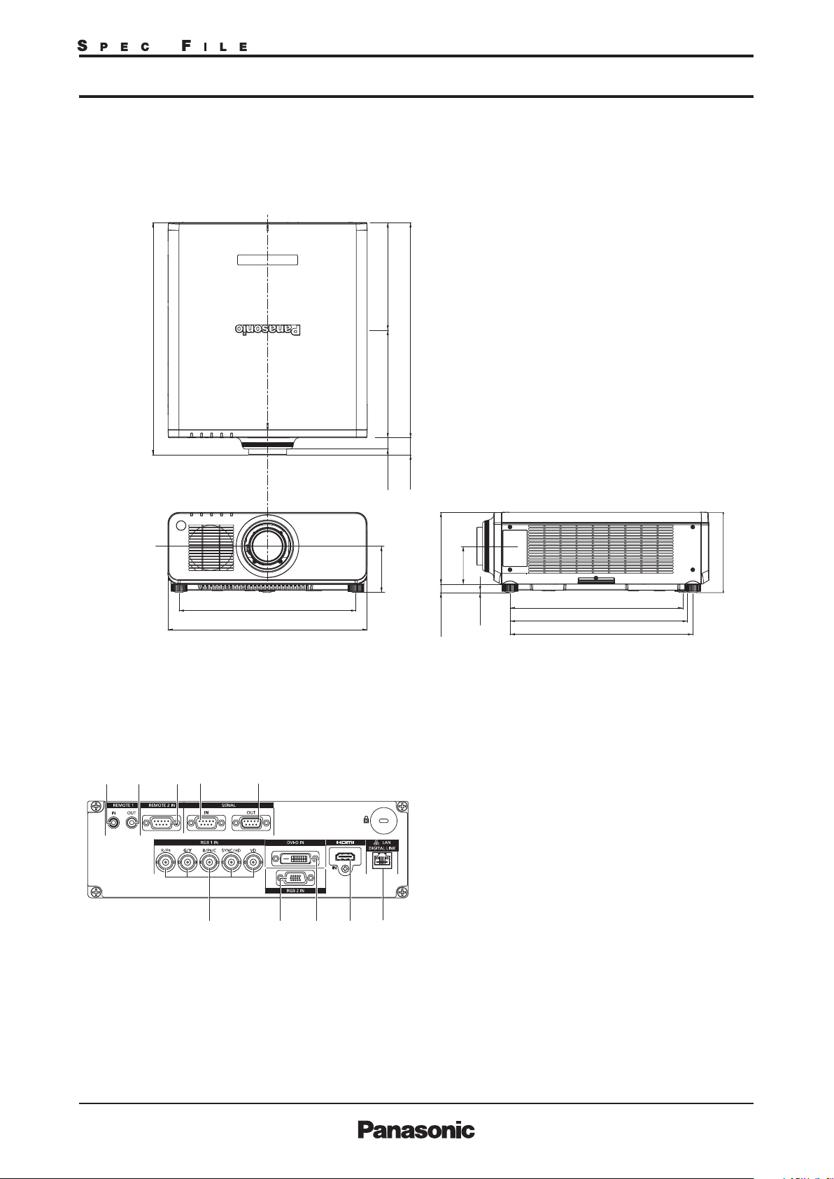
Dimensions
580.8
(22-7/8)
PT-RW630B/RW630W/RW630LB/RW630LW
(10-19/32)(10-19/32)
538
(21-3/16)
Terminals
1
442 (17-13/32)
498 (19-19/32)
2345
678910
269 269
28
115.5
(4-9/16)
42.8
(1-3/32)
(1-11/16)
181
19
(7-1/8)
96.5
(3/4)
unit : mm (inch)
NOTE: This illustration is not drawn to scale.
The illustration shows the PT-RW630B/RW630W.
(3-13/16)
4
(5/32)
432 (17)
444 (15/32)
457 (18)
1 Remote 1 input
2 Remote 1 output
3 Remote 2 input
4 Serial input
5 Serial output
6 RGB 1 input
7 RGB 2 Input
8 DVI-D input
9 HDMI input
10 LAN/DIGITAL LINK connector
200
(7-7/8)
As of September 2014 5/18
SFD14M022
Page 6
DLPTM Projector
PT-RW630B/RW630W/RW630LB/RW630LW
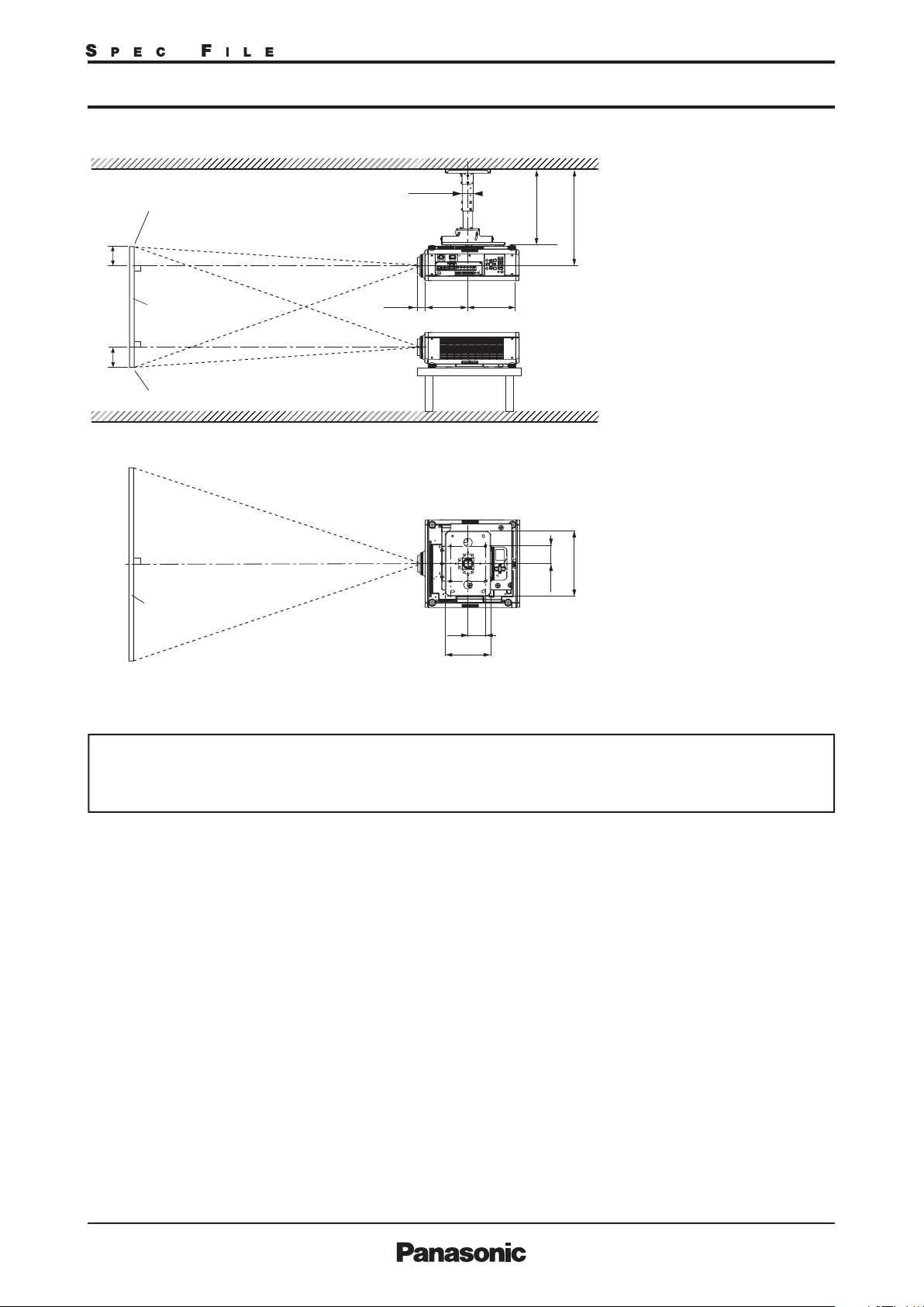
Standard setting-up position (If using other than the ET-DLE030)
2
*
352–432
(13-27/32–17)
294244
Upper edge of projected image
EE
ø60.5
L
1
*
(11-9/16)(9-19/32)
*1 When the lens protrudes to the maximum.
2
463.5–543.5*
84 mm (3-5/16 in) with the ET-DLE085
43 mm (1-11/16 in) with the supplied lens
44 mm (1-23/32 in) with the ET-DLE150
45 mm (1-25/32 in) with the ET-DLE250
51mm (2 in) with the ET-DLE350
95mm (3 -3/4 in) with the ET-DLE450
27 mm (1-1/16 in) with the ET-DLE055
*2 Adjustable in 40 mm (1-9/16 in) steps.
(18-1/4–21-13/32)
Lower edge of projected image
unit : mm (inch)
370
100
Projected image
100
(3-15/16)
259
(10-3/16)
(14-9/16)
(3-15/16)
NOTE:
Illustrations show the projector
installed using optional ceiling mount
bracket ET-PKD120H, optional bracket
assembly ET-PKD130B and an optional
lens.
This illustration is not drawn to scale.
Caution:
• All construction work should be done by a qualified technician.
• When mounting to the ceiling, use the special mounting bracket. Furthermore, in order to prevent it from falling
down from the ceiling, use the supplied wire on the mounting bracket.
As of September 2014 6/18
SFD14M022
Page 7

)H
)H
DLPTM Projector
PT-RW630B/RW630W/RW630LB/RW630LW
Projection distance for 16:10 aspect ratio screen (If using other than the ET-DLE030)
Screen size
(diagonal)
/
1.27
/
1.52
/
1.78
/
2.03
/
2.29
/
100
2.54
/
120
3.05
/
150
3.81
/
200
5.08
/
250
6.35
/
300
7.62
/
400
10.16
/
500
12.70
/
600
15.24
50
60
70
80
90
ET-DLE085
Zoom lens
min.[m][in] max.
0.83
1.00
1.17
1.35
1.52
1.70
2.05
2.57
3.44
4.31
5.18
6.93
8.67
10.75
10.42
12.91
ET-DLE150
Zoom lens
min. max. min. max.
1.38
1.04
1.25
1.47
1.68
1.90
2.11
2.55
3.19
4.27
5.35
6.43
8.59
1.66
1.95
2.23
2.52
2.81
3.38
4.24
5.67
7.10
8.53
11.39
14.25
17.11
2.01
2.43
2.84
3.25
3.66
4.08
4.90
6.14
8.20
10.26
12.33
16.45
20.58
24.70
Distance to screen (L
Zoom
Supplied lens ET-DLE250
1.82
2.57
2.20
3.10
2.58
3.63
2.95
4.16
3.33
4.69
3.71
5.21
4.47
6.27
5.61
7.86
7.50
10.50
9.39
13.15
11.28
15.79
15.07
21.08
18.86
26.36
22.64
31.65
Zoom lens
min. max. m in. max. min. max.
2.42
2.92
3.42
3.92
4.42
4.92
5.91
7.41
11.75
9.91
15.70
12.41
19.64
14.91
23.59
19.90
31.48
24.90
39.37
29.89
47.26
Fixed-focus
3.87
4.65
5.44
6.23
7.02
7.81
9.39
ET-DLE350
Zoom lens
3.80
4.59
5.38
6.16
6.95
7.74
9.31
11.68
15.61
19.55
23.49
31.36
39.24
47.11
5.82
7.00
8.19
9.38
10.57
11.76
14.14
17.71
23.66
29.61
35.56
47.46
59.36
71.26
ET-DLE450
Zoom lens
5.66
6.85
8.04
9.24
10.43
11.62
14.00
17.58
23.54
29.50
35.46
47.38
59.30
71.22
9.12
11.01
12.89
14.78
16.66
18.55
22.32
27.97
37.39
46.81
56.24
75.08
93.93
112.77
ET-DLE055
Fixed-focus
lens
0.83
1.00
1.18
1.35
1.53
1.70
2.05
2.58
3.45
–
–
–
–
–
Unit: meters
eight from the edge
of screen to
center of lens (H)
Fixed-
Zoom
–
–
–
–
–
–
–
–
–
–
–
–
–
–
0.34
0.40
0.47
0.54
0.61
0.67
0.81
1.01
1.35
1.68
2.02
2.69
3.37
4.04
focus
lens
0.34
0.40
0.47
0.54
0.61
0.67
0.81
1.01
1.35
lenses
0.00
0.00
0.00
0.00
0.00
0.00
0.00
0.00
0.00
0.00
0.00
0.00
0.00
0.00
–
–
–
–
–
Screen size
(diagonal)
ET-DLE085
Zoom lens
[m][in]
/
1.27
/
1.52
/
1.78
/
2.03
/
2.29
/
2.54
/
3.05
/
3.81
/
5.08
/
6.35
/
7.62
/
10.16
/
12.70
/
15.24
•The value for L (distance to screen) varies slightly within ±5% depending on the zoom lens characteristics.
•The zoom lens characteristics may cause slight image distortion.
•When vertical keystone correction is used, the image is corrected in the direction that reduces its projected size.
•The brightness varies depending on the zoom setting.
Note: When the ET-DLE055 is mounted, the optical lens shift function cannot be used.
60
90
100
120
150
200
250
300
400
500
600
50
70
80
min. max.
2.7
3.3
3.9
4.4
5.0
5.6
6.7
8.4
10.5
11.3
14.0
14.1
17.6
17.0
21.1
22.7
28.2
28.5
35.3
34.2
42.3
ET-DLE150
Zoom lens
min. max. min. max.
4.5
3.4
4.1
4.8
5.5
6.2
6.9
8.4
5.5
6.4
7.3
8.3
9.2
11.1
13.9
18.6
23.3
28.0
37.4
46.7
56.1
6.6
8.0
9.3
10.7
12.0
13.4
16.1
20.1
26.9
33.7
40.4
54.0
67.5
81.0
Distance to screen (L
Zoom
Supplied lens ET-DLE250
min. max. m in. max. min. max.
6.0
8.4
7.2
10.2
11.9
13.6
15.4
17.1
20.6
25.8
34.5
43.1
51.8
69.1
86.5
11.2
12.8
14.5
16.1
19.4
24.3
32.5
40.7
48.9
65.3
81.7
98.1
8.5
9.7
10.9
12.2
14.7
18.4
24.6
30.8
37.0
49.4
61.9
74.3
103.8
Zoom lens
7.9
12.7
9.6
15.3
17.9
20.4
23.0
25.6
30.8
38.6
51.5
64.4
77.4
103.3
129.2
155.0
ET-DLE350
Zoom lens
12.5
15.1
17.6
20.2
22.8
25.4
30.6
38.3
51.2
64.1
77.1
102.9
128.7
154.6
19.1
23.0
26.9
30.8
34.7
38.6
46.4
58.1
77.6
97.1
116.7
155.7
194.7
233.8
ET-DLE450
Zoom lens
18.6
22.5
26.4
30.3
34.
2
38.1
45.9
57.7
77.2
96.8
116.3
155.4
194.6
233.7
29.9
36.1
42.3
48.5
54.7
60.8
73.2
91.8
122.7
153.6
184.5
246.3
308.2
370.0
Fixed-focus
ET-DLE055
Fixed-focus
lens
2.7
3.3
3.9
4.4
5.0
5.6
6.7
8.5
11.3
–
–
–
–
–
Unit: feet
eight from the edge
of screen to
center of lens (H)
Zoom
Fixed-
–
–
–
–
–
–
–
–
–
–
–
–
–
–
1.1
1.3
1.6
1.8
2.0
2.2
2.7
3.3
4.4
5.5
6.6
8.8
11.0
13.3
focus
lens
1.1
1.3
1.6
1.8
2.0
2.2
2.7
3.3
4.4
lenses
0.0
0.0
0.0
0.0
0.0
0.0
0.0
0.0
0.0
0.0
0.0
0.0
0.0
0.0
–
–
–
–
–
As of September 2014 7/18
SFD14M022
Page 8

)H
)H
DLPTM Projector
PT-RW630B/RW630W/RW630LB/RW630LW
Projection distance for 16:9 aspect ratio screen (If using other than the ET-DLE030)
Screen size
(diagonal)
[m][in]
1.27
/
1.52
/
1.78
/
2.03
/
2.29
/
2.54
100
/
3.05
120
/
3.81
150
/
5.08
200
/
6.35
250
/
/
7.62
300
10.16
400
/
12.70
500
/
15.24
600
/
50
60
70
80
90
ET-DLE085
Zoom lens
min. max.
0.85
1.03
1.21
1.39
1.57
1.75
2.10
2.64
3.54
4.43
5.33
7.12
8.91
11.05
10.71
13.27
ET-DLE150
Zoom lens
min. max. min. max.
1.42
1.71
2.00
2.30
2.59
2.89
3.47
4.36
5.83
7.29
8.76
11.70
14.64
17.58
2.07
2.49
2.92
3.34
3.77
4.19
5.04
6.31
8.43
10.55
12.67
16.91
21.15
25.39
1.07
1.29
1.51
1.73
1.95
2.17
2.62
3.28
4.39
5.50
6.61
8.83
Distance to screen (L
Zoom
Supplied lens ET-DLE250
min. max. min. max. min. max.
1.87
2.26
2.65
3.04
3.43
3.82
4.60
5.76
7.71
9.65
11.60
15.49
19.38
23.27
2.64
3.19
3.73
4.28
4.82
5.36
6.45
8.08
10.80
13.51
16.23
21.66
27.10
32.53
2.49
3.00
3.51
4.03
4.54
5.05
6.08
7.62
10.19
12.76
15.32
20.46
25.59
30.72
Zoom lens
3.98
4.79
5.60
6.41
7.22
8.03
9.65
12.08
16.14
20.19
24.25
32.35
40.46
48.57
ET-DLE350
Zoom lens
3.91
4.72
5.53
6.34
7.15
7.96
9.58
12.00
16.05
20.10
24.14
32.24
40.33
48.42
5.98
7.20
8.43
9.65
10.87
12.09
14.54
18.21
24.32
30.44
36.55
48.78
61.01
73.24
ET-DLE450
Zoom lens
5.82
7.05
8.28
9.50
10.73
11.95
14.40
18.08
24.20
30.33
36.45
48.71
60.96
73.21
9.39
11.32
13.26
15.20
17.13
19.07
22.94
28.75
38.44
48.12
57.81
77.18
96.55
115.92
Fixed-focus
ET-DLE055
Fixed-focus
lens
0.85
1.03
1.21
1.39
1.57
1.75
2.11
2.65
3.55
–
–
–
–
–
Unit: meters
eight from the edge
of screen to
center of lens (H)
Fixed-
Zoom
–
–
–
–
–
–
–
–
–
–
–
–
–
–
0.31
0.37
0.44
0.50
0.56
0.62
0.75
0.93
1.25
1.56
1.87
2.49
3.11
3.74
focus
lens
0.31
0.37
0.44
0.50
0.56
0.62
0.75
0.93
1.25
lenses
-0.06
-0.08
-0.09
-0.10
-0.11
-0.13
-0.15
-0.19
-0.25
-0.31
-0.37
-0.50
-0.62
-0.75
–
–
–
–
–
Screen size
(diagonal)
ET-DLE085
Zoom lens
[m][in]
/
1.27
/
1.52
/
1.78
/
2.03
/
2.29
/
2.54
/
3.05
/
3.81
/
5.08
/
6.35
/
7.62
/
10.16
/
12.70
/
15.24
• The value for L (distance to screen) varies slightly within ±5% depending on the zoom lens characteristics.
• The zoom lens characteristics may cause slight image distortion.
• When vertical keystone correction is used, the image is c orrected in the direction that reduces its projected size.
• The brightness varies depending on the zoom setting.
Note: When the ET-DLE055 is mounted, the optical lens shift function cannot be used.
60
90
100
120
150
200
250
300
400
500
600
50
70
80
min. max.
2.8
3.4
4.0
4.6
5.1
5.7
6.9
8.7
10.8
11.6
14.4
14.5
18.1
17.5
21.7
23.4
29.0
29.2
36.3
35.1
43.5
ET-DLE150
Zoom lens
min. max. min. max.
4.6
3.5
4.2
5.0
5.7
6.4
7.1
8.6
5.6
6.6
7.5
8.5
9.5
11.4
14.3
19.1
23.9
28.8
38.4
48.0
57.7
6.8
8.2
9.6
11.0
12.4
13.8
16.5
20.7
27.7
34.6
41.6
55.5
69.4
83.3
Distance to screen (L
Zoom
Supplied lens ET-DLE250
min. max. min. max. min. max.
6.1
8.7
7.4
10.5
12.2
14.0
15.8
17.6
21.2
26.5
35.4
44.3
53.2
71.1
88.9
11.5
13.2
14.9
16.6
20.0
25.0
33.4
41.8
50.3
67.1
84.0
100.8
8.7
10.0
11.2
12.5
15.1
18.9
25.3
31.7
38.1
50.8
63.6
106.776.4
Zoom lens
8.2
13.0
9.8
15.7
18.4
21.0
23.7
26.3
31.7
39.6
52.9
66.2
79.5
106.1
132.7
159.4
ET-DLE350
Zoom lens
12.8
15.5
18.1
20.8
23.5
26.1
31.4
39.4
52.7
65.9
79.2
105.8
132.3
158.9
19.6
23.6
27.6
31.7
35.7
39.7
47.7
59.7
79.8
99.9
119.9
160.0
200.2
240.3
ET-DLE450
Zoom lens
19.1
23.1
27.1
31.2
35.2
39.2
47.2
59.3
79.4
99.5
119.6
159.8
200.0
240.2
30.8
37.1
43.5
49.9
56.2
62.6
75.3
94.3
126.1
157.9
189.7
253.2
316.8
380.3
Fixed-focus
ET-DLE055
Fixed-focus
lens
2.8
3.4
4.0
4.6
5.2
5.7
6.9
8.7
11.7
–
–
–
–
–
Unit: feet
eight from the edge
of screen to
center of lens (H)
Zoom
Fixed-
–
–
–
–
–
–
–
–
–
–
–
–
–
–
1.0
1.2
1.4
1.6
1.8
2.0
2.5
3.1
4.1
5.1
6.1
8.2
10.2
12.3
focus
lens
1.0
1.2
1.4
1.6
1.8
2.0
2.5
3.1
4.1
lenses
-0.2
-0.3
-0.3
-0.3
-0.4
-0.4
-0.5
-0.6
-0.8
-1.0
-1.2
-1.6
-2.0
-2.5
–
–
–
–
–
As of September 2014 8/18
SFD14M022
Page 9

)H
)H
DLPTM Projector
PT-RW630B/RW630W/RW630LB/RW630LW
Projection distance for 4:3 aspect ratio screen (If using other than the ET-DLE030)
Screen size
(diagonal)
[m][in]
1.27
/
1.52
/
1.78
/
2.03
/
2.29
/
2.54
100
/
3.05
120
/
3.81
150
/
5.08
200
/
6.35
250
/
/
7.62
300
10.16
400
/
12.70
500
/
15.24
600
/
50
60
70
80
90
ET-DLE085
Zoom lens
min. max.
0.94
1.14
1.34
1.53
1.73
1.93
2.32
2.91
3.90
4.89
5.88
7.85
9.82
12.17
11.80
14.62
ET-DLE150
Zoom lens
min. max. min. max.
1.57
1.89
2.21
2.54
2.86
3.18
3.83
4.80
6.42
8.04
9.66
12.90
16.13
19.37
2.29
2.75
3.22
3.69
4.15
4.62
5.56
6.96
9.29
11.63
13.96
18.63
23.30
27.97
1.18
1.42
1.67
1.91
2.16
2.40
2.89
3.62
4.84
6.07
7.29
9.73
Distance to screen (L
Zoom
Supplied lens ET-DLE250
min. max. min. max. min. max.
2.07
2.50
2.93
3.35
3.78
4.21
5.07
6.36
8.50
10.64
12.78
17.07
21.36
2.92
3.52
4.12
4.72
5.31
5.91
7.11
8.91
11.90
14.89
17.88
23.87
29.85
35.8425.64
2.75
3.31
3.88
4.44
5.01
5.58
6.71
8.40
11.23
14.06
16.88
22.54
28.19
33.85
Zoom lens
4.39
5.28
6.17
7.07
7.96
8.85
10.64
13.32
17.78
22.25
26.71
35.65
44.58
53.51
ET-DLE350
Zoom lens
4.32
5.21
6.11
7.00
7.89
8.78
10.56
13.24
17.69
22.15
26.61
35.52
44.44
53.35
6.60
7.95
9.29
10.64
11.99
13.34
16.03
20.07
26.81
33.54
40.28
53.74
67.21
80.68
ET-DLE450
Zoom lens
6.45
7.80
9.15
10.49
11.84
13.19
15.89
19.94
26.69
33.44
40.18
53.68
67.17
80.67
10.37
12.50
14.64
16.77
18.90
21.04
25.30
31.70
42.37
53.04
63.70
85.04
106.37
127.71
Fixed-focus
ET-DLE055
Fixed-focus
lens
0.94
1.14
1.34
1.54
1.74
1.93
2.33
2.93
3.92
–
–
–
–
–
Unit: meters
eight from the edge
of screen to
center of lens (H)
Fixed-
Zoom
–
–
–
–
–
–
–
–
–
–
–
–
–
–
0.38
0.46
0.53
0.61
0.69
0.76
0.91
1.14
1.52
1.91
2.29
3.05
3.81
4.57
focus
lens
0.38
0.46
0.53
0.61
0.69
0.76
0.91
1.14
1.52
lenses
0.00
0.00
0.00
0.00
0.00
0.00
0.00
0.00
0.00
0.00
0.00
0.00
0.00
0.00
–
–
–
–
–
Screen size
(diagonal)
ET-DLE085
Zoom lens
[m][in]
/
1.27
/
1.52
/
1.78
/
2.03
/
2.29
/
2.54
/
3.05
/
3.81
/
5.08
/
6.35
/
7.62
/
10.16
/
12.70
/
15.24
• The value for L (distance to screen) varies slightly within ±5% depending on the zoom lens characteristics.
• The zoom lens characteristics may cause slight image distortion.
• When vertical keystone correction is used, the image is c orrected in the direction that reduces its projected size.
• The brightness varies depending on the zoom setting.
Note: When the ET-DLE055 is mounted, the optical lens shift function cannot be used.
60
90
100
120
150
200
250
300
400
500
600
50
70
80
min. max.
3.1
3.7
4.4
5.0
5.7
6.3
7.6
9.6
11.9
12.8
15.9
16.0
19.9
19.3
23.9
25.8
31.9
32.2
39.9
38.7
48.0
ET-DLE150
Zoom lens
min. max. min. max.
5.1
3.9
4.7
5.5
6.3
7.1
7.9
9.5
6.2
7.3
8.3
9.4
10.4
12.6
15.8
21.1
26.4
31.7
42.3
52.9
63.6
7.5
9.0
10.6
12.1
13.6
15.2
18.2
22.8
30.5
38.1
45.8
61.1
76.5
91.8
Distance to screen (L
Zoom
Supplied lens ET-DLE250
min. max. min. max. min. max.
6.8
9.6
11.5
13.5
15.5
17.4
19.4
23.3
29.2
39.0
48.9
58.7
78.3
97.9
10.9
12.7
14.6
16.4
18.3
22.0
27.6
36.8
46.1
55.4
73.
92.5
111.0
8.2
9.6
11.0
12.4
13.8
16.6
20.8
27.9
34.9
41.9
56.0
70.1
117.684.1
Zoom lens
9.0
14.4
17.3
20.3
23.2
26.1
29.0
34.9
43.7
58.3
73.0
87.6
116.9
9
146.2
175.5
ET-DLE350
Zoom lens
14.2
17.1
20.0
23.0
25.9
28.8
34.7
43.4
58.0
72.7
87.3
116.5
145.8
175.0
21.7
26.1
30.5
34.9
39.3
43.8
52.6
65.8
87.9
110.0
132.1
176.3
220.5
264.7
ET-DLE450
Zoom lens
21.1
25.6
30.0
34.4
38.9
43.3
52.1
65.4
87.6
109.7
131.8
176.1
220.4
264.7
34.0
41.0
48.0
55.0
62.0
69.0
83.0
104.0
139.0
174.0
209.0
279.0
349.0
419.0
Fixed-focus
ET-DLE055
Fixed-focus
lens
3.1
3.7
4.4
5.0
5.7
6.3
7.6
9.6
12.8
–
–
–
–
–
Unit: feet
eight from the edge
of screen to
center of lens (H)
Zoom
Fixed-
–
–
–
–
–
–
–
–
–
–
–
–
–
–
1.3
1.5
1.8
2.0
2.3
2.5
3.0
3.8
5.0
6.3
7.5
10.0
12.5
15.0
focus
lens
1.3
1.5
1.8
2.0
2.3
2.5
3.0
3.8
5.0
lenses
0.0
0.0
0.0
0.0
0.0
0.0
0.0
0.0
0.0
0.0
0.0
0.0
0.0
0.0
–
–
–
–
–
As of September 2014 9/18
SFD14M022
Page 10

DLPTM Projector
PT-RW630B/RW630W/RW630LB/RW630LW
Standard setting-up position (If using the ET-DLE030)
2
ø60.5
(21-1/2–
27-25/32)
546〜706*
*1 When the lens protrudes to the maximum.
84 mm (3-5/16 in) with the ET-DLE085
43 mm (1-11/16 in) wi th the supplied lens
44 mm (1-23/32 in) wi th the ET-DLE150
45 mm (1-25/32 in) wi th the ET-DLE250
51mm (2 in) with the ET-DLE350
95mm (3 -3/4 in) with the ET-DLE450
27 mm (1-1/16 in) with the ET-DLE055
*2 Adjustable in 40 mm (1-9/16 in) steps.
A2
A1
Upper edge of
projected image
Projected image
Lower edge of
projected image
A1
A2
L4
L4
299.5
(11-25/32)
L3
L1
L1
L3
238.5
(9-3/8)
unit : mm (inch)
NOTE:
Illustrations show the projector
installed using optional ceiling mount
bracket ET-PKD130H, optional bracket
assembly ET-PKD130B and an optional lens.
This illustration is not drawn to scale.
100
(3-15/16)
380
Projected image
100
(3-15/16)
308
(12-1/8)
(14-31/32)
Caution:
• All construction work should be done by a qualified technician.
• When mounting to the ceiling, use the special mounting bracket. Furthermore, in order to prevent it from falling
down from the ceiling, use the supplied wire on the mounting bracket.
As of September 2014 10/18
SFD14M022
Page 11

DLPTM Projector
PT-RW630B/RW630W/RW630LB/RW630LW
Projection distance for 16:10 aspect ratio screen (If using the ET-DLE030)
Unit : meters
Ultra-short focal length lens ET-DLE030
Close-up system dimensions
Throw ratio
Diagonal
(Inches)
Diagonal
(Inches)
* The value for L1 may contain an error of within ±5%.
* When using vertical keystone correction, the images will be corrected so that they will tend to be smaller than the specified screen size.
* This measurement is not the distance between the rear of the projector and the wall, but is instead the distance between the rear of the projector and the screen surface.
Leave at least 500 mm of space between the rear of the projector and the wall and any other objects in order to provide adequate ventilation space. If setting up the
Diagonal
image
size
100
120
150
200
250
300
350
Diagonal
image
size
100
120
150
200
250
300
350
projector in a closed room, be sure to provide separate air conditioning and ventilation equipment. If there is insufficient ventilation in the room, radiated heat may build up
and cause the protection circuit of the projector to operate.
image
size
(m)
2.54
3.05
3.81
5.08
6.35
7.62
8.89
Throw ratio
image
size
(m)
2.54
3.05
3.81
5.08
6.35
7.62
8.89
Height
(SH)
1.35
1.62
2.02
2.69
3.37
4.04
4.71
Height
(SH)
4.4
5.3
6.6
8.8
11.0
13.3
15.5
Width
(SW)
2.15
2.59
3.23
4.31
5.39
6.46
7.54
Width
(SW)
7.1
8.5
10.6
14.1
17.7
21.2
24.7
0.40:1
Projection distance
(From mirror reflective
surface to screen)
(L1)
0.86 0.69 0.16 0.59 0.79
1.03 0.86 0.33 0.72 0.92
1.29 1.12 0.58 0.92 1.12
1.71 1.55 1.01 1.25 1.45
2.14 1.98 1.44 1.58 1.78
2.57 2.40 1.86 1.91 2.11
3.00 2.83 2.29 2.24 2.44
0.40:1
Projection distance
(From mirror reflective
surface to screen)
(L1)
2.8 2.3 0.5 1.9 2.6
3.4 2.8 1.1 2.4 3.0
4.2 3.7 1.9 3.0 3.7
5.6 5.1 3.3 4.1 4.8
7.0 6.5 4.7 5.2 5.8
8.4 7.9 6.1 6.3 6.9
9.8 9.3 7.5 7.3 8.0
From front of
set to screen
(L3)
Ultra-short focal length lens ET-DLE030
From front of
set to screen
(L3)
From rear of
set to screen
(L4)
Close-up system dimensions
From rear of
set to screen
(L4)
From top of set to
bottom edge of
screen (A1)
From top of set to
bottom edge of
screen (A1)
From bottom of set
to bottom edge of
screen (A2)
From bottom of set
to bottom edge of
screen (A2)
Unit : feet
Screen
A1
A2
L1
L3
L1: Projection distance
(from screen to mirror reflective surface)
L3: From screen to front of set
L4
L4: From screen to rear of set
A1: From bottom edge of screen to top of set
A2: From bottom edge of screen to bottom of set
Projection Distance Calculation Table
Screen aspect ratio 16:10
Projection distance calculation formula
L1 (m) = 0.3205 x Diagonal image size + 0.0047
Calculation formula for distance from top of set to bottom edge of screen
A1 (m) = 0.1977 x Diagonal image size - 0.07210
As of September 2014 11/18
SFD14M022
Page 12

DLPTM Projector
PT-RW630B/RW630W/RW630LB/RW630LW
Projection distance for 16:9 aspect ratio screen (If using the ET-DLE030)
Unit : meters
Ultra-short focal length lens ET-DLE030
Close-up system dimensions
Throw ratio
Diagonal
(Inches)
Diagonal
(Inches)
* The value for L1 may contain an error of within ±5%.
* When using vertical keystone correction, the images will be corrected so that they will tend to be smaller than the specified screen size.
* This measurement is not the distance between the rear of the projector and the wall, but is instead the distance between the rear of the projector and the screen surface.
Leave at least 500 mm of space between the rear of the projector and the wall and any other objects in order to provide adequate ventilation space. If setting up the
Diagonal
image
size
100
120
150
200
250
300
350
Diagonal
image
size
100
120
150
200
250
300
350
projector in a closed room, be sure to provide separate air conditioning and ventilation equipment. If there is insufficient ventilation in the room, radiated heat may build up
and cause the protection circuit of the projector to operate.
image
size
(m)
2.54
3.05
3.81
5.08
6.35
7.62
8.89
Throw ratio
image
size
(m)
2.54
3.05
3.81
5.08
6.35
7.62
8.89
Height
(SH)
1.25
1.49
1.87
2.49
3.11
3.74
4.36
Height
(SH)
4.1
4.9
6.1
8.2
10.2
12.3
14.3
Width
(SW)
2.21
2.66
3.32
4.43
5.54
6.64
7.75
Width
(SW)
7.3
8.7
10.9
14.5
18.2
21.8
25.4
0.40:1
Projection distance
(From mirror reflective
surface to screen)
(L1)
0.88 0.72 0.18 0.67 0.87
1.06 0.89 0.35 0.82 1.02
1.32 1.16 0.62 1.05 1.25
1.76 1.60 1.06 1.42 1.62
2.20 2.03 1.50 1.79 1.99
2.64 2.47 1.94 2.17 2.37
3.08 2.91 2.38 2.54 2.74
0.40:1
Projection distance
(From mirror reflective
surface to screen)
(L1)
2.9 2.4 0.6 2.2 2.9
3.5 2.9 1.1 2.7 3.3
4.3 3.8 2.0 3.4 4.1
5.8 5.2 3.5 4.7 5.3
7.2 6.7 4.9 5.9 6.5
8.7 8.1 6.4 7.1 7.8
10.1 9.5 7.8 8.3 9.0
From front of
set to screen
(L3)
Ultra-short focal length lens ET-DLE030
From front of
set to screen
(L3)
From rear of
set to screen
(L4)
Close-up system dimensions
From rear of
set to screen
(L4)
From top of set to
bottom edge of
screen (A1)
From top of set to
bottom edge of
screen (A1)
From bottom of set
to bottom edge of
screen (A2)
From bottom of set
to bottom edge of
screen (A2)
Unit : feet
Screen
A1
A2
L1
L3
L1: Projection distance
(from screen to mirror reflective surface)
L3: From screen to front of set
L4
L4: From screen to rear of set
A1: From bottom edge of screen to top of set
A2: From bottom edge of screen to bottom of set
Projection Distance Calculation Table
Screen aspect ratio 16:9
Projection distance calculation formula
L1 (m) = 0.3294 x Diagonal image size + 0.0047
Calculation formula for distance from top of set to bottom edge of screen
A1 (m) = 0.2304 x Diagonal image size - 0.07210
As of September 2014 12/18
SFD14M022
Page 13

DLPTM Projector
PT-RW630B/RW630W/RW630LB/RW630LW
Projection distance for 4:3 aspect ratio screen (If using the ET-DLE030)
Unit : meters
Ultra-short focal length lens ET-DLE030
Close-up system dimensions
Throw ratio
Diagonal
(Inches)
Diagonal
(Inches)
* The value for L1 may contain an error of within ±5%.
* When using vertical keystone correction, the images will be corrected so that they will tend to be smaller than the specified screen size.
* This measurement is not the distance between the rear of the projector and the wall, but is instead the distance between the rear of the projector and the screen surface.
Leave at least 500 mm of space between the rear of the projector and the wall and any other objects in order to provide adequate ventilation space. If setting up the
Diagonal
image
size
100
120
150
200
250
300
350
Diagonal
image
size
100
120
150
200
250
300
350
projector in a closed room, be sure to provide separate air conditioning and ventilation equipment. If there is insufficient ventilation in the room, radiated heat may build up
and cause the protection circuit of the projector to operate.
image
size
(m)
2.54
3.05
3.81
5.08
6.35
7.62
8.89
Throw ratio
image
size
(m)
2.54
3.05
3.81
5.08
6.35
7.62
8.89
Height
(SH)
1.52
1.83
2.29
3.05
3.81
4.57
5.33
Height
(SH)
5.0
6.0
7.5
10.0
12.5
15.0
17.5
Width
(SW)
2.03
2.44
3.05
4.06
5.08
6.10
7.11
Width
(SW)
6.7
8.0
10.0
13.3
16.7
20.0
23.3
0.48:1
Projection distance
(From mirror reflective
surface to screen)
(L1)
0.97 0.81 0.27 0.67 0.87
1.17 1.00 0.46 0.82 1.02
1.46 1.29 0.75 1.05 1.25
1.94 1.77 1.24 1.42 1.62
2.42 2.26 1.72 1.79 1.99
2.91 2.74 2.20 2.17 2.37
3.39 3.22 2.69 2.54 2.74
0.48:1
Projection distance
(From mirror reflective
surface to screen)
(L1)
3.2 2.7 0.9 2.2 2.9
3.8 3.3 1.5 2.7 3.3
4.8 4.2 2.5 3.4 4.1
6.4 5.8 4.1 4.7 5.3
7.9 7.4 5.6 5.9 6.5
9.5 9.0 7.2 7.1 7.8
11.1 10.6 8.8 8.3 9.0
From front of
set to screen
(L3)
Ultra-short focal length lens ET-DLE030
From front of
set to screen
(L3)
From rear of
set to screen
(L4)
Close-up system dimensions
From rear of
set to screen
(L4)
From top of set to
bottom edge of
screen (A1)
From top of set to
bottom edge of
screen (A1)
From bottom of set
to bottom edge of
screen (A2)
From bottom of set
to bottom edge of
screen (A2)
Unit : feet
Screen
A1
A2
L1
L3
L1: Projection distance
(from screen to mirror reflective surface)
L3: From screen to front of set
L4
L4: From screen to rear of set
A1: From bottom edge of screen to top of set
A2: From bottom edge of screen to bottom of set
Projection Distance Calculation Table
Screen aspect ratio 4:3
Projection distance calculation formula
L1 (m) = 0.3628 x Diagonal image size + 0.0047
Calculation formula for distance from top of set to bottom edge of screen
A1 (m) = 0.2238 x Diagonal image size - 0.07210
As of September 2014 13/18
SFD14M022
Page 14

DLPTM Projector
PT-RW630B/RW630W/RW630LB/RW630LW
Calculation of the projection distance
For a screen size different from the above, use the equation below to calculate the projection distance.
Aspect ratio 16:10
ET-DLE085
ET-DLE150
Supplied lens
ET-DLE250
ET-DLE350
ET-DLE450
ET-DLE030 (fixed focus)
minimum L (m) = (diagonal screen size in inches) × 0.0183 - 0.0471
maximum L (m) = (diagonal screen size in inches) × 0.0227 - 0.0442
minimum L (m) = (diagonal screen size in inches) × 0.0300 - 0.0540
maximum L (m) = (diagonal screen size in inches) × 0.0433 - 0.0498
minimum L (m) = (diagonal screen size in inches) × 0.0398 - 0.0746
maximum L (m) = (diagonal screen size in inches) × 0.0555 - 0.0725
minimum L (m) = (diagonal screen size in inches) × 0.0524 - 0.0800
maximum L (m) = (diagonal screen size in inches) × 0.0828 - 0.0792
minimum L (m) = (diagonal screen size in inches) × 0.0827 - 0.1351
maximum L (m) = (diagonal screen size in inches) × 0.1249 - 0.1346
minimum L (m) = (diagonal screen size in inches) × 0.1252 - 0.3017
maximum L (m) = (diagonal screen size in inches) × 0.1979 - 0.2991
(fixed focus) L (m) = (diagonal screen size in inches) × 0.0184 - 0.0476ET-DLE055
Aspect ratio 16:9
ET-DLE085
ET-DLE150
Supplied lens
ET-DLE250
ET-DLE350
ET-DLE450
ET-DLE030 (fixed focus)
minimum L (m) = (diagonal screen size in inches) × 0.0188 - 0.0471
maximum L (m) = (diagonal screen size in inches) × 0.0233 - 0.0442
minimum L (m) = (diagonal screen size in inches) × 0.0309 - 0.0540
maximum L (m) = (diagonal screen size in inches) × 0.0445 - 0.0498
minimum L (m) = (diagonal screen size in inches) × 0.0409 - 0.0746
maximum L (m) = (diagonal screen size in inches) × 0.0571 - 0.0725
minimum L (m) = (diagonal screen size in inches) × 0.0539 - 0.0800
maximum L (m) = (diagonal screen size in inches) × 0.0851 - 0.0792
minimum L (m) = (diagonal screen size in inches) × 0.0850 - 0.1351
maximum L (m) = (diagonal
minimum L (m) = (diagonal screen size in inches) × 0.1286 - 0.3017
maximum L (m) = (diagonal screen size in inches) × 0.2034 - 0.2991
(fixed focus) L (m) = (diagonal screen size in inches) × 0.0189 - 0.0476ET-DLE055
L1 (m) = (diagonal screen size in inches) × 0.0085 - 0.0047
L3 (m) = L1-0.166
L4 (m) = L1-0.704
screen size in inches) × 0.1284 - 0.1346
L1 (m) = (diagonal screen size in inches) × 0.0088 - 0.0047
L3 (m) = L1-0.166
L4 (m) = L1-0.704
Aspect ratio 4:3
ET-DLE085
ET-DLE150
Supplied lens
ET-DLE250
ET-DLE350
ET-DLE450
ET-DLE030 (fixed focus)
• Distances calculated with the a bove equations will include a slight erro r.
As of September 2014 14/18
SFD14M022
minimum L (m) = (diagonal screen size in inches) × 0.0207 - 0.0471
maximum L (m) = (diagonal screen size in inches) × 0.0257 - 0.0442
minimum L (m) = (diagonal screen size in inches) × 0.0340 - 0.0540
maximum L (m) = (diagonal screen size in inches) × 0.0490 - 0.0498
minimumL (m) = (diagonal screen size in inches) × 0.0450 - 0.0746
maximum L (m) = (diagonal screen size in inches) × 0.0628 - 0.0725
minimum L (m) = (diagonal screen size in inches) × 0.0594 - 0.0800
maximum L (m) = (diagonal screen size in inches) × 0.0938 - 0.0792
minimum L (m) = (diagonal screen size in inches) × 0.0936 - 0.1351
maximum L (m) = (diagonal screen size in inches) × 0.1414 - 0.1346
minimum L (m) = (diagonal screen size in inches) × 0.1417 - 0.3017
maximum L (m) = (diagonal screen size in inches) × 0.2240 - 0.2991
L1 (m) = (diagonal screen size in inches) × 0.0097 - 0.0047
L3 (m) = L1-0.166
L4 (m) = L1-0.704
(fixed focus) L (m) = (diagonal screen size in inches) × 0.0208 - 0.0476ET-DLE055
Page 15

DLPTM Projector
PT-RW630B/RW630W/RW630LB/RW630LW
Formula for calculating possible heights when using the ET-DLE030
If using a screen size which has not been previously mentioned, use the following calculation formulas to
obtain the possible setting-up height.
For screen aspect ratio of 16:10 Possible setting-up height A1 (mm) = Projection screen size (inches) x 6.6-74.0
Possible setting-up height A2 (mm) = A1 + 200
For screen aspect ratio of 16:9 Possible setting-up height A1 (mm) = Projection screen size (inches) x 7.5-74.0
Possible setting-up height A2 (mm) = A1 + 200
For screen aspect ratio of 4:3 Possible setting-up height A1 (mm) = Projection screen size (inches) x 7.5-74.0
Possible setting-up height A2 (mm) = A1 + 200
* There may be a small margin of error in the values obtained from the above formulas.
Shift range
Optical
axis shift function allows to shift the position of a projected image as shown below.
• Floor mount
(When the lens except the ET-DLE085 is mounted.)
Standard projection postition
Projected image height V
0.1H
Projected image width H
0.3H
0.1H
• Floor mount
(When the ET-DLE085 is mounted.)
Standard projection postition
0.28H
0.6V0.16V
0.6V0.16V
• Ceiling mount
(When the lens except the ET-DLE085 is mounted.)
0.6V 0.16V
Projected image width H
0.1H
0.3H
Standard projection postition
0.1H
V
Projected image height
• Ceiling mount
(When the ET-DLE085 is mounted.)
Projected image width H
0.1H
V
Projected image height
Projected image height V
0.1H
•The ET-DLE055 has a fixed short-focus lens. Therefore, the lens shift function provided in the main unit cannot be used.
Projected image width H
0.6V 0.16V
0.28H
Standard projection postition
As of September 2014 15/18
SFD14M022
Page 16

DLPTM Projector
Installable angle
Install the projector at an angle within the range shown below.
FULL 360-degree projection
PT-RW630B/RW630W/RW630LB/RW630LW
360°
Vertical 360-deg.
360°
Horizontal 360-deg. Tilting 360-deg.
(V&H combination)
360°
As of September 2014 16/18
SFD14M022
Page 17

DLPTM Projector
PT-RW630B/RW630W/RW630LB/RW630LW
List of compatible signals
The signals that can be input to this projector are shown in the table below. Horizontal scanning frequencies of 15 kHz to 100 kHz, vertical scanning frequencies of 24 Hz to 120 Hz, and a dot clock of
162 MHz maximum can be input.
NOTE: The native resolution of this projector is 1,280× 800 pixels. If the display resolution of the input signal is different from the
native resolution, image compression or expansion will be used to c onvert the input signal to a level within the native resolution.
Display mode
NTSC/NTSC4.43/PAL-M/PAL60
PAL/PAL-N/SECAM
525i (480i)
625i (576i)
525i (480i)
625i (576i)
525p (480p)
625p (576p)
750 (720)/60p
750 (720)/50p
1125 (1080)/60i*
1125 (1080)/50i
1125 (1080)/24p
1125 (1080)/24sF
1125 (1080)/25p
1125 (1080)/30p
1125 (1080)/60p
1125 (1080)/50p
VESA400
VGA480
SVGA
MAC16
XGA
MXGA
MAC21
1280 × 720
1280 × 768
3
Display
resolution
1
(dots)*
720 × 480i
720 × 576i
720 × 480i
720 × 576i
720(1440) × 480i*
720(1440) × 576i
720 × 483
720 × 576
1280 × 720
1920 × 1080i
1920 × 1080
1920 × 1080i
1920 × 1080
640 × 400
640 × 480
800 × 600
832 × 624
1024 × 768
1152 × 864
1152 × 870
1280 × 720
1280 × 768
1280 × 768
1280 × 768
*
Scanning frequency
(kHz)
15.7
15.6
15.7
15.6
2
15.7
15.6
31.5
31.3
45.0
37.5
33.8
28.1
27.0
27.0
28.1
33.8
67.5
56.3
31.5
37.9
31.5
35.0
37.9
37.5
43.3
35.2
37.9
48.1
46.9
53.7
49.7
39.6
48.4
56.5
60.0
65.5
68.7
81.4
98.8
53.7
64.0
67.5
77.1
68.7
37.1
44.8
76.3
92.6
39.6
47.8
4
47.4
60.3
68.6
H
V
(kHz)
59.9
50.0
59.9
50.0
59.9
50.0
59.9
50.0
60.0
50.0
60.0
50.0
24.0
48.0
25.0
30.0
60.0
50.0
70.1
85.1
59.9
66.7
72.8
75.0
85.0
56.3
60.3
72.2
75.0
85.1
74.6
50.0
60.0
70.1
75.0
81.6
85.0
100.0
120.0
60.0
70.0
74.9
85.0
75.1
49.8
59.9
100.0
120.0
49.9
59.9
60.0
74.9
84.8
Dot clock
frequency
(MHz)
−
13.5
27.0
74.3
148.5
25.2
31.5
25.2
30.2
31.5
31.5
36.0
36.0
40.0
50.0
49.5
56.3
57.3
51.9
65.0
75.0
78.8
86.0
94.5
113.3
139.1
81.6
94.2
108.0
119.7
100.0
60.5
74.5
131.8
161.6
65.3
79.5
68.3
102.3
117.5
Format
VIDEO/YC
RGB
HDMI/DVI-D
RGB/HDMI/DVI-D
RGB/HDMI/DVI-D
RGB/HDMI/DVI-D
As of September 2014 17/18
SFD14M022
Page 18

DLPTM Projector
PT-RW630B/RW630W/RW630LB/RW630LW
Display mode
1280 × 800
MSXGA
Display
resolution
1
(dots)*
1280 × 800
1280 × 800*
1280 × 800
1280 × 960
Scanning frequency
(kHz)
41.3
49.7
4
49.3
62.8
71.6
60.0
H
52.4
64.0
SXGA
1280 × 1024
72.3
78.2
80.0
91.1
1366×768
1366 × 768
47.7
39.6
54.1
64.0
SXGA+
1400 × 1050
65.2
65.3
78.8
82.2
WXGA+
1600×900
UXGA
WSXGA+
1440 × 900
1600 × 900
1600 × 1200
1680 × 1050
1920 × 1080
1920×1080
1920 × 1080*
1920 × 1080*
1920 × 1200
WUXGA
1920 × 1200*
1920 × 1200*
*1 The “i” appearing after the reso lution indicates an interlaced signal.
*2 Only compatible with dot clock frequency of 27 MHz (pixel repetition signal)
*3 When 1125(1035)/60i signal input, it displays as 1125(1080)/60i signals.
*4 Compliant with VESA CVT-RB (Coordinated Video Timing-Reduced Blanking).
*5 Image resolution is reduced by the image processing circuit before projection.
55.9
46.3
46.4
55.9 60.0
61.8
75.0
65.3
54.1
55.6
4
66.6
5
67.2
61.8
4
74.0
5
74.6
V
(kHz)
50.0
59.8
59.9
74.9
84.9
60.0
50.0
60.0
66.3
72.0
75.0
85.0
59.8
49.9
50.0
60.0
72.0
75.0
59.9
49.9
49.9
60.0
60.0
50.0
49.9
59.9
60.0
49.9
60.0
59.9
Dot clock
frequency
(MHz)
68.0
83.5
71.0
106.5
122.5
108.0
88.0
108.0
125.0
135.1
135.0
157.5
85.5
69.0
99.9
108.0
122.6
121.8
149.3
155.9
106.5
86.8
96.5
119.0
131.5
162.0
146.3
119.5
141.5
138.5
173.0
158.3
154.0
193.3
Format
RGB/HDMI/DVI-D
RGB
RGB/HDMI/DVI-D
RGB
NOTE: DIGITAL LINK and HDMI inputs share the same compatible signal.
As of September 2014 18/18
SFD14M022
 Loading...