

Page 1

S P E C F I L E
Pro du c t Nu mb e r : PT-RW330
Pro du c t Na me : DLP
™
Projector
As of J anuar y 201 3. Specifications and appearance are subject to change without not ice.
SFD 12M 010 -2
1 / 1 2
Page 2

S P E C F I L E
DLP™Projectors
Specifi cat ions
Main unit
Power supply
Power consumption
DLP™ chip Panel size
Display method
Pixels
Lens
Throw ratio
Light source
Screen size
Brightness*
Center-to-corner uniformity*
Contrast*
Resolution
Scanning frequency HDMI/DVI-I (digital)
Optical axis shift
Keystone correction range
Installation
Terminals HDMI IN
3
3
3
DVI-I (analog)/RGB
YPBPR (YCBCR)
Video
DVI-I IN
Digital
R, G, B
Y, PB, PR (Y, CB, CR)
P T-RW330
100 – 240 V AC, 5.2–2.0 A, 50/60 Hz
460 W (470 VA)
(250 W*1with LI GHT POW ER set to NORMAL , 200 W*1with LI GHT POW ER set
to Ecosave1, 178 W*1with LI GHT POW ER set to Ecosave2. 0.5 W with
STANDB Y MODE set to ECO*
16.5 mm (0.65 in) diagonal (16:10 aspect ratio)
DLP™ chip × 1, DLP™ system
1,024,000 (1,280 × 800) × 1, total of 1,024,000 pixels
Manual zoom (2.0×), manual focus, F 2.0–3.4, f 21.5– 43.0 mm
1.53–3.09:1
LED/laser-combined (R, B: LED; G: laser diode)
1.02 – 7.62 m (40 – 300 inches) diagonally, 16:10 aspect ratio
3,500 lumens
90%
10,000:1 (full on/off)
1,280 × 800 pixels (Input signals that exceed this resolution will be
converted to 1,280 × 800 pixels.)
fH: 27– 100 kHz, fV:24–120 Hz, dot clock: 25–162 MHz
fH: 15– 100 kHz, fV :24–120 Hz, dot clock: 162 MHz or lower
480i (525i): fH 15.75 kHz; fV 60 Hz,
576i (625i): fH 15.63 kHz; fV 50 Hz,
480p (525p): fH 31.50 kHz; fV 60 Hz,
576p (625p): fH 31.25 kHz; fV 50 Hz,
720 (750) /60p: fH 45.00 kHz; fV 60 Hz,
720 (750)/50p: fH 37.50 kHz; fV 50 Hz,
1035 (1125)/60i: fH 33.75 kHz; fV 60 Hz,
1080 (1125)/60i: fH 33.75 kHz; fV 60 Hz,
1080 (1125)/50i: fH 28.13 kHz; fV 50 Hz,
1080 (1125)/25p: fH 28.13 kHz; fV 25 Hz,
1080 (1125)/24p: fH 27.00 kHz; fV 24 Hz,
1080 (1125)/24sF: fH 27.00 kHz; fV 48 Hz,
1080 (1125)/30p: fH 33.75 kHz; fV 30 Hz,
1080 (1125)/60p: fH 67.50 kHz; fV 60 Hz,
1080 (1125)/50p: fH 56.25 kHz; fV 50 Hz
fH: 15.75 kHz, fV: 60 Hz [NTSC/NTSC4.43/PAL-M/PAL60]
fH: 15.63 kHz, fV: 50 Hz [PAL/PAL-N/SECAM]
Vertical: +69%, -46% (manual), horizontal: +28%, -37% (manual)
Vertical: ±40°
Ceiling/floor, front/rear
HDMI 19-pin × 1, HDCP compatible, Deep Color compatible
480p (525p), 576p (625p), 720 (750)/60p, 720 (750)/50p, 1080
(1125)/60i, 1080 (1125)/50i, 1080 (1125)/25p, 1080 (1125)/24p, 1080
(1125)/24sF, 1080 (1125)/30p, 1080 (1125)/60p, 1080 (1125)/50p,
VGA (640 × 480) – WUXGA*4(1,920 × 1,200), compatible with noninterlaced signals only, dot clock: 25–162 MHz, audio signal: linear
PCM (sampling frequencies: 48 kHz, 44.1 kHz, 32 kHz)
DVI-I 29-pin × 1
DVI 1.0 compliant, HDCP compatible, for single link only
480p, 576p, 720/60p, 720/50p, 1080/60i, 1080/50i, 1080/24p,
1080/24sF, 1080/25p, 1080/30p, 1080/60p, 1080/50p,
VGA (640 × 480) – WUXGA*4(1,920 × 1,200), compatible with non-
interlaced signals only, dot clock: 25–162 MHz
R: 0.7 Vp-p, 75 ohms,
G: 0.7 Vp-p (G: 1.0 Vp-p for sync on G), 75 ohms,
B: 0.7 Vp-p, 75 ohms
HD/VD, SYNC: TTL, high impedance, positive/negative automatic
NOT E: HD/S YNC , and VD term ina ls do not acc ept tri- level sync signa ls .
Y: 1.0 Vp-p (including sync signal), PB/PR (CB /CR): 0.7 Vp-p, 75 ohms
2
, 8Wwith STAND BY MODE set to NORMAL )
As of Janu ary 2013
SFD12M 010 -2
2 / 1 2
Page 3

S P E C F I L E
DLP™Projectors
Power cord length
Cabinet materials
Dimensions (W × H × D)
6
Weight*
Operation noise*
Operating temperature
Operating humidity
3
COMPUTER (RGB) IN
R, G, B
B, PR (Y, CB, CR)
Y, P
VIDEO IN
AUDIO IN
AUDIO OUT
SERIAL IN
LAN / DIGITAL LINK
P T-RW330
D-sub HD 15-pin (female) × 1
R: 0.7 Vp-p, 75 ohms,
G: 0.7 Vp-p (G: 1.0 Vp-p for sync on G), 75 ohms,
B: 0.7 Vp-p, 75 ohms
HD/VD, SYNC: TTL, high impedance, positive/negative automatic
NOT E: HD/S YNC , and VD term ina ls do not acc ept tri- level sync signa ls .
Y: 1.0 Vp-p (including sync signal), PB/PR (CB /CR): 0.7 Vp-p, 75 ohms
RCA pin × 1, 1.0 Vp-p, 75 ohms
M3 (L, R) × 1, 0.5 Vrms
M3 (L, R) × 1 (monitor out: 0–2.0 Vrms, variable)
D-sub 9-pin (female) × 1 for external control (RS-232C compliant)
RJ-45 × 1 for network and DIGITAL LINK (video/audio/network/serial
control) connection, 100Base-TX, compatible with PJLink™,
HDCP compatible, Deep Color compatible,
480p (525p), 576p (625p), 720 (750)/60p, 720 (750)/50p, 1080
(1125)/60i, 1080 (1125)/50i, 1080 (1125)/25p, 1080 (1125)/24p, 1080
(1125)/24sF, 1080 (1125)/30p, 1080 (1125)/60p, 1080 (1125)/50p,
VGA (640 × 480) – WUXGA*4(1,920 × 1,200), compatible with noninterlaced signals only, dot clock: 25–162 MHz
3.0 m (9 ft10 in)
Molded plastic
455 × 137*5× 415 mm
(17-29/32 × 5-13/32*5× 16-11/32 inches) (lens included)
Approx. 11.0 kg (24.3 lbs)
35 dB (LI GHT SOU RCE MODE: NORMAL),
29 dB (LI GHT SOU RCE MODE: LOW)
0 – 45 °C (32–113 °F)*
20%– 80% (no condensation)
7
Wireless remote control unit
Power supply
Operation range*
8
3 V DC (R6/LR6/AA type battery × 2)
Approx. 15 m (49 ft3 in) when operated from directly in front of the
signal receptor
Dimensions (W × H × D)
Weight
48 × 163 × 24.5 mm (1-13/32 × 6-5/8 × 31/32 inches)
Approx. 117 g (4.1 oz) (including batteries)
Supplied accessories
Power cord with security lock (× 1) (Power cord × 2 for PT-RW330EA)
Wireless remote control unit (× 1)
Batteries for remote control (R6/LR6/AA type × 2)
Software CD-ROM (Logo Transfer Software, Multi Projector Monitoring
& Control Software) (× 1)
Optional accessories
Digital Interface box
Ceiling mount bracket
ET-YFB100G
ET-PKR100H (for high ceilings)
ET-PKR100S (for low ceilings)
Wei ght s and dime nsi on s sho wn are appro xi ma te. Spec ifica ti ons and app ea ran ce are subj ec t to cha nge with ou t noti ce .
1 In STAN DAR D/ GRAPH IC picture mode. Meas ure d bas ed on the pow er con su mp tio n rat e and a mea surem ent meth od fo r the TV recei ve r.
*
2 Whe n the
*
can be rece ive d f or exte rn al con tr ol usi ng the ser ial term inal.
3 Mea su rem en t, mea su ri ng con di tions , and me th od of not at io n all com pl y with ISO 211 18 in te rn ati on al st an dar ds .
*
4 WUX GA re sol ut io n is supp or ted only when th e sig nal s are co mp lia nt with VE SA CV T-RB (Co ord in at ed Vid eo Ti mi ng- Re du ced Blan ki ng) .
*
5 Wit h leg s at shor te st po sit io n.
*
6 Ave rag e val ue . May dif fe r depe nd ing on the act ua l unit .
*
70–40 °C (32–10 4 °F) betw een 1,40 0 m and 2,700 m (4,5 93 ft and 8,8 58 ft) abov e sea le vel. If the ambi ent temp er atu re ex ce eds 35 °C (95 °F) , the
*
lig ht outp ut may be redu ced to prot ect the projec to r.
8 Ope ra tio n ran ge di ffe rs dependi ng on envi ron me nts .
*
STAN DBY MO DE is set to ECO , netw ork func ti ons such as po we r on over the LAN netw ork will not operat e. Al so , only cert ai n comm an ds
As of January 2013
SFD12M 010 -2
3 / 1 2
Page 4
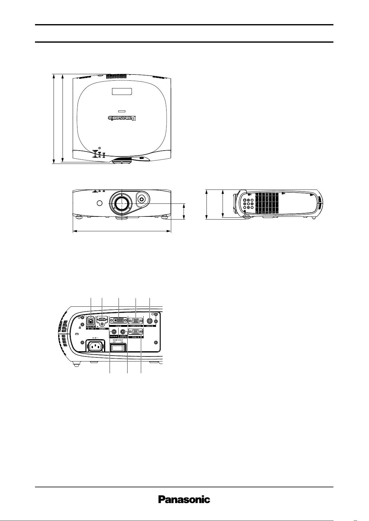
415 (16-11/32)
409 (16-3/32)
455 (17-29/32)
128.5
137
72
(5-1/16)
(5-13/32)
(2-27/32)
S P E C F I L E
1
678
23 45
DLP™Projectors
Dimensi ons
P T-RW330
uni t : m m (in ch)
NOT E: This il lu str at io n is not dra wn to sc al e.
Terminals
1 LAN / DIGITAL LINK c onn ector
2 HDMI input
3 DVI- I in put
4 Comp ute r input
5 Video i npu t
6 Audi o in put
7 Audi o ou tpu t
8 Seri al inp ut
As of January 2013
SFD12M 010 -2
4 / 1 2
Page 5

S P E C F I L E
Upper edge of projected image
197
(7-3/4)
218
(8-19/32)
*
Lower edge of projected image
Projected image
L
L
L
339–419
(13-11/32 –
16-1/2)
402.5–482.5
(15-27/32 – 19)
100
(3-15/16)
344
(13-17/32)
100
(3-15/16)
300
(11-13/16)
Projected image
HH
∅ 60.5
(∅ 2-3/8)
1.02
1.27
1.52
1.78
2.03
2.29
2.54
3.05
3.81
5.08
6.35
7.62
1.3
1.6
2.0
2.3
2.6
3.0
3.3
4.0
5.0
6.7
8.3
10.0
2.6
3.3
4.0
4.6
5.3
6.0
6.7
8.0
10.0
13.4
16.7
20.1
-0.10
-0.13
-0.15
-0.18
-0.21
-0.23
-0.26
-0.31
-0.38
-0.51
-0.64
-0.77
0.52
0.65
0.78
0.91
1.03
1.16
1.29
1.55
1.94
2.59
3.23
3.88
−
−
−
−
−
−
−
−
−
−
−
−
40
50
60
70
80
90
100
120
150
200
250
300
/
/
/
/
/
/
/
/
/
/
/
/
(4.2)
(5.3)
(6.4)
(7.5)
(8.6)
(9.7)
(10.9)
(13.1)
(16.4)
(21.9)
(27.4)
(32.9)
(8.7)
(10.9)
(13.1)
(15.3)
(17.5)
(19.6)
(21.8)
(26.2)
(32.8)
(43.8)
(54.8)
(65.8)
(-0.3
(-0.4
(-0.5
(-0.6
(-0.7
(-0.8
(-0.8
(-1.0
(-1.3
(-1.7
(-2.1
(-2.5
1.7)
2.1)
2.5)
3.0)
3.4)
3.8)
4.2)
5.1)
6.4)
8.5)
10.6)
12.7)
−
−
−
−
−
−
−
−
−
−
−
−
Projection size
[diagonal]
[m] [in]
Projection distance [L]
Min [wide] Max [telephoto]
Height from the edge of screen
to center of lens [H ]
DLP™Projectors
Standard s ett ing-up posit ion
P T-RW330
NOT E:
Ill us tr ati on s sho w the pro je cto r ins ta lle d
usi ng opti ona l cei li ng mou nt brac ket
ET-PK R1 00H .
Thi s ill us tra ti on is not dra wn to sca le .
Adj us ta ble in 40 mm (1-9 /1 6 in) ste ps .
*
uni t : m m (in ch)
C a u t io n :
• All c on struction work should be done by a qualified technician.
• When mounting to the ceiling, use the ceiling mount bracket . Also, t o prevent the pro je ctor from d ropping, be
sure to attach the wire that is i nc lu ded with the ceiling mount bracket.
Proj ection dista nce for 16:10 aspec t ra tio scree n
NOT E:
• The val ue for L (dis tan ce to scree n) vari es sli gh tly with in ±5 % dep end in g on the zo om le ns ch aract er istic s.
• The zoo m len s cha rac te ri sti cs may cau se sli gh t image dis to rti on .
• When vert ic al key st on e corr ec tio n is use d, th e ima ge is cor recte d in the di rec tion tha t red uce s its proje ct ed si ze .
• The bri gh tn ess vari es de pe ndi ng on the zoom sett in g.
As of January 2013
SFD12M 010 -2
uni t: mete rs (fe et )
5 / 1 2
Page 6

S P E C F I L E
1.02
1.27
1.52
1.78
2.03
2.29
2.54
3.05
3.81
5.08
6.35
7.62
1.3
1.7
2.0
2.4
2.7
3.1
3.4
4.1
5.1
6.9
8.6
10.3
2.7
3.4
4.1
4.8
5.5
6.2
6.8
8.2
10.3
13.7
17.2
20.6
-0.05
-0.06
-0.08
-0.09
-0.10
-0.11
-0.13
-0.15
-0.19
-0.25
-0.31
-0.37
0.48
0.60
0.71
0.83
0.95
1.07
1.19
1.43
1.79
2.38
2.98
3.57
−
−
−
−
−
−
−
−
−
−
−
−
40
50
60
70
80
90
100
120
150
200
250
300
/
/
/
/
/
/
/
/
/
/
/
/
(4.4)
(5.5)
(6.6)
(7.8)
(8.9)
(10.0)
(11.2)
(13.5)
(16.9)
(22.5)
(28.2)
(33.9)
(8.9)
(11.2)
(13.4)
(15.7)
(17.9)
(20.2)
(22.4)
(27.0)
(33.7)
(45.0)
(56.3)
(67.6)
(-0.2
(-0.2
(-0.2
(-0.3
(-0.3
(-0.4
(-0.4
(-0.5
(-0.6
(-0.8
(-1.0
(-1.2
1.6)
2.0)
2.3)
2.7)
3.1)
3.5)
3.9)
4.7)
5.9)
7.8)
9.8)
11.7)
−
−
−
−
−
−
−
−
−
−
−
−
Projection size
[diagonal]
[m] [in]
Projection distance [L]
Min [wide] Max [telephoto]
Height from the edge of screen
to center of lens [H ]
DLP™Projectors
P T-RW330
Proj ection dista nce for 16:9 a spe ct ratio screen
uni t: mete rs (fe et )
NOT E:
• The val ue for L (dis tan ce to scree n) vari es sli gh tly with in ±5 % dep end in g on the zo om le ns ch ar act er istic s.
• The zoo m len s cha rac te ri sti cs may cau se sli gh t image dis to rti on .
• When vert ic al key st on e corr ec tio n is use d, th e ima ge is cor recte d in the direc ti on tha t red uce s its proje ct ed si ze .
• The bri gh tn ess vari es de pe ndi ng on the zoom sett in g.
Calculat ion of the proje ction dista nce
For a screen siz e di fferent from the above , us e the equatio n be low to calculate th e project ion distance.
NOT E:
Dis ta nc es cal cu la ted with the abo ve equ at ions wil l inc lud e a slig ht er ror.
As of January 2013
SFD12M 010 -2
Aspect rat io 16:10
minimum L (m) = ( dia gonal screen s ize in inc hes) × 0.033 6 – 0 .05 42
maximum L (m) = ( diagonal screen s ize in inches) × 0.0670 – 0.0407
Aspect rat io 16:9
minimum L (m) = ( dia gonal screen s ize in inc hes) × 0.034 6 – 0 .05 42
maximum L (m) = ( diagonal screen s ize in inches) × 0.0688 – 0.0407
6 / 1 2
Page 7

S P E C F I L E
H
(Width of
projected image)
V
(Height of
projected image)
0.69V0.46V
0.37H0.28H
Standard postition
of projected image
H
(Width of
projected image)
V
(Height of
projected image)
0.46V0.69V
0.28H0.37H
Standard postition
of projected image
360°
-15°
+15°
DLP™Projectors
P T-RW330
Shift range
Optical axis shift function allows to shift the posit ion of a proj ected image as shown bel ow.
• Floor mount • Ceiling mou nt
Install abl e an gle
Install the proj ect or at an angle withi n th e range shown below.
• Vertical directio n
The p rojec tor may be installed at a v ertical
angle of 360°.
• Horizont al direc tio n
The p rojec tor may be installed at a h orizonta l
angle of ±15°.
As of January 2013
SFD12M 010 -2
7 / 1 2
Page 8

S P E C F I L E
Display mode Display
resolution
(dots)
Scanning frequency
H
(kHz)V(Hz)
Dot clock
frequency
(MHz)
Format
720 × 480i
720 × 576i
720 × 480i
720 × 576i
720 × 483
720 × 576
1,280 × 720
1,920 × 1,035i
1,920 × 1,080i
1,920 × 1,080
1,920 × 1,080i
1,920 × 1,080
640 × 400
640 × 480
800 × 600
832 × 624
1,024 × 768
1,152 × 864
1,152 × 870
1,280 × 720
1,280 × 768
1,280 × 800
1,280 × 960
1,280 × 1,024
1,400 × 1,050
1,440 × 900
1,600 × 1,200
1,680 × 1,050
1,920 × 1,080
1,920 × 1,200
15.7
15.6
15.7
15.6
31.5
31.3
45.0
37.5
33.8
33.8
28.1
27.0
27.0
28.1
33.8
67.5
56.3
31.5
37.9
31.5
35.0
37.5
37.9
43.3
35.2
37.9
48.1
46.9
53.7
49.7
39.6
48.4
56.5
60.0
65.5
68.7
80.0
99.0
64.0
67.5
77.1
68.7
37.1
44.8
39.6
47.8
41.3
49.7
55.9
64.0
80.0
91.1
65.2
65.3
82.2
60.0
75.0
65.3
66.6
74.0
59.9
50.0
59.9
50.0
59.9
50.0
60.0
50.0
60.0
60.0
50.0
24.0
24.0
25.0
30.0
60.0
50.0
70.1
85.1
59.9
66.7
75.0
72.8
85.0
56.3
60.3
72.2
75.0
85.1
74.6
50.0
60.0
70.1
75.0
81.6
85.0
100.0
119.8
70.0
74.9
85.0
75.1
49.8
59.9
49.9
59.9
50.0
59.8
59.9
60.0
75.0
85.0
60.0
60.0
75.0
60.0
60.0
60.0
59.9
60.0
−
−
13.5
13.5
27.0
27.0
74.3
74.3
74.3
74.3
74.3
74.3
74.3
74.3
74.3
148.5
148.5
25.2
31.5
25.2
30.2
31.5
31.5
36.0
36.0
40.0
50.0
49.5
56.3
57.3
51.9
65.0
75.0
78.8
86.0
94.5
105.0
137.8
94.2
108.0
119.7
100.0
60.5
74.5
65.3
79.5
68.0
83.5
106.5
108.0
135.0
157.5
122.6
121.8
155.9
108.0
162.0
146.3
138.5
154.0
NTSC/NTSC4.43/PAL-M/PAL60
PAL/PAL-N/SECAM
480i (525i)
576i (625i)
480p (525p)
576p (625p)
720 (750)p/60p
720 (750)p/50p
1035 (1125)/60i
1080 (1125)/60i
1080 (1125)/50i
1080 (1125)/24p
1080 (1125)/24sF
1080 (1125)/25p
1080 (1125)/30p
1080 (1125)/60p
1080 (1125)/50p
VGA400
VGA
SVGA
MAC16
XGA
MXGA
MAC21
1280 × 720
1280 × 768
1280 × 800
MSXGA
SXGA
SXGA+
WXGA+
UXGA
WSXGA+
1920 × 1080
WUXGA
VIDEO/S-VIDEO
YP
BP R/
COMPUTER (RGB)
HDMI/DVI/
COMPUTER (RGB)/
YP
BP R
HDMI/DVI/
COMPUTER (RGB)
*
1
*
2
*
2
DLP™Projectors
List of compa tib le signals
The s ign als that c an be inp ut to this p rojec tor are sh own in the table below. Horiz ontal scann ing frequencie s of 15 kHz to 100 kHz, ve rti cal scanning frequen cies of 24 H z to 120 Hz, and a dot clock of
162 MHz m axi mum can be input .
NOT E: T he nat iv e reso lu ti on of thi s projec to r is 1,28 0 × 800 pixel s. If th e dis pla y res olu ti on of the inp ut sig na l is diff erent from the
nat iv e reso lu ti on, imag e com pre ss ion or expa ns ion will be used to con ve rt th e inp ut sig na l to a leve l with in the nati ve resol ut io n.
1. The “i” app ea rin g aft er th e reso lu ti on ind ic ates an int er laced sign al.
2. Com pl ia nt wit h VES A CVT-RB (Coo rdi na ted Vide o Timi ng -R edu ce d Bla nki ng ).
As of January 2013
SFD12M 010 -2
P T-RW330
8 / 1 2
Page 9

S P E C F I L E
6
15
9
Start
(1 byte)
End
(1 byte)
Colon
(1 byte)
Semicolon
(1 byte)
(2 byte)
ID designator
01 to 64: Address number
0A to 0Z: Group ID
ZZ: All units (ID ALL)
ID: 2 characters
(2 bytes)
Parameters
(undefined length)
Command
(3 bytes)
(Control and/or query commands)
STX ETXC1P1P2...PnC2A DI1I2 C3: ;
DLP™Projectors
P T-RW330
Serial con nec tor
The s eri al connector co mpl ies with R S-2 32C. To c ontro l th e proj ector from a personal compu ter, c ommands must be inp ut throu gh communic ati on software, b ase d on the format and satis fying the communicatio n co nditions shown below.
Pin a ssi gnments a nd signal names
Desc ri ption
NC
Send da ta
Rece iv e d at a
Conn ec ted i ntern ally
Ground
No.
6
7
8
9
Sign al name
–
CTS
RTS
–
Desc ri ption
NC
Conn ec ted i ntern ally
Conn ec ted i ntern ally
NC
D-s ub 9-pi n (fem al e) Se ri al inp ut
No.
1
2
3
4
5
Sign al name
–
TXD
RXD
–
GND
Communi cat ion conditio ns (fa ctory setti ng)
Sign al level
Sync hr on ization method
Baud ra te
Pari ty
Char ac ter l ength
Stop bi t
X param et er
S param et er
RS-2 32 C-com pl iant
Star t- stop syn ch ro nizatio n
9,60 0 bps
None
8 bits
1 bit
None
None
Basic forma t
Tran smi ssion from the computer begin s with STX, t hen the ID, command, parameter, and ET X are sen t
in this o rder. Add paramete rs acc ordin g to the details o f co ntrol .
CAU TION
• It may not be possibl e that re spons es wo uld dela y or comma nds canno t be execu ted when co mma nds are sent soon after the
lig ht so urc e is turned on. If this oc curs, wait for 60 seconds , then tr y sending or recei ving agai n.
• Wh en se nding mult iple comm ands, be sure to wait for at leas t 0.5 second after receivi ng a resp onse from th e project or be fore
sen ding the next comma nd.
• Ad ditio nal time is sometim es requi red for resp onse due to proce ssing insi de th e project or. Set the time -ou t peri od fo r comman d respons e to 10 secon ds or more .
• Wh en us ing two or more un its, set diff ere nt ID s for each unit .
As of January 2013
SFD12M 010 -2
9 / 1 2
Page 10

S P E C F I L E
Command : Parameter Function Callback
PON
POF
IIS:DL1
IIS:HD1
IIS:DVI
IIS:RG1
IIS:VID
IIS: DL1:HD1
IIS: DL1:HD2
IIS: DL1:PC1
IIS: DL1:PC2
IIS: DL1:VID
IIS: DL1:SVD
OSH:0
OSH:1
OFZ:0
OFZ:1
OAS
OLP:*
OLP:*
OLP:*
OLP:*
VPM:NAT
VPM:STD
VPM:DYN
VPM:CIN
VPM:GRA
VPM:DIC
VPM:709
OTE:1
OTE:2
OTE:4
OTE:10
TSD:y1y2y3y4m1m2d1d2w
TST:h1h2m1m2s1s2
OOS:0
OOS:1
POWER (STANDBY)
INPUT SELECT
AV MUTE
FREEZE
AUTO SETUP
LIGHT SOURCE POWER
PICTURE MODE
COLOR TEMPERATURE
DATE
TIME
ON SCREEN
PON
POF
IIS:DL1
IIS:HD1
IIS:DVI
IIS:RG1
IIS:VID
IIS:DL1:HD1
IIS:DL1:HD2
IIS:DL1:PC1
IIS:DL1:PC2
IIS:DL1:VID
IIS:DL1:SVD
OSH:0
OSH:1
OFZ:0
OFZ:1
OAS
OLP:0
OLP:6
OLP:7
OLP:1
VPM:NAT
VPM:STD
VPM:DYN
VPM:CIN
VPM:GRA
VPM:DIC
VPM:709
OTE:1
OTE:2
OTE:4
OTE:10
TSD:y1y2y3y4m1m2d1d2w
TST:h1h2m1m2s1s2
OOS:0
OOS:1
On
Off
DIGITAL LINK
HDMI
DVI
COMPUTER
VIDEO
HDMI 1
HDMI 2
COMPUTER 1
COMPUTER 2
VIDEO
S-VIDEO
Off
On
Off
On
Normal
Eco Save 1
Eco Save 2
Low
Natural
Standard
Dynamic
Cinema
Graphic
DICOM
Rec. 709
Middle
High
User
Default
Date setting
Time setting
On-screen display off
On-screen display on
When DIGITAL LINK input is
selected and input of the
digital interface box
ET-YFB100G is changed
as well.
1
2
3
4
5
6
7
8
9
1
2
3
4
5
6
7
8
9
PC (DTE)Projector
NC
NC
NC
NC
NC
NC
NC
NC
DLP™Projectors
Cable speci fic ations
Control commands
P T-RW330
* Whe n a comm an d that cann ot be exec ute d dur in g stan db y mode is sent , the pr oje ct or wi ll se nd an ER401 comm an d in repl y.
As of January 2013
SFD12M 010 -2
1 0 / 1 2
Page 11

S P E C F I L E
Command: Parameter Function DescriptionCallback
QPW
QIN
QSH
QFZ
QOS
QST
QLP
QPM
QTM:0
QTM:2
QTM:3
QTM:4
QTM:5
QTM:6
QGD
QGT
Standby power status
Input signal status
Input signal status of the digital
interface box ET-YFB100G when
DIGITAL LINK input is selected.
AV mute status
Freeze function status
On-screen display status
Projector run time
Light source power mode status
Picture mode status
Temperature status
Date setting status
Time setting status
Off
On
DIGITAL LINK
HDMI
DVI
RGB 1
RGB 2
VIDEO
HDMI 1
HDMI 2
COMPUTER 1
COMPUTER 2
VIDEO
S-VIDEO
Off
On
Off
On
Off
On
00000h–99999h
Normal
Eco Save 1
Eco Save 2
Low
Natural
Standard
Dynamic
Cinema
Graphic
DICOM
Rec. 709
Intake
Optical module
Inside
Light source (Red)
Light source (Green)
Light source (Blue)
yyyymmdd (day of week)
(*2)
hhmmss
000
001
DL1
HD1
DVI
RG1
RG2
VID
DL1*HD1
DL1*HD2
DL1*PC1
DL1*PC2
DL1*VID
DL1*SVD
0
1
0
1
0
1
p1p2p3p4p5
OLP:0
OLP:6
OLP:7
OLP:1
NAT
STD
DYN
CIN
GRA
DIC
709
p1p2p3p4/p5p6p7p8
(*1)
y1y2y3y4m1m2d1d2w
h1h2m1m2s1s2
*
2
Day of week: Monday = 1, Tuesday = 2, ... Sunday = 7
*
1
p1p2p3p4: Celsius (°C), p5p6p7p8: Fahrenheit (°F)
ADZZ OOS :0; ETX
ID Add re ss Comm and
STX
Sta rt Par ame te r En d
DLP™Projectors
Status request com man ds
P T-RW330
NOT E: If a wro ng co mm and is rece ive d, the proj ec to r will send an ER401 or ER40 2 com man d to the comp ute r.
Command examp le
To set the on-screen displ ay off, sen d the command as shown bel ow.
NOT E: When se nd ing comm an ds wit ho ut pa ra met er s, a col on (: ) is not nec es sa ry.
As of January 2013
SFD12M 010 -2
1 1 / 1 2
Page 12

S P E C F I L E
500 mm (1 ft 8 in)
or more
500 mm (1 ft 8 in)
or more
500 mm (1 ft 8 in)
or more
Do not stack projector
units directly on top of
one another.
100 mm
(3-15/16 in)
or more
DLP™Projectors
P T-RW330
Notes on project or pla cement and opera tio n
Please obs erv e the following preca uti ons for projector p lacement and op era tion.
1. Never place obj ects on top of the projector whi le it is operating.
2. Make s ure th ere is an unobs tructed s pac e of 500 mm (1 feet 8 inche s) or more aroun d th e proj ec-
tor’s exhaust o penings.
3. Do not stack project or uni ts directly on top of one anoth er for the purpose of mul tiple (stacked )
projection. Whe n st acking projector uni ts, be sure to provi de the amount of space indicated b elo w
between them. These space requirements also apply to installa tio ns where only one projector unit
is operatin g at one time and the o the r unit is used a s a bac kup.
4. Make s ure th at not hing blocks the project or’s ai r in take and e xha ust openings . Al so, install t he pro-
jector so tha t co ol or hot air from other air condi tio ning equipme nt does not flow directly toward
the p rojec tor’s air int ake or exhaust ope nings.
5. Do not install the proje ctor in an enclosed space. If it is necessar y to install it in an enclo sed
space, add a s eparate ven til ation system. If ven tilation is insuffi cie nt, hot air will acc umu late a t th e
intake ope ning. This m ay cau se the projector’s protective circuit to interrupt p rojec tor operation.
6. If the projector is pla ced in a bo x, ensure that the projector’s intak e an d ex haust openi ngs are no t
blocked . Take par ticular care t o en sure tha t hot air from the exhaust ope nin gs is not sucked in to
the i nta ke openings .
7. To install and us e th e project or via a method t hat does not use the a dju stable feet in a fl oor sta nd-
ing i nst allation, fi x th e proj ect or using the four screw holes for ceiling m oun ting. (Screw d iam eter:
M4, t app ing depth insid e th e se t: 10 mm, torque: 1.25 ± 0. 2 N· m)
Dire ction of air intak e an d ex haust
Wei ght s and dime nsi on s sho wn are appro xi ma te. Spec ifica ti ons and app ea ran ce are subj ec t to cha nge with ou t noti ce .
Pro du ct ava il ab ili ty diffe rs depe ndi ng on regio n and country. This pr odu ct may be sub jec t to exp ort cont rol regu latio ns .
DLP an d the DLP log o are tra de mar ks of Tex as In st rum en ts .
PJL in k is a regis te red trad em ark , or a trad em ark appl ic ati on has been file d, in Ja pa n, the Unit ed St at es, and oth er co untri es and regi on s.
All othe r tra dem ar ks ar e the pro pe rty of thei r resp ec ti ve tra de mark own er s.
As of January 2013
SFD12M 010 -2
Int ak e
Exh au st
1 2 / 1 2
 Loading...