

Page 1
DLP™ Projector
PT-
RCQ80B/RCQ80LB/RCQ80W/RCQ80LW
Specifications
Main unit
Power supply AC 100V - 240V, 50Hz/60Hz
Power consumption 880 W (890VA)
NORMAL: 770W ECO: 590W SHUTTER: 100W
*Operating Temperature: 25 °C (77 °F), Altitude: 700m (2,297 ft),
IEC62087: 2008 Broadcast contents,
Picture mode: Standard, Dynamic Contrast2
STANDBY MODE [ECO]: 0.5W STANDBY MODE [NORMAL]: 8W
STANDBY MODE (When the [QUICK STARTUP] function is enabled): Approx. 100W
BTU value Max 3,003 BTU
DLP™ chip Panel size
Projection system
Pixels
Light source Laser Diode
Light output*
Time until light output declines to 50 %*
1
4
Resolution
Contrast*
2
Screen size
Center-to-corner uniformity*
Lens
2
PT-RCQ80B/W
PT-RCQ80LB/LW
Compatible signal
HDMI
DVI-D
SDI HD-SDI signal
DIGITAL LINK
DisplayPort*
*1 Value is for the supplied standard zoom lens. The value varies depending on the lens.
*2 Measurement, measuring conditions, and method of notation all comply with ISO/IEC 21118:2012 international standards.
*3 Average light-output value of all shipped products measured at center of screen in NORMAL Mode.
*4 Around this time, light output will have decreased by approximately 50 %. IEC62087: 2008 Broadcast contents, NORMAL Mode, Dynamic Contrast [3],
under conditions with 30 °C (86 °F), 700 m (2,297 ft) above sea level, and 0.15 mg/m
depending on environment.
*5 This is supported when the Interface Board for 12G-SDI input (Model No.: ET-MDN12G10) is installed in the slot.
*6 This is supported when the optional Interface Board for DisplayPort 2input (Model No.: ET-MDNDP10) is installed in the slot.
6
17.0 mm (0.67 in) diagonal (16:10 aspect ratio)
DLP™ chip × 1, DLP™ system
2,304,000 (1920 × 1200)
8,000 lm*
2
/ 8,400 lm(Center)*
3
(When [OPERATING MODE] is set to [NORMAL])
6,400 lm (When [OPERATING MODE] is set to [ECO])
6,400 lm (When [OPERATING MODE] is set to [QUIET])
20,000 hours (NORMAL)/24,000 hours (ECO)
4,608,000 pixels (2715x1697)
10,000:1 (All White/All Black) (Dynamic Contrast3)
1.27– 15.24 m (50– 600 inches) (16:10 aspect ratio)
*2.54– 10.15m (100– 400 inches) with ET-DLE020 (16:10aspect ratio)
*1.27– 5.08 m (50– 200 inches) with the ET-DLE055 (16:10 aspect ratio)
*2.54– 8.89 m (100– 350 inches) with the ET-DLE035 (16:10 aspect ratio)
90%
Powered zoom/focus lenses (1.7–2.4:1), F 1.7–1.9, f 25.6–35.7 mm
Optional powered zoom/focus lenses and xed-focus lens
Moving image signal resolution: 480/60p, 576/50p to 4096 × 2160
Still image signal resolution: 640 × 480 to 3840 × 2400 (non-interlace)
Dot clock frequency: 25 MHz to 594 MHz
Moving image signal resolution: 480/60p, 576/50p to 1920 × 1080
Still image signal resolution: 640 × 480 to 1920 × 1200 (non-interlace)
Dot clock frequency: 25 MHz to 162 MHz
3G-SDI signal
6G-SDI signal*
12G-SDI signal*
5
5
Moving image signal resolution: 480/60p, 576/50p to 4096 × 2160
Still image signal resolution: 640 × 480 to 1920 × 1200 (non-interlace)
Dot clock frequency: 25 MHz to 297 MHz
Moving image signal resolution: 720/60p to 4096 × 2160
Still image signal resolution: 640 × 480 to 3840 × 2400 (non-interlace)
Dot clock frequency: 25 MHz to 594 MHz
3
of particulate matter. Estimated time until light output declines to 50 % varies
As of October 2019 1/30
PT-RCQ80B/RCQ80LB/RCQ80W/RCQ80LWG_STE_01_31/10/2019
Page 2
DLP™ Projector
PT-
RCQ80B/RCQ80LB/RCQ80W/RCQ80LW
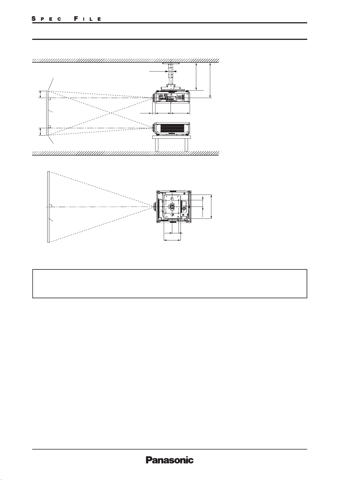
Geometry correction
range
[VERTICAL KEYSTONE] (viewed from the side) [HORIZONTAL KEYSTONE] (viewed from above)
Screen
Arc center
Screen
Screen
Projection distance
Arc radius
Screen
Vertical arc correction (viewed from the side) Horizontal arc correction (viewed from above)
Projection distance
Arc radius
Screen
Arc center
Screen
Projection distance
Arc radius
[KEYSTONE] and [CURVED] used together Only [CURVED] used
Vertical
keystone
correction
angle α (°)
±20
±20
±20
±20
±8
―
±8
±8
Horizontal
keystone
correction
angle β (°)
±8
―
±8
±8
±15
±15
±15
±15
Projection lens
Model No.
ET-DLE020
ET-DLE035*
ET-DLE055
ET-DLE060
ET-DLE085
ET-DLE105
ET-DLE150
ET-DLE170
ET-DLE250
ET-DLE350
ET-DLE450
Only [KEYSTONE] used
Vertical
keystone
correction
angle α (°)
±5 0 ― ― ― ― ― ―
6
+5/-0 0 ― ― ― ― ― ―
±22
±16
±22
±22
±40
Horizontal
keystone
correction
angle β (°)
±15
±10
±15
±15
±15
±40 ±15 ±20 ±15
±40
±40
±40
±15
±15
±15
When using the optional Upgrade Kit (Model No.: ET-UK20)
7
[KEYSTONE] and [CURVED] used together Only [CURVED] used
Vertical
keystone
correction
angle α (°)
±20
±20
±20
±20
―
±8
―
±8
±8
Horizontal
keystone
correction
angle β (°)
―
±8
―
±8
±8
±15
±15
±15
±15
Projection lens
Model No.
ET-DLE020
ET-DLE035*
ET-DLE055
ET-DLE060
ET-DLE085
ET-DLE105
ET-DLE150
ET-DLE170
ET-DLE250
ET-DLE350
ET-DLE450
Only [KEYSTONE] used*
Vertical
keystone
correction
angle α (°)
±5
6
+5/-0 0 ― ― ― ― ― ―
±22
±16
±22
±22
±40
Horizontal
keystone
correction
angle β (°)
0
±15
±10
±15
±15
±40
±40 ±40 ±20 ±15
±40
±45
±45
±40
±40
±40
Min. value
of R2/L2
1.7
―
1.7
1.7
1.1
0.9
0.7
0.4
0.3
Min. value
of R2/L2
―
1.3
―
1.3
1.3
0.9
0.7
0.5
0.3
0.2
Min. value
of R3/L3
4.3
―
4.3
4.3
2.6
1.7
1.3
0.8
0.6
Min. value
of R3/L3
―
3.3
―
3.3
3.3
2
1.3
1
0.6
0.4
Projection distance
Arc radius
Min. value
of R2/L2
1
―
1
1
0.6
0.5
0.4
0.3
0.2
Min. value
of R2/L2
―
0.8
―
0.8
0.8
0.5
0.4
0.3
0.2
0.2
Min. value
of R3/L3
2.6
―
2.6
2.6
1.5
1
0.7
0.5
0.3
Min. value
of R3/L3
―
1.9
―
1.9
1.9
1.1
0.7
0.6
0.4
0.3
As of October 2019 2/30
PT-RCQ80B/RCQ80LB/RCQ80W/RCQ80LWG_STE_01_31/10/2019
Page 3
DLP™ Projector
PT-
RCQ80B/RCQ80LB/RCQ80W/RCQ80LW
Lens shift
Installation
Terminals
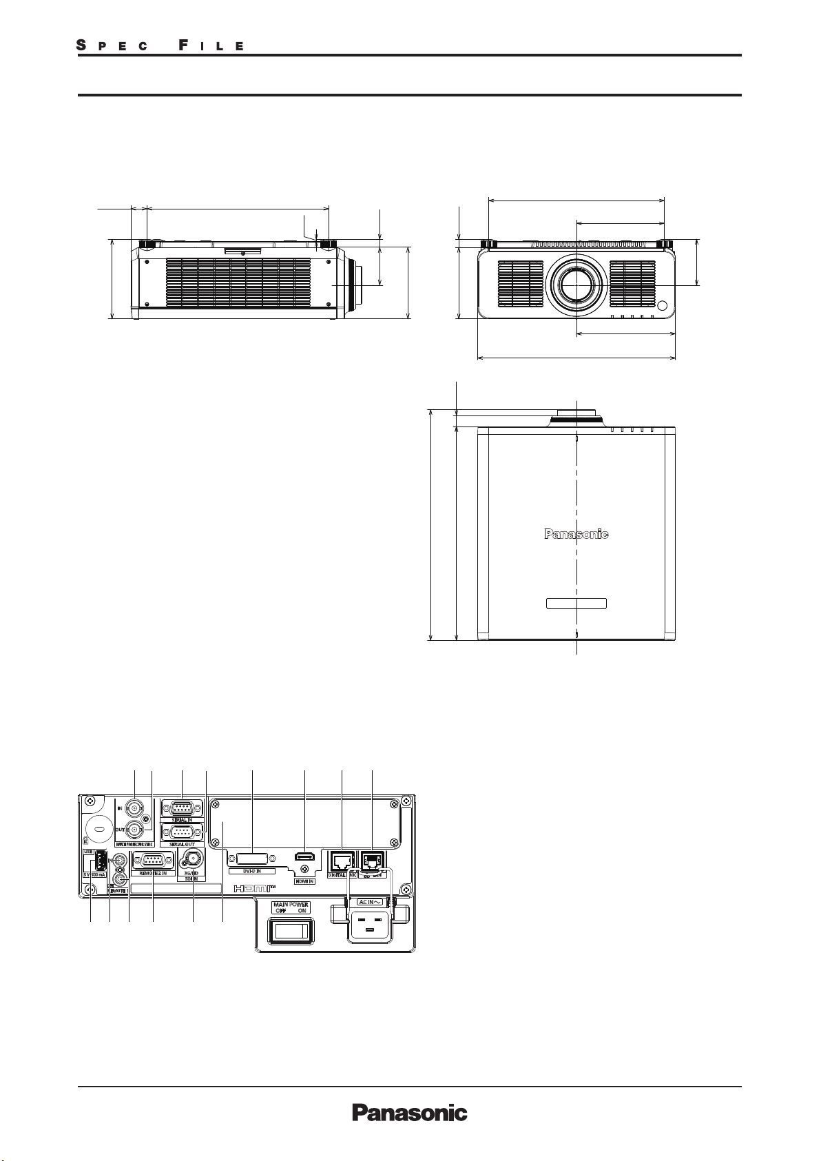
Dimensions
(W × H × D)*
Weight
Operation noise
Laser Classication Laser Class
Operating temperature
Operating humidity
8
DVI-D IN DVI-D 24-pin × 1, DVI 1.0 compliant, compatible with HDCP,
HDMI IN IN
SDI IN BNC × 1,
MULTI PROJECTOR
SYNC IN
MULTI PROJECTOR
SYNC OUT
SERIAL IN
SERIAL OUT
REMOTE 1 IN
REMOTE 1 OUT M3 jack × 1 for link control (for wired remote control)
REMOTE 2 IN
DIGITAL LINK/LAN
LAN RJ-45 × 1 for network connection, PJLink (class 2) compatible,
USB USB Type A × 1, for USB memory stick/Wireless Module (Option:AJ-WM50GT),
SLOT SLOT 1 (vacant) for interface boards, SLOT NX compatible
PT-RCQ80B/PT-RCQ80W
PT-RCQ80LB/PT-RCQ80LW
PT-RCQ80B/PT-RCQ80W
PT-RCQ80LB/PT-RCQ80LW
Risk Group
Vertical: +50%, -16%(powered)
(When using the ET-DLE060, +40%, -16%)
Horizontal: +30%, -10%(powered)
(When using the ET-DLE060, +19%, -10%)
(When using the ET-DLE085/ET-DLE105, +28%, -10%)
(When using the ET-DLE020, +10%, -20%)
NOTE: Lens shift function canno t b e operated when used with the ET-DLE055.
If using the ET-DLE035, the lens i s fixed.
Ceiling/oor, front/rear
for single link only
HDMI 19-pin × 1, Deep Color, compatible with HDCP2.2,
HD-SDI signal: SMPTE ST 292 compliant
3G-SDI signal: SMPTE ST 424, 425-2 compliant
BNC x 1 TTL Hi-z
BNC x 1 TTL max 10mA
D-sub 9-pin (female) × 1
D-sub 9-pin (male) × 1 for link control
M3 jack × 1 for wired remote control
D-sub 9-pin (female) × 1 for external control (parallel)
RJ-45 × 1 for network, DIGITAL LINK connection (HDBaseT™ compliant),
100Base-TX, compatible with Art-Net, PJLink™ (Class 2), eep Color,
HDCP 2.2
10Base-T/100Base-TX, Art-Net compatible
for power supply (DC5V, max 500mA)
3.0 m (9 ft10 in)Power cord length
Molded plasticCabinet materials
498 × 200 × 581 mm (19-19/32 × 7-7/8 × 22-7/8in) with lens
498 × 200 × 538 mm (19-19/32 × 7-7/8 × 21-3/16in) without lens
Approx. 24.2 kg (52.5 lbs.) with lens
Approx. 23.4 kg (51.6 lbs.) without lens
40 dB[NORMAL] /38 dB[QUIET]
USA and Canada: Class 3R (IEC 60825-1:2007)
Other countries or regions: Class 1 (IEC/EN 60825-1:2014)
ET-DLE020, ET-DLE035, ET-DLE055,
ET-DLE060, ET-DLE085, ET-DLE105,
ET-DLE150,
Standard zoom lens ET-DLE170
ET-DLE250, ET-DLE350, ET-DLE450 Risk Group 3 (IEC 62471-5:2015)
0–45 °C (32–113 °F)*
10%–80% (no condensation)
for external control (RS-232C compliant)
Risk Group 2 (IEC 62471-5:2015)
9
As of October 2019 3/30
PT-RCQ80B/RCQ80LB/RCQ80W/RCQ80LWG_STE_01_31/10/2019
Page 4
DLP™ Projector
Remote control unit
Power supply
Operation range
Dimensions (W × H × D)
10
Weight*
PT-
RCQ80B/RCQ80LB/RCQ80W/RCQ80LW
3 V DC (AAA/R03/LR03 battery × 2)
Approx. 30 m (98 ft5 in) when operated from directly in front of the
signal receptor
48 × 145 × 27 mm (1-7/8 × 5-23/32 × 1-1/16 in)
Approx. 102 g (3.6 ozs.) including batteries
Other Applications
Supplied accessories
Optional accessories
Digital interface box ET-YFB100G
Digital LINK Switcher ET-YFB200G
Zoom lens ET-DLE020
Zoom lens ET-DLE060
Zoom lens ET-DLE085
Zoom lens ET-DLE105
Zoom lens ET-DLE150
Zoom lens ET-DLE170
(same as supplied lens)
Zoom lens ET-DLE250
Zoom lens ET-DLE350
Zoom lens ET-DLE450
Fixed-focus lens ET-DLE035
Fixed-focus lens ET-DLE055
Multi Monitoring and Control Software (for Windows)
Logo Transfer Software (for Windows)
Geometry Manager Pro (for Windows)
Smart Projector Control (iOS/Android)
Power cord with secure lock (× 1) (× 2 for Europe / ASIA models)
Wireless/wired remote control unit (× 1)
Batteries for remote control (AAA/R03 or AAA/LR03 battery × 2)
Lens Mount Cover (× 1)
Lens cover (× 1) (Only models with lens)
Interface Board for DisplayPort ET-MDNDP10
DVI-D input signal board ET-MDNDV10
HDMI input signal board ET-MDNHM10
12G-SDI signal board ET-MDN12G10
Ceiling mount bracket ET-PKD120H (for high ceilings)
ET-PKD120S (for low ceilings)
High-ceiling mount bracket ET-PKD130H
(6-axis adjustment mechanism)
Attachment for ceiling mount bracket ET-PKD130B
Geometry Manager Pro Upgrade kit ET-UK20
Auto Screen Adjustment Upgrade kit ET-CUK10/CUK10P
Early Warning Software ET-SWA100*
11
Wireless Module AJ-WM50
NFC Upgrade Kit ET-NUK10*
11*12
*6 When [VERTICAL KEYSTONE] and [HORIZONTAL KEYSTONE] are used simultaneously, correction cannot be
made exceeding total of 55°.
• When [GEOMETRY] is used, the focus of the entire screen may be lost as correction increases.
• Make the curved screen a circular arc shape with one part of a perfect circle removed.
• Adjustment range of the [GEOMETRY] items may not match the listed projection range depending on the
projection lens. Use this projector within the projection range, otherwise the correction may not work.
*7 Only compatible with dot clock frequency of 27 MHz (pixel repetition signal).
*8 with legs at shortest position.
*9 Limits the luminance when used in locations from 0m to 2,700m (0ft to 8,858ft) above sea level at ambient temperatures of 30°C (86°F) or higher,
or from 2,700m to 4,200m (8,858ft to 13,780ft) above sea level at ambient temperatures of 25°C (77°F) or higher.
The projector’s operating environment temperature should be within 0 °C (32 °F) to 40 °C (104 °F) when the optional wireless module (Model No.: AJ-WM50) is attached.
*10 Average value. Weight varies for each product.
*11 The suffix will vary depending on the type of license.
*12 Availability may vary by country or region.
The optional NFC upgrade kit (Model No.:ET-NUK10) can be used to enable the NFC function of the projector. Note that there are some models that have
the NFC function enabled from the time of factory shipment, and there are some countries or regions where the NFC upgrade kit cannot be applied
For more information, visit :
As of October 2019 4/30
PT-RCQ80B/RCQ80LB/RCQ80W/RCQ80LWG_STE_01_31/10/2019
Page 5
DLP™ Projector
Dimensions
PT-
RCQ80B/RCQ80LB/RCQ80W/RCQ80LW
40.5
[1-19/32]
200
[7-7/8]
457
[18]
5
[3/16]
20
95.5
[25/32]
[3-3/4]
180
[7-3/32]
580.8
[22-7/8]
20.5
[13/16]
179.5
[7-1/16]
28
[1 3/32]
538
[21-3/16]
442
[17-13/32]
498
[19-19/32]
221
[8-11/16]
249
[9-13/16]
115.5
[4-9/16]
Terminals
unit : mm (inch)
NOTE : T his ill ustration i s not drawn to scale.
1211109 14
13
1
87654321
MULTI PROJECTOR SYNC INPUT
2
MULTI PROJECTOR SYNC OUTPUT
3
SERIAL INPUT
4
SERIAL OUTPUT
5
DVI-D INPUT
6
HDMI INPUT
7
DIGITAL LINK
8
LAN
9
USB
10
REMOTE 1 INPUT
11
REMOTE 1 OUTPUT
12
REMOTE 2 INPUT
13
SDI INPUT
14
Slot Cover
As of October 2019 5/30
PT-RCQ80B/RCQ80LB/RCQ80W/RCQ80LWG_STE_01_31/10/2019
Page 6
DLP™ Projector
PT-
RCQ80B/RCQ80LB/RCQ80W/RCQ80LW
Standard setting-up position (If using other than the ET-DLE035)
ø60. 5
Upper edge of pr ojected image
L
1
*
E E
294244
(11- 9/16)(9 -19/32)
*1 When the lens protrudes to the maximum.
2
*
352–432
(1 3-27/ 32–1 7)
269 mm (10-19/32 in) with the ET-DLE020
2
104 mm (4-3/32 in) with the ET-DLE060
84 mm (3-5/16 in) with the ET-DLE085
88 mm (3-15/32 in) with the ET-DLE105
44 mm (1-23/32 in) with the ET-DLE150
43 mm (1-11/16 in)
with the ET-DLE170
463.5–543. 5*
45 mm (1-25/32 in) with the ET-DLE250
(18- 1/4–21-13/ 32)
51mm (2 in) with the ET-DLE350
95 mm (3-3/4 in) with the ET-DLE450
27 mm (1-1/16 in) with the ET-DLE055
*2 Adjustable in 40 mm (1-9/16 in) steps.
Lower edge of projected i mage
370
100
Projected image
100
(3-15/1 6)
259
(10- 3/16)
(14- 9/16)
(3 -15/16)
NOT E:
Illustrations show the pro jector
installe d using optional ceiling mo unt
bracket ET-PKD120H , optional bracket
assembly ET-PKD130B and an op tional lens.
Thi s illustrati on is not drawn to scal e.
Cauti on:
•
All construction work should be don e by a qualied technician.
•
When mounting to the ceiling, use the special m ountin g bracket. Furthermore , in order to prevent it from falling
down from the ceiling, use the supplied w ir e on the moun ting bracket.
unit : mm (inch)
As of October 2019 6/30
PT-RCQ80B/RCQ80LB/RCQ80W/RCQ80LWG_STE_01_31/10/2019
Page 7

DLP™ Projector
PT-
RCQ80B/RCQ80LB/RCQ80W/RCQ80LW
Projection distance for 16:10 aspect ratio screen (If using other than the ET-DLE035)
Distance to screen (L )
Screen
size
(diagonal)
[m] [in]
1.27 / 50
1.52 / 60
1.78 / 70
2.03 / 80
2.29 / 90
2.54 / 100
3.05 / 120
3.81 / 150
5.08 / 200
6.35 / 250
7.62 / 300
8.89 / 350
10.16 / 400
12.70 / 500
15.24 / 600
ET-DLE020
Zoom lens
0.280-0.299:1
min. max.
-
-
-
-
-
-
-
-
-
-
0.59
0.64
0.72
0.77
0.90
0.97
1.21
1.30
1.52
1.63
1.83
1.96
2.14
2.29
2.45
2.63
-
-
-
-
ET-DLE060
Zoom lens
ET-DLE085
Zoom lens
ET-DLE105
Zoom lens
0.600-0.801:1 0.782-0.977:1 0.978-1.32:1 1.30-1.89:1 1.71-2.41:1 2.27-3.62:1 3.58-5.45:1 5.36-8.58:1
0.84
0.63
0.76
0.90
1.03
1.17
1.31
1.58
1.99
2.67
3.35
4.03
4.71
5.39
6.75
8.11
1.02
1.20
1.38
1.56
1.74
2.10
2.63
3.53
4.42
5.32
6.21
7.11
8.90
10.69
0.82
1.00
1.17
1.35
1.52
1.70
2.05
2.57
3.44
4.31
5.18
6.06
6.93
8.67
10.42
1.04
1.25
1.47
1.68
1.90
2.11
2.55
3.19
4.27
5.35
6.43
7.51
8.59
10.75
12.91
1.03
1.25
1.47
1.68
1.90
2.12
2.55
3.20
4.29
5.37
6.46
7.54
8.63
10.80
12.97
Zoom
ET-DLE150
Zoom lens
Standard
ET-DLE170
Zoom lens
Throw ratio
2.01
2.43
2.84
3.25
3.66
4.08
4.90
6.14
8.20
10.26
12.33
14.39
16.45
20.58
24.70
min. max.
1.82
2.20
2.58
2.95
3.33
3.71
4.47
5.60
7.50
9.39
11.28
13.18
15.07
18.86
22.64
min. max.min. max.mi n. max.min. max. min. max.min. max.min. max.
1.38
1.41
1.66
1.70
1.95
1.99
2.23
2.28
2.52
2.57
2.81
2.86
3.38
3.44
4.24
4.32
5.67
5.77
7.10
7.23
8.53
8.68
9.96
10.14
11.39
11.59
14.25
14.50
17.11
17.41
2.57
3.10
3.63
4.16
4.69
5.21
6.27
7.86
10.50
13.14
15.79
18.43
21.07
26.36
31.65
ET-DLE250
Zoom lens
2.42
2.92
3.42
3.92
4.42
4.92
5.91
11.75
7.41
15.70
9.91
19.64
12.41
23.59
14.91
27.53
17.40
31.48
19.90
39.37
24.90
47.25
29.89
3.87
4.65
5.44
6.23
7.02
7.81
9.39
ET-DLE350
Zoom lens
3.80
4.59
5.38
6.16
10.57
6.95
11.76
7.74
14.14
9.31
17.71
11.68
23.66
15.61
29.61
19.55
35.56
23.49
41.51
27.42
47.46
31.36
59.36
39.23
71.25
47.11
5.81
7.00
8.19
9.38
ET-DLE450
Zoom lens
5.66
6.85
11.01
8.04
12.89
9.23
14.78
10.43
16.66
11.62
18.55
14.00
22.31
17.58
27.97
23.54
37.39
29.50
46.81
35.46
56.24
41.42
65.66
47.38
75.08
59.30
93.93
112.77
71.22
9.12
Fixed-focus
ET-DLE055
Fixed-
focus lens
0.785:1
0.83
1.00
1.18
1.35
1.53
1.70
2.05
2.58
3.45
-
-
-
-
-
-
Unit: meters
Height from the edge of
screen to center of lens
(E)
ETDLE085
105/150
170/250
350/450
0−0.44
0−0.53
0−0.62
0−0.71
0−0.80
0−0.89
0−1.07
0−1.33
0−1.78
0−2.22
0−2.67
0−3.11
0−3.55
0−4.44
0−5.33
ET-
DLE060
0.07−0.44
0.08−0.53
0.09−0.62
0.11−0.71
0.12−0.80
0.13−0.89
0.16−1.07
0.20−1.33
0.27−1.78
0.34−2.22
0.40−2.67
0.47−3.11
0.54−3.55
0.67−4.44
0.81−5.33
ET-
DLE020
-
-
-
-
-
0−0.89
0−1.07
0−1.33
0−1.78
0−2.22
0−2.67
0−3.11
0−3.55
-
-
ET-
DLE055
0.34
0.40
0.47
0.54
0.61
0.67
0.81
1.01
1.35
-
-
-
-
-
-
Screen
size
(diagonal)
[m] [in]
1.27 / 50
1.52 / 60
1.78 / 70
2.03 / 80
2.29 / 90
2.54 / 100
3.05 / 120
3.81 / 150
5.08 / 200
6.35 / 250
7.62 / 300
8.89 / 350
10.16 / 400
12.70 / 500
15.24 / 600
ET-DLE020
Zoom lens
0.280 - 0.299:1
min. max.
-
-
-
-
-
-
-
-
-
-
1.94
2.10
2.36
2.53
2.95
3.18
3.97
4.27
4.99
5.35
6.00
6.43
7.02
7.51
8.04
8.63
-
-
-
-
ET-DLE060
Zoom lens
0.600-0.801:1
2.8
2.1
3.4
2.5
3.9
2.9
4.5
3.4
5.1
3.8
5.7
4.3
6.9
5.2
8.6
6.5
11.6
8.7
14.5
11.0
17.4
13.2
20.4
15.4
23.3
17.7
29.2
22.1
35.1
26.6
Distance to screen (L )
Zoom
ET-DLE085
Zoom lens
ET-DLE105
Zoom lens
ET-DLE150
Zoom lens
Standard
ET-DLE170
Zoom lens
ET-DLE250
Zoom lens
ET-DLE350
Zoom lens
ET-DLE450
Zoom lens
Throw ratio
0.782-0.977:1 0.978-1.32:1 1.30-1.89:1 1.71-2.41:1 2.27-3.62:1 3.58-5.45:1 5.36-8.58:1
2.7
3.3
3.9
4.4
5.0
5.6
6.7
8.4
11.3
14.1
17.0
19.9
22.7
28.5
34.2
3.4
4.1
4.8
5.5
6.2
6.9
8.4
10.5
14.0
17.6
21.1
24.6
28.2
35.3
42.3
3.4
4.1
4.8
5.5
6.2
7.0
8.4
10.5
14.1
17.6
21.2
24.8
28.3
35.4
42.5
min. max.min. max.mi n. max.min. max. min. max.min. max.min. max.
4.5
4.6
5.5
5.6
6.4
6.5
7.3
7.5
8.3
8.4
9.2
9.4
11.1
11.3
13.9
14.2
18.6
18.9
23.3
23.7
28.0
28.5
32.7
33.3
37.4
38.0
46.7
47.6
56.1
57.1
6.6
8.0
9.3
10.7
12.0
13.4
16.1
20.1
26.9
33.7
40.4
47.2
54.0
67.5
81.1
min. max.
6.0
10.2
7.2
11.9
8.5
13.6
9.7
15.4
10.9
17.1
12.2
20.6
14.7
25.8
18.4
34.5
24.6
43.1
30.8
51.8
37.0
60.5
43.2
69.1
49.4
86.5
61.9
103.8
74.3
8.4
29.9
18.6
19.1
12.5
12.7
7.9
36.1
22.5
23.0
15.1
15.3
9.6
42.3
26.4
26.9
17.6
17.9
11.2
48.5
30.3
30.8
20.2
20.4
12.8
54.7
34.2
34.7
22.8
23.0
14.5
60.8
38.1
38.6
25.4
25.6
16.1
73.2
45.9
46.4
30.6
30.8
19.4
91.8
57.7
58.1
38.3
38.6
24.3
122.7
77.2
77.6
51.2
51.5
32.5
153.6
96.8
97.1
64.1
64.4
40.7
184.5
116.3
116.7
77.1
77.4
48.9
215.4
135.9
136.2
90.0
90.3
57.1
246.3
155.4
155.7
102.9
103.3
65.3
308.2
194.6
194.7
128.7
129.2
81.7
370.0
233.7
233.8
154.6
155.0
98.1
Fixed-focus
ET-DLE055
Fixed-
focus lens
0.785:1
2.7
3.3
3.9
4.4
5.0
5.6
6.7
8.5
11.3
-
-
-
-
---
Unit: feet
Height from the edge of
screen to center of lens
(E)
ETDLE085
105/150
170/250
350/450
0−1.5
0−1.7
0−2.0
0−2.3
0−2.6
0−2.9
0−3.5
0−4.4
0−5.8
0−7.3
0−8.7
0−10.2
0−11.7
0−14.6
0−17.5
ET-
DLE060
0.2−1.5
0.3−1.7
0.3−2.0
0.4−2.3
0.4−2.6
0.4−2.9
0.5−3.5
0.7−4.4
0.9−5.8
1.1−7.3
1.3−8.7
1.5−10.2
1.8−11.7
2.2−14.6
2.6−17.5
ET-
DLE020
-
-
-
-
-
0−2.9
0−3.5
0−4.4
0−5.8
0−7.3
0−8.7
0−10.2
0−11.7
-
ET-
DLE055
1.1
1.3
1.5
1.8
2.0
2.2
2.6
3.3
4.4
-
-
-
-
-
-
• T he value for L (distance to screen) varies slightly within ±5% dep ending on the zoom lens characteristics.
• T he zoom lens characteristics may cause slight image distortion.
• W hen using keystone correction is used, the image is corrected in the d irectio n that red uces its projected size.
• T he brightness varies depending on the zoom setting.
Note: When the ET-DLE0 55 is mounted, the opti cal lens shift function cannot be used.
As of October 2019 7/30
PT-RCQ80B/RCQ80LB/RCQ80W/RCQ80LWG_STE_01_31/10/2019
Page 8
DLP™ Projector
PT-
RCQ80B/RCQ80LB/RCQ80W/RCQ80LW
Projection distance for 16:9 aspect ratio screen (If using other than the ET-DLE035)
Distance to screen (L )
Screen
size
(diagonal)
[m] [in]
1.27 / 50
1.52 / 60
1.78 / 70
2.03 / 80
2.29 / 90
2.54 / 100
3.05 / 120
3.81 / 150
5.08 / 200
6.35 / 250
7.62 / 300
8.89 / 350
10.16 / 400
12.70 / 500
15.24 / 600
ET-DLE020
Zoom lens
0.280-0.299:1
min. max.
-
-
-
-
-
-
-
-
-
-
0.65
0.61
0.79
0.74
0.99
0.93
1.34
1.25
1.68
1.56
2.02
1.88
2.36
2.20
2.70
2.52
-
-
-
-
ET-DLE060
Zoom lens
ET-DLE085
Zoom lens
ET-DLE105
Zoom lens
0.600-0.802:1 0.783-0.977:1 0.979-1.32:1 1.30-1.89:1 1.72-2.41:1 2.27-3.62:1 3.58-5.45:1 5.36-8.58:1
0.87
0.64
0.78
0.92
1.06
1.20
1.34
1.62
2.04
2.74
3.44
4.14
4.84
5.54
6.93
8.33
1.05
1.24
1.42
1.60
1.79
2.16
2.71
3.63
4.55
5.47
6.39
7.31
9.15
10.99
0.85
1.03
1.21
1.39
1.57
1.75
2.10
2.64
3.54
4.43
5.33
6.23
7.12
8.91
10.71
1.07
1.29
1.51
1.73
1.95
2.17
2.62
3.28
4.39
5.50
6.61
7.72
8.83
11.05
13.27
1.06
1.29
1.51
1.73
1.96
2.18
2.63
3.29
4.41
5.52
6.64
7.76
8.87
11.10
13.33
Zoom
ET-DLE150
Zoom lens
Standard
ET-DLE170
Zoom lens
Throw ratio
2.07
2.49
2.92
3.34
3.77
4.19
5.04
6.31
8.43
10.55
12.67
14.79
16.91
21.15
25.39
min. max.
1.87
2.26
2.65
3.04
3.43
3.82
4.60
5.76
7.71
9.65
11.60
13.55
15.49
19.38
23.27
min. max.min. max.mi n. max.min. max. min. max.min. max.min. max.
1.45
1.42
1.75
1.71
2.05
2.00
2.35
2.30
2.64
2.59
2.94
2.89
3.54
3.47
4.44
4.36
5.93
5.82
7.43
7.29
8.93
8.76
10.42
10.23
11.92
11.70
14.91
14.64
17.90
17.58
2.64
3.19
3.73
4.27
4.82
5.36
6.45
8.08
10.80
13.51
16.23
18.95
21.66
27.10
32.53
ET-DLE250
Zoom lens
2.49
3.00
3.51
4.03
4.54
5.05
6.08
12.08
7.62
16.14
10.19
20.19
12.75
24.25
15.32
28.30
17.89
32.35
20.46
40.46
25.59
48.57
30.72
3.97
4.79
5.60
6.41
7.22
8.03
9.65
ET-DLE350
Zoom lens
3.91
4.72
5.53
6.34
7.15
10.87
7.96
12.09
9.58
14.54
12.00
18.21
16.05
24.32
20.10
30.44
24.14
36.55
42.67
28.19
48.78
32.24
61.01
40.33
73.24
48.42
5.98
7.20
8.43
9.65
ET-DLE450
Zoom lens
5.82
7.05
8.27
9.50
10.72
11.95
14.40
18.08
24.20
30.33
36.45
42.58
48.71
60.96
73.21
9.39
11.32
13.26
15.20
17.13
19.07
22.94
28.75
38.44
48.12
57.81
67.49
77.18
96.55
115.91
Fixed-focus
ET-DLE055
Fixed-
focus lens
0.786:1
0.85
1.03
1.21
1.39
1.57
1.75
2.11
2.65
3.55
-
-
-
-
-
-
Unit: meters
Height from the edge of
screen to center of lens
(E)
ET-
DLE085
ET-
105/150
170/250
350/450
-0.06
−0.46
−0.55
-0.07
-0.09
−0.64
−0.73
-0.10
-0.11
−0.82
−0.91
-0.12
-0.15
−1.10
−1.37
-0.19
-0.25
−1.83
−2.28
-0.31
-0.37
−2.74
−3.20
-0.44
-0.50
−3.65
-0.62
−4.57
−5.48
-0.75
DLE060
0−0.46
0
0
0
0
0
0
0
0
0
0
0
0
0
0
DLE020
-
-
-
-
-
-0.12−0.91
-0.15
−1.10
−1.37
-0.19
-0.25
−1.83
−2.28
-0.31
-0.37
−2.74
−3.20
-0.44
-0.50
−3.65
-
-
ET-
−0.55
−0.64
−0.73
−0.82
−0.91
−1.10
−1.37
−1.83
−2.28
−2.74
−3.20
−3.65
−4.57
−5.48
ET-
DLE055
0.31
0.37
0.44
0.50
0.56
0.62
0.75
0.93
1.25
-
-
-
-
-
-
Screen
size
(diagonal)
[m] [in]
1.27 / 50
1.52 / 60
1.78 / 70
2.03 / 80
2.29 / 90
2.54 / 100
3.05 / 120
3.81 / 150
5.08 / 200
6.35 / 250
7.62 / 300
8.89 / 350
10.16 / 400
12.70 / 500
15.24 / 600
ET-DLE020
Zoom lens
0.280 - 0.299:1
min. max.
-
-
-
-
-
-
-
-
-
-
2.13
2.00
2.59
2.43
3.25
3.05
4.40
4.10
5.51
5.12
6.63
6.17
7.74
7.22
8.86
8.27
-
-
-
-
Distance to screen (L )
Zoom
ET-DLE060
Zoom lens
ET-DLE085
Zoom lens
ET-DLE105
Zoom lens
ET-DLE150
Zoom lens
Standard
ET-DLE170
Zoom lens
ET-DLE250
Zoom lens
ET-DLE350
Zoom lens
ET-DLE450
Zoom lens
Throw ratio
0.600-0.802:1 0.783-0.977:1 0.979-1.32:1 1.30-1.89:1 1.72-2.41:1 2.27-3.62:1 3.58-5.45:1 5.36-8.58:1
2.1
2.6
3.0
3.5
3.9
4.4
5.3
6.7
9.0
11.3
13.6
15.9
18.2
22.7
27.3
2.8
3.5
4.1
4.7
5.3
5.9
7.1
8.9
11.9
14.9
17.9
21.0
24.0
30.0
36.0
2.8
3.4
4.0
4.5
5.1
5.7
6.9
8.7
11.6
14.5
17.5
20.4
23.4
29.2
35.1
3.5
4.2
5.0
5.7
6.4
7.1
8.6
10.8
14.4
18.1
21.7
25.3
29.0
36.2
43.5
3.5
4.2
5.0
5.7
6.4
7.2
8.6
10.8
14.5
18.1
21.8
25.5
29.1
36.4
43.7
min. max.min. max.mi n. max.min. max. min. max.min. max.min. max.
4.6
4.8
5.6
5.7
6.6
6.7
7.5
7.7
8.5
8.7
9.5
9.6
11.4
11.6
14.3
14.6
19.1
19.5
23.9
24.4
28.8
29.3
33.6
34.2
38.4
39.1
48.0
48.9
57.7
58.7
6.8
8.2
9.6
11.0
12.4
13.7
16.5
20.7
27.7
34.6
41.6
48.5
55.5
69.4
83.3
min. max.
6.1
10.5
7.4
12.2
8.7
14.0
10.0
15.8
11.2
17.6
12.5
21.2
15.1
26.5
18.9
35.4
25.3
44.3
31.7
53.2
38.1
62.2
44.4
71.1
50.8
88.9
63.6
106.7
76.4
8.7
8.2
9.8
11.5
13.2
14.9
16.6
19.9
25.0
33.4
41.8
50.3
58.7
67.1
84.0
100.8
13.0
15.7
18.4
21.0
23.7
26.3
31.7
39.6
52.9
66.2
79.5
92.8
106.1
132.8
159.4
12.8
15.5
18.1
20.8
23.5
26.1
31.4
39.4
52.7
65.9
79.2
92.5
105.8
132.3
158.9
19.6
23.6
27.6
31.7
35.7
39.7
47.7
59.7
79.8
99.9
119.9
140.0
160.0
200.2
240.3
19.1
23.1
27.1
31.2
35.2
39.2
47.2
59.3
79.4
99.5
119.6
139.7
159.8
200.0
240.2
30.8
37.1
43.5
49.9
56.2
62.6
75.3
94.3
126.1
157.9
189.7
221.4
253.2
316.8
380.3
Fixed-focus
ET-DLE055
Fixed-
focus lens
0.786:1
2.8
3.4
4.0
4.6
5.2
5.7
6.9
8.7
11.7
-
-
-
-
-
-
Unit: feet
Height from the edge of
screen to center of lens
(E)
ETDLE085
105/150
170/250
350/450
−
1.5
-0.2
−
1.8
-0.2
-0.3
−
2.1
−
2.4
-0.3
−
2.7
-0.4
-0.4
−
3.0
−
3.6
-0.5
−
4.5
-0.6
-0.8
−
6.0
−
7.5
-1.0
−
9.0
-1.2
-1.4
−
10.5
−
12.0
-1.6
−
15.0
-2.0
-2.5
−
18.0
ET-
DLE060
0−1.5
0
−
−
0
−
0
0
−
−
0
−
0
0
−
−
0
−
0
0
−
−
0
−
0
0
−
−
0
ET-
DLE020
-
-
-
-
-
-0.4−3.0
−
-0.5
−
-0.6
-0.8
−
−
-1.0
−
-1.2
-1.4
−
10.5
−
12.0
-1.6
-
-
3.6
4.5
6.0
7.5
9.0
1.8
2.1
2.4
2.7
3.0
3.6
4.5
6.0
7.5
9.0
10.5
12.0
15.0
18.0
ET-
DLE055
1.0
1.2
1.4
1.6
1.8
2.0
2.5
3.1
4.1
-
-
-
-
-
-
• T he value for L (distance to screen) varies slightly within ±5% depending on the zoom lens characteristics.
• T he zoom lens characteristics may cause slig ht image distortio n.
• When using keystone correctio n is used, the imag e is c or rected in the directio n that red uces its pro jected size.
• T he brightness varies de pending on the zo om setting.
Note: When the ET-D LE055 is m ounted, the optical lens shift function cannot be used.
As of October 2019 8/30
PT-RCQ80B/RCQ80LB/RCQ80W/RCQ80LWG_STE_01_31/10/2019
Page 9
DLP™ Projector
PT-
RCQ80B/RCQ80LB/RCQ80W/RCQ80LW
Projection distance for 4:3 aspect ratio screen (If using other than the ET-DLE035)
Distance to screen (L )
Screen
size
(diagonal)
[m] [in]
1.27 / 50
1.52 / 60
1.78 / 70
2.03 / 80
2.29 / 90
2.54 / 100
3.05 / 120
3.81 / 150
5.08 / 200
6.35 / 250
7.62 / 300
8.89 / 350
10.16 / 400
12.70 / 500
15.24 / 600
ET-DLE020
Zoom lens
0.337-0.360:1
min. max.
-
-
-
-
-
-
-
-
-
-
0.72
0.67
0.87
0.81
1.10
1.03
1.47
1.38
1.85
1.73
2.23
2.08
2.60
2.43
2.98
2.78
-
-
-
-
ET-DLE060
Zoom lens
ET-DLE085
Zoom lens
ET-DLE105
Zoom lens
0.724-0.965:1 0.943-1.18:1 1.18-1.59:1 1.56-2.27:1 2.06-2.90:1 2.73-4.35:1 4.30-6.55:1 6.46-10.3:1
0.96
0.71
0.87
1.02
1.18
1.33
1.48
1.79
2.25
3.02
3.79
4.56
5.33
6.10
7.64
9.18
1.16
1.37
1.57
1.77
1.97
2.38
2.99
4.00
5.01
6.03
7.04
8.05
10.08
12.11
0.94
1.14
1.33
1.53
1.73
1.93
2.32
2.91
3.90
4.89
5.88
6.86
7.85
9.82
11.80
1.18
1.42
1.67
1.91
2.16
2.40
2.89
3.62
4.84
6.07
7.29
8.51
9.73
12.17
14.62
1.18
1.42
1.67
1.91
2.16
2.41
2.90
3.63
4.86
6.09
7.32
8.55
9.78
12.23
14.69
Zoom
ET-DLE150
Zoom lens
Standard
ET-DLE170
Zoom lens
Throw ratio
2.29
2.75
3.22
3.69
4.15
4.62
5.55
6.96
9.29
11.63
13.96
16.30
18.63
23.30
27.97
min. max.
2.07
2.50
2.93
3.35
3.78
4.21
5.07
6.35
8.50
10.64
12.78
14.93
17.07
21.36
25.64
min. max.min. max.mi n. max.min. max. min. max.min. max.min. max.
1.60
1.56
1.93
1.89
2.26
2.21
2.59
2.54
2.92
2.86
3.25
3.18
3.91
3.83
4.89
4.80
6.54
6.42
8.19
8.04
9.84
9.66
11.48
11.28
13.13
12.90
16.42
16.13
19.72
19.37
2.92
3.52
4.12
4.72
5.31
5.91
7.11
8.91
11.90
14.89
17.88
20.88
23.87
29.85
35.84
ET-DLE250
Zoom lens
4.39
2.75
5.28
3.31
6.17
3.88
7.07
4.44
7.96
5.01
8.85
5.57
10.64
6.71
13.32
8.40
17.78
11.23
14.06
22.25
16.88
26.71
19.71
31.18
22.54
35.64
28.19
44.58
33.85
53.51
ET-DLE350
Zoom lens
4.32
5.21
6.10
10.64
7.00
11.99
7.89
13.34
8.78
16.03
10.56
20.07
13.24
26.80
17.69
33.54
22.15
40.27
26.61
47.01
31.06
53.74
35.52
67.21
44.43
80.68
53.35
6.60
7.95
9.29
ET-DLE450
Zoom lens
6.45
7.80
9.14
10.49
11.84
13.19
15.89
19.94
26.69
33.44
40.18
46.93
53.68
67.17
80.67
10.37
12.50
14.63
16.77
18.90
21.03
25.30
31.70
42.37
53.04
63.70
74.37
85.04
106.37
127.70
Fixed-focus
ET-DLE055
Fixed-
focus lens
0.946:1
0.94
1.14
1.34
1.54
1.74
1.93
2.33
2.93
3.92
-
-
-
-
-
-
Unit: meters
Height from the edge of
screen to center of lens
(E)
ET-
DLE085
ET-
DLE020
-
-
-
-
-
0−1.01
0−1.21
0−1.51
0−2.01
0−2.51
0−3.02
0−3.52
0−4.02
-
-
105/150
170/250
350/450
0−0.50
0−0.60
0−0.70
0−0.80
0−0.91
0−1.01
0−1.21
0−1.51
0−2.01
0−2.51
0−3.02
0−3.52
0−4.02
0−5.03
0−6.04
ET-
DLE060
0.08−0.50
0.09−0.60
0.11−0.70
0.12−0.80
0.14−0.91
0.15−1.01
0.18−1.21
0.23−1.51
0.30−2.01
0.38−2.51
0.46−3.02
0.53−3.52
0.61−4.02
0.76−5.03
0.91−6.04
ET-
DLE055
0.38
0.46
0.53
0.61
0.69
0.76
0.91
1.14
1.52
-
-
-
-
-
-
Screen
size
(diagonal)
[m] [in]
1.27 / 50
1.52 / 60
1.78 / 70
2.03 / 80
2.29 / 90
2.54 / 100
3.05 / 120
3.81 / 150
5.08 / 200
6.35 / 250
7.62 / 300
8.89 / 350
10.16 / 400
12.70 / 500
15.24 / 600
ET-DLE020
Zoom lens
0.337-0.360:1
min. max.
-
-
-
-
-
-
-
-
-
-
2.36
2.20
2.85
2.66
3.61
3.38
4.82
4.53
6.07
5.68
7.32
6.82
8.53
7.97
9.78
9.12
-
-
-
-
Distance to screen (L )
Zoom
ET-DLE060
Zoom lens
ET-DLE085
Zoom lens
ET-DLE105
Zoom lens
ET-DLE150
Zoom lens
Standard
ET-DLE170
Zoom lens
ET-DLE250
Zoom lens
ET-DLE350
Zoom lens
ET-DLE450
Zoom lens
Throw ratio
0.724-0.965:1 0.943-1.18:1 1.18-1.59:1 1.56-2.27:1 2.06-2.90:1 2.73-4.35:1 4.30-6.55:1 6.46-10.3:1
2.3
2.9
3.4
3.9
4.4
4.9
5.9
7.4
9.9
12.4
15.0
17.5
20.0
25.1
30.1
3.2
3.8
4.5
5.1
5.8
6.5
7.8
9.8
13.1
16.5
19.8
23.1
26.4
33.1
39.7
3.1
3.7
4.4
5.0
5.7
6.3
7.6
9.6
12.8
16.0
19.3
22.5
25.8
32.2
38.7
3.9
4.7
5.5
6.3
7.1
7.9
9.5
11.9
15.9
19.9
23.9
27.9
31.9
39.9
48.0
3.9
4.7
5.5
6.3
7.1
7.9
9.5
11.9
16.0
20.0
24.0
28.0
32.1
40.1
48.2
min. max.min. max.mi n. max.min. max. min. max.min. max.min. max.
5.1
5.2
6.2
6.3
7.3
7.4
8.3
8.5
9.4
9.6
10.4
10.7
12.6
12.8
15.8
16.1
21.1
21.5
26.4
26.9
31.7
32.3
37.0
37.7
42.3
43.1
52.9
53.9
63.6
64.7
7.5
9.0
10.6
12.1
13.6
15.2
18.2
22.8
30.5
38.1
45.8
53.5
61.1
76.5
91.8
min. max.
6.8
8.2
9.6
11.0
12.4
13.8
16.6
20.8
27.9
34.9
41.9
49.0
56.0
70.1
117.6
84.1
9.6
11.5
13.5
15.5
17.4
19.4
23.3
29.2
39.0
48.9
58.7
68.5
78.3
97.9
9.0
10.9
12.7
14.6
16.4
18.3
22.0
27.6
36.8
46.1
55.4
64.7
73.9
92.5
111.1
14.4
17.3
20.3
23.2
26.1
29.0
34.9
43.7
58.3
73.0
87.6
102.3
116.9
146.2
175.5
14.2
17.1
20.0
23.0
25.9
28.8
34.7
43.4
58.0
72.7
87.3
101.9
116.5
145.8
175.0
21.7
26.1
30.5
34.9
39.3
43.8
52.6
65.8
87.9
110.0
132.1
154.2
176.3
220.5
264.7
21.1
25.6
30.0
34.4
38.9
43.3
52.1
65.4
87.6
109.7
131.8
154.0
176.1
220.4
264.7
34.0
41.0
48.0
55.0
62.0
69.0
83.0
104.0
139.0
174.0
209.0
244.0
279.0
349.0
419.0
Fixed-focus
ET-DLE055
Fixed-
focus lens
0.946:1
3.1
3.7
4.4
5.0
5.7
6.3
7.6
9.6
12.8
-
-
-
-
-
-
Unit: meters
Height from the edge of
screen to center of lens
(E)
ETDLE085
105/150
170/250
350/450
0−1.7
0−2.0
0−2.3
0−2.6
0−3.0
0−3.3
0−4.0
0−5.0
0−6.6
0−8.3
0−9.9
0−11.6
0−13.2
0−16.5
0−19.8
ET-
DLE060
0.3−1.7
0.3−2.0
0.4−2.3
0.4−2.6
0.5−3.0
0.5−3.3
0.6−4.0
0.8−5.0
1.0−6.6
1.3−8.3
1.5−9.9
1.8−11.6
2.0−13.2
2.5−16.5
3.0−19.8
ET-
DLE020
-
-
-
-
-
0−3.3
0−4.0
0−5.0
0−6.6
0−8.3
0−9.9
0−11.6
0−13.2
-
-
ET-
DLE055
1.3
1.5
1.8
2.0
2.3
2.5
3.0
3.8
5.0
-
-
-
-
-
-
• The value for L (distance to screen) varies slightly within ±5% dependi ng on the zo om lens characteristics.
• The zoom lens characteristics may cause slig ht image distortion.
• When using keystone correction is used , the image is corrected in the dir ection that red uces its projected size.
• The brightness varies depend ing on the zoom setting.
Note: When the ET-DLE0 55 is mounted, the opti cal lens shift function cannot be used.
As of October 2019 9/30
PT-RCQ80B/RCQ80LB/RCQ80W/RCQ80LWG_STE_01_31/10/2019
Page 10

DLP™ Projector
PT-
RCQ80B/RCQ80LB/RCQ80W/RCQ80LW
Standard setting-up position ( If using the ET-DLE035)
1
ø60.5
(21-1/2–
27 -25 /32)
546~706*
NOTE:
Illustrations show the projector
installed using optional ceiling mount
bracket ET-PKD130H, optional bracket
assembly ET-PKD130B and an optional lens.
This illustration is not drawn to scale.
*1 Continuous height adjustment possible.
A2
A1
Upper edge of
projected image
Projected image
Lower edge of
projected image
A1
A2
L4
L4
299.5
(11-25/32)
L3
L1
L1
L3
238.5
(9-3/8)
unit : mm (inch)
NOTE:
Illustrations show the projector
installed using optional ceiling mount
bracket ET-PKD130H, optional bracket
assembly ET-PKD130B and an optional lens.
This illustration is not drawn to scale.
100
(3-15/16)
380
Projected image
100
(3-15/16)
308
(12-1/8)
(14-31/32)
Cauti on:
•
All construction work should be don e by a qualied technician.
• When mounting to the ceiling, use the special m ountin g bracket. Furthermore , in order to prevent it from falling
down from the ceiling, use the supplied w ir e on the moun ting bracket.
As of October 2019 10/30
PT-RCQ80B/RCQ80LB/RCQ80W/RCQ80LWG_STE_01_31/10/2019
Page 11

DLP™ Projector
PT-
RCQ80B/RCQ80LB/RCQ80W/RCQ80LW
Projection distance for 16:10 aspect ratio screen (If using the ET-DLE035)
Unit : m eters
Ultra-short focal length lens ET-DLE035
Close-up system dimensions
Throw ratio
Diagonal
(Inches)
Diagonal
(Inches)
* The value for L1 may contain an error of within ±5%.
* When using keystone correction, the images will b e corrected so tha t they w ill tend to be small er than the specified screen size.
* This measurement is not the distance between the rear of the projector and the wall, but is instead the distance between the rear of the projector and the screen surface.
Leave at lea st 500 mm of space between the r ear o
Diagonal
image
size
100
120
150
200
250
300
350
Diagonal
image
size
100
120
150
200
250
300
350
projector in a cl osed room, be sure to provide separa te air conditionin g and venti lation e quipment. If there is insufficie nt ventilation in the room, radiated heat may build up
and cause the protection c ircuit of the projector to operate.
image
size
(m)
2.54
3.05
3.81
5.08
6.35
7.62
8.89
Throw ratio
image
size
(m)
2.54
3.05
3.81
5.08
6.35
7.62
8.89
Height
(SH)
1.35
1.62
2.02
2.69
3.37
4.04
4.71
Height
(SH)
4.4
5.3
6.6
8.8
11.0
13.3
15.5
Width
(SW)
2.15
2.59
3.23
4.31
5.39
6.46
7.54
Width
(SW)
7.1
8.5
10.6
14.1
17.7
21.2
24.7
0.380:1
Projection distance
(From mirror reflective
surface to screen)
(L1)
0.82 0.65 0.11 0.43 0.63
0.98 0.82 0.28 0.53 0.73
1.23 1.06 0.52 0.68 0.88
1.63 1.47 0.93 0.93 1.13
2.04 1.87 1.34 1.18 1.38
2.45 2.28 1.74 1.43 1.63
2.85 2.69 2.15 1.69 1.89
0.380:1
Projection distance
(From mirror reflective
surface to screen)
(L1)
2.7 2.1 0.4 1.4 2.1
3.2 2.7 0.9 1.7 2.4
4.0 3.5 1.7 2.2 2.9
5.4 4.8 3.0 3.1 3.7
6.7 6.1 4.4 3.9 4.5
8.0 7.5 5.7 4.7 5.4
9.4 8.8 7.1 5.5 6.2
f the projecto r and the wa ll and a ny other o bjects i n order t o provide adequ ate ventilation space. If setting up the
From front of
set to screen
(L3)
Ultra-short focal length lens ET-DLE035
From front of
set to screen
(L3)
From rear of
set to screen
(L4)
Close-up system dimensions
From rear of
set to screen
(L4)
From top of set to
bottom edge of
screen (A1)
From top of set to
bottom edge of
screen (A1)
From bottom of set
to bottom edge of
screen (A2)
From bottom of set
to bottom edge of
screen (A2)
Unit : feet
Screen
A1
A2
L1
L3
L1: Projection distance
(from screen to mirror reective surface)
L3: From screen to front of set
L4
L4: From screen to rear of set
A1: From bottom edge of screen to top of set
A2: From bottom edge of screen to bottom of set
Projection Distance Calculation Table
Screen aspect ratio 16:10
Projection distance calculation formula
L1 (m) = 0.3205 x Diagonal image size + 0.0047
Calculation formula for distance from top of set to bottom edge of screen
A1 (m) = 0.1977 x Diagonal image size - 0.07210
As of October 2019 11/30
PT-RCQ80B/RCQ80LB/RCQ80W/RCQ80LWG_STE_01_31/10/2019
Page 12

DLP™ Projector
PT-
RCQ80B/RCQ80LB/RCQ80W/RCQ80LW
Projection distance for 16:9 aspect ratio screen (If using the ET-DLE035)
Unit : m eters
Ultra-short focal length lens ET-DLE035
Close-up system dimensions
Throw ratio
Diagonal
(Inches)
Diagonal
(Inches)
* The value for L1 may contain an error of within ±5%.
* When using keystone correction, the images will b e corrected so tha t they w ill tend to be small er than the specified screen size.
* This measurement is not the distance between the rear of the projector and the wall, but is instead the distance between the rear of the projector and the screen surface.
Leave at lea st 500 mm of space between the r ear o
Diagonal
image
size
100
120
150
200
250
300
350
Diagonal
image
size
100
120
150
200
250
300
350
projector in a cl osed room, be sure to provide separa te air conditionin g and venti lation e quipment. If there is insufficie nt ventilation in the room, radiated heat may build up
and cause the protection c ircuit of the projector to operate.
image
size
(m)
2.54
3.05
3.81
5.08
6.35
7.62
8.89
Throw ratio
image
size
(m)
2.54
3.05
3.81
5.08
6.35
7.62
8.89
Height
(SH)
1.25
1.49
1.87
2.49
3.11
3.74
4.36
Height
(SH)
4.1
4.9
6.1
8.2
10.2
12.3
14.3
Width
(SW)
2.21
2.66
3.32
4.43
5.54
6.64
7.75
Width
(SW)
7.3
8.7
10.9
14.5
18.2
21.8
25.4
0.380:1
Projection distance
(From mirror reflective
surface to screen)
(L1)
0.84 0.68 0.14 0.51 0.71
1.01 0.84 0.30 0.63 0.83
1.26 1.09 0.56 0.81 1.01
1.68 1.51 0.97 1.10 1.30
2.10 1.93 1.39 1.39 1.59
2.51 2.35 1.81 1.68 1.88
2.93 2.77 2.23 1.98 2.18
0.380:1
Projection distance
(From mirror reflective
surface to screen)
(L1)
2.8 2.2 0.4 1.7 2.3
3.3 2.8 1.0 2.1 2.7
4.1 3.6 1.8 2.6 3.3
5.5 5.0 3.2 3.6 4.3
6.9 6.3 4.6 4.6 5.2
8.2 7.7 5.9 5.5 6.2
9.6 9.1 7.3 6.5 7.1
f the projecto r and the wa ll and a ny other o bjects i n order t o provide adequ ate ventilation space. If setting up the
From front of
set to screen
(L3)
Ultra-short focal length lens ET-DLE035
From front of
set to screen
(L3)
From rear of
set to screen
(L4)
Close-up system dimensions
From rear of
set to screen
(L4)
From top of set to
bottom edge of
screen (A1)
From top of set to
bottom edge of
screen (A1)
From bottom of set
to bottom edge of
screen (A2)
From bottom of set
to bottom edge of
screen (A2)
Unit : feet
Screen
A1
A2
L1
L3
L1: Projection distance
(from screen to mirror reective surface)
L3: From screen to front of set
L4
L4: From screen to rear of set
A1: From bottom edge of screen to top of set
A2: From bottom edge of screen to bottom of set
Projection Distance Calculation Table
Screen aspect ratio 16:9
Projection distance calculation formula
L1 (m) = 0.3294 x Diagonal image size + 0.0047
Calculation formula for distance from top of set to bottom edge of screen
A1 (m) = 0.2304 x Diagonal image size - 0.07210
As of October 2019 12/30
PT-RCQ80B/RCQ80LB/RCQ80W/RCQ80LWG_STE_01_31/10/2019
Page 13

DLP™ Projector
PT-
RCQ80B/RCQ80LB/RCQ80W/RCQ80LW
Projection distance for 4:3 aspect ratio screen (If using the ET-DLE035)
Ultra-short focal length lens ET-DLE035
Close-up system dimensions
Throw ratio
Diagonal
(Inches)
Diagonal
(Inches)
* The value for L1 may contain an error of within ±5%.
* When using vertical keystone correction, the images wil l be corrected so that they will tend to be smaller than the specified screen size.
* This measurement is not the distance between the rear of the projector and the wall, but is instead the distance between the rear of the projector and the screen surface.
Leave at lea st 500 mm of space between the r ear of the project or and the w all a
Diagonal
image
size
100
120
150
200
250
300
350
Diagonal
image
size
100
120
150
200
250
300
350
projector in a cl osed room, be sure to provide separa te air conditionin g and venti lation e quipment. If there is insufficie nt ventilation in the room, radiated heat may build up
and cause the protection c ircuit of the projector to operate.
image
size
(m)
2.54
3.05
3.81
5.08
6.35
7.62
8.89
Throw ratio
image
size
(m)
2.54
3.05
3.81
5.08
6.35
7.62
8.89
Height
(SH)
1.52
1.83
2.29
3.05
3.81
4.57
5.33
Height
(SH)
5.0
6.0
7.5
10.0
12.5
15.0
17.5
Width
(SW)
2.03
2.44
3.05
4.06
5.08
6.10
7.11
Width
(SW)
6.7
8.0
10.0
13.3
16.7
20.0
23.3
0.456:1
Projection distance
(From mirror reflective
surface to screen)
(L1)
0.93 0.76 0.22 0.50 0.70
1.11 0.94 0.41 0.61 0.81
1.39 1.22 0.68 0.78 0.98
1.85 1.68 1.14 1.06 1.27
2.31 2.14 1.60 1.35 1.55
2.77 2.60 2.07 1.63 1.83
3.23 3.06 2.53 1.92 2.12
0.456:1
Projection distance
(From mirror reflective
surface to screen)
(L1)
3.0 2.5 0.7 1.6 2.3
3.6 3.1 1.3 2.0 2.7
4.6 4.0 2.2 2.6 3.2
6.1 5.5 3.8 3.5 4.2
7.6 7.0 5.3 4.4 5.1
9.1 8.5 6.8 5.4 6.0
10.6 10.1 8.3 6.3 6.9
From front of
set to screen
(L3)
Ultra-short focal length lens ET-DLE035
From front of
set to screen
(L3)
nd any other obje cts in orde r to prov ide ad equa te ventilation space. If setting up the
From rear of
set to screen
Close-up system dimensions
From rear of
set to screen
(L4)
(L4)
)
From top of set to
bottom edge of
screen (A1)
From top of set to
bottom edge of
screen (A1)
Unit : m eters
From bottom of set
to bottom edge of
screen (A2)
Unit : feet
From bottom of set
to bottom edge of
screen (A2)
Screen
A1
A2
L1
L3
L1: Projection distance
(from screen to mirror reective surface)
L3: From screen to front of set
L4
L4: From screen to rear of set
A1: From bottom edge of screen to top of set
A2: From bottom edge of screen to bottom of set
Projection Distance Calculation Table
Screen aspect ratio 4:3
Projection distance calculation formula
L1 (m) = 0.3628 x Diagonal image size + 0.0047
Calculation formula for distance from top of set to bottom edge of screen
A1 (m) = 0.2238 x Diagonal image size - 0.07210
As of October 2019 13/30
PT-RCQ80B/RCQ80LB/RCQ80W/RCQ80LWG_STE_01_31/10/2019
Page 14

DLP™ Projector
PT-
RCQ80B/RCQ80LB/RCQ80W/RCQ80LW
Calculation of the projection distance
For a screen size different from the above, use the equation below to calculate the projection distance.
Aspect ratio 16:10
ET-DLE020
ET-DLE060
ET-DLE085
ET-DLE105
ET-DLE150
Supplied lens
ET-DLE170
ET-DLE250
ET-DLE350
ET-DLE450
ET-DLE035
ET-DLE055
minimum
maximum
minimum
maximum
minimum
maximum
minimum
maximum
minimum
maximum
minimum
maximum
minimum
maximum
minimum
maximum
minimum
maximum
(xed focus)
(xed focus)
L (m) = (diagonal screen size in inches) × 0.0062 - 0.0266
L (m) = (diagonal screen size in inches) × 0.0066 - 0.0279
L (m) = (diagonal screen size in inches) × 0.0136 - 0.0549
L (m) = (diagonal screen size in inches) × 0.0179 - 0.0518
L (m) = (diagonal screen size in inches) × 0.0174 - 0.0471
L (m) = (diagonal screen size in inches) × 0.0291 - 0.0472
L (m) = (diagonal screen size in inches) × 0.0217 - 0.0511
L (m) = (diagonal screen size in inches) × 0.0299 - 0.0472
L (m) = (diagonal screen size in inches) × 0.0286 - 0.0540
L (m) = (diagonal screen size in inches) × 0.0413 - 0.0498
L (m) = (diagonal screen size in inches) × 0.0379 - 0.0746
L (m) = (diagonal screen size in inches) × 0.0529 - 0.0725
L (m) = (diagonal screen size in inches) × 0.0500 - 0.0800
L (m) = (diagonal screen size in inches) × 0.0789 - 0.0792
L (m) = (diagonal screen size in inches) × 0.0787 - 0.1351
L (m) = (diagonal screen size in inches) × 0.1190 - 0.1346
L (m) = (diagonal screen size in inches) × 0.1192 - 0.3017
L (m) = (diagonal screen size in inches) × 0.1885 - 0.2991
L1 (m) = (diagonal screen size in inches) × 0.0081 - 0.0047
L3 (m) = L1-0.166
L4 (m) = L1-0.704
L (m) = (diagonal screen size in inches) × 0.0175 - 0.0476
Aspect ratio 16:9
ET-DLE020
ET-DLE060
ET-DLE085
ET-DLE105
ET-DLE150
Supplied lens
ET-DLE170
ET-DLE250
ET-DLE350
ET-DLE450
ET-DLE035
ET-DLE055
minimum
maximum
minimum
maximum
minimum
maximum
minimum
maximum
minimum
maximum
minimum
maximum
minimum
maximum
minimum
maximum
minimum
maximum
(xed focus)
(xed focus)
L (m) = (diagonal screen size in inches) × 0.0064 - 0.0266
L (m) = (diagonal screen size in inches) × 0.0068 - 0.0279
L (m) = (diagonal screen size in inches) × 0.0140 - 0.0549
L (m) = (diagonal screen size in inches) × 0.0184 - 0.0518
L (m) = (diagonal screen size in inches) × 0.0179 - 0.0471
L (m) = (diagonal screen size in inches) × 0.0222 - 0.0442
L (m) = (diagonal screen size in inches) × 0.0223 - 0.0511
L (m) = (diagonal screen size in inches) × 0.0299 - 0.0472
L (m) = (diagonal screen size in inches) × 0.0294 - 0.0540
L (m) = (diagonal screen size in inches) × 0.0424 - 0.0498
L (m) = (diagonal screen size in inches) × 0.0389 - 0.0746
L (m) = (diagonal screen size in inches) × 0.0543 - 0.0725
L (m) = (diagonal screen size in inches) × 0.0513 - 0.0800
L (m) = (diagonal screen size in inches) × 0.0811 - 0.0792
L (m) = (diagonal screen size in inches) × 0.0809 - 0.1351
L (m) = (diagonal screen size in inches) × 0.1223 - 0.1346
L (m) = (diagonal screen size in inches) × 0.1225 - 0.3017
L (m) = (diagonal screen size in inches) × 0.1937 - 0.2991
L1 (m) = (diagonal screen size in inches) × 0.0084 - 0.0047
L3 (m) = L1-0.166
L4 (m) = L1-0.704
L (m) = (diagonal screen size in inches) × 0.0180 - 0.0476
• Distances calculated with the above equations will include a sli ght error.
As of October 2019 14/30
PT-RCQ80B/RCQ80LB/RCQ80W/RCQ80LWG_STE_01_31/10/2019
Page 15

DLP™ Projector
PT-
RCQ80B/RCQ80LB/RCQ80W/RCQ80LW
Calculation of the projection distance
For a screen size different from the above, use the equation below to calculate the projection distance.
Aspect ratio 4:3
ET-DLE020
ET-DLE060
ET-DLE085
ET-DLE105
ET-DLE150
Supplied lens
ET-DLE170
ET-DLE250
ET-DLE350
ET-DLE450
ET-DLE035
ET-DLE055
minimum
maximum
minimum
maximum
minimum
maximum
minimum
maximum
minimum
maximum
minimum
maximum
minimum
maximum
minimum
maximum
minimum
maximum
(xed focus)
(xed focus)
L (m) = (diagonal screen size in inches) × 0.0070 - 0.0266
L (m) = (diagonal screen size in inches) × 0.0075 - 0.0279
L (m) = (diagonal screen size in inches) × 0.0154 - 0.0549
L (m) = (diagonal screen size in inches) × 0.0203 - 0.0518
L (m) = (diagonal screen size in inches) × 0.0197 - 0.0471
L (m) = (diagonal screen size in inches) × 0.0244 - 0.0442
L (m) = (diagonal screen size in inches) × 0.0246 - 0.0511
L (m) = (diagonal screen size in inches) × 0.0329 - 0.0472
L (m) = (diagonal screen size in inches) × 0.0324 - 0.0540
L (m) = (diagonal screen size in inches) × 0.0467 - 0.0498
L (m) = (diagonal screen size in inches) × 0.0429 - 0.0746
L (m) = (diagonal screen size in inches) × 0.0599 - 0.0725
L (m) = (diagonal screen size in inches) × 0.0565 - 0.0800
L (m) = (diagonal screen size in inches) × 0.0893 - 0.0792
L (m) = (diagonal screen size in inches) × 0.0891 - 0.1351
L (m) = (diagonal screen size in inches) × 0.1347 - 0.1346
L (m) = (diagonal screen size in inches) × 0.1349 - 0.3017
L (m) = (diagonal screen size in inches) × 0.2133 - 0.2991
L1 (m) = (diagonal screen size in inches) × 0.0092 - 0.0047
L3 (m) = L1-0.166
L4 (m) = L1-0.704
L (m) = (diagonal screen size in inches) × 0.0198 - 0.0476
• Distances calculated with the above equations will include a sli ght error.
As of October 2019 15/30
PT-RCQ80B/RCQ80LB/RCQ80W/RCQ80LWG_STE_01_31/10/2019
Page 16

DLP™ Projector
PT-
RCQ80B/RCQ80LB/RCQ80W/RCQ80LW
Formula for calculating possible heights when using the ET-DLE035
If usi ng a screen size which has not been previously mentioned, us e the following calculation formulas to
obtain the possible setting-up height.
For screen aspect ratio of 16:10 Possible setting-up height A1 (mm) = Projection screen size (inches) x 5.0-72.1
Possible setting-up height A2 (mm) = A1 + 200
For screen aspect ratio of 16:9 Possible setting-up height A1 (mm) = Projection screen size (inches) x 5.9-72.1
Possible setting-up height A2 (mm) = A1 + 200
For screen aspect ratio of 4:3 Possible setting-up height A1 (mm) = Projection screen size (inches) x 5.7-72.1
Possible setting-up height A2 (mm) = A1 + 200
* There may be a small margin of error in the values obtained from the above form ulas.
Shift range
Lens shift function allows to shift the position of a projected image as shown below.
When ET-DLE170/DLE150/DLE250/DLE350/DLE450 is mounted.
0.3H
Standard projection postition
0.1H
0.5V
When the ET-DLE085 and ET-DLE105 is mounted.
Standard projection postition
0.4V
0.28H
0.5V
V
Projected image height
0.1H
Projected image width H
When the ET-DLE060 is mounted.
Standard projection postition
Projected image height V
0.1H
Projected image width H
0.19H
0.16V
Lens mounter origin position
0.4V
0.16V
Lens mounter origin position
V
Projected image height
0.1H
Projected image width H
When the ET-DLE020 is mounted.
Standard projection position
Lens mounter origin position
0.08V
0.08V
0.2H
Projection screen width H
0.16V
Lens mounter origin position
0.5V
height V
Projection screen
0.1H0.1H
0.16V
• The ET-DLE055 has a fixed short-focus lens. Therefore, the lens shift f unction prov ided in the main unit canno t be used.
As of October 2019 16/30
PT-RCQ80B/RCQ80LB/RCQ80W/RCQ80LWG_STE_01_31/10/2019
Page 17

DLP™ Projector
Installable angle
Install th e projector at an angle within the range shown below.
FULL 3 60-degree projection
PT-
RCQ80B/RCQ80LB/RCQ80W/RCQ80LW
360° 360°
360° vertically
360°
360° horizontally 360° tilted
(combination of vertical and horizontal)
As of October 2019 17/30
PT-RCQ80B/RCQ80LB/RCQ80W/RCQ80LWG_STE_01_31/10/2019
Page 18

DLP™ Projector
PT-
RCQ80B/RCQ80LB/RCQ80W/RCQ80LW
List of compatible signals
For details on DisplayPort signals, refer to "DisplayPort compatible signal list".
For details on SDI signals, refer to "Single Link SDI Supported Signal List", "Dual Link SDI Supported Signal List",
and "Quad Link SDI Supported Signal List".
This projector supports the signal with ✓ in the compatible signal column.
•The content of the compatible signal column is as follows.
––DVI-D: DVI-D input
––HDMI: HDMI input
––DIGITAL LINK: DIGITAL LINK input
Scanning freq.
Horizontal
(kHz)
31.5
31.3
37.5
45.0
28.1
33.8
27.0
27.0
28.1
33.8
56.3
67.5
135.0
54.0
56.3
67.5
112.5
112.5
135.0
135.0
54.0
56.3
67.5
112.5
112.5
135.0
135.0
31.5
39.6
48.4
41.3
49.7
52.4
64.0
39.6
47.7
54.1
65.2
46.3
55.9
46.4
55.9
61.8
75.0
54.1
65.3
61.8
74.0
Vertical
(Hz)
59.9
50.0
50.0
60.0
50.0
60.0
24.0
48.0
25.0
30.0
50.0
60.0
120.0
24.0
25.0
30.0
50.0
50.0
60.0
60.0
24.0
25.0
30.0
50.0
50.0
60.0
60.0
59.9
50.0
60.0
50.0
59.8
50.0
60.0
49.9
59.8
50.0
60.0
49.9
59.9
49.9
60.0
49.9
60.0
50.0
60.0
49.9
60.0
※1
※1
※1
※1
※1
※1
※1
※1
※1
※1
※1
※1
※1
※1
Dot clock freq.
(MHz)
27.0
27.0
74.3
74.3
74.3
74.3
74.3
74.3
74.3
74.3
148.5
148.5
297.0
297.0
297.0
297.0
297.0
594.0
297.0
594.0
297.0
297.0
297.0
297.0
594.0
297.0
594.0
25.2
51.9
65.0
68.0
83.5
88.0
108.0
69.0
85.5
99.9
122.6
86.8
106.5
96.5
119.0
131.5
162.0
119.5
146.3
158.3
154.0
Compatible signalSignal name
HDMIDVI-D DIGITAL LINK
✓
✓
✓
✓
✓
✓
✓
✓
✓
✓
✓
✓
-
-
-
-
-
-
-
-
-
-
-
-
-
-
-
✓
✓
✓
✓
✓
✓
✓
✓
✓
✓
✓
✓
✓
✓
✓
✓
✓
✓
✓
✓
✓
✓
✓
✓
✓
✓
✓
✓
✓
✓
✓
✓
✓
✓
✓
✓
✓
※2
✓
✓
※2
✓
✓
✓
✓
✓
※2
✓
✓
※2
✓
✓
✓
✓
✓
✓
✓
✓
✓
✓
✓
✓
✓
✓
✓
✓
✓
✓
✓
✓
✓
✓
✓
✓
✓
✓
✓
✓
✓
✓
✓
✓
✓
✓
✓
✓
✓
✓
✓
✓
-
✓
-
✓
✓
✓
✓
-
✓
-
✓
✓
✓
✓
✓
✓
✓
✓
✓
✓
✓
✓
✓
✓
✓
✓
✓
✓
✓
✓
✓
(SIGNAL FORMAT)
480/60p
576/50p
720/50p
720/60p
1080/50i
1080/60i
1080/24p
1080/24sF
1080/25p
1080/30p
1080/50p
1080/60p
1080/120p
3840 x 2160/24p
3840 x 2160/25p
3840 x 2160/30p
3840 x 2160/50p
3840 x 2160/60p
4096 x 2160/24p
4096 x 2160/25p
4096 x 2160/30p
4096 x 2160/50p
4096 x 2160/60p
640 x 480/60
1024 x 768/50
1024 x 768/60
1280 x 800/50
1280 x 800/60
1280 x 1024/50
1280 x 1024/60
1366 x 768/50
1366 x 768/60
1400 x 1050/50
1400 x 1050/60
1440 x 900/50
1440 x 900/60
1600 x 900/50
1600 x 900/60
1600 x 1200/50
1600 x 1200/60
1680 x 1050/50
1680 x 1050/60
1920 x 1200/50
1920 x 1200/60RB
Resolution
(Dots)
720 x 480
720 x 576
1280 x 720
1280 x 720
1920 x 1080 i
1920 x 1080 i
1920 x 1080
1920 x 1080 i
1920 x 1080
1920 x 1080
1920 x 1080
1920 x 1080
1920 x 1080
3840 x 2160
3840 x 2160
3840 x 2160
3840 x 2160
3840 x 2160
3840 x 2160
3840 x 2160
4096 x 2160
4096 x 2160
4096 x 2160
4096 x 2160
4096 x 2160
4096 x 2160
4096 x 2160
640 x 480
1024 x 768
1024 x 768
1280 x 800
1280 x 800
1280 x 1024
1280 x 1024
1366 x 768
1366 x 768
1400 x 1050
1400 x 1050
1440 x 900
1440 x 900
1600 x 900
1600 x 900
1600 x 1200
1600 x 1200
1680 x 1050
1680 x 1050
1920 x 1200
1920 x 1200
※3
※2
※2
※2
※2
As of October 2019 18/30
PT-RCQ80B/RCQ80LB/RCQ80W/RCQ80LWG_STE_01_31/10/2019
Page 19

DLP™ Projector
PT-
RCQ80B/RCQ80LB/RCQ80W/RCQ80LW
Resolution
(SIGNAL FORMAT)
3840 x 2400/30
3840 x 2400/50
3840 x 2400/60
*1 The signal with 1/1.001x vertical scanning frequency is also supported.
BPR
*2 YP
4:2:0 format only
*3 VESA CVT-RB (Reduced Blanking)-compliant
NOTE:
• The "i" at the end of the resolution indicates an interlaced signal.
• When interlaced signals are connected, flickering may occur on the projected image.
(Dots)
3 840 x 2 400
3 840 x 2 400
3 840 x 2 400
*3
*3
*3
Scanning freq.
Horizontal
(kHz)
73.0
122.9
148.1
Vertical
(Hz)
30.0
50.0
60.0
Dot clock freq.
(MHz)
286.2
481.6
592.5
Compatible signalSignal name
HDMIDVI-D DIGITAL LINK
-
-
-
✓
✓
✓
✓
-
-
As of October 2019 19/30
PT-RCQ80B/RCQ80LB/RCQ80W/RCQ80LWG_STE_01_31/10/2019
Page 20

DLP™ Projector
PT-
RCQ80B/RCQ80LB/RCQ80W/RCQ80LW
List of plug and play compatible signals
The following table species the video signals compatible with plug and play.
Signal with ✓ in the plug and play compatible signal column is the signal described in the EDID (extended display
identication data) of the projector. For the signal without ✓ in the plug and play compatible signal column,
the resolution may not be selected on the computer even if the projector is supporting it.
––DVI-D: DVI-D input
––HDMI: HDMI input
––DIGITAL LINK: DIGITAL LINK input
Signal name
(SIGNAL FORMAT)
480/60p
576/50p
720/50p
720/60p
1080/50i
1080/60i
1080/24p
1080/24sF
1080/25p
1080/30p
1080/50p
1080/60p
3840 x 2160/24p
3840 x 2160/25p
3840 x 2160/30p
3840 x 2160/50p
3840 x 2160/60p
4096 x 2160/24p
4096 x 2160/25p
4096 x 2160/30p
4096 x 2160/50p
4096 x 2160/60p
640 x 480/60
1024 x 768/50
1024 x 768/60
1280 x 800/50
1280 x 800/60
1280 x 1024/50
1280 x 1024/60
1366 x 768/50
1366 x 768/60
1400 x 1050/50
1400 x 1050/60
1440 x 900/50
1440 x 900/60
1600 x 900/50
1600 x 900/60
1600 x 1200/50
1600 x 1200/60
1680 x 1050/50
1680 x 1050/60
1920 x 1200/50
1920 x 1200/60RB
Resolution
(Dots)
720 x 480
720 x 576
1280 x 720
1280 x 720
1920 x 1080 i
1920 x 1080 i
1920 x 1080
1920 x 1080 i
1920 x 1080
1920 x 1080
1920 x 1080
1920 x 1080
3840 x 2160
3840 x 2160
3840 x 2160
3840 x 2160
3840 x 2160
3840 x 2160
3840 x 2160
4096 x 2160
4096 x 2160
4096 x 2160
4096 x 2160
4096 x 2160
4096 x 2160
4096 x 2160
640 x 480
1024 x 768
1024 x 768
1280 x 800
1280 x 800
1280 x 1024
1280 x 1024
1366 x 768
1366 x 768
1400 x 1050
1400 x 1050
1440 x 900
1440 x 900
1600 x 900
1600 x 900
1600 x 1200
1600 x 1200
1680 x 1050
1680 x 1050
1920 x 1200
1920 x 1200*
3
Scanning freq.
Horizontal
(kHz)
31.5
31.3
37.5
45.0
28.1
33.8
27.0
27.0
28.1
33.8
56.3
67.5
54.0
56.3
67.5
112.5
112.5
135.0
135.0
54.0
56.3
67.5
112.5
112.5
135.0
135.0
31.5
39.6
48.4
41.3
49.7
52.4
64.0
39.6
47.7
54.1
65.2
46.3
55.9
46.4
55.9
61.8
75.0
54.1
65.3
61.8
74.0
Vertical
(Hz)
59.9
50.0
50.0
60.0*
50.0
60.0*
24.0*
48.0*
25.0
30.0*
50.0
60.0*
24.0*
25.0
30.0*
50.0
50.0
60.0*
60.0*
24.0*
25.0
30.0*
50.0
50.0
60.0*
60.0*
59.9
50.0
60.0
50.0
59.8
50.0
60.0
49.9
59.8
50.0
60.0
49.9
59.9
49.9
60.0
49.9
60.0
50.0
60.0
49.9
60.0
Dot clock freq.
1
1
1
1
1
1
1
1
1
1
1
1
1
1
(MHz)
27.0
27.0
74.3
74.3
74.3
74.3
74.3
74.3
74.3
74.3
148.5
148.5
297.0
297.0
297.0
297.0
594.0
297.0
594.0
297.0
297.0
297.0
297.0
594.0
297.0
594.0
25.2
51.9
65.0
68.0
83.5
88.0
108.0
69.0
85.5
99.9
122.6
86.8
106.5
96.5
119.0
131.5
162.0
119.5
146.3
158.3
154.0
DVI-D HDMI DIGITAL LINK
EDID2
EDID1
✓
✓
✓
✓
✓
✓
✓
-
✓
✓
✓
✓
-
-
-
-
-
-
-
-
-
-
-
-
-
-
✓
-
-
-
-
-
-
-
-
-
-
-
-
-
-
-
-
-
-
-
-
EDID3
✓
-
✓
-
✓
-
✓
-
✓
-
✓
-
✓
-
-
-
✓
-
✓
-
✓
-
✓
-
-
-
-
-
-
-
-
-
-
-
-
-
-
-
-
-
-
-
-
-
-
-
-
-
-
-
-
-
✓
✓
-
-
✓
✓
-
-
-
-
-
-
-
-
-
-
-
-
-
-
✓
✓
-
-
-
-
-
-
✓
✓
-
-
✓
✓
-
-
-
-
-
-
✓
✓
Compatible signal
4K/30p
4K/60p
✓
✓
✓
✓
✓
✓
✓
-
✓
✓
✓
✓
✓
✓
✓
2
✓*
✓
2
✓*
✓
✓
✓
✓
2
✓*
✓
2
✓*
✓
✓
-
✓
-
-
-
-
-
-
-
✓
-
-
-
✓
-
✓
-
-
-
✓
2K
✓
✓
✓
✓
✓
✓
✓
✓
✓
✓
✓
✓
✓
✓
-
-
✓
✓
✓
✓
✓
✓
✓
✓
-
✓
-
✓
-
✓
-
-
-
-
-
-
-
-
-
✓
-
✓
-
✓
-
-
-
-
-
-
-
-
✓
✓
-
-
✓
✓
-
-
-
-
-
-
-
-
-
-
-
-
-
-
✓
✓
-
-
-
-
-
-
✓
✓
-
-
✓
✓
-
-
-
-
-
-
✓
✓
4K/60p
✓
✓
✓
✓
✓
✓
✓
-
✓
✓
✓
✓
✓
✓
✓
✓*
-
✓*
-
✓
✓
✓
✓*
-
✓*
-
✓
-
✓
-
-
-
-
-
-
-
✓
-
-
-
✓
-
✓
-
-
-
✓
2
2
2
2
4K/30p
✓
✓
✓
✓
✓
✓
✓
-
✓
✓
✓
✓
✓
✓
✓
-
-
-
-
✓
✓
✓
-
-
-
-
✓
-
✓
-
-
-
-
-
-
-
✓
-
-
-
✓
-
✓
-
-
-
✓
2K
✓
✓
✓
✓
✓
✓
✓
-
✓
✓
✓
✓
-
-
-
-
-
-
-
-
-
-
-
-
-
-
✓
-
✓
-
-
-
-
-
-
-
✓
-
-
-
✓
-
✓
-
-
-
✓
As of October 2019 20/30
PT-RCQ80B/RCQ80LB/RCQ80W/RCQ80LWG_STE_01_31/10/2019
Page 21

DLP™ Projector
PT-
RCQ80B/RCQ80LB/RCQ80W/RCQ80LW
Compatible signal
-
-
-
3
3
3
Scanning freq.
Horizontal
(kHz)
73.0
122.9
148.1
Vertical
(Hz)
30.0
50.0
60.0
Dot clock freq.
(MHz)
286.2
481.6
592.5
DVI-D HDMI DIGITAL LINK
EDID1 EDID2 EDID3 4K/60p 4K/30p 2K 4K/60p 4K/30p 2K
-
-
-
-
-
-
-
-
-
Signal name
(SIGNAL FORMAT)
3840 x 2400/30
3840 x 2400/50
3840 x 2400/60
*1 The signal with 1/1.001x vertical scanning frequency is also supported.
BPR
*2 YP
4:2:0 format only
*3 VESA CVT-RB (Reduced Blanking)-compliant
NOTE:
• The "i" at the end of the resolution indicates an interlaced signal.
• When interlaced signals are connected, flickering may occur on the projected image.
• A signal with a different resolution is converted to the number of display dots. The number of display dots is as follows.
- When the [ADVANCED MENU] menu → [SMOOTH PIXEL DRIVE] is set to [ON]: 4,608,000 pixels (2715x1697)
- When the [ADVANCED MENU] menu → [SMOOTH PIXEL DRIVE] is set to [OFF]: 1920 x 1200
Resolution
(Dots)
3840 x 2400*
3840 x 2400*
3840 x 2400*
-
-
-
-
-
-
-
-
-
-
-
-
-
-
-
As of October 2019 21/30
PT-RCQ80B/RCQ80LB/RCQ80W/RCQ80LWG_STE_01_31/10/2019
Page 22

DLP™ Projector
PT-
RCQ80B/RCQ80LB/RCQ80W/RCQ80LW
List of DisplayPort compatible signals
This is supported when the optional Interface Board for DisplayPort 2input (Model No.: ET-MDNDP10) is installed in the
slot. The following table species the video signals compatible with plug and play.Signal with ✓ in the plug and play
compatible signal column is the signal described in the EDID (extended display identication data) of the projector.
For the signal without ✓ in the plug and play compatible signal column, the resolution may not be selected on the
computer even if the projector is supporting it.
Resolution
(SIGNAL FORMAT)
720/50p
720/60p
1080/24p
1080/25p
1080/30p
1080/50p
1080/60p
1080/120p
3840 x 2160/24p
3840 x 2160/25p
3840 x 2160/30p
3840 x 2160/50p
3840 x 2160/60p
4096 x 2160/24p
4096 x 2160/25p
4096 x 2160/30p
4096 x 2160/50p
4096 x 2160/60p
640 x 480/60
1024 x 768/50
1024 x 768/60
1280 x 800/50
1280 x 800/60
1400 x 1050/50
1400 x 1050/60
1600 x 900/50
1600 x 900/60
1600 x 1200/50
1600 x 1200/60
1920 x 1200/50
1920 x 1200/60RB
3840 x 2400/30
3840 x 2400/50
3840 x 2400/60
*1 The signal with 1/1.001x vertical scanning frequency is also supported.
*2 VESA CVT-RB (Reduced Blanking)-compliant
NOTE:
• A signal with a different resolution is converted to the number of display dots. The number of display dots is as follows.
- When the [ADVANCED MENU] menu → [SMOOTH PIXEL DRIVE] is set to [ON]: 4,608,000 pixels (2715x1697)
- When the [ADVANCED MENU] menu → [SMOOTH PIXEL DRIVE] is set to [OFF]: 1920 x 1200
• If connecting the projector to a computer that uses an early-type chipset or graphics card compatible with DisplayPort, the projector or computer may not be
operated properly when the signal output from DisplayPort on the computer is input to the projector. In such a case, switch off the projector or computer and then
switch it on. If the signal output from DisplayPort is input to the projector, use of the computer equipped with the latest chipset or graphics card is recommended.
(Dots)
1280 x 720
1280 x 720
1920 x 1080
1920 x 1080
1920 x 1080
1920 x 1080
1920 x 1080
1920 x 1080
3840 x 2160
3840 x 2160
3840 x 2160
3840 x 2160
3840 x 2160
4096 x 2160
4096 x 2160
4096 x 2160
4096 x 2160
4096 x 2160
640 x 480
1024 x 768
1024 x 768
1280 x 800
1280 x 800
1400 x 1050
1400 x 1050
1600 x 900
1600 x 900
1600 x 1200
1600 x 1200
1920 x 1200
1920 x 1200*
3840 x 2400*
3840 x 2400*
3840 x 2400*
2
2
2
2
Scanning freq.
Horizontal
(kHz)
37.5
45.0
27.0
28.1
33.8
56.3
67.5
135.0
54.0
56.3
67.5
112.5
135.0
54.0
56.3
67.5
112.5
135.0
31.5
39.6
48.4
41.3
49.7
54.1
65.2
46.4
55.9
61.8
75.0
61.8
74.0
73.0
122.9
148.1
Vertical
(Hz)
50.0
60.0*
24.0*
25.0
30.0*
50.0
60.0*
120.0
24.0*
25.0
30.0*
50.0
60.0*
24.0*
25.0
30.0*
50.0
60.0*
59.9
50.0
60.0
50.0
59.8
50.0
60.0
49.9
60.0
49.9
60.0
49.9
60.0
30.0
50.0
60.0
1
1
1
1
1
1
1
1
1
1
Dot clock freq.
(MHz)
74.3
74.3
74.3
74.3
74.3
148.5
148.5
297.0
297.0
297.0
297.0
594.0
594.0
297.0
297.0
297.0
594.0
594.0
25.2
51.9
65.0
68.0
83.5
99.9
122.6
96.5
119.0
131.5
162.0
158.3
154.0
286.2
481.6
592.5
Compatible signalSignal name
4K/30p4K/60p 2K
✓
✓
✓
✓
✓
✓
✓
✓
✓
✓
✓
✓
✓
✓
✓
✓
✓
✓
✓
-
✓
-
-
-
✓
-
✓
-
✓
-
✓
-
-
-
✓
✓
✓
✓
✓
✓
✓
✓
✓
✓
✓
-
-
✓
✓
✓
-
-
✓
-
✓
-
-
-
✓
-
✓
-
✓
-
✓
-
-
-
✓
✓
✓
✓
✓
✓
✓
✓
-
-
-
-
-
-
-
-
-
-
✓
-
✓
-
-
-
✓
-
✓
-
✓
-
✓
-
-
-
As of October 2019 22/30
PT-RCQ80B/RCQ80LB/RCQ80W/RCQ80LWG_STE_01_31/10/2019
Page 23

DLP™ Projector
PT-
RCQ80B/RCQ80LB/RCQ80W/RCQ80LW
List of single link SDI compatible signals
The following table species the single link SDI signals that the projector can project.
In addition to the standard SDI input, this supports the input from the optional 12G-SDI Terminal Board with Audio
(Model No.: ET-12GMDN10) installed in the slot.
• The content of the 4K division column is as follows.
––IL: Interleave (transmission format of 2-Sample Interleave Division)
Signal name
(SIGNAL FORMAT)
720/50p
720/60p
1080/50i
1080/60i
1080/24p
1080/24sF
1080/25p
1080/30p
1080/50p
1080/60p
2K/24p
2K/25p
Resolution
(Dots)
1280 x 720
1280 x 720
1920 x 1080 i
1920 x 1080 i
1920 x 1080 i
1920 x 1080 i
1920 x 1080 i
1920 x 1080 i
1920 x 1080 i
1920 x 1080 i
1920 x 1080 i
1920 x 1080 i
1920 x 1080
1920 x 1080
1920 x 1080
1920 x 1080
1920 x 1080
1920 x 1080 i
1920 x 1080 i
1920 x 1080 i
1920 x 1080 i
1920 x 1080 i
1920 x 1080
1920 x 1080
1920 x 1080
1920 x 1080
1920 x 1080
1920 x 1080
1920 x 1080
1920 x 1080
1920 x 1080
1920 x 1080
1920 x 1080
1920 x 1080
1920 x 1080
1920 x 1080
1920 x 1080
1920 x 1080
1920 x 1080
1920 x 1080
1920 x 1080
1920 x 1080
1920 x 1080
1920 x 1080
2048 x 1080
2048 x 1080
2048 x 1080
2048 x 1080
2048 x 1080
2048 x 1080
2048 x 1080
2048 x 1080
Scanning freq.
Horizontal
(kHz)
37.5
45.0
28.1
28.1
28.1
28.1
28.1
33.8
33.8
33.8
33.8
33.8
27.0
27.0
27.0
27.0
27.0
27.0
27.0
27.0
27.0
27.0
28.1
28.1
28.1
28.1
28.1
33.8
33.8
33.8
33.8
33.8
56.3
56.3
56.3
56.3
56.3
56.3
67.5
67.5
67.5
67.5
67.5
67.5
27.0
27.0
27.0
27.0
28.1
28.1
28.1
28.1
Vertical
(Hz)
50.0
60.0*
50.0
50.0
50.0
50.0
50.0
60.0*
60.0*
60.0*
60.0*
60.0*
24.0*
24.0*
24.0*
24.0*
24.0*
48.0*
48.0*
48.0*
48.0*
48.0*
25.0
25.0
25.0
25.0
25.0
30.0*
30.0*
30.0*
30.0*
30.0*
50.0
50.0
50.0
50.0
50.0
50.0
60.0*
60.0*
60.0*
60.0*
60.0*
60.0*
24.0*
24.0*
24.0*
24.0*
25.0
25.0
25.0
25.0
1
1
1
1
1
1
1
1
1
1
1
1
1
1
1
1
1
1
1
1
1
1
1
1
1
1
1
1
1
1
1
Dot clock freq.
(MHz)
74.3
74.3
74.3
74.3
74.3
74.3
74.3
74.3
74.3
74.3
74.3
74.3
74.3
74.3
74.3
74.3
74.3
74.3
74.3
74.3
74.3
74.3
74.3
74.3
74.3
74.3
74.3
74.3
74.3
74.3
74.3
74.3
148.5
148.5
148.5
148.5
148.5
148.5
148.5
148.5
148.5
148.5
148.5
148.5
74.3
74.3
74.3
74.3
74.3
74.3
74.3
74.3
Format4K method Color space Sampling
-
-
-
-
-
-
-
-
-
-
-
-
-
-
-
-
-
-
-
-
-
-
-
-
-
-
-
-
-
-
-
-
-
-
-
-
-
-
-
-
-
-
-
-
-
-
-
-
-
-
-
-
HD-SDI
HD-SDI
HD-SDI
3G-SDI Level-A
3G-SDI Level-B
3G-SDI Level-A
3G-SDI Level-B
HD-SDI
3G-SDI Level-A
3G-SDI Level-B
3G-SDI Level-A
3G-SDI Level-B
HD-SDI
3G-SDI Level-A
3G-SDI Level-B
3G-SDI Level-A
3G-SDI Level-B
HD-SDI
3G-SDI Level-A
3G-SDI Level-B
3G-SDI Level-A
3G-SDI Level-B
HD-SDI
3G-SDI Level-A
3G-SDI Level-B
3G-SDI Level-A
3G-SDI Level-B
HD-SDI
3G-SDI Level-A
3G-SDI Level-B
3G-SDI Level-A
3G-SDI Level-B
3G-SDI Level-A
3G-SDI Level-B
6G-SDI Type 1
6G-SDI Type 1
6G-SDI Type 1
6G-SDI Type 1
3G-SDI Level-A
3G-SDI Level-B
6G-SDI Type 1
6G-SDI Type 1
6G-SDI Type 1
6G-SDI Type 1
3G-SDI Level-A
3G-SDI Level-B
3G-SDI Level-A
3G-SDI Level-B
3G-SDI Level-A
3G-SDI Level-B
3G-SDI Level-A
3G-SDI Level-B
YP
YPBP
YPBP
RGB
RGB
RGB
RGB
YP
RGB
RGB
RGB
RGB
YP
RGB
RGB
RGB
RGB
YP
RGB
RGB
RGB
RGB
YP
RGB
RGB
RGB
RGB
YP
RGB
RGB
RGB
RGB
YP
YPBP
YPBP
YPBP
RGB
RGB
YP
YPBP
YPBP
YPBP
RGB
RGB
RGB
RGB
RGB
RGB
RGB
RGB
RGB
RGB
BPR
R
R
4:2:2 10bit
4:2:2 10bit
4:2:2 10bit
4:4:4 10bit
4:4:4 10bit
4:4:4 12bit
4:4:4 12bit
BPR
4:2:2 10bit
4:4:4 10bit
4:4:4 10bit
4:4:4 12bit
4:4:4 12bit
BPR
4:2:2 10bit
4:4:4 10bit
4:4:4 10bit
4:4:4 12bit
4:4:4 12bit
BPR
4:2:2 10bit
4:4:4 10bit
4:4:4 10bit
4:4:4 12bit
4:4:4 12bit
BPR
4:2:2 10bit
4:4:4 10bit
4:4:4 10bit
4:4:4 12bit
4:4:4 12bit
BPR
4:2:2 10bit
4:4:4 10bit
4:4:4 10bit
4:4:4 12bit
4:4:4 12bit
BPR
R
R
R
4:2:2 10bit
4:2:2 10bit
4:4:4 10bit
4:4:4 12bit
4:4:4 10bit
4:4:4 12bit
BPR
R
R
R
4:2:2 10bit
4:2:2 10bit
4:4:4 10bit
4:4:4 12bit
4:4:4 10bit
4:4:4 12bit
4:4:4 10bit
4:4:4 10bit
4:4:4 12bit
4:4:4 12bit
4:4:4 10bit
4:4:4 10bit
4:4:4 12bit
4:4:4 12bit
As of October 2019 23/30
PT-RCQ80B/RCQ80LB/RCQ80W/RCQ80LWG_STE_01_31/10/2019
Page 24

DLP™ Projector
PT-
RCQ80B/RCQ80LB/RCQ80W/RCQ80LW
Signal name
(SIGNAL FORMAT)
2K/30p
2K/48p
2K/50p
2K/60p
3840 x 2160/24p
3840 x 2160/25p
3840 x 2160/30p
3840 x 2160/50p
3840 x 2160/60p
4096 x 2160/24p
4096 x 2160/25p
4096 x 2160/30p
Resolution
(Dots)
2048 x 1080
2048 x 1080
2048 x 1080
2048 x 1080
2048 x 1080*
2048 x 1080*
2048 x 1080
2048 x 1080
2048 x 1080*
2048 x 1080*
2048 x 1080*
2048 x 1080*
2048 x 1080
2048 x 1080
2048 x 1080*
2048 x 1080*
2048 x 1080*
2048 x 1080*
3840 x 2160*
3840 x 2160*
3840 x 2160*
3840 x 2160*
3840 x 2160*
3840 x 2160*
3840 x 2160*
3840 x 2160*
3840 x 2160*
3840 x 2160*
3840 x 2160*
3840 x 2160*
3840 x 2160*
3840 x 2160*
3840 x 2160*
3840 x 2160*
3840 x 2160*
3840 x 2160*
3840 x 2160*
3840 x 2160*
4096 x 2160*
4096 x 2160*
4096 x 2160*
4096 x 2160*
4096 x 2160*
4096 x 2160*
4096 x 2160*
4096 x 2160*
4096 x 2160*
4096 x 2160*
4096 x 2160*
4096 x 2160*
4096 x 2160*
4096 x 2160*
4096 x 2160*
4096 x 2160*
4096 x 2160*
4096 x 2160*
Scanning freq.
Horizontal
(kHz)
33.8
33.8
33.8
33.8
2
2
54.0
54.0
56.3
56.3
3
3
3
3
56.3
56.3
56.3
56.3
67.5
67.5
3
3
3
3
3
3
3
3
3
3
3
3
3
3
3
3
3
3
3
3
3
3
3
3
3
3
3
3
3
3
3
3
3
3
3
3
3
3
3
3
3
3
67.5
67.5
67.5
67.5
54.0
54.0
54.0
54.0
54.0
54.0
56.3
56.3
56.3
56.3
56.3
56.3
67.5
67.5
67.5
67.5
67.5
67.5
112.5
135.0
54.0
54.0
54.0
54.0
54.0
54.0
56.3
56.3
56.3
56.3
56.3
56.3
67.5
67.5
67.5
67.5
67.5
67.5
Vertical
(Hz)
30.0*
30.0*
30.0*
30.0*
48.0*
48.0*
50.0
50.0
50.0
50.0
50.0
50.0
60.0*
60.0*
60.0*
60.0*
60.0*
60.0*
24.0*
24.0*
24.0*
24.0*
24.0*
24.0*
25.0
25.0
25.0
25.0
25.0
25.0
30.0*
30.0*
30.0*
30.0*
30.0*
30.0*
50.0
60.0*
24.0*
24.0*
24.0*
24.0*
24.0*
24.0*
25.0
25.0
25.0
25.0
25.0
25.0
30.0*
30.0*
30.0*
30.0*
30.0*
30.0*
1
1
1
1
1
1
1
1
1
1
1
1
1
1
1
1
1
1
1
1
1
1
1
1
1
1
1
1
1
1
1
1
1
1
1
1
1
Dot clock freq.
(MHz)
74.3
74.3
74.3
74.3
148.5
148.5
148.5
148.5
148.5
148.5
148.5
148.5
148.5
148.5
148.5
148.5
148.5
148.5
297.0
297.0
297.0
297.0
297.0
297.0
297.0
297.0
297.0
297.0
297.0
297.0
297.0
297.0
297.0
297.0
297.0
297.0
594.0
594.0
297.0
297.0
297.0
297.0
297.0
297.0
297.0
297.0
297.0
297.0
297.0
297.0
297.0
297.0
297.0
297.0
297.0
297.0
Format4K method Color space Sampling
-
-
-
-
-
-
-
-
-
-
-
-
-
-
-
-
-
-
IL
IL
IL
IL
IL
IL
IL
IL
IL
IL
IL
IL
IL
IL
IL
IL
IL
IL
IL
IL
IL
IL
IL
IL
IL
IL
IL
IL
IL
IL
IL
IL
IL
IL
IL
IL
IL
IL
3G-SDI Level-A
3G-SDI Level-B
3G-SDI Level-A
3G-SDI Level-B
3G-SDI Level-A
3G-SDI Level-B
3G-SDI Level-A
3G-SDI Level-B
6G-SDI Type 1
6G-SDI Type 1
6G-SDI Type 1
6G-SDI Type 1
3G-SDI Level-A
3G-SDI Level-B
6G-SDI Type 1
6G-SDI Type 1
6G-SDI Type 1
6G-SDI Type 1
6G-SDI Type 2
12G-SDI Type 1
12G-SDI Type 1
12G-SDI Type 1
12G-SDI Type 1
12G-SDI Type 1
6G-SDI Type 2
12G-SDI Type 1
12G-SDI Type 1
12G-SDI Type 1
12G-SDI Type 1
12G-SDI Type 1
6G-SDI Type 2
12G-SDI Type 1
12G-SDI Type 1
12G-SDI Type 1
12G-SDI Type 1
12G-SDI Type 1
12G-SDI Type 1
12G-SDI Type 1
6G-SDI Type 2
12G-SDI Type 1
12G-SDI Type 1
12G-SDI Type 1
12G-SDI Type 1
12G-SDI Type 1
6G-SDI Type 2
12G-SDI Type 1
12G-SDI Type 1
12G-SDI Type 1
12G-SDI Type 1
12G-SDI Type 1
6G-SDI Type 2
12G-SDI Type 1
12G-SDI Type 1
12G-SDI Type 1
12G-SDI Type 1
12G-SDI Type 1
RGB
RGB
RGB
RGB
YP
YPBP
YPBP
YPBP
YPBP
YPBP
RGB
RGB
YP
YPBP
YPBP
YPBP
RGB
RGB
YP
YPBP
YPBP
YPBP
RGB
RGB
YP
YPBP
YPBP
YPBP
RGB
RGB
YP
YPBP
YPBP
YPBP
RGB
RGB
YP
YPBP
YPBP
YPBP
YPBP
YPBP
RGB
RGB
YP
YPBP
YPBP
YPBP
RGB
RGB
YP
YPBP
YPBP
YPBP
RGB
RGB
4:4:4 10bit
4:4:4 10bit
4:4:4 12bit
4:4:4 12bit
BPR
R
R
R
R
R
4:2:2 10bit
4:2:2 10bit
4:2:2 10bit
4:2:2 10bit
4:4:4 10bit
4:4:4 12bit
4:4:4 10bit
4:4:4 12bit
BPR
R
R
R
4:2:2 10bit
4:2:2 10bit
4:4:4 10bit
4:4:4 12bit
4:4:4 10bit
4:4:4 12bit
BPR
R
R
R
4:2:2 10bit
4:2:2 12bit
4:4:4 10bit
4:4:4 12bit
4:4:4 10bit
4:4:4 12bit
BPR
R
R
R
4:2:2 10bit
4:2:2 12bit
4:4:4 10bit
4:4:4 12bit
4:4:4 10bit
4:4:4 12bit
BPR
R
R
R
4:2:2 10bit
4:2:2 12bit
4:4:4 10bit
4:4:4 12bit
4:4:4 10bit
4:4:4 12bit
BPR
R
R
R
R
R
4:2:2 10bit
4:2:2 10bit
4:2:2 10bit
4:2:2 12bit
4:4:4 10bit
4:4:4 12bit
4:4:4 10bit
4:4:4 12bit
BPR
R
R
R
4:2:2 10bit
4:2:2 12bit
4:4:4 10bit
4:4:4 12bit
4:4:4 10bit
4:4:4 12bit
BPR
R
R
R
4:2:2 10bit
4:2:2 12bit
4:4:4 10bit
4:4:4 12bit
4:4:4 10bit
4:4:4 12bit
As of October 2019 24/30
PT-RCQ80B/RCQ80LB/RCQ80W/RCQ80LWG_STE_01_31/10/2019
Page 25

DLP™ Projector
PT-
RCQ80B/RCQ80LB/RCQ80W/RCQ80LW
Signal name
(SIGNAL FORMAT)
4096 x 2160/50p
4096 x 2160/60p
*1 The signal with 1/1.001x vertical scanning frequency is also supported.
*2 The optional 3G-SDI Terminal Board with Audio (Model No.: TY-TBN03G) is not supported.
*3 Only the combination of the <SDI 1 IN> terminal and the <SDI 3 IN> terminal of the optional interface Board for 12G-SDI (Model No.:ET-MDN12G10) is supported.
Resolution
(Dots)
4096 x 2160*
4096 x 2160*
3
3
Scanning freq.
Horizontal
(kHz)
112.5
135.0
Vertical
(Hz)
50.0
60.0*
1
Dot clock freq.
(MHz)
594.0
594.0
Format4K method Color space Sampling
IL
IL
12G-SDI Type 1
12G-SDI Type 1
YPBP
YPBP
R
R
4:2:2 10bit
4:2:2 10bit
As of October 2019 25/30
PT-RCQ80B/RCQ80LB/RCQ80W/RCQ80LWG_STE_01_31/10/2019
Page 26

DLP™ Projector
PT-
RCQ80B/RCQ80LB/RCQ80W/RCQ80LW
List of dual link SDI compatible signals
The following table species the dual signal SDI signals that the projector can project.
In addition to the standard SDI input, this supports the input from the optional 12G-SDI Terminal Board with Audio
(Model No.: ET-12GMDN10) installed in the slot.
• The content of the 4K division column is as follows.
––IL: Interleave (transmission format of 2-Sample Interleave Division)
Signal name
(SIGNAL FORMAT)
1080/50p
1080/60p
2K/48p
2K/50p
2K/60p
3840 x 2160/24p
Resolution
(Dots)
1920 x 1080
1920 x 1080
1920 x 1080
1920 x 1080
1920 x 1080
1920 x 1080
1920 x 1080
1920 x 1080
1920 x 1080
1920 x 1080
1920 x 1080
1920 x 1080
1920 x 1080
1920 x 1080
1920 x 1080
1920 x 1080
1920 x 1080
1920 x 1080
2048 x 1080
2048 x 1080
2048 x 1080
2048 x 1080
2048 x 1080
2048 x 1080
2048 x 1080
2048 x 1080
2048 x 1080
2048 x 1080
2048 x 1080
2048 x 1080
2048 x 1080
2048 x 1080
2048 x 1080
2048 x 1080
2048 x 1080
2048 x 1080
2048 x 1080
2048 x 1080
2048 x 1080
2048 x 1080
2048 x 1080
2048 x 1080
3840 x 2160
3840 x 2160*
3840 x 2160*
3840 x 2160*
3840 x 2160*
3840 x 2160*
2
2
2
2
2
Scanning freq.
Horizontal
(kHz)
56.3
56.3
56.3
56.3
56.3
56.3
56.3
56.3
56.3
67.5
67.5
67.5
67.5
67.5
67.5
67.5
67.5
67.5
54.0
54.0
54.0
54.0
54.0
54.0
54.0
54.0
56.3
56.3
56.3
56.3
56.3
56.3
56.3
56.3
67.5
67.5
67.5
67.5
67.5
67.5
67.5
67.5
54.0
54.0
54.0
54.0
54.0
54.0
Vertical
(Hz)
50.0
50.0
50.0
50.0
50.0
50.0
50.0
50.0
50.0
60.0*
60.0*
60.0*
60.0*
60.0*
60.0*
60.0*
60.0*
60.0*
48.0*
48.0*
48.0*
48.0*
48.0*
48.0*
48.0*
48.0*
50.0
50.0
50.0
50.0
50.0
50.0
50.0
50.0
60.0*
60.0*
60.0*
60.0*
60.0*
60.0*
60.0*
60.0*
24.0*
24.0*
24.0*
24.0*
24.0*
24.0*
1
1
1
1
1
1
1
1
1
1
1
1
1
1
1
1
1
1
1
1
1
1
1
1
1
1
1
1
1
1
1
Dot clock freq.
(MHz)
148.5
148.5
148.5
148.5
148.5
148.5
148.5
148.5
148.5
148.5
148.5
148.5
148.5
148.5
148.5
148.5
148.5
148.5
148.5
148.5
148.5
148.5
148.5
148.5
148.5
148.5
148.5
148.5
148.5
148.5
148.5
148.5
148.5
148.5
148.5
148.5
148.5
148.5
148.5
148.5
148.5
148.5
297.0
297.0
297.0
297.0
297.0
297.0
Format4K method Color space Sampling
-
-
-
-
-
-
-
-
-
-
-
-
-
-
-
-
-
-
-
-
-
-
-
-
-
-
-
-
-
-
-
-
-
-
-
-
-
-
-
-
-
-
IL
IL
IL
IL
IL
IL
HD-SDI
3G-SDI Level-A
3G-SDI Level-B
3G-SDI Level-A
3G-SDI Level-B
3G-SDI Level-A
3G-SDI Level-B
3G-SDI Level-A
3G-SDI Level-B
HD-SDI
3G-SDI Level-A
3G-SDI Level-B
3G-SDI Level-A
3G-SDI Level-B
3G-SDI Level-A
3G-SDI Level-B
3G-SDI Level-A
3G-SDI Level-B
3G-SDI Level-A
3G-SDI Level-B
3G-SDI Level-A
3G-SDI Level-B
3G-SDI Level-A
3G-SDI Level-B
3G-SDI Level-A
3G-SDI Level-B
3G-SDI Level-A
3G-SDI Level-B
3G-SDI Level-A
3G-SDI Level-B
3G-SDI Level-A
3G-SDI Level-B
3G-SDI Level-A
3G-SDI Level-B
3G-SDI Level-A
3G-SDI Level-B
3G-SDI Level-A
3G-SDI Level-B
3G-SDI Level-A
3G-SDI Level-B
3G-SDI Level-A
3G-SDI Level-B
3G-SDI Level-B Dual Stream
6G-SDI Type 1
6G-SDI Type 1
6G-SDI Type 1
6G-SDI Type 1
6G-SDI Type 1
YP
YPBP
YPBP
YPBP
YPBP
RGB
RGB
RGB
RGB
YP
YPBP
YPBP
YPBP
YPBP
RGB
RGB
RGB
RGB
YP
YPBP
YPBP
YPBP
RGB
RGB
RGB
RGB
YP
YPBP
YPBP
YPBP
RGB
RGB
RGB
RGB
YP
YPBP
YPBP
YPBP
RGB
RGB
RGB
RGB
YP
YPBP
YPBP
YPBP
RGB
RGB
BPR
R
R
R
R
4:2:2 10bit
4:4:4 10bit
4:4:4 10bit
4:4:4 12bit
4:4:4 12bit
4:4:4 10bit
4:4:4 10bit
4:4:4 12bit
4:4:4 12bit
BPR
R
R
R
R
4:2:2 10bit
4:4:4 10bit
4:4:4 10bit
4:4:4 12bit
4:4:4 12bit
4:4:4 10bit
4:4:4 10bit
4:4:4 12bit
4:4:4 12bit
BPR
R
R
R
4:4:4 10bit
4:4:4 10bit
4:4:4 12bit
4:4:4 12bit
4:4:4 10bit
4:4:4 10bit
4:4:4 12bit
4:4:4 12bit
BPR
R
R
R
4:4:4 10bit
4:4:4 10bit
4:4:4 12bit
4:4:4 12bit
4:4:4 10bit
4:4:4 10bit
4:4:4 12bit
4:4:4 12bit
BPR
R
R
R
4:4:4 10bit
4:4:4 10bit
4:4:4 12bit
4:4:4 12bit
4:4:4 10bit
4:4:4 10bit
4:4:4 12bit
4:4:4 12bit
BPR
R
R
R
4:2:2 10bit
4:2:2 12bit
4:4:4 10bit
4:4:4 12bit
4:4:4 10bit
4:4:4 12bit
As of October 2019 26/30
PT-RCQ80B/RCQ80LB/RCQ80W/RCQ80LWG_STE_01_31/10/2019
Page 27

DLP™ Projector
PT-
RCQ80B/RCQ80LB/RCQ80W/RCQ80LW
Signal name
(SIGNAL FORMAT)
Resolution
(Dots)
3840 x 2160
2
2
2
2
2
3840 x 2160/25p
3840 x 2160*
3840 x 2160*
3840 x 2160*
3840 x 2160*
3840 x 2160*
3840 x 2160
2
2
2
2
2
2
2
3840 x 2160/30p
3840 x 2160/50p
3840 x 2160/60p
3840 x 2160*
3840 x 2160*
3840 x 2160*
3840 x 2160*
3840 x 2160*
3840 x 2160*
3840 x 2160*
4096 x 2160
2
2
2
2
2
4096 x 2160/24p
4096 x 2160*
4096 x 2160*
4096 x 2160*
4096 x 2160*
4096 x 2160*
4096 x 2160
2
2
2
2
2
4096 x 2160/25p
4096 x 2160*
4096 x 2160*
4096 x 2160*
4096 x 2160*
4096 x 2160*
4096 x 2160
4096 x 2160*
4096 x 2160/30p
4096 x 2160*
4096 x 2160*
4096 x 2160*
4096 x 2160*
4096 x 2160/50p
4096 x 2160/60p
*1 The signal with 1/1.001x vertical scanning frequency is also supported.
*2 Only the combination of the <SDI 1 IN> terminal and the <SDI 3 IN> terminal of the optional interface Board for 12G-SDI (Model No.:ET-MDN12G10) is supported.
4096 x 2160*
4096 x 2160*
2
2
2
2
2
2
2
Scanning freq.
Horizontal
(kHz)
56.3
56.3
56.3
56.3
56.3
56.3
56.3
56.3
56.3
56.3
56.3
56.3
112.5
135.0
54.0
54.0
54.0
54.0
54.0
54.0
56.3
56.3
56.3
56.3
56.3
56.3
67.5
67.5
67.5
67.5
67.5
67.5
112.5
135.0
Vertical
(Hz)
25.0
25.0
25.0
25.0
25.0
25.0
30.0*
30.0*
30.0*
30.0*
30.0*
30.0*
50.0
60.0*
24.0*
24.0*
24.0*
24.0*
24.0*
24.0*
25.0
25.0
25.0
25.0
25.0
25.0
30.0*
30.0*
30.0*
30.0*
30.0*
30.0*
50.0
60.0*
1
1
1
1
1
1
1
1
1
1
1
1
1
1
1
1
1
1
1
1
Dot clock freq.
(MHz)
297.0
297.0
297.0
297.0
297.0
297.0
297.0
297.0
297.0
297.0
297.0
297.0
594.0
594.0
297.0
297.0
297.0
297.0
297.0
297.0
297.0
297.0
297.0
297.0
297.0
297.0
297.0
297.0
297.0
297.0
297.0
297.0
594.0
594.0
Format4K method Color space Sampling
IL
3G-SDI Level-B Dual Stream
IL
IL
IL
IL
IL
IL
IL
IL
IL
IL
IL
IL
IL
IL
IL
IL
IL
IL
IL
IL
IL
IL
IL
IL
IL
IL
IL
IL
IL
IL
IL
IL
IL
6G-SDI Type 1
6G-SDI Type 1
6G-SDI Type 1
6G-SDI Type 1
6G-SDI Type 1
3G-SDI Level-B Dual Stream
6G-SDI Type 1
6G-SDI Type 1
6G-SDI Type 1
6G-SDI Type 1
6G-SDI Type 1
6G-SDI Type 1
6G-SDI Type 1
3G-SDI Level-B Dual Stream
6G-SDI Type 1
6G-SDI Type 1
6G-SDI Type 1
6G-SDI Type 1
6G-SDI Type 1
3G-SDI Level-B Dual Stream
6G-SDI Type 1
6G-SDI Type 1
6G-SDI Type 1
6G-SDI Type 1
6G-SDI Type 1
3G-SDI Level-B Dual Stream
6G-SDI Type 1
6G-SDI Type 1
6G-SDI Type 1
6G-SDI Type 1
6G-SDI Type 1
6G-SDI Type 1
6G-SDI Type 1
YP
YPBP
YPBP
YPBP
RGB
RGB
YP
YPBP
YPBP
YPBP
RGB
RGB
YP
YPBP
YPBP
YPBP
YPBP
YPBP
RGB
RGB
YP
YPBP
YPBP
YPBP
RGB
RGB
YP
YPBP
YPBP
YPBP
RGB
RGB
YP
YPBP
BPR
R
R
R
4:2:2 10bit
4:2:2 12bit
4:4:4 10bit
4:4:4 12bit
4:4:4 10bit
4:4:4 12bit
BPR
R
R
R
4:2:2 10bit
4:2:2 12bit
4:4:4 10bit
4:4:4 12bit
4:4:4 10bit
4:4:4 12bit
BPR
R
R
R
R
R
4:2:2 10bit
4:2:2 10bit
4:2:2 10bit
4:2:2 12bit
4:4:4 10bit
4:4:4 12bit
4:4:4 10bit
4:4:4 12bit
BPR
R
R
R
4:2:2 10bit
4:2:2 12bit
4:4:4 10bit
4:4:4 12bit
4:4:4 10bit
4:4:4 12bit
BPR
R
R
R
4:2:2 10bit
4:2:2 12bit
4:4:4 10bit
4:4:4 12bit
4:4:4 10bit
4:4:4 12bit
BPR
R
4:2:2 10bit
4:2:2 10bit
As of October 2019 27/30
PT-RCQ80B/RCQ80LB/RCQ80W/RCQ80LWG_STE_01_31/10/2019
Page 28

DLP™ Projector
PT-
RCQ80B/RCQ80LB/RCQ80W/RCQ80LW
List of quad link SDI compatible signals
The following table species the quad link SDI signals that the projector can project.In addition to the standard SDI
input, this supports the input from the optional 12G-SDI Terminal Board with Audio (Model No.: ET-12GMDN10)
installed in the slot.
• The content of the 4K division column is as follows.
––IL: Interleave (transmission format of 2-Sample Interleave Division)
Signal name
(SIGNAL FORMAT)
3840 x 2160/24p
3840 x 2160/25p
3840 x 2160/30p
3840 x 2160/50p
3840 x 2160/60p
4096 x 2160/24p
Resolution
(Dots)
3840 x 2160
3840 x 2160
3840 x 2160
3840 x 2160
3840 x 2160
3840 x 2160
3840 x 2160
3840 x 2160
3840 x 2160
3840 x 2160
3840 x 2160
3840 x 2160
3840 x 2160
3840 x 2160
3840 x 2160
3840 x 2160
3840 x 2160
3840 x 2160
3840 x 2160
3840 x 2160
3840 x 2160
3840 x 2160
3840 x 2160
3840 x 2160
3840 x 2160
3840 x 2160
3840 x 2160
3840 x 2160
3840 x 2160
3840 x 2160
3840 x 2160
3840 x 2160
3840 x 2160
3840 x 2160
4096 x 2160
4096 x 2160
4096 x 2160
4096 x 2160
4096 x 2160
4096 x 2160
4096 x 2160
4096 x 2160
4096 x 2160
4096 x 2160
Scanning freq.
Horizontal
(kHz)
54.0
54.0
54.0
54.0
54.0
54.0
54.0
54.0
54.0
54.0
56.3
56.3
56.3
56.3
56.3
56.3
56.3
56.3
56.3
56.3
67.5
67.5
67.5
67.5
67.5
67.5
67.5
67.5
67.5
67.5
112.5
112.5
135.0
135.0
54.0
54.0
54.0
54.0
54.0
54.0
54.0
54.0
54.0
54.0
Vertical
(Hz)
24.0*
24.0*
24.0*
24.0*
24.0*
24.0*
24.0*
24.0*
24.0*
24.0*
25.0
25.0
25.0
25.0
25.0
25.0
25.0
25.0
25.0
25.0
30.0*
30.0*
30.0*
30.0*
30.0*
30.0*
30.0*
30.0*
30.0*
30.0*
50.0
50.0
60.0*
60.0*
24.0*
24.0*
24.0*
24.0*
24.0*
24.0*
24.0*
24.0*
24.0*
24.0*
1
1
1
1
1
1
1
1
1
1
1
1
1
1
1
1
1
1
1
1
1
1
1
1
1
1
1
1
1
1
1
1
Dot clock freq.
(MHz)
297.0
297.0
297.0
297.0
297.0
297.0
297.0
297.0
297.0
297.0
297.0
297.0
297.0
297.0
297.0
297.0
297.0
297.0
297.0
297.0
297.0
297.0
297.0
297.0
297.0
297.0
297.0
297.0
297.0
297.0
594.0
594.0
594.0
594.0
297.0
297.0
297.0
297.0
297.0
297.0
297.0
297.0
297.0
297.0
Format4K method Color space Sampling
IL
IL
IL
IL
IL
IL
IL
IL
IL
IL
IL
IL
IL
IL
IL
IL
IL
IL
IL
IL
IL
IL
IL
IL
IL
IL
IL
IL
IL
IL
IL
IL
IL
IL
IL
IL
IL
IL
IL
IL
IL
IL
IL
IL
3G-SDI Level-A
3G-SDI Level-B
3G-SDI Level-A
3G-SDI Level-B
3G-SDI Level-A
3G-SDI Level-B
3G-SDI Level-A
3G-SDI Level-B
3G-SDI Level-A
3G-SDI Level-B
3G-SDI Level-A
3G-SDI Level-B
3G-SDI Level-A
3G-SDI Level-B
3G-SDI Level-A
3G-SDI Level-B
3G-SDI Level-A
3G-SDI Level-B
3G-SDI Level-A
3G-SDI Level-B
3G-SDI Level-A
3G-SDI Level-B
3G-SDI Level-A
3G-SDI Level-B
3G-SDI Level-A
3G-SDI Level-B
3G-SDI Level-A
3G-SDI Level-B
3G-SDI Level-A
3G-SDI Level-B
3G-SDI Level-A
3G-SDI Level-B
3G-SDI Level-A
3G-SDI Level-B
3G-SDI Level-A
3G-SDI Level-B
3G-SDI Level-A
3G-SDI Level-B
3G-SDI Level-A
3G-SDI Level-B
3G-SDI Level-A
3G-SDI Level-B
3G-SDI Level-A
3G-SDI Level-B
YP
YPBP
YPBP
YPBP
YPBP
YPBP
RGB
RGB
RGB
RGB
YP
YPBP
YPBP
YPBP
YPBP
YPBP
RGB
RGB
RGB
RGB
YP
YPBP
YPBP
YPBP
YPBP
YPBP
RGB
RGB
RGB
RGB
YP
YPBP
YPBP
YPBP
YPBP
YPBP
YPBP
YPBP
YPBP
YPBP
RGB
RGB
RGB
RGB
BPR
R
R
R
R
R
4:2:2 12bit
4:2:2 12bit
4:4:4 10bit
4:4:4 10bit
4:4:4 12bit
4:4:4 12bit
4:4:4 10bit
4:4:4 10bit
4:4:4 12bit
4:4:4 12bit
BPR
R
R
R
R
R
4:2:2 12bit
4:2:2 12bit
4:4:4 10bit
4:4:4 10bit
4:4:4 12bit
4:4:4 12bit
4:4:4 10bit
4:4:4 10bit
4:4:4 12bit
4:4:4 12bit
BPR
R
R
R
R
R
4:2:2 12bit
4:2:2 12bit
4:4:4 10bit
4:4:4 10bit
4:4:4 12bit
4:4:4 12bit
4:4:4 10bit
4:4:4 10bit
4:4:4 12bit
4:4:4 12bit
BPR
R
R
R
R
R
R
R
R
R
4:2:2 10bit
4:2:2 10bit
4:2:2 10bit
4:2:2 10bit
4:2:2 12bit
4:2:2 12bit
4:4:4 10bit
4:4:4 10bit
4:4:4 12bit
4:4:4 12bit
4:4:4 10bit
4:4:4 10bit
4:4:4 12bit
4:4:4 12bit
As of October 2019 28/30
PT-RCQ80B/RCQ80LB/RCQ80W/RCQ80LWG_STE_01_31/10/2019
Page 29

DLP™ Projector
PT-
RCQ80B/RCQ80LB/RCQ80W/RCQ80LW
Signal name
(SIGNAL FORMAT)
Resolution
(Dots)
4096 x 2160
4096 x 2160
4096 x 2160
4096 x 2160
4096 x 2160/25p
4096 x 2160
4096 x 2160
4096 x 2160
4096 x 2160
4096 x 2160
4096 x 2160
4096 x 2160
4096 x 2160
4096 x 2160
4096 x 2160
4096 x 2160/30p
4096 x 2160
4096 x 2160
4096 x 2160
4096 x 2160
4096 x 2160
4096 x 2160
4096 x 2160/50p
4096 x 2160/60p
*1 The signal with 1/1.001x vertical scanning frequency is also supported.
4096 x 2160
4096 x 2160
4096 x 2160
4096 x 2160
Scanning freq.
Horizontal
(kHz)
56.3
56.3
56.3
56.3
56.3
56.3
56.3
56.3
56.3
56.3
67.5
67.5
67.5
67.5
67.5
67.5
67.5
67.5
67.5
67.5
112.5
112.5
135.0
135.0
Vertical
(Hz)
25.0
25.0
25.0
25.0
25.0
25.0
25.0
25.0
25.0
25.0
30.0*
30.0*
30.0*
30.0*
30.0*
30.0*
30.0*
30.0*
30.0*
30.0*
50.0
50.0
60.0*
60.0*
1
1
1
1
1
1
1
1
1
1
1
1
Dot clock freq.
(MHz)
297.0
297.0
297.0
297.0
297.0
297.0
297.0
297.0
297.0
297.0
297.0
297.0
297.0
297.0
297.0
297.0
297.0
297.0
297.0
297.0
594.0
594.0
594.0
594.0
Format4K method Color space Sampling
IL
IL
IL
IL
IL
IL
IL
IL
IL
IL
IL
IL
IL
IL
IL
IL
IL
IL
IL
IL
IL
IL
IL
IL
3G-SDI Level-A
3G-SDI Level-B
3G-SDI Level-A
3G-SDI Level-B
3G-SDI Level-A
3G-SDI Level-B
3G-SDI Level-A
3G-SDI Level-B
3G-SDI Level-A
3G-SDI Level-B
3G-SDI Level-A
3G-SDI Level-B
3G-SDI Level-A
3G-SDI Level-B
3G-SDI Level-A
3G-SDI Level-B
3G-SDI Level-A
3G-SDI Level-B
3G-SDI Level-A
3G-SDI Level-B
3G-SDI Level-A
3G-SDI Level-B
3G-SDI Level-A
3G-SDI Level-B
YP
YPBP
YPBP
YPBP
YPBP
YPBP
RGB
RGB
RGB
RGB
YP
YPBP
YPBP
YPBP
YPBP
YPBP
RGB
RGB
RGB
RGB
YP
YPBP
YPBP
YPBP
BPR
R
R
R
R
R
4:2:2 12bit
4:2:2 12bit
4:4:4 10bit
4:4:4 10bit
4:4:4 12bit
4:4:4 12bit
4:4:4 10bit
4:4:4 10bit
4:4:4 12bit
4:4:4 12bit
BPR
R
R
R
R
R
4:2:2 12bit
4:2:2 12bit
4:4:4 10bit
4:4:4 10bit
4:4:4 12bit
4:4:4 12bit
4:4:4 10bit
4:4:4 10bit
4:4:4 12bit
4:4:4 12bit
BPR
R
R
R
4:2:2 10bit
4:2:2 10bit
4:2:2 10bit
4:2:2 10bit
As of October 2019 29/30
PT-RCQ80B/RCQ80LB/RCQ80W/RCQ80LWG_STE_01_31/10/2019
Page 30

DLP™ Projector
Notes on projector placement and operation
• Preve nt hot and cool air from the air conditioning system to blow directly to the ventilation ports
(intake and exhaust) of t he projector.
• Do not stack projectors on top of each other.
• Do not block the ventilation ports (intake and exhaust) of the projector .
500 mm (19-11/16") or longer 500 mm (19-11/16") or longer
PT-
RCQ80B/RCQ80LB/RCQ80W/RCQ80LW
500 mm (19-11/16") or longer
100 mm (3-15/16") or longer
• Do not ins tall the projector in a conned space.
When installing the projector in a conned space, provide air conditioning or ventilation s eparately.
Exha ust heat may accumulate w hen the ventilation is not enough, triggering the protection circuit of
the projector.
As of October 2019 30/30
PT-RCQ80B/RCQ80LB/RCQ80W/RCQ80LWG_STE_01_31/10/2019
 Loading...