

Panasonic PT-RCQ10L, PT-RCQ10 Datasheet
TENTATIVE
DLP™ Projector
PT-
RCQ10B/RCQ10LB/RCQ10W/RCQ10LW
Specifications
Main unit
Power supply AC 100V - 240V, 50Hz/60Hz
Power consumption 1,100 W (1,110VA)
NORMAL: 990W ECO: 780W SHUTTER: 100W
*Operating Temperature: 25 °C (77 °F), Altitude: 700m (2,297 ft),
IEC62087: 2008 Broadcast contents,
Picture mode: Standard, Dynamic Contrast2
STANDBY MODE [ECO]: 0.5W STANDBY MODE [NORMAL]: 8W
STANDBY MODE (When the [QUICK STARTUP] function is enabled): Approx. 140W
BTU value Max 3,754 BTU
DLP™ chip Panel size
Projection system
Pixels
Light source Laser Diode
Light output*
Time until light output declines to 50 %*
1
4
Resolution
Contrast*
2
Screen size
Center-to-corner uniformity*
Lens
2
PT-RCQ10B/W
PT-RCQ10LB/LW
Compatible signal
HDMI
DVI-D
SDI HD-SDI signal
DIGITAL LINK
DIGITAL LINK
*1 Value is for the supplied standard zoom lens. The value varies depending on the lens.
*2 Measurement, measuring conditions, and method of notation all comply with ISO/IEC 21118:2012 international standards.
*3 Average light-output value of all shipped products measured at center of screen in NORMAL Mode.
*4 Around this time, light output will have decreased by approximately 50 %. IEC62087: 2008 Broadcast contents, NORMAL Mode, Dynamic Contrast [3],
under conditions with 30 °C (86 °F), 700 m (2,297 ft) above sea level, and 0.15 mg/m
depending on environment.
*5 This is supported when the Interface Board for 12G-SDI input (Model No.: ET-MDN12G10) is installed in the slot.
17.0 mm (0.67 in) diagonal (16:10 aspect ratio)
DLP™ chip × 1, DLP™ system
2,304,000 (1920 × 1200)
10,000 lm*
2
/ 10,500 lm(Center)*
3
(When [OPERATING MODE] is set to [NORMAL])
8,000lm (When [OPERATING MODE] is set to [ECO])
8,000lm (When [OPERATING MODE] is set to [QUIET1])
6,400lm (When [OPERATING MODE] is set to [QUIET2])
20,000 hours (NORMAL)/24,000 hours (ECO)
4,608,000 pixels (2715x1697)
10,000:1 (All White/All Black) (Dynamic Contrast3)
1.27– 15.24 m (50– 600 inches) (16:10 aspect ratio)
*2.54– 10.15m (100– 400 inches) with ET-DLE020 (16:10aspect ratio)
*1.27– 5.08 m (50– 200 inches) with the ET-DLE055 (16:10 aspect ratio)
*2.54– 8.89 m (100– 350 inches) with the ET-DLE035 (16:10 aspect ratio)
90%
Powered zoom/focus lenses (1.7–2.4:1), F 1.7–1.9, f 25.6–35.7 mm
Optional powered zoom/focus lenses and xed-focus lens
Moving image signal resolution: 480/60p, 576/50p to 4096 × 2160
Still image signal resolution: 640 × 480 to 1920 × 1200 (non-interlace)
Dot clock frequency: 25 MHz to 594 MHz
Moving image signal resolution: 480/60p, 576/50p to 1920 × 1080
Still image signal resolution: 640 × 480 to 1920 × 1200 (non-interlace)
Dot clock frequency: 25 MHz to 162 MHz
3G-SDI signal
6G-SDI signal*
12G-SDI signal*
5
5
Moving image signal resolution: 480/60p, 576/50p to 4096 × 2160
Still image signal resolution: 640 × 480 to 1920 × 1200 (non-interlace)
Dot clock frequency: 25 MHz to 297 MHz
Moving image signal resolution: 720/60p to 4096 × 2160
Still image signal resolution: 640 × 480 to 3840 × 2400 (non-interlace)
Dot clock frequency: 25 MHz to 594 MHz
3
of particulate matter. Estimated time until light output declines to 50 % varies
As of August 2019 1/29
PT-RCQ10B/RCQ10LB/RCQ10W/RCQ10LWG_STE_T01_22/08/2019
TENTATIVE
DLP™ Projector
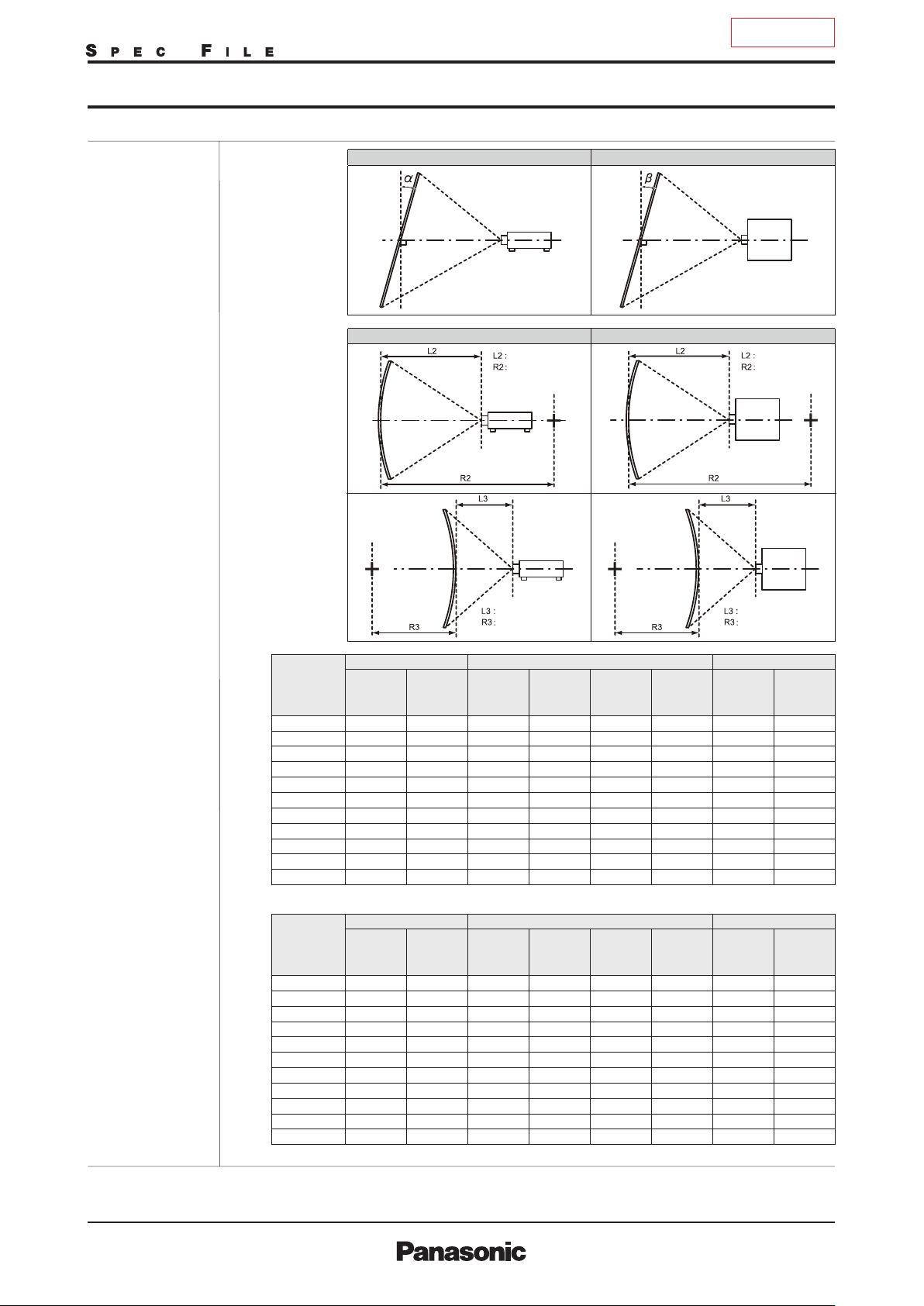
Geometry correction
range
PT-
RCQ10B/RCQ10LB/RCQ10W/RCQ10LW
[VERTICAL KEYSTONE] (viewed from the side) [HORIZONTAL KEYSTONE] (viewed from above)
Screen
Screen
Projection distance
Arc radius
Screen
Vertical arc correction (viewed from the side) Horizontal arc correction (viewed from above)
Projection distance
Arc radius
Screen
Arc center
Screen
Projection distance
Arc radius
[KEYSTONE] and [CURVED] used together Only [CURVED] used
Vertical
keystone
correction
angle α (°)
±20
±20
±20
±20
±8
―
±8
±8
Horizontal
keystone
correction
angle β (°)
±8
―
±8
±8
±15
±15
±15
±15
Projection lens
Model No.
ET-DLE020
ET-DLE035*
ET-DLE055
ET-DLE060
ET-DLE085
ET-DLE105
ET-DLE150
ET-DLE170
ET-DLE250
ET-DLE350
ET-DLE450
Only [KEYSTONE] used
Vertical
keystone
correction
angle α (°)
±5 0 ― ― ― ― ― ―
6
+5/-0 0 ― ― ― ― ― ―
±22
±16
±22
±22
±40
Horizontal
keystone
correction
angle β (°)
±15
±10
±15
±15
±15
±40 ±15 ±20 ±15
±40
±40
±40
±15
±15
±15
When using the optional Upgrade Kit (Model No.: ET-UK20)
Projection lens
Model No.
ET-DLE020
ET-DLE035*
ET-DLE055
ET-DLE060
ET-DLE085
ET-DLE105
ET-DLE150
ET-DLE170
ET-DLE250
ET-DLE350
ET-DLE450
Horizontal
keystone
correction
angle β (°)
0
±15
±10
±15
±15
±40
7
Only [KEYSTONE] used*
Vertical
keystone
correction
angle α (°)
±5
7
+5/-0 0 ― ― ― ― ― ―
±22
±16
±22
±22
±40
±40 ±40 ±20 ±15
±40
±45
±45
±40
±40
±40
[KEYSTONE] and [CURVED] used together Only [CURVED] used
Vertical
keystone
correction
angle α (°)
±20
±20
±20
±20
―
±8
―
±8
±8
Horizontal
keystone
correction
angle β (°)
―
±8
―
±8
±8
±15
±15
±15
±15
Arc center
Min. value
of R2/L2
1.7
―
1.7
1.7
1.1
0.9
0.7
0.4
0.3
Min. value
of R2/L2
―
1.3
―
1.3
1.3
0.9
0.7
0.5
0.3
0.2
Screen
Min. value
of R3/L3
4.3
―
4.3
4.3
2.6
1.7
1.3
0.8
0.6
Min. value
of R3/L3
―
3.3
―
3.3
3.3
2
1.3
1
0.6
0.4
Projection distance
Arc radius
Min. value
of R2/L2
1
―
1
1
0.6
0.5
0.4
0.3
0.2
Min. value
of R2/L2
―
0.8
―
0.8
0.8
0.5
0.4
0.3
0.2
0.2
Min. value
of R3/L3
2.6
―
2.6
2.6
1.5
1
0.7
0.5
0.3
Min. value
of R3/L3
―
1.9
―
1.9
1.9
1.1
0.7
0.6
0.4
0.3
As of August 2019 2/29
PT-RCQ10B/RCQ10LB/RCQ10W/RCQ10LWG_STE_T01_22/08/2019
TENTATIVE
DLP™ Projector
Optical axis shift
Installation
Terminals
Dimensions
(W × H × D)*
Weight
Operation noise
Laser Classication Laser Class
Operating temperature
Operating humidity
8
PT-
DVI-D IN DVI-D 24-pin × 1, DVI 1.0 compliant, compatible with HDCP,
HDMI IN IN
SDI IN BNC × 1,
MULTI PROJECTOR
SYNC IN
MULTI PROJECTOR
SYNC OUT
SERIAL IN
SERIAL OUT
REMOTE 1 IN
REMOTE 1 OUT M3 jack × 1 for link control (for wired remote control)
REMOTE 2 IN
DIGITAL LINK/LAN
LAN RJ-45 × 1 for network connection, PJLink (class 2) compatible,
SLOT SLOT 1 (vacant) for interface boards, SLOT NX compatible
USB USB Type A × 1, for USB memory stick/Wireless Module (Option:AJ-WM50GT),
PT-RCQ10B/PT-RCQ10W
PT-RCQ10LB/PT-RCQ10LW
PT-RCQ10B/PT-RCQ10W
PT-RCQ10LB/PT-RCQ10LW
Risk Group
RCQ10B/RCQ10LB/RCQ10W/RCQ10LW
Vertical: +50%, -16%(powered)
(When using the ET-DLE060, +40%, -16%)
Horizontal: +30%, -10%(powered)
(When using the ET-DLE060, +19%, -10%)
(When using the ET-DLE085/ET-DLE105, +28%, -10%)
(When using the ET-DLE020, +10%, -20%)
NOTE: Optical axis shift function canno t b e operated when used with the ET-DLE055.
If using the ET-DLE035, the optical axis i s fixed.
Ceiling/oor, front/rear
for single link only
HDMI 19-pin × 1, Deep
HD-SDI signal: SMPTE ST 292 compliant
3G-SDI signal: SMPTE ST 424, 425-2 compliant
BNC x 1 TTL Hi-z
BNC x 1 TTL max 10mA
D-sub 9-pin (female) × 1 for external control (RS-232C compliant)
D-sub 9-pin (male) × 1 for link control
M3 jack × 1 for wired remote control
D-sub 9-pin (female) × 1 for external control (parallel)
RJ-45 × 1 for network, DIGITAL LINK connection (HDBaseT™ compliant),
100Base-TX, compatible with Art-Net, PJLink™ (Class 2), eep Color,
HDCP 2.2
10Base-T/100Base-TX, Art-Net compatible
for power supply (DC5V, max 500mA)
3.0 m (9 ft10 in)Power cord length
Molded plasticCabinet materials
498 × 200 × 581 mm (19-19/32 × 7-7/8 × 22-7/8in) with lens
498 × 200 × 538 mm (19-19/32 × 7-7/8 × 21-3/16in) without lens
Approx. 24.2 kg (52.5 lbs.) with lens
Approx. 23.4 kg (51.6 lbs.) without lens
43 dB[NORMAL] /40 dB[QUIET1] / 38dB[QUIET2])
USA and Canada: Class 3R (IEC 60825-1:2007)
Other countries or regions: Class 1 (IEC/EN 60825-1:2014)
ET-DLE020, ET-DLE035, ET-DLE055,
ET-DLE060, ET-DLE085, ET-DLE105,
ET-DLE150,
Standard zoom lens ET-DLE170
ET-DLE250, ET-DLE350, ET-DLE450 Risk Group 3 (IEC 62471-5:2015)
0–45 °C (32–113 °F)*
10%–80% (no condensation)
Color, compatible with HDCP2.2,
Risk Group 2 (IEC 62471-5:2015)
9
As of August 2019 3/29
PT-RCQ10B/RCQ10LB/RCQ10W/RCQ10LWG_STE_T01_22/08/2019
TENTATIVE
DLP™ Projector
PT-
RCQ10B/RCQ10LB/RCQ10W/RCQ10LW
Remote control unit
Power supply
Operation range
Dimensions (W × H × D)
10
Weight*
Other Applications
Supplied accessories
Optional accessories
Digital interface box ET-YFB100G
Digital LINK Switcher ET-YFB200G
Zoom lens ET-DLE020
Zoom lens ET-DLE060
Zoom lens ET-DLE085
Zoom lens ET-DLE105
Zoom lens ET-DLE150
Zoom lens ET-DLE170
(same as supplied lens)
Zoom lens ET-DLE250
Zoom lens ET-DLE350
Zoom lens ET-DLE450
Fixed-focus lens ET-DLE035
Fixed-focus lens ET-DLE055
3 V DC (AAA/R03/LR03 battery × 2)
Approx. 30 m (98 ft5 in) when operated from directly in front of the
signal receptor
48 × 145 × 27 mm (1-7/8 × 5-23/32 × 1-1/16 in)
Approx. 102 g (3.6 ozs.) including batteries
Multi Monitoring and Control Software (for Windows)
Logo Transfer Software (for Windows)
Geometry Manager Pro (for Windows)
Smart Projector Control (iOS/Android)
Power cord with secure lock (× 1) (× 2 for Europe / ASIA models)
Wireless/wired remote control unit (× 1)
Batteries for remote control (AAA/R03 or AAA/LR03 battery × 2)
CD-ROM (Operating Instructions) (× 1)
Lens Mount Cover (× 1)
Lens cover (× 1) (Only models with lens)
Interface Board for DisplayPort ET-MDNDP10
DVI-D input signal board ET-MDNDV10
HDMI input signal board ET-MDNHM10
12G-SDI signal board ET-MDN12G10
Ceiling mount bracket ET-PKD120H (for high ceilings)
ET-PKD120S (for low ceilings)
High-ceiling mount bracket ET-PKD130H
(6-axis adjustment mechanism)
Attachment for ceiling mount bracket ET-PKD130B
Geometry Manager Pro Upgrade kit ET-UK20
Auto Screen Adjustment Upgrade kit ET-CUK10/CUK10P
Early Warning Software ET-SWA100*
11
Wireless Module AJ-WM50
*1 Value is for the supplied standard zoom lens. The value varies depending on the lens.
*2 Measurement, measuring conditions, and method of notation all comply with ISO/IEC 21118:2012 international standards.
*3 Average light-output value of all shipped products measured at center of screen in NORMAL Mode.
*4 Around this time, light output will have decreased by approximately 50 %. IEC62087: 2008 Broadcast contents, NORMAL Mode, Dynamic Contrast [3],
under conditions with 30 °C (86 °F), 700 m (2,297 ft) above sea level, and 0.15 mg/m
depending on environment.
*5 This is supported when the Interface Board for 12G-SDI input (Model No.: ET-MDN12G10) is installed in the slot.
*6 When [VERTICAL KEYSTONE] and [HORIZONTAL KEYSTONE] are used simultaneously, correction cannot be
made exceeding total of 55°.
• When [GEOMETRY] is used, the focus of the entire screen may be lost as correction increases.
• Make the curved screen a circular arc shape with one part of a perfect circle removed.
• Adjustment range of the [GEOMETRY] items may not match the listed projection range depending on the
projection lens. Use this projector within the projection range, otherwise the correction may not work.
*7 Only compatible with dot clock frequency of 27 MHz (pixel repetition signal).
*8 with legs at shortest position.
*9 Limits the luminance when used in locations from 0m to 2,700m (0ft to 8,858ft) above sea level at ambient temperatures of 30°C (86°F) or higher,
or from 2,700m to 4,200m (8,858ft to 13,780ft) above sea level at ambient temperatures of 25°C (77°F) or higher.
*10 Average value. Weight varies for each product.
*11 The symbol at the end of the part number will vary depending on the type of license.
3
of particulate matter. Estimated time until light output declines to 50 % varies
As of August 2019 4/29
PT-RCQ10B/RCQ10LB/RCQ10W/RCQ10LWG_STE_T01_22/08/2019
TENTATIVE
DLP™ Projector
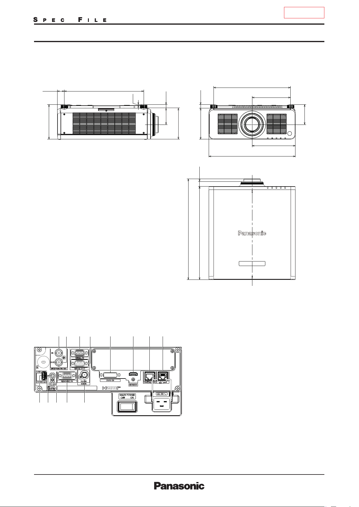
Dimensions
40.5
[1-19/32]
200
[7-7/8]
PT-
457
[18]
RCQ10B/RCQ10LB/RCQ10W/RCQ10LW
442
5
[3/16]
20
95.5
[25/32]
[3-3/4]
180
[7-3/32]
20.5
179.5
28
[17-13/32]
[13/16]
[7-1/16]
498
[19-19/32]
[1 3/32]
221
[8-11/16]
249
[9-13/16]
115.5
[4-9/16]
Terminals
unit : mm (inch)
NOTE : T his ill ustration i s not drawn to scale.
1211109
13
580.84
[22-7/8]
538
[21-3/16]
1
87654321
MULTI PROJECTOR SYNC INPUT
2
MULTI PROJECTOR SYNC OUTPUT
3
SERIAL INPUT
4
SERIAL OUTPUT
5
DVI-D INPUT
6
HDMI INPUT
7
DIGITAL LINK
8
LAN
9
USB
10
REMOTE 1 INPUT
11
REMOTE 1 OUTPUT
12
REMOTE 2 INPUT
13
SDI INPUT
As of August 2019 5/29
PT-RCQ10B/RCQ10LB/RCQ10W/RCQ10LWG_STE_T01_22/08/2019
TENTATIVE
DLP™ Projector
PT-
RCQ10B/RCQ10LB/RCQ10W/RCQ10LW
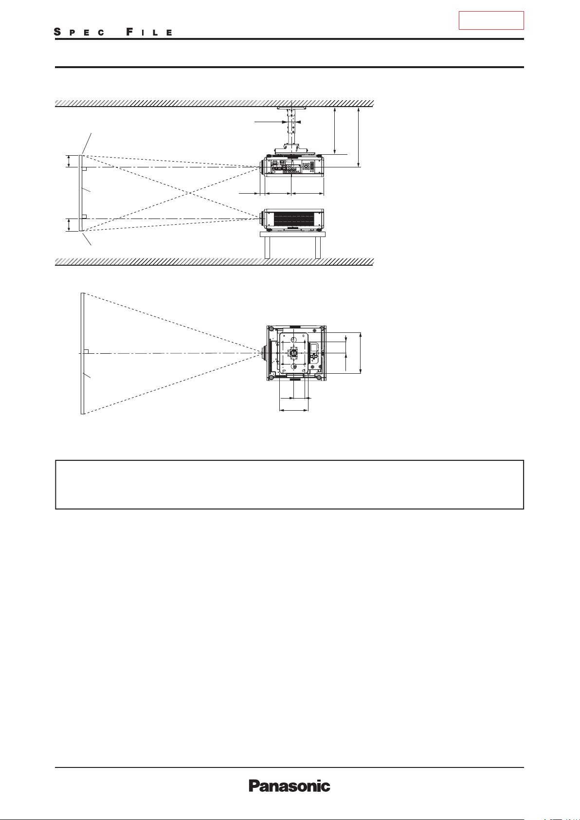
Standard setting-up position (If using other than the ET-DLE035)
ø60. 5
Upper edge of pr ojected image
L
E E
Lower edge of projected i mage
1
*
294244
(11- 9/16)(9 -19/32)
*1 When the lens protrudes to the maximum.
2
*
352–432
(1 3-27/ 32–1 7)
269 mm (10-19/32 in) with the ET-DLE020
2
104 mm (4-3/32 in) with the ET-DLE060
84 mm (3-5/16 in) with the ET-DLE085
88 mm (3-15/32 in) with the ET-DLE105
44 mm (1-23/32 in) with the ET-DLE150
43 mm (1-11/16 in)
with the ET-DLE170
463.5–543. 5*
45 mm (1-25/32 in) with the ET-DLE250
(18- 1/4–21-13/ 32)
51mm (2 in) with the ET-DLE350
95 mm (3-3/4 in) with the ET-DLE450
27 mm (1-1/16 in) with the ET-DLE055
*2 Adjustable in 40 mm (1-9/16 in) steps.
unit : mm (inch)
370
100
Projected image
100
(3-15/1 6)
259
(10- 3/16)
(14- 9/16)
(3 -15/16)
NOT E:
Illustrations show the pro jector
installe d using optional ceiling mo unt
bracket ET-PKD120H , optional bracket
assembly ET-PKD130B and an op tional lens.
Thi s illustrati on is not drawn to scal e.
Cauti on:
•
All construction work should be don e by a qualied technician.
•
When mounting to the ceiling, use the special m ountin g bracket. Furthermore , in order to prevent it from falling
down from the ceiling, use the supplied w ir e on the moun ting bracket.
As of August 2019 6/29
PT-RCQ10B/RCQ10LB/RCQ10W/RCQ10LWG_STE_T01_22/08/2019

TENTATIVE
DLP™ Projector
PT-
RCQ10B/RCQ10LB/RCQ10W/RCQ10LW
Projection distance for 16:10 aspect ratio screen (If using other than the ET-DLE035)
Distance to screen (L )
Screen
size
(diagonal)
[m] [in]
1.27 / 50
1.52 / 60
1.78 / 70
2.03 / 80
2.29 / 90
2.54 / 100
3.05 / 120
3.81 / 150
5.08 / 200
6.35 / 250
7.62 / 300
8.89 / 350
10.16 / 400
12.70 / 500
15.24 / 600
ET-DLE020
Zoom lens
0.280-0.299:1
min. max.
-
-
-
-
-
-
-
-
-
-
0.59
0.64
0.72
0.77
0.90
0.97
1.21
1.30
1.52
1.63
1.83
1.96
2.14
2.29
2.45
2.63
-
-
-
-
ET-DLE060
Zoom lens
ET-DLE085
Zoom lens
ET-DLE105
Zoom lens
0.600-0.801:1 0.782-0.977:1 0.978-1.32:1 1.30-1.89:1 1.71-2.41:1 2.27-3.62:1 3.58-5.45:1 5.36-8.58:1
0.84
0.63
0.76
0.90
1.03
1.17
1.31
1.58
1.99
2.67
3.35
4.03
4.71
5.39
6.75
8.11
1.02
1.20
1.38
1.56
1.74
2.10
2.63
3.53
4.42
5.32
6.21
7.11
8.90
10.69
0.82
1.00
1.17
1.35
1.52
1.70
2.05
2.57
3.44
4.31
5.18
6.06
6.93
8.67
10.42
1.04
1.25
1.47
1.68
1.90
2.11
2.55
3.19
4.27
5.35
6.43
7.51
8.59
10.75
12.91
1.03
1.25
1.47
1.68
1.90
2.12
2.55
3.20
4.29
5.37
6.46
7.54
8.63
10.80
12.97
Zoom
ET-DLE150
Zoom lens
Standard
ET-DLE170
Zoom lens
Throw ratio
2.01
2.43
2.84
3.25
3.66
4.08
4.90
6.14
8.20
10.26
12.33
14.39
16.45
20.58
24.70
min. max.
1.82
2.20
2.58
2.95
3.33
3.71
4.47
5.60
7.50
9.39
11.28
13.18
15.07
18.86
22.64
min. max.min. max.mi n. max.min. max. min. max.min. max.min. max.
1.38
1.41
1.66
1.70
1.95
1.99
2.23
2.28
2.52
2.57
2.81
2.86
3.38
3.44
4.24
4.32
5.67
5.77
7.10
7.23
8.53
8.68
9.96
10.14
11.39
11.59
14.25
14.50
17.11
17.41
2.57
3.10
3.63
4.16
4.69
5.21
6.27
7.86
10.50
13.14
15.79
18.43
21.07
26.36
31.65
ET-DLE250
Zoom lens
2.42
2.92
3.42
3.92
4.42
4.92
5.91
11.75
7.41
15.70
9.91
19.64
12.41
23.59
14.91
27.53
17.40
31.48
19.90
39.37
24.90
47.25
29.89
3.87
4.65
5.44
6.23
7.02
7.81
9.39
ET-DLE350
Zoom lens
3.80
4.59
5.38
6.16
10.57
6.95
11.76
7.74
14.14
9.31
17.71
11.68
23.66
15.61
29.61
19.55
35.56
23.49
41.51
27.42
47.46
31.36
59.36
39.23
71.25
47.11
5.81
7.00
8.19
9.38
ET-DLE450
Zoom lens
5.66
6.85
11.01
8.04
12.89
9.23
14.78
10.43
16.66
11.62
18.55
14.00
22.31
17.58
27.97
23.54
37.39
29.50
46.81
35.46
56.24
41.42
65.66
47.38
75.08
59.30
93.93
112.77
71.22
9.12
Fixed-focus
ET-DLE055
Fixed-
focus lens
0.786:1
0.83
1.00
1.18
1.35
1.53
1.70
2.05
2.58
3.45
-
-
-
-
-
-
Unit: meters
Height from the edge of
screen to center of lens
(E)
ET-DLE085
105/150/250
350/450
0−0.44
0
0
0
0
0
0
0
0
0
0
0
0
0
0
ET-
DLE060
0.07−0.44
−
0.53
0.08
−
0.53
−
0.62
−
0.62
0.09
−
0.71
0.11
−
0.71
−
0.80
0.12
−
0.80
−
0.89
−
0.89
0.13
−
1.07
0.16
−
1.07
−
1.33
−
1.33
0.20
−
1.78
0.27
−
1.78
−
2.22
−
2.22
0.34
−
2.67
0.40
−
2.67
−
3.11
−
3.11
0.47
−
3.55
0.54
−
3.55
−
4.44
0.67
−
4.44
−
5.33
−
5.33
0.81
ET-
DLE055
0.34
0.40
0.47
0.54
0.61
0.67
0.81
1.01
1.35
-
-
-
-
-
-
Screen
size
(diagonal)
[m] [in]
1.27 / 50
1.52 / 60
1.78 / 70
2.03 / 80
2.29 / 90
2.54 / 100
3.05 / 120
3.81 / 150
5.08 / 200
6.35 / 250
7.62 / 300
8.89 / 350
10.16 / 400
12.70 / 500
15.24 / 600
ET-DLE020
Zoom lens
0.280 - 0.299:1
min. max.
-
-
-
-
-
-
-
-
-
-
1.94
2.10
2.36
2.53
2.95
3.18
3.97
4.27
4.99
5.35
6.00
6.43
7.02
7.51
8.04
8.63
-
-
-
-
ET-DLE060
Zoom lens
0.600-0.801:1
2.8
2.1
3.4
2.5
3.9
2.9
4.5
3.4
5.1
3.8
5.7
4.3
6.9
5.2
8.6
6.5
11.6
8.7
14.5
11.0
17.4
13.2
20.4
15.4
23.3
17.7
29.2
22.1
35.1
26.6
Distance to screen (L )
Zoom
ET-DLE085
Zoom lens
ET-DLE105
Zoom lens
ET-DLE150
Zoom lens
Standard
ET-DLE170
Zoom lens
ET-DLE250
Zoom lens
ET-DLE350
Zoom lens
ET-DLE450
Zoom lens
Throw ratio
0.782-0.977:1 0.978-1.32:1 1.30-1.89:1 1.71-2.41:1 2.27-3.62:1 3.58-5.45:1 5.36-8.58:1
2.7
3.3
3.9
4.4
5.0
5.6
6.7
8.4
11.3
14.1
17.0
19.9
22.7
28.5
34.2
3.4
4.1
4.8
5.5
6.2
6.9
8.4
10.5
14.0
17.6
21.1
24.6
28.2
35.3
42.3
3.4
4.1
4.8
5.5
6.2
7.0
8.4
10.5
14.1
17.6
21.2
24.8
28.3
35.4
42.5
min. max.min. max.mi n. max.min. max. min. max.min. max.min. max.
4.5
4.6
5.5
5.6
6.4
6.5
7.3
7.5
8.3
8.4
9.2
9.4
11.1
11.3
13.9
14.2
18.6
18.9
23.3
23.7
28.0
28.5
32.7
33.3
37.4
38.0
46.7
47.6
56.1
57.1
6.6
8.0
9.3
10.7
12.0
13.4
16.1
20.1
26.9
33.7
40.4
47.2
54.0
67.5
81.1
min. max.
6.0
10.2
7.2
11.9
8.5
13.6
9.7
15.4
10.9
17.1
12.2
20.6
14.7
25.8
18.4
34.5
24.6
43.1
30.8
51.8
37.0
60.5
43.2
69.1
49.4
86.5
61.9
103.8
74.3
8.4
29.9
18.6
19.1
12.5
12.7
7.9
36.1
22.5
23.0
15.1
15.3
9.6
42.3
26.4
26.9
17.6
17.9
11.2
48.5
30.3
30.8
20.2
20.4
12.8
54.7
34.2
34.7
22.8
23.0
14.5
60.8
38.1
38.6
25.4
25.6
16.1
73.2
45.9
46.4
30.6
30.8
19.4
91.8
57.7
58.1
38.3
38.6
24.3
122.7
77.2
77.6
51.2
51.5
32.5
153.6
96.8
97.1
64.1
64.4
40.7
184.5
116.3
116.7
77.1
77.4
48.9
215.4
135.9
136.2
90.0
90.3
57.1
246.3
155.4
155.7
102.9
103.3
65.3
308.2
194.6
194.7
128.7
129.2
81.7
370.0
233.7
233.8
154.6
155.0
98.1
Fixed-focus
ET-DLE055
Fixed-
focus lens
0.786:1
2.7
3.3
3.9
4.4
5.0
5.6
6.7
8.5
11.3
-
-
-
-
-
-
Unit: feet
Height from the edge of
screen to center of lens
(E)
ET-DLE085
105/150/250
350/450
ET-
DLE060
−
1.5
0
0.2−1.5
0
−
1.7
−
1.7
0.3
0
−
2.0
0.3
−
2.0
0
−
2.3
0.4
−
2.3
0
−
2.6
0.4
−
2.6
−
2.9
0
0.4
−
2.9
0
−
3.5
−
3.5
0.5
0
−
4.4
0.7
−
4.4
0
−
5.8
0.9
−
5.8
0
−
7.3
1.1
−
7.3
−
8.7
0
1.3
−
8.7
0
−
10.2
1.5
−
10.2
0
−
11.7
−
11.7
1.8
0
−
14.6
2.2
−
14.6
0
−
17.5
2.6
−
17.5
ET-
DLE055
1.1
1.3
1.5
1.8
2.0
2.2
2.6
3.3
4.4
-
-
-
-
-
-
• T he value for L (distance to screen) varies slightly within ±5% dep ending on the zoom lens characteristics.
• T he zoom lens characteristics may cause slight image distortion.
• W hen using keystone correction is used, the image is corrected in the d irectio n that red uces its projected size.
• T he brightness varies depending on the zoom setting.
Note: When the ET-DLE0 55 is mounted, the opti cal lens shift function cannot be used.
As of August 2019 7/29
PT-RCQ10B/RCQ10LB/RCQ10W/RCQ10LWG_STE_T01_22/08/2019
TENTATIVE
DLP™ Projector
PT-
RCQ10B/RCQ10LB/RCQ10W/RCQ10LW
Projection distance for 16:9 aspect ratio screen (If using other than the ET-DLE035)
Distance to screen (L )
Screen
size
(diagonal)
[m] [in]
1.27 / 50
1.52 / 60
1.78 / 70
2.03 / 80
2.29 / 90
2.54 / 100
3.05 / 120
3.81 / 150
5.08 / 200
6.35 / 250
7.62 / 300
8.89 / 350
10.16 / 400
12.70 / 500
15.24 / 600
ET-DLE020
Zoom lens
0.280-0.299:1
min. max.
-
-
-
-
-
-
-
-
-
-
0.65
0.61
0.79
0.74
0.99
0.93
1.34
1.25
1.68
1.56
2.02
1.88
2.36
2.20
2.70
2.52
-
-
-
-
ET-DLE060
Zoom lens
ET-DLE085
Zoom lens
ET-DLE105
Zoom lens
0.600-0.802:1 0.783-0.977:1 0.979-1.32:1 1.30-1.89:1 1.72-2.41:1 2.27-3.62:1 3.58-5.45:1 5.36-8.58:1
0.87
0.64
0.78
0.92
1.06
1.20
1.34
1.62
2.04
2.74
3.44
4.14
4.84
5.54
6.93
8.33
1.05
1.24
1.42
1.60
1.79
2.16
2.71
3.63
4.55
5.47
6.39
7.31
9.15
10.99
0.85
1.03
1.21
1.39
1.57
1.75
2.10
2.64
3.54
4.43
5.33
6.23
7.12
8.91
10.71
1.07
1.29
1.51
1.73
1.95
2.17
2.62
3.28
4.39
5.50
6.61
7.72
8.83
11.05
13.27
1.06
1.29
1.51
1.73
1.96
2.18
2.63
3.29
4.41
5.52
6.64
7.76
8.87
11.10
13.33
Zoom
ET-DLE150
Zoom lens
Standard
ET-DLE170
Zoom lens
Throw ratio
2.07
2.49
2.92
3.34
3.77
4.19
5.04
6.31
8.43
10.55
12.67
14.79
16.91
21.15
25.39
min. max.
1.87
2.26
2.65
3.04
3.43
3.82
4.60
5.76
7.71
9.65
11.60
13.55
15.49
19.38
23.27
min. max.min. max.mi n. max.min. max. min. max.min. max.min. max.
1.45
1.42
1.75
1.71
2.05
2.00
2.35
2.30
2.64
2.59
2.94
2.89
3.54
3.47
4.44
4.36
5.93
5.82
7.43
7.29
8.93
8.76
10.42
10.23
11.92
11.70
14.91
14.64
17.90
17.58
2.64
3.19
3.73
4.27
4.82
5.36
6.45
8.08
10.80
13.51
16.23
18.95
21.66
27.10
32.53
ET-DLE250
Zoom lens
2.49
3.00
3.51
4.03
4.54
5.05
6.08
12.08
7.62
16.14
10.19
20.19
12.75
24.25
15.32
28.30
17.89
32.35
20.46
40.46
25.59
48.57
30.72
3.97
4.79
5.60
6.41
7.22
8.03
9.65
ET-DLE350
Zoom lens
3.91
4.72
5.53
6.34
7.15
10.87
7.96
12.09
9.58
14.54
12.00
18.21
16.05
24.32
20.10
30.44
24.14
36.55
42.67
28.19
48.78
32.24
61.01
40.33
73.24
48.42
5.98
7.20
8.43
9.65
ET-DLE450
Zoom lens
5.82
7.05
8.27
9.50
10.72
11.95
14.40
18.08
24.20
30.33
36.45
42.58
48.71
60.96
73.21
9.39
11.32
13.26
15.20
17.13
19.07
22.94
28.75
38.44
48.12
57.81
67.49
77.18
96.55
115.91
Fixed-focus
ET-DLE055
Fixed-
focus lens
0.786:1
0.85
1.03
1.21
1.39
1.57
1.75
2.11
2.65
3.55
-
-
-
-
-
-
Unit: meters
Height from the edge of
screen to center of lens
(E)
ET-DLE085
105/150/250
350/450
-
0.06−0.46
-
0.07−0.55
-
0.09−0.64
-
0.10−0.73
-
0.11−0.82
-
0.12−0.91
-
0.15−1.10
-
0.19−1.37
-
0.25−1.83
-
0.31−2.28
-
0.37−2.74
-
0.44−3.20
-
0.50−3.65
-
0.62−4.57
-
0.75−5.48
ET-
DLE060
0
−
0.46
0
−
0.55
0
−
0.64
−
0.73
0
0
−
0.82
−
0.91
0
0
−
1.10
−
1.37
0
0
−
1.83
−
2.28
0
0
−
2.74
−
3.20
0
0
−
3.65
0
−
4.57
−
5.48
0
ET-
DLE055
0.31
0.37
0.44
0.50
0.56
0.62
0.75
0.93
1.25
-
-
-
-
-
-
Screen
size
(diagonal)
[m] [in]
1.27 / 50
1.52 / 60
1.78 / 70
2.03 / 80
2.29 / 90
2.54 / 100
3.05 / 120
3.81 / 150
5.08 / 200
6.35 / 250
7.62 / 300
8.89 / 350
10.16 / 400
12.70 / 500
15.24 / 600
ET-DLE020
Zoom lens
0.280 - 0.299:1
min. max.
-
-
-
-
-
-
-
-
-
-
2.13
2.00
2.59
2.43
3.25
3.05
4.40
4.10
5.51
5.12
6.63
6.17
7.74
7.22
8.86
8.27
-
-
-
-
Distance to screen (L )
Zoom
ET-DLE060
Zoom lens
ET-DLE085
Zoom lens
ET-DLE105
Zoom lens
ET-DLE150
Zoom lens
Standard
ET-DLE170
Zoom lens
ET-DLE250
Zoom lens
ET-DLE350
Zoom lens
ET-DLE450
Zoom lens
Throw ratio
0.600-0.802:1 0.783-0.977:1 0.979-1.32:1 1.30-1.89:1 1.72-2.41:1 2.27-3.62:1 3.58-5.45:1 5.36-8.58:1
2.1
2.6
3.0
3.5
3.9
4.4
5.3
6.7
9.0
11.3
13.6
15.9
18.2
22.7
27.3
2.8
3.5
4.1
4.7
5.3
5.9
7.1
8.9
11.9
14.9
17.9
21.0
24.0
30.0
36.0
2.8
3.4
4.0
4.5
5.1
5.7
6.9
8.7
11.6
14.5
17.5
20.4
23.4
29.2
35.1
3.5
4.2
5.0
5.7
6.4
7.1
8.6
10.8
14.4
18.1
21.7
25.3
29.0
36.2
43.5
3.5
4.2
5.0
5.7
6.4
7.2
8.6
10.8
14.5
18.1
21.8
25.5
29.1
36.4
43.7
min. max.min. max.mi n. max.min. max. min. max.min. max.min. max.
4.6
4.8
5.6
5.7
6.6
6.7
7.5
7.7
8.5
8.7
9.5
9.6
11.4
11.6
14.3
14.6
19.1
19.5
23.9
24.4
28.8
29.3
33.6
34.2
38.4
39.1
48.0
48.9
57.7
58.7
6.8
8.2
9.6
11.0
12.4
13.7
16.5
20.7
27.7
34.6
41.6
48.5
55.5
69.4
83.3
min. max.
6.1
10.5
7.4
12.2
8.7
14.0
10.0
15.8
11.2
17.6
12.5
21.2
15.1
26.5
18.9
35.4
25.3
44.3
31.7
53.2
38.1
62.2
44.4
71.1
50.8
88.9
63.6
106.7
76.4
8.7
8.2
9.8
11.5
13.2
14.9
16.6
19.9
25.0
33.4
41.8
50.3
58.7
67.1
84.0
100.8
13.0
15.7
18.4
21.0
23.7
26.3
31.7
39.6
52.9
66.2
79.5
92.8
106.1
132.8
159.4
12.8
15.5
18.1
20.8
23.5
26.1
31.4
39.4
52.7
65.9
79.2
92.5
105.8
132.3
158.9
19.6
23.6
27.6
31.7
35.7
39.7
47.7
59.7
79.8
99.9
119.9
140.0
160.0
200.2
240.3
19.1
23.1
27.1
31.2
35.2
39.2
47.2
59.3
79.4
99.5
119.6
139.7
159.8
200.0
240.2
30.8
37.1
43.5
49.9
56.2
62.6
75.3
94.3
126.1
157.9
189.7
221.4
253.2
316.8
380.3
Fixed-focus
ET-DLE055
Fixed-
focus lens
0.786:1
2.8
3.4
4.0
4.6
5.2
5.7
6.9
8.7
11.7
-
-
-
-
-
-
Unit: feet
Height from the edge of
screen to center of lens
(E)
ET-DLE085
105/150/250
350/450
-0.2
-0.2
-0.3
-0.3
-0.4
-0.4
-0.5
-0.6
-0.8
-1.0
-1.2
-1.4
-1.6
-2.0
-2.5
−
−
−
−
−
−
−
−
−
−
−
−
−
−
−
10.5
12.0
15.0
18.0
1.5
1.8
2.1
2.4
2.7
3.0
3.6
4.5
6.0
7.5
9.0
ET-
DLE060
0−1.5
0
−
1.8
−
2.1
0
−
2.4
0
0
−
2.7
−
3.0
0
−
3.6
0
0
−
4.5
−
6.0
0
−
7.5
0
0
−
9.0
−
10.5
0
−
12.0
0
0
−
15.0
−
18.0
0
ET-
DLE055
1.0
1.2
1.4
1.6
1.8
2.0
2.5
3.1
4.1
-
-
-
-
-
-
• T he value for L (distance to screen) varies slightly within ±5% depending on the zoom lens characteristics.
• T he zoom lens characteristics may cause slig ht image distortio n.
• When using keystone correctio n is used, the imag e is c or rected in the directio n that red uces its pro jected size.
• T he brightness varies de pending on the zo om setting.
Note: When the ET-D LE055 is m ounted, the optical lens shift function cannot be used.
As of August 2019 8/29
PT-RCQ10B/RCQ10LB/RCQ10W/RCQ10LWG_STE_T01_22/08/2019
TENTATIVE
DLP™ Projector
PT-
RCQ10B/RCQ10LB/RCQ10W/RCQ10LW
Projection distance for 4:3 aspect ratio screen (If using other than the ET-DLE035)
Distance to screen (L )
Screen
size
(diagonal)
[m] [in]
1.27 / 50
1.52 / 60
1.78 / 70
2.03 / 80
2.29 / 90
2.54 / 100
3.05 / 120
3.81 / 150
5.08 / 200
6.35 / 250
7.62 / 300
8.89 / 350
10.16 / 400
12.70 / 500
15.24 / 600
ET-DLE020
Zoom lens
0.337-0.360:1
min. max.
-
-
-
-
-
-
-
-
-
-
0.72
0.67
0.87
0.81
1.10
1.03
1.47
1.38
1.85
1.73
2.23
2.08
2.60
2.43
2.98
2.78
-
-
-
-
ET-DLE060
Zoom lens
ET-DLE085
Zoom lens
ET-DLE105
Zoom lens
0.724-0.965:1 0.943-1.18:1 1.18-1.59:1 1.56-2.27:1 2.06-2.90:1 2.73-4.35:1 4.30-6.55:1 6.46-10.3:1
0.96
0.71
0.87
1.02
1.18
1.33
1.48
1.79
2.25
3.02
3.79
4.56
5.33
6.10
7.64
9.18
1.16
1.37
1.57
1.77
1.97
2.38
2.99
4.00
5.01
6.03
7.04
8.05
10.08
12.11
0.94
1.14
1.33
1.53
1.73
1.93
2.32
2.91
3.90
4.89
5.88
6.86
7.85
9.82
11.80
1.18
1.42
1.67
1.91
2.16
2.40
2.89
3.62
4.84
6.07
7.29
8.51
9.73
12.17
14.62
1.18
1.42
1.67
1.91
2.16
2.41
2.90
3.63
4.86
6.09
7.32
8.55
9.78
12.23
14.69
Zoom
ET-DLE150
Zoom lens
Standard
ET-DLE170
Zoom lens
Throw ratio
2.29
2.75
3.22
3.69
4.15
4.62
5.55
6.96
9.29
11.63
13.96
16.30
18.63
23.30
27.97
min. max.
2.07
2.50
2.93
3.35
3.78
4.21
5.07
6.35
8.50
10.64
12.78
14.93
17.07
21.36
25.64
min. max.min. max.mi n. max.min. max. min. max.min. max.min. max.
1.60
1.56
1.93
1.89
2.26
2.21
2.59
2.54
2.92
2.86
3.25
3.18
3.91
3.83
4.89
4.80
6.54
6.42
8.19
8.04
9.84
9.66
11.48
11.28
13.13
12.90
16.42
16.13
19.72
19.37
2.92
3.52
4.12
4.72
5.31
5.91
7.11
8.91
11.90
14.89
17.88
20.88
23.87
29.85
35.84
ET-DLE250
Zoom lens
4.39
2.75
5.28
3.31
6.17
3.88
7.07
4.44
7.96
5.01
8.85
5.57
10.64
6.71
13.32
8.40
17.78
11.23
14.06
22.25
16.88
26.71
19.71
31.18
22.54
35.64
28.19
44.58
33.85
53.51
ET-DLE350
Zoom lens
4.32
5.21
6.10
10.64
7.00
11.99
7.89
13.34
8.78
16.03
10.56
20.07
13.24
26.80
17.69
33.54
22.15
40.27
26.61
47.01
31.06
53.74
35.52
67.21
44.43
80.68
53.35
6.60
7.95
9.29
ET-DLE450
Zoom lens
6.45
7.80
9.14
10.49
11.84
13.19
15.89
19.94
26.69
33.44
40.18
46.93
53.68
67.17
80.67
10.37
12.50
14.63
16.77
18.90
21.03
25.30
31.70
42.37
53.04
63.70
74.37
85.04
106.37
127.70
Fixed-focus
ET-DLE055
Fixed-
focus lens
0.946:1
0.94
1.14
1.34
1.54
1.74
1.93
2.33
2.93
3.92
-
-
-
-
-
-
Unit: meters
Height from the edge of
screen to center of lens
(E)
ET-DLE085
105/150/250
350/450
0
0
0
0
0
0
0
0
0
0
0
0
0
0
0
−
−
−
−
−
−
−
−
−
−
−
−
−
−
−
0.50
0.60
0.70
0.80
0.91
1.01
1.21
1.51
2.01
2.51
3.02
3.52
4.02
5.03
6.04
ET-
DLE060
0.08−0.50
0.09
−
0.60
−
0.70
0.11
0.12
−
0.80
0.14
−
0.91
−
1.01
0.15
0.18
−
1.21
−
1.51
0.23
0.30
−
2.01
−
2.51
0.38
0.46
−
3.02
−
3.52
0.53
0.61
−
4.02
0.76
−
5.03
−
6.04
0.91
ET-
DLE055
0.38
0.46
0.53
0.61
0.69
0.76
0.91
1.14
1.52
-
-
-
-
-
-
Screen
size
(diagonal)
[m] [in]
1.27 / 50
1.52 / 60
1.78 / 70
2.03 / 80
2.29 / 90
2.54 / 100
3.05 / 120
3.81 / 150
5.08 / 200
6.35 / 250
7.62 / 300
8.89 / 350
10.16 / 400
12.70 / 500
15.24 / 600
ET-DLE020
Zoom lens
0.337-0.360:1
min. max.
-
-
-
-
-
-
-
-
-
-
2.36
2.20
2.85
2.66
3.61
3.38
4.82
4.53
6.07
5.68
7.32
6.82
8.53
7.97
9.78
9.12
-
-
-
-
Distance to screen (L )
Zoom
ET-DLE060
Zoom lens
ET-DLE085
Zoom lens
ET-DLE105
Zoom lens
ET-DLE150
Zoom lens
Standard
ET-DLE170
Zoom lens
ET-DLE250
Zoom lens
ET-DLE350
Zoom lens
ET-DLE450
Zoom lens
Throw ratio
0.724-0.965:1 0.943-1.18:1 1.18-1.59:1 1.56-2.27:1 2.06-2.90:1 2.73-4.35:1 4.30-6.55:1 6.46-10.3:1
2.3
2.9
3.4
3.9
4.4
4.9
5.9
7.4
9.9
12.4
15.0
17.5
20.0
25.1
30.1
3.2
3.8
4.5
5.1
5.8
6.5
7.8
9.8
13.1
16.5
19.8
23.1
26.4
33.1
39.7
3.1
3.7
4.4
5.0
5.7
6.3
7.6
9.6
12.8
16.0
19.3
22.5
25.8
32.2
38.7
3.9
4.7
5.5
6.3
7.1
7.9
9.5
11.9
15.9
19.9
23.9
27.9
31.9
39.9
48.0
3.9
4.7
5.5
6.3
7.1
7.9
9.5
11.9
16.0
20.0
24.0
28.0
32.1
40.1
48.2
min. max.min. max.mi n. max.min. max. min. max.min. max.min. max.
5.1
5.2
6.2
6.3
7.3
7.4
8.3
8.5
9.4
9.6
10.4
10.7
12.6
12.8
15.8
16.1
21.1
21.5
26.4
26.9
31.7
32.3
37.0
37.7
42.3
43.1
52.9
53.9
63.6
64.7
7.5
9.0
10.6
12.1
13.6
15.2
18.2
22.8
30.5
38.1
45.8
53.5
61.1
76.5
91.8
min. max.
6.8
8.2
9.6
11.0
12.4
13.8
16.6
20.8
27.9
34.9
41.9
49.0
56.0
70.1
117.6
84.1
9.6
11.5
13.5
15.5
17.4
19.4
23.3
29.2
39.0
48.9
58.7
68.5
78.3
97.9
9.0
10.9
12.7
14.6
16.4
18.3
22.0
27.6
36.8
46.1
55.4
64.7
73.9
92.5
111.1
14.4
17.3
20.3
23.2
26.1
29.0
34.9
43.7
58.3
73.0
87.6
102.3
116.9
146.2
175.5
14.2
17.1
20.0
23.0
25.9
28.8
34.7
43.4
58.0
72.7
87.3
101.9
116.5
145.8
175.0
21.7
26.1
30.5
34.9
39.3
43.8
52.6
65.8
87.9
110.0
132.1
154.2
176.3
220.5
264.7
21.1
25.6
30.0
34.4
38.9
43.3
52.1
65.4
87.6
109.7
131.8
154.0
176.1
220.4
264.7
34.0
41.0
48.0
55.0
62.0
69.0
83.0
104.0
139.0
174.0
209.0
244.0
279.0
349.0
419.0
Fixed-focus
ET-DLE055
Fixed-
focus lens
0.946:1
3.1
3.7
4.4
5.0
5.7
6.3
7.6
9.6
12.8
-
-
-
-
-
-
Unit: meters
Height from the edge of
screen to center of lens
(E)
ET-DLE085
105/150/250
350/450
0
0
0
0
0
0
0
0
0
0
0
0
0
0
0
ET-
DLE060
0.3
−
1.7
2.0
2.3
2.6
3.0
3.3
4.0
5.0
6.6
8.3
9.9
11.6
13.2
16.5
19.8
1.7
0.3
−
2.0
−
2.3
0.4
0.4
−
2.6
0.5
−
3.0
−
3.3
0.5
0.6
−
4.0
−
5.0
0.8
1.0
−
6.6
−
8.3
1.3
1.5
−
9.9
−
11.6
1.8
2.0
−
13.2
2.5
−
16.5
−
19.8
3.0
−
−
−
−
−
−
−
−
−
−
−
−
−
−
−
ET-
DLE055
1.3
1.5
1.8
2.0
2.3
2.5
3.0
3.8
5.0
-
-
-
-
-
-
• The value for L (distance to screen) varies slightly within ±5% dependi ng on the zo om lens characteristics.
• The zoom lens characteristics may cause slig ht image distortion.
• When using keystone correction is used , the image is corrected in the dir ection that red uces its projected size.
• The brightness varies depend ing on the zoom setting.
Note: When the ET-DLE0 55 is mounted, the opti cal lens shift function cannot be used.
As of August 2019 9/29
PT-RCQ10B/RCQ10LB/RCQ10W/RCQ10LWG_STE_T01_22/08/2019
 Loading...