

Panasonic pt-lb0ntu, pt-lb0u, pt-lb50su Operating Instructions Manual
Panason·c
LCD Projector I Commercial Use I
Operating Instructions
Model No. PT-LB50NTU
PT-LB50U
PT-LB50SU
Before operating this product, please read the instructions carefully and save this
manual for future use.
TQBJ 0192

Dear Panasonic Customer:
This instruction booklet provides all the necessary operating informationthat
you might require. We hope it will help youto get the most out of your new
product, and that you will be pleased with your Panasonic LCD projector.
The serial numberof yourproduct may be foundon its bottom. Youshould note
it in the spaceprovidedbelow and retainthis booklet incase serviceis required.
Model number: PT-LB50NTU I PT-LB50U I PT-LB50SU
Serial number:
IMPORTANT SAFETY NOTICE
WARNING: TO REDUCETHE RISK OF FIREOR ELECTRIC SHOCK, DO
NOT EXPOSETHIS PRODUCTTO RAIN OR MOISTURE.
Power
Supply:ThisLCDProjectoris
designedtoope
rate
on100V-
240
V,50Hz/60
HzAC,house
currentoni
y.
CAUTION:TheACpo
wer
cord
whichis
supplied
with
the
projectorasana
ccessory
can
onlybeused
forpower
supp
liesupto125V,7A.Ifyou
needtousehigh
er
vo
ltagesorcurrents
than
this,youwillneedtoobtaina
separate
250
V
power
cord
.If
you
usethe
accessorycordinsuchsitua
tio
ns,
fire
may
resul
t.
The lightning flash with arrowhead symbol, withinan
equilateral triangle, is intended to alert the user to the
presence of uninsulated "dangerous voltage" within the
product's enclosure that may be of sufficient magnitude to
constitute a risk of electric shock to persons.
I_WARNING II
it
The exclamation point within an equilateral triangle is
intended to alert the user to the presence of important
operating and maintenance (servicing) instructions in the
literature accompanying the product.
CAUTION:
Thisequipmen
tis
equipped
witha
three-pingrounding-typepower
plug
.Do
not
removethe
groundingpinon
thepowerplug.Thi
s
plug
will
onl
yfita
groun
ding
-typepoweroutlet.Thisisa
safety
feature.If
youare
unabletoin
sert
the
plug
intotheoutlet,contact
an
electrician.
Donot
defeatthe
purposeofthe
grounding
plug.
(
{
~
~l
j
!
l
)
I
Do not remove
2
-EN
GLISH
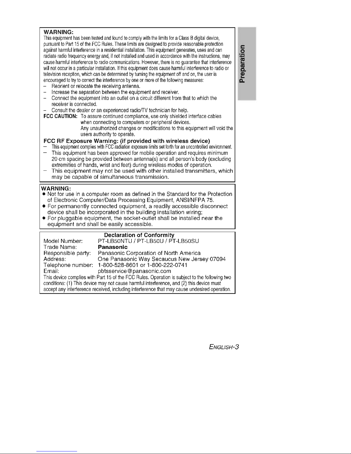
WARNING:
Thisequi
pment
has
beentestedandfoundtoc
ompl
ywiththelim
its
fora
Class
Bdi
gifaldevice
,
pu
rsua
nftoP
art15of
theFCCRules.Theselimits
aredesigned
toprov
idereasonablepr
ote
cti
on
aga
instharmful
inte
rterenceinaresidentialinstalla
tion.
Thi
sequi
pment
gene
rates,usesand
can
r
adi
ate
radiofreq
uencyenergyand,ifnotinsta
lled
andused
ina
cco
rda
ncewith
theins
tru
ctio
ns,
may
c
auseharmful
interterencetor
adioco
mmunica
tions.However,thereisno
guarantee
thatin
terte
rence
willnotoccurin
apa
rticu
larinsta
llation.Ifthisequipment
doescauseh
anmfulinterte
renceto
radi
oor
televisionreception,whic
hcanbede
term
inedbyturn
ing
theequ
ipment
off
andon,
theuseris
encouraged
totryto
correctthe
interterence
byoneorm
oreofthefollowing
measure
s:
-
Reorientorrel
ocate
the
recei
ving
antenna.
-
Increase
the
separationbetween
the
equipment
and
recei
ver.
- C
onnect
the
equipment
intoanoutlet ona
circuit
differentfrom
that
towhich
the
recei
ver
isc
onne
cted.
- Consult
the
dealeroranexperienced
radiofTV
technician
for
help.
FCC
CAUTION:Toas
sure
continued
compliance,use
onlyshielded
intertace
cables
when
connecting
toc
omputer
sor
peripheraldevice
s.
Anyun
authorized
change
sor
modificationstothis
equipment
willvoid
the
u
sersauthori
tyto
operate.
FCC RF Exposure Warning: (if provided
with
wireless device)
- T
hisequ
ipmentcomplies
with
FCC
radiationexposurelim
itssetforthforanun
controlledenvironment.
-
This
equipment
has
been
approvedfor
mobile
operation
and
requires
minimum
20cmspacingbepro
vided
between
antenna
(s)
and
all
person's
body
(excluding
e
xtremitiesofhands
,wrist
and
feet)
during
wireless
modesofoperation
.
- This equipment may not be used with other installed transmitters, which
may be capable of simultaneous transmission.
WARNING:
• Notfor use in a computer
room
asdefinedin the Standard for the Protection
of Electronic Computer/Data Processing Equipment, ANSI/NFPA75.
• For permanently connected equipment, a readily accessible disconnect
device shall be incorporated in the building installation wiring;
• For pluggable equipment, the socket-outlet shall be installed near the
equipment and shall be easily accessible.
Declaration of
Conformity
Model Number: PT-LB50NTU / PT-LB50U / PT-LB50SU
Trade Name:
Panasonic
Responsible party: Panasonic Corporation of North America
Address: One Panasonic Way Secaucus New Jersey 07094
Telephone number: 1-800-528-8601 or 1-800-222-0741
Email: pbtsservice@panasonic.com
Thisdevice co
mplieswithP
art15of
the
FCC
Rules.
Operation
issubjectto
the
follo
wing
two
conditions:
(1)
Thisdevicemay
notcause
harmful
interterence,and(2)
thisdevicemust
acceptany
interterencerecei
ved,includinginterterencethatmaycauseunde
sired
operation.
ENGLlSH-3
c
o
:;:::
E
III
C.
e
Do
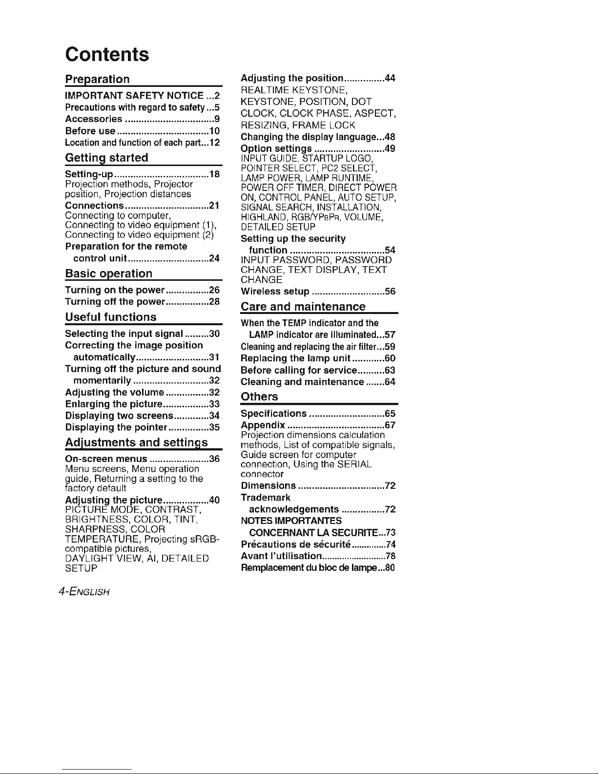
Contents
Preparation
IMPORTANT SAFETY NOTICE 2
Precautions with regard to safety 5
Accessories
9
Before use 10
Locationandfunctionof
each
part 12
Getting started
Setting-up
18
Projection methods. Projector
position. Projection distances
Connections
21
Connecting to computer.
Connecting to video equipment (1),
Connecting to video equipment (2)
Preparation
for
the
remote
control
unit
24
Basic operation
Turningonthe
power
26
Turning
off
the
power
28
Useful
functions
Selecting the
input
signal
30
Correcting
the image
position
automatically
31
Turning
off
the
picture
and
sound
momentarily
32
Adjusting
the
volume
32
Enlarging
the
picture
33
Displaying
two
screens
34
Displaying
the
pointer
35
Adjustments
and
settings
On-screen
menus
36
Menu screens, Menu operation
guide, Returning a setting to the
factory default
Adjusting
the
picture
40
PICTURE MODE. CONTRAST ,
BRIGHTNESS. COLOR. TINT.
SHARPNESS, COLOR
TEMPERATURE. Projecting sRGBcompatible pictures,
DAYLIGHT VIEW. AI, DETAILED
SETUP
4-ENGLISH
Adjusting
the
position
44
REALTIME KEYSTONE,
KEYSTONE. POSITION, DOT
CLOCK, CLOCK PHASE, ASPECT.
RESIZING. FRAME LOCK
Changing the display language 48
Option
settings
.49
INPUT
GUIDE.STARTUP
LOGO
,
POINTER
SELECT
,PC2
SELECT
,
LAMP
POWER,LAMP
RUNTIME
.
POWER
OFF
TIMER.DIRECT
POWER
ON,
CONTROL
PANEL,AUTO
SETUP
,
SIGNAL
SEARCH,INSTALLATION
,
HIGHLAND.RGB
IYPsPR.VOLUME
,
DETAILED
SETUP
Sellingupthe
security
function
54
INPUT PASSWORD, PASSWORD
CHANGE. TEXT DISPLAY, TEXT
CHANGE
Wireless
setup
56
Care and maintenance
Whenthe
TEMP
indicator and the
LAMPindicator areiIIuminated 57
Cleaning
and
replacing
theair filter 59
Replacing the
lamp
unil..
60
Before
calling
for
service
63
Cleaning and
maintenance
64
Others
Specifications
65
Appendix
67
Projection dimensions calculation
methods. List of compatible signals,
Guide screen for computer
connection, Using the SERIAL
connector
Dimensions
72
Trademark
acknowledgements
72
NOTESIMPORTANTES
CONCERNANT
LA SECURITE 73
Precautionsdesecurlte
74
Avant
l'utltlsatlon
78
Remplacementdu bloc
de lampe 80

Precautions with regard to safety
WARNING
If
you
notice
smoke, strange
smellsornoise
coming
from
the
projector,
disconnect
the
power
cord
plug
from
the
wall outlet.
• Do not continue to use the projector in such cases, otherwise fire or
electric shocks could result.
• Check that no more smoke is coming out, and then contact an Authorized
Service Center for repairs.
• Do not attempt to repair the projector yourself, as this can be dangerous.
Do
not
install
this
projector
in a place
whichisnot
strong
enough
to
take
the
full
weightofthe
projector.
• If the installation location is not strong enough, it may fall down or tip over,
and severe injury or damage could result.
Installation
work
(suchasceiling
suspension)
should
only
be carried
out
by a qualified technician.
• If installation is not carried out correctly, there is the danger that injury or
electric shocks may occur.
If
foreign
objectsorwater
get
inside
the
projector, or if
the
projector
is
droppedorthe
cabinet
is broken,
disconnect
the
power
cord
plug
from
the
wall
outlet.
• Continued use of the projector in this condition may result in fire or electric
shocks.
• Contact an Authorized Service Center for repairs.
Do
not
overload the
wall
outlet.
• If the power supply is overloaded (for example, by using too many
adapters), overheating may occur and fire may result.
Do
not
remove the
coverormodify
it in any way.
• High voltages can cause fire or electric shocks.
• For any inspection, adjustment and repair work, please contact an
Authorized Service Center.
Clean
the
power
cord
plug
regularly
to prevent it
from
becoming
covered in
dust.
• If dust builds up on the power cord plug, the resulting humidity can
damage the insulation, which could result in fire. Pull the power cord plug
out from the wall outlet and wipe it with a dry cloth.
• If not using the projector for an extended period of time, pull the power
cord plug out from the wall outlet.
Do
notdoanything
that
might
damage the
power
cordorthe
power
cord
plug.
• Do not damage the power cord, make any modifications to it, place it near
any hot objects, bend it excessively, twist it, pull it, place heavy objects on
top of it or wrap it into a bundle.
ENGLlSH-5
c
o
:;:::
E
III
C.
e
Do

• If fhe power cord is used while damaged, electric shocks, short-circuits or
fire may result.
• Ask an Authorized Service Center to carry out any repairs to the power
cord that might be necessary.
Do
not
handle the
power
cord
plug
with
wet hands.
• Failure to observe this may result in electric shocks.
Insert
the
power
cord
plug
securely
into
the
wall
outlet.
• If the plug is not inserted correctly, electric shocks or overheating could
result.
• Do not use plugs which are damaged or wall outlet which are coming
loose from the wall.
Do
not
place
the
projectorontopofsurfaces
which
are unstable.
• If the projector is placed on top of a surface which is sloped or unstable, it
may fall down or tip over, and injury or damage could result.
Do
not
place
the
projector
into
water
or let it become wet.
• Failure to observe this may result in fire or electric shocks.
Do
not
place
the
projectoronsoft
materials
such
as carpetsorsponge
mats.
• Doing so may cause the projector to overheat, which can cause burns, fire
or damage to the projector.
Do
not
place
liquid
containersontopofthe
projector.
• If water spills onto the projector or gets inside it, fire or electric shocks
could result.
• If any water gets inside the projector, contact an Authorized Service
Center.
Do
not
insert
any
foreign
objects
into
the
projector.
• Do not insert any metal objects or flammable objects into the projector or
drop them onto the projector, as doing so can result in fire or electric
shocks.
Keep
the
batteries
out
of the reach of infants.
• If the batteries are swallowed, death by suffocation may result. If you
believe that the batteries may have been swallowed, seek medical advice
immediately.
Do
not
allow
the
+ and -
terminalsofthe batteriestocome
into
contact
with
metallic
objects
such
as necklacesorhairpins.
• Failure to observe this may cause the batteries to leak, overheat, explode
or catch fire.
• Store the batteries in a plastic bag and keep them away from metallic
objects.
During a
thunderstorm,donot
touch
the
projectororthe
cable.
• Electric shocks can result.
Do
not
use
the
projector
in a bath or shower.
• Fire or electric shocks can result.
6-ENGLISH
Do
not
look
into
the lens
while
the
projector
is being used.
• Strong light is emitted from the projector's lens.
If you look directly into this
light, it can hurt and damage your eyes.
• Be especially careful not to let young children look into the lens. In
addition, disconnect the power cord plug when you are away from the
projector.
Do
not
place
your
skin
into
the
light
beam
while
the
projector
is being
used.
• Strong light is emitted from the projector's lens. If you place directly into
this light, it can hurt or damage your skin.
Do
not
place
your
handsorother
objects
closetothe
air
outlet
port.
• Heated air comes out of the air outlet port. Do not place your hands or
face, or objects which cannot withstand heat close to this port [allow at
least10cm (4") of space], otherwise burns or damage could result.
Replacement
of
the
lamp
should
only
be carried
out
by a qualified
technician
.
• The lamp has high internal pressure.
If improperly handled, explosion
might result.
• The lamp can easily become damaged if struck against hard objects or
dropped, and injury or malfunctions may result.
When
replacing
the
lamp,
allow
it to
cool
for
at least one
hour
before
handlingi!.
• The lamp cover gets very hot, and touching it can cause burns.
Before replacing
the
lamp, be
suretodisconnect
the
power
cord
plug
from
the
wall outle!.
• Electric shocks or explosions can result if this is not done.
Caution
Do
not
cover
the
air
inlet
portorthe
air
outlet
port.
• Doing so may cause the projector to overheat, which can cause fire or
damage to the projector.
• Do not place the projector in narrow, badly ventilated places such as
closets or bookshelves.
• Do not place the projector on cloth or papers, as these materials could be
drawn into the air inlet port.
Do
not
set
up the
projectorinhumidordusty
placesorin places where
the
projector
may
come
into
contact
with
smokeorsteam.
• Using the projector under such conditions may result in fire or electric
shocks.
When
disconnecting
the
power
cord,
hold
the
plug,
not
the cord.
• If the power cord itself is pulled, the cord will become damaged, and fire,
short-circuits or serious electric shocks may result.
c
o
:;:::
E
III
C.
e
Do
ENGLlSH-7

Always
disconnect
all cables before
moving
the
projector.
• Moving the projector with cables still attached can damage the cables,
which could cause tire or electric shocks to occur.
Do
not
place
any
heavy
objectsontopofthe
projector.
• Failure to observe this may cause the projector to become unbalanced
and fall, which could result in damage or injury.
Do
not
short-circuit,
heatordisassemble
the
batteries or place
them
into
waterorfire.
• Failure to observe this may cause the batteries to overheat, leak, explode
or catch fire, and burns or other injury may result.
When
inserting
the batteries, make sure
the
polarities
(+ and -) are
correct.
• Ifthe batteries are
inserted
incorrectly, they mayexplode or leak,andfire, injury
orcontamination of the batterycompartment andsurrounding areamay
result.
Use
only
the
specified
batteries.
• If incorrect batteries are used, they may explode or leak, and fire, injury or
contamination of the battery compartment and surrounding area may result.
Do
not
mix
old
and
new
batteries.
• If the batteries are inserted incorrectly, they may explode or leak, and fire,
injury or contamination of the battery compartment and surrounding area
may result.
Do
not
put
your
weightonthis
projector.
• You could fall or the projector could break, and injury may result.
• Be especially careful not to let young children stand or sit on the projector.
If
not
using
the
projector
for
an extended
periodoftime,
disconnect
the
power
cord
plug
from
the wall outlet.
• If dust builds up on the power cord plug, the resulting humidity may
damage the insulation, which could result in fire.
• This projector continues to draw approximately 4 W of power even when
the power is turned off.
Disconnect
the
power
cord
plug
from
the
wall
outlet
as a
safety
precaution
before
carrying
out
any
cleaning.
• Electric shocks can result if this is not done.
If the
lamp
has broken, ventilate
the
room
immediately. Do
not
touch
or
bring
your
face
close
to the broken pieces.
• Failure to observe this may cause the user to absorb the gas which was
released when the lamp broke and which contains nearly the same
amount of mercury as fluorescent lamps, and the broken pieces may
cause injury.
• If you believe that you have absorbed the gas or that the gas has got into
your eyes or mouth, seek medical advice immediately.
• Ask your dealer to replace the lamp unit and check the inside of the
projector.
8-ENGLISH
Ask an Authorized Service Center to clean inside the projector at least once a year.
• "
dustislellto
build up inside the
projector
without
being
cleaned
out, it
can result in fire or
problems
with operation.
• It isa goodideato
clean
theinsideof theprojector
before
the
season
forhumid
weather
arrives.
Askyour
nearest
Authorized
Service
Centerto cleanthe
projector
when
required.
Please
discuss
withthe
Authorized
Service
Center
regarding
cleaning
costs.
We are constantly making efforts to preserve and maintain a clean environment.
Please take non repairable units back to
your
dealer or a recycling company.
c
o
:;:::
E
III
C.
e
Do
NOTICE:
•
This
product has a
High
Intensity
Discharge
(HID)
lamp
that
contains
a
small
amount
of mercury. It also contains lead in
some
components.
Disposal of
these
materials
may
be regulated in
your
community
due
to
environmental
considerations.
For
disposal or recycling information
please
contact
your
local authorities. or the Electronics Industries
Alliance:
shltp'l!www
eiae
mg >
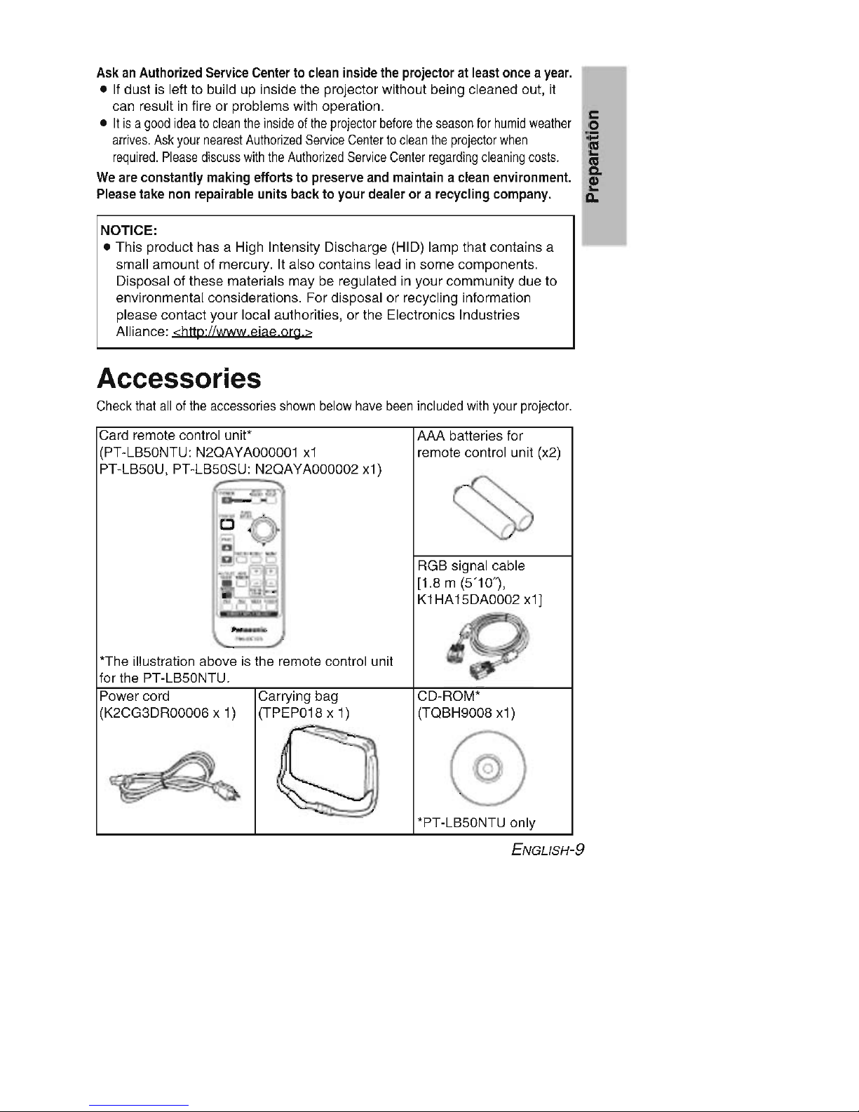
Accessories
Check that all of the accessories shown below have been included with your projector.
-
, .-
CD-ROM'
(TOBH9008
x1)
RGB
signal cable
[1.8 m (5'10
').
K1HA15DA0002
x1]
AAA
batteries for
remote control unit (x2)
Carrying
bag
(TPEP018
x 1)
B
-:
~
_
~A
l
D •
,0..
L.i''"-,
...
'The
illustration
above
is the remote control unit
for the
PT-LB50NTU.
Power
cord
(K2CG3DR00006
x 1)
Card remote control
unit'
(PT-LB50NTU:
N20AYA000001
x1
PT-LB50U.
PT-LB50SU:
N20AYA000002
x1)
'PT-LB50NTU
only
ENGLlSH-9
Before use
Caution when moving the projector
Be
sure
to use the
accessory
carrying
bag when
moving
the
projector.
When placing the projector inside the carrying bag, position it so that the lens
is facing upward. Do not place the projector with its adjustable legs extended
and do not put anything else in the bag other than the projector, cables and
the remote control unit.
Cautions regarding setup
Avoid
setting
up in places
which
are
subjecttovibrationorshocks.
The internal parts can be damaged, which may cause malfunctions or
accidents.
Avoid
setting
up in places
which
are
subjecttosudden
temperature
changes,
such
as near an
air
conditioner.
The life of the lamp may be shortened.
Do
not
set
up the
projector
near high-voltage
power
linesornear
motors.
The projector may be subject to electromagnetic interference.
If
installing
the
projectortothe
ceiling,
ask
a qualified
technician
to
carry
out
all
installation
work.
You will need to purchase the separate installation kit (Model No.ET-PKB50).
Furthermore, all installation work should only be carried out by a qualified
technician.
If
using
this
projectorathigh
elevations (above 1 400 m), set the
"HIGHLAND" to
"ON".
(Refer to page 52.)
Failure to observe this may result in malfunctions.
10-ENGLISH
Notes on use
In
ordertoget
the
best
picture
quality
Draw curtains or blinds over any windows and turn off any lights near the
screen to prevent outside light or light from indoor lamps from shining onto
the screen.
Do
not
touch
the
surfacesofthe
lens
with
your
bare hands.
If the surface of the lens becomes dirty from fingerprints or anything else, this
will be magnified and projected onto the screen.
Screen
Do not apply any volatile substances which may cause discoloration to the
screen, and do not let it become dirty or damaged.
Lamp
The lamp may need to be replaced earlier due to variables such as individual
lamp characteristics, usage conditions and the installation environment,
especially when the projector is subjected to continuous use for more than
10 hours or the power is frequently turned on and off.
Liquid
crystal
panel
The liquid crystal panel of the projector is built with very high precision
technology to provide fine picture details. Occasionally, a few non-active
pixels may appear on the screen as fixed points of blue, green or red.
Please note that this does not affect the performance of your LCD.
ENGLlSH-11
c
o
:;:::
E
III
C.
e
Do
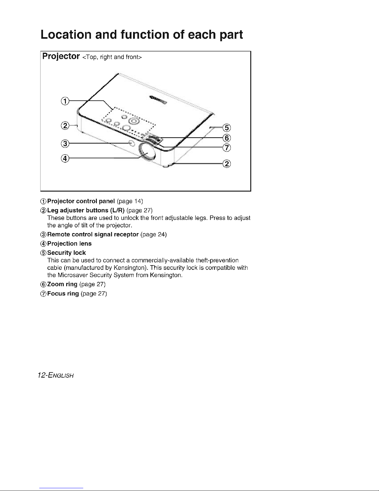
Location and function of each part
Projector <Top, right and fron!>
@~------"
-""--
------\:
4}------~
~
~---
®
G)Projector
control
panel (page 14)
@Leg
adjuster
buttons
(L/R) (page 27)
These buttons are used to unlock the front adjustable legs. Press to adjust
the angle of tilt of the projector.
@Remote
control
signal receptor (page 24)
@Projection lens
® Security
lock
This can be used to connect a commercially-available theft-prevention
cable (manufactured by Kensington). This security lock is compatible with
the Microsaver Security System from Kensington.
@Zoom ring (page 27)
CZJ
Focus ring (page 27)
12-ENGLISH
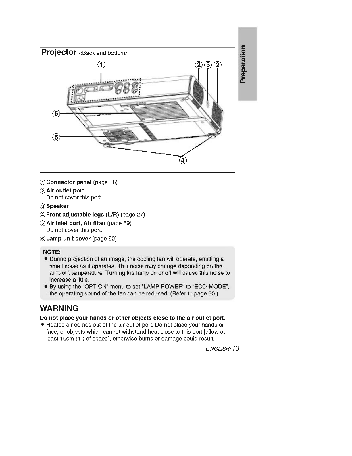
Projector <Back and bottom>
T
----
....
.......
"..
'-0~=-
~~
-=---
-
,
fi}
,:
..
..
-
..
:-------~.
~
~
~
G)Connector panel (page 16)
@Air
outlet
port
Do not cover this port.
@Speaker
@Front
adjustable
legs
(L/R) (page 27)
@Air
inlet
port,
Air
filler
(page 59)
Do not cover this port.
®Lamp
unit
cover
(page 60)
NOTE:
• During projection of an image, the cooling fan will operate, emitting a
small noise as it operates. This noise may change depending on the
ambient temperature. Turning the lamp on or off will cause this noise to
increase a little.
• By using the "OPTION" menu to set "LAMP POWER" to "ECO-MODE",
the operating sound of the fan can be reduced. (Refer to page 50.)
WARNING
Do
not
place
your
handsorother
objects
closetothe
air
outlet
port
.
• Heated air comes out of the air outlet port. Do not place your hands or
face, or objects which cannot withstand heat close to this port [allow at
least 10cm (4") of space], otherwise burns or damage could result.
ENGLlSH-13
c
o
:;:::
E
III
C.
e
Do
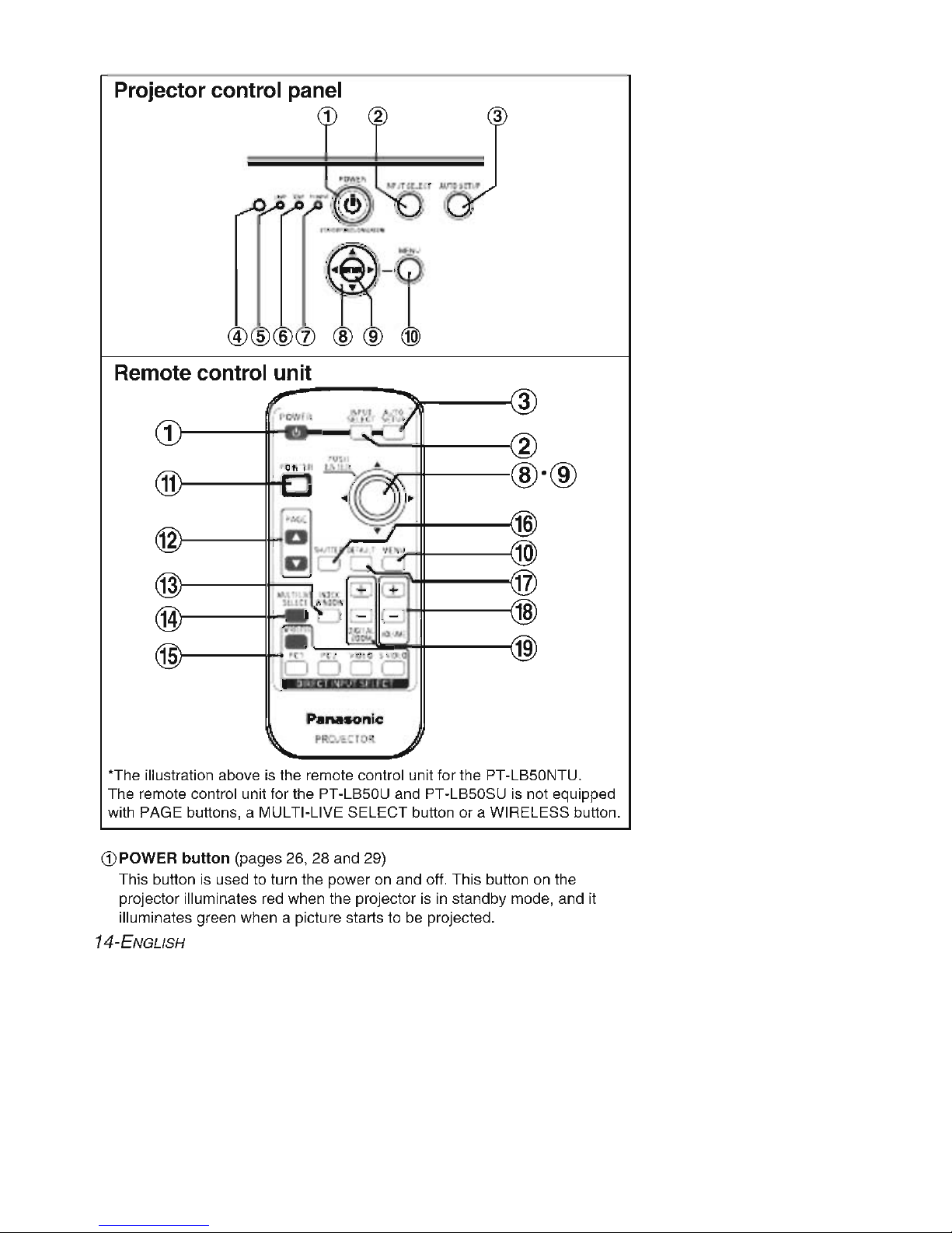
Projector control panel
1
-'
-'
3
1
2
11
8·®
16
12
10
13
~
1
~
~
.
14
18
a . l
oll
"N
t"~
19
1
P
anason
ic
PR:,,,
.: r
o:t
'The illustration above is the remote control unit for the PT-LB50NTU.
The remote control unit for the PT-LB50U and PT-LB50SU is not equipped
with PAGE buttons, a MULTI-LIVE SELECT button or a WIRELESS button.
CD
POWER
button
(pages 26, 28 and 29)
This button is used to turn the power on and off. This button on the
projector illuminates red when the projector is in standby mode, and it
illuminates green when a picture starts to be projected.
14-ENGLISH
@INPUT SELECT
button
(pages 27 and 30)
This button is used to switch the input signals from the connected
equipment.
c
@AUTO SETUP
button
(pages 27 and 31) 0
:;:::
If this button is pressed while a RGB signal is being projected, the position E
of the image and the settings for "DOT CLOCK" and "CLOCK PHASE" will III
C.
be adjusted automatically.
l!!
@lIIumination
sensor
(page 42)
Do
This sensor detects the luminance when the "DAYLIGHT VIEW" function
is operating. Do not cover the projector and do not place any object on the
projector when using it.
®LAMP
indicator
(page 58)
This indicator illuminates when it is time to replace the lamp unit. It flashes
if a circuit abnormality is detected.
@TEMP
indicator
(page 57)
This indicator illuminates if an abnormally high temperature is detected inside
the projectoror around it. If the temperature rises above a certain level, the
power supply will be turned off automatically and the indicatorwill flash.
CZJ
PC INPUT
indicator
This indicator illuminates when a signal is being input to the connector (PC
1 IN or PC 2 IN) selected using the input select buttons.
®
Arrow
(.&"".... and
~)
buttons
(page 38)
These buttons are used to select and adjust items in the on-screen menus.
®ENTER
button
(page 38)
This button is used to accept and to activate items selected in the on-screen
menus.
@!MENU
button
(pages 36 and 38)
This button is used to display the menu screen. When a menu screen is
being displayed, this button can be used to return to a previous screen or
to clear the screen.
®POINTER
button
(page 35)
This button is used to display a pointer on the projected images.
@PAGE
buttons
(PT-LB50NTU only)
These buttons are used when the projector is controlled by means of a
wireless network. Refer to the accessory CD-ROM for details.
@INDEXWINDOWbutton
(page 34)
This button can be used to split the image projection area into a still picture
and a moving picture. You can also select this function from the on-screen
menu (refer to page 53).
@MULTI-
L1
VE SELECT
button
(PT-LB50NTU only)
This button is used when the projector is controlled by means of a wireless
network. Refer to the accessory CD-ROM for details.
(continued on next page)
ENGLlSH-15
(continued from previous page)
@DIRECT INPUT SELECT
buttons
(pages 27 and 30)
You can select the input signal directly by pushing these buttons (the
WIRELESS button is for the PT-LB50NTU only).
@SHUTIER
button
(page 32)
This button is used to momentarily turn off the picture and sound. You can
also select this function from the on-screen menu (refer to page 53).
@DEFAULT bu
tt
on (page 39)
This button is used to reset the projector adjustment values to the factory
default settings.
@VOLUME
+/-
buttons
(page 32)
These buttons are used to adjust the volume of the sound that is output
from the projector's built-in speaker and VARIABLE AUDIO OUT
connector. Refer to page 52 for details on how to adjust the volume
without using the remote control unit.
@iDIGITAL ZOOM
+/-
buttons
(page 33)
These buttons are used to enlarge the projected image.
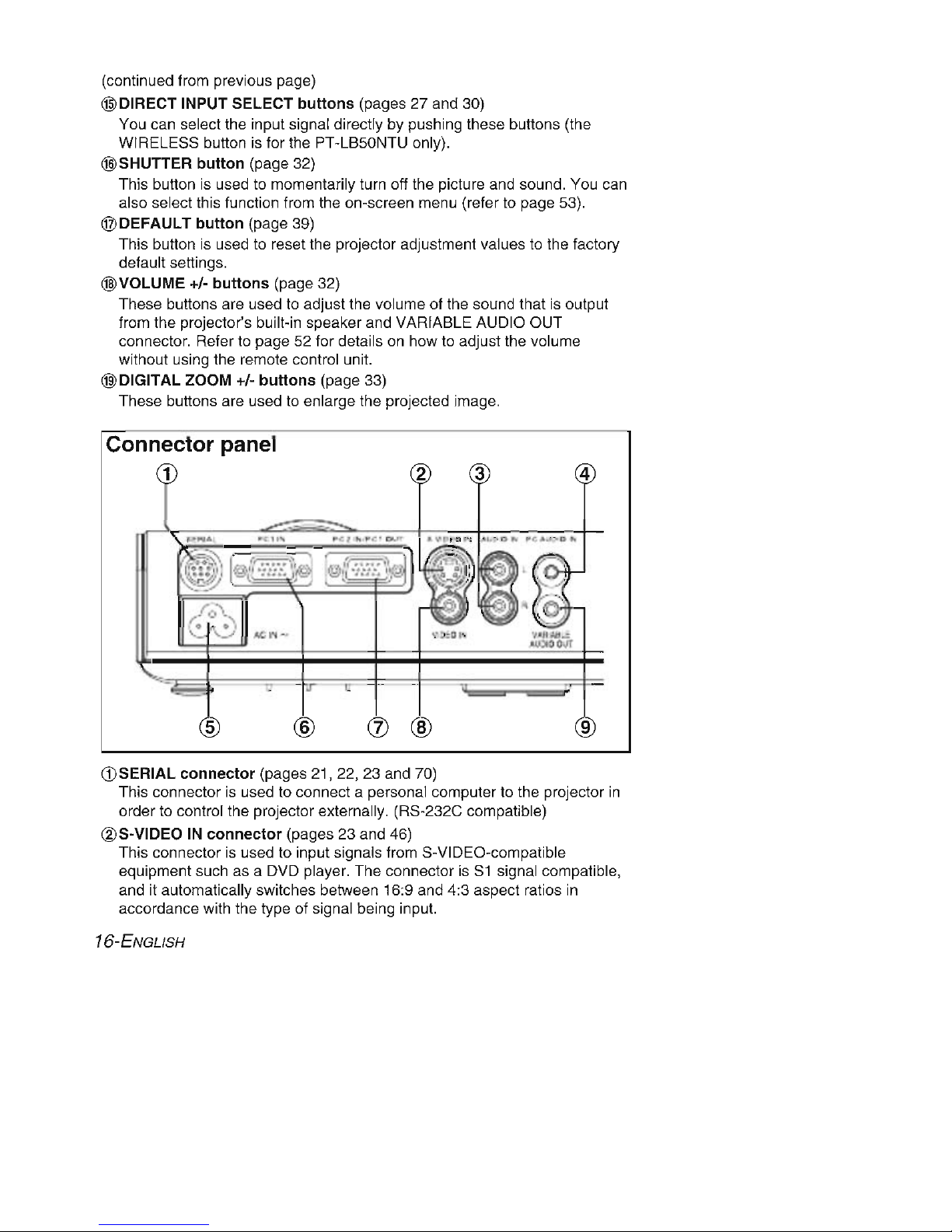
Connector panel
1 4
5
6
(j) 8
9
CD
SERIAL
connector
(pages 21
,22,23
and 70)
This connector is used to connect a personal computer to the projector in
order to control the projector externally. (RS-232C compatible)
@S-VIDEO IN
connector
(pages 23 and 46)
This connector is used to input signals from S-VIDEO-compatible
equipment such as a DVD player. The connector is S1 signal compatible,
and it automatically switches between 16:9 and 4:3 aspect ratios in
accordance with the type of signal being input.
16-ENGLISH
@AUDIO IN L-R
connectors
(for
S-VIDEOIVIDEO) (page 23)
@PC AUDIO IN
connector
(pages 21 and 22)
®Power
input
socket
(AC IN) (page 26)
The accessory power cord is connected here.
Do not use any power cord other than the accessory power cord.
®PC 1 IN
connector
(pages 21 and 22)
This connector is used to input RGB signals and
YPSPR
signals.
(1)PC 2 IN I PC 1 OUT
connector
(pages 21, 22 and 50)
This connector is used to input or output RGB signals and
YPSPR
signals.
Adjust "PC2 SELECT' in the "OPTION" menu to select whether you want
input or output with this connector.
®VIDEO IN
connector
(page 23)
This connector is used to input video signals from video equipment such
as a video deck.
@VARIABLE AUDIO OUT
connector
(pages 21
,22
, and 23)
This connector is used to output the audio signals which are input to the
projector. If audio equipment is connected to this connector, no sound will
be output from the built-in speakers.
c
o
:;:::
E
III
C.
e
Do
ENGLlSH-17
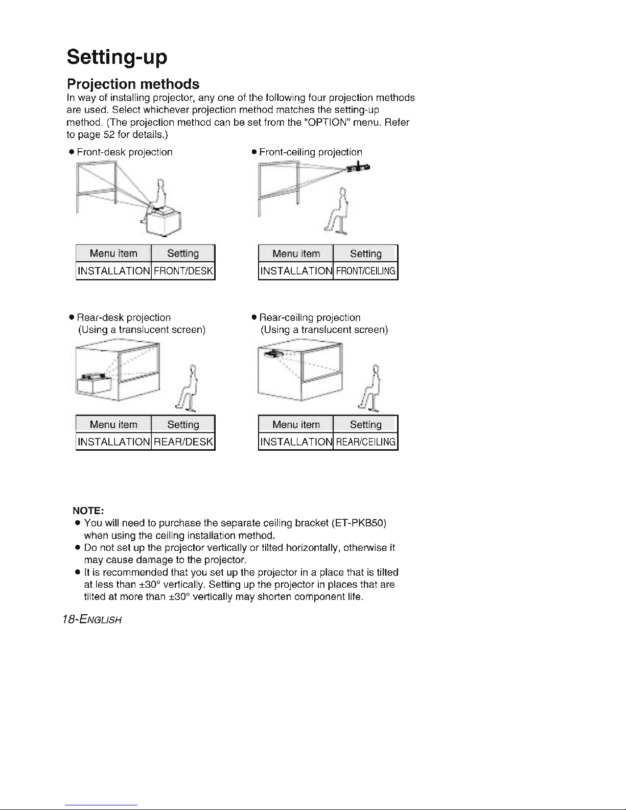
Setting-up
Projection methods
In way of installing projector ,
anyone
of the following four projection methods
are used. Select whichever projection method matches the setting-up
method. (The projection method can be set from the "OPTION" menu. Refer
to page 52 for details.)
• Front-desk projection • Front-ceiling projection
r
~
:~
.,b
~
k-:e
,,
-=:=
r
'"
r
/i1
Menu item Setting
Menu item Setting
INSTALLATION
FRONT
/DESK
INSTALLATION
FRONT
/CEILING
Menu item Setting Menu item Setting
• Rear-ceiling projection
(Using a translucent screen)
-.:-.--
• Rear-desk projection
(Using a translucent screen)
-------=
INSTALLATION REAR/DESK INSTALLATION
REAR/CEILING
NOTE:
• You will need to purchase the separate ceiling bracket (ET-PKB50)
when using the ceiling installation method.
• Do not set up the projector vertically or tilted horizontally, otherwise it
may cause damage to the projector.
• It is recommended that you set up the projector in a place that is tilted
at less than ±30" vertically. Setting up the projector in places that are
tilted at more than ±30" vertically may shorten component life.
18-ENGLISH
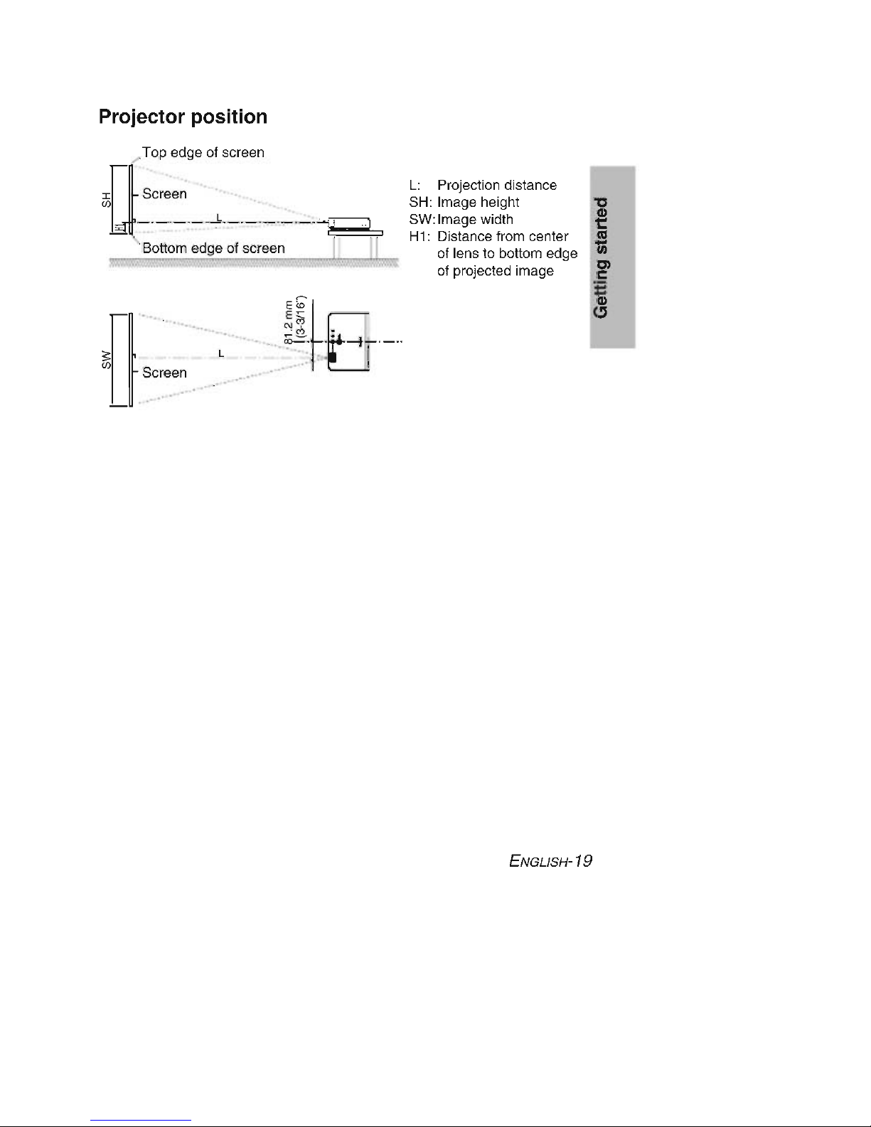
Projector position
L: Projection distance
SH: Image height
"C
Gl
SW:Image width t::
H1: Distance from center
l'Cl
'lii
of lens to bottom edge
Cl
of projected image c
~
G
.....
\,
~
.....
, '..
w,',\"""
·:':
". •,
....•.•.,.........
, •....
\w
..
,~
···
'
..
Top edge of screen
,-
iJ5il
Screen " . '.
-
'-
'- '-'~'::-'77-
'-
'-
---z=?
.. ..
Bottom edge of screen
..'
..'
ENGLlSH-19
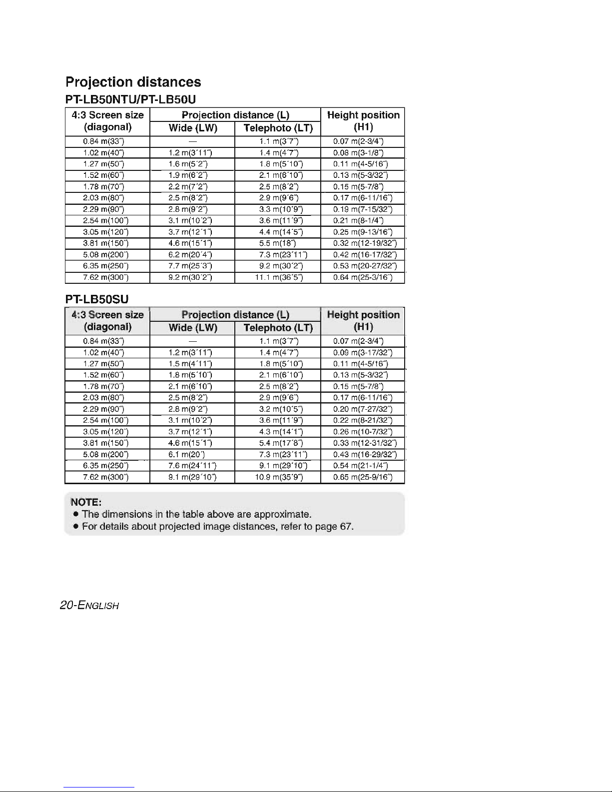
Projection distances
PT-LB50NTUlPT-LB50U
4:3 Screen size Projection distance
ILl
Height
position
(diagonal)
Wide (LW)
Telephoto
(LT)
(H1)
0.S4 m(33·) -
1.1 m(3"T)
0.07 m(2
-314
·)
1.02 m(40}
1.2 m(3·
11}
1.4 m
(47
·)
O
.OS
m(3-1/S}
1.27
m(SO
}
1.6 m(S·2} 1.S m(S·10}
0.11 m(4-S/16}
1.S2 m(60·)
1.9 m(6-2·) 2.1 m(6·10·)
0.13 m(S
-3132-)
1.7S m(70}
2.2 m(7·2}
2.S m(S·2·)
O.lSm(S-7/S}
2.03
m(SO
}
2.S m(S-2} 2.9 m(9-6}
0.
17m(6
-11116}
2.29 m(90}
2.S m(9-2} 3.3 m(10-9}
0.19 m(7-1S/32}
2.S4 m(100}
3.1 m(10-2}
3.6 m(11-9·)
0.21 m(S-1/4·)
3.0S m(120}
3.7 m(12
·1}
4.4 m(14·S}
0.2S m(9-13/16}
3.S1 m(1S0}
4.6 m(
lS
-1}
S.S m(
lS
} 0.32 m(12-19/32")
S
.OS
m(200} 6.2 m(20"4}
7.3 m(23·
11}
0.42 m(16-17/32}
6.3S m(2S0}
7.7 m(2S·3} 9.2 m(30·2}
0.S3 m(20-27/32}
7.62 m(300}
9.2 m(30·
2}
11.1 m(36·S}
0.64 m(2S-3/16}
PT-LB50SU
4:3 Screen size Projection distance
ILl
Height
position
(diagonal)
Wide (LW)
Telephoto
(LT)
(H1)
0.S4 m(33}
-
1.1 m
(37}
0.07 m(2-314}
1.02 m(40}
1.2 m(3·
11}
1.4 m(4"T) 0.09 m(3-17/32}
1.27 mlSOl 1.S mr4"
lll
1.S mIS·10l
0.11 m14-S/16l
1.S2 m(60·) 1.S m(S·10} 2.1 m(6·10}
0.13 m(S
-3132
}
1.7S m(70}
2.1 m(6-10}
2.S m(S-2-)
O.
lS
m(S-7/S}
2.03 m(SO}
2.S m(S·2}
2.9 m(9·6·)
0.
17m(6
-11/16}
2.29 m(90}
2.S m(9·2} 3.2 m(10·S}
0.20 m(7-27/32}
2.S4 m(100}
3.1 m(10-2} 3.6 m(11-9}
0.22 m(S-21/32}
3.0S m(120}
3.7 m(12
·1}
4.3 m(14·1}
0.26 m(10-7/32}
3.S1 m(1S0}
4.6 m(
lS
·1}
S.4 m(17·S}
0.33 m(12-31/32}
S
.OS
m(200} 6.1 m(20")
7.3 m(23·11}
0.43 m(16-29/32 }
6.3S m(2S0}
7.6 m(24-11} 9.1 m(29-10}
0.S4 m(21-1/4}
7.62 m(300}
9.1 m(29
·W)
10.9 m(3S·9}
0.6S m(2S-9/16}
NOTE:
• The dimensions in the table above are approximate.
• For details about projected image distances, reter to page 67.
20 -ENGLISH
1----
RGB signal cable
(accessory)
DIN 8-pin
(male)
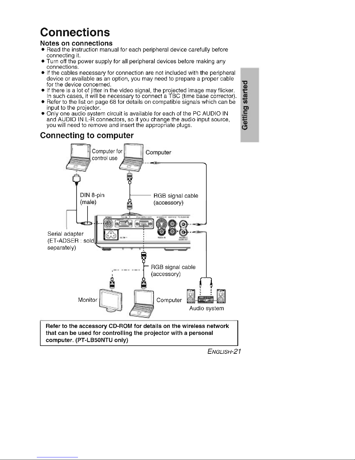
Connections
Notes on connections
• Read the instruction manual for each peripheral device carefully before
connecting it.
• Turn off the power supply for all peripheral devices before making any
connections.
• If the cables necessary for connection are not included with the peripheral
device or available as an option, you may need to prepare a proper cable
for the device concerned.
"'5l
• If there is a lot of jitter in the video signal, the projected image may flicker. t::
In such cases, it will be necessary to connect a TBC (time base corrector).
l'Cl
• Refer to the list on page 68 for details on compatible signals which can be
'lii
input to the projector. Cl
• Only one audio system circuit is available for each of the PC AUDIO IN
C
and AUDIO IN L-R connectors, so if you change the audio input source,
ij
you will need to remove and insert the appropriate plugs. G
Connecting to computer
Computer
f0
:J;J
-.- IComputer
A~~~co ntro
'
use _ _
------."
- ._
-_:
Audio system
•
@)
..
'
(2).~
=-
.:
Computer
~
8
._, . _••_.~RGB signal cable
. 6. (accessory)
a Q
Monitor 0
Serial adapter
(ET-ADSER:
SOld
~
;;;;;:::
:;:
::;:
~==~
;;;;;;
~
~
separately) .
Refer to the accessory CD-ROM
for
details on
the
wireless
network
that
can be used
for
controlling
the
projector
with
a personal
computer. (PT-LB50NTU
only)
ENGLISH-21

Connecting to video equipment (1)
D-sub15-pin (male) - BNCx5 (male) adapter cable
Red (connect to PRsignal connector)
Blue (connect to Ps signal connector)
Green (connect to Y signal connector)
Computer for control use
DIN 8-pin
(male)
Serial adapter
(ET-ADSER :
sold separately)
DVD player
(with component
video connectors)
r--
-
-k!
::::
::
: :~~
~
T·
···· I ,
'1
'-
'
"'
~
"
~
~'
~ :
J
_.-
~
.
13
~
:_
~
, ,
: :
rm
@I
Audio system
NOTE:
• Do not input the signal to the PC 2 IN/PC 1 OUT connector when "PC2
SELECT" in the "OPTION" menu is set to "OUTPUT". (page 50)
• If the signal cables are disconnected or if the power supply for the
computer or video deck is turned off while "DIGITAL ZOOM" or "INDEX
WINDOW" is being used, these functions will be cancelled. (pages 33
and 34)
22-ENGLISH
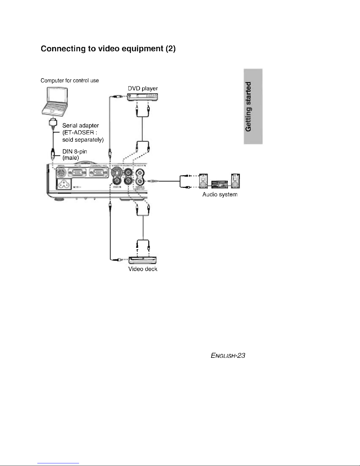
Connecting to video equipment (2)
Audio system
",
DVD player
'1!: ;
y
••
[c::::::::z
I
Video deck
Serial adapter
(ET-ADSER :
sold separately)
DIN 8-pin
(male)
Computer for controluse
ENGLISH-
23
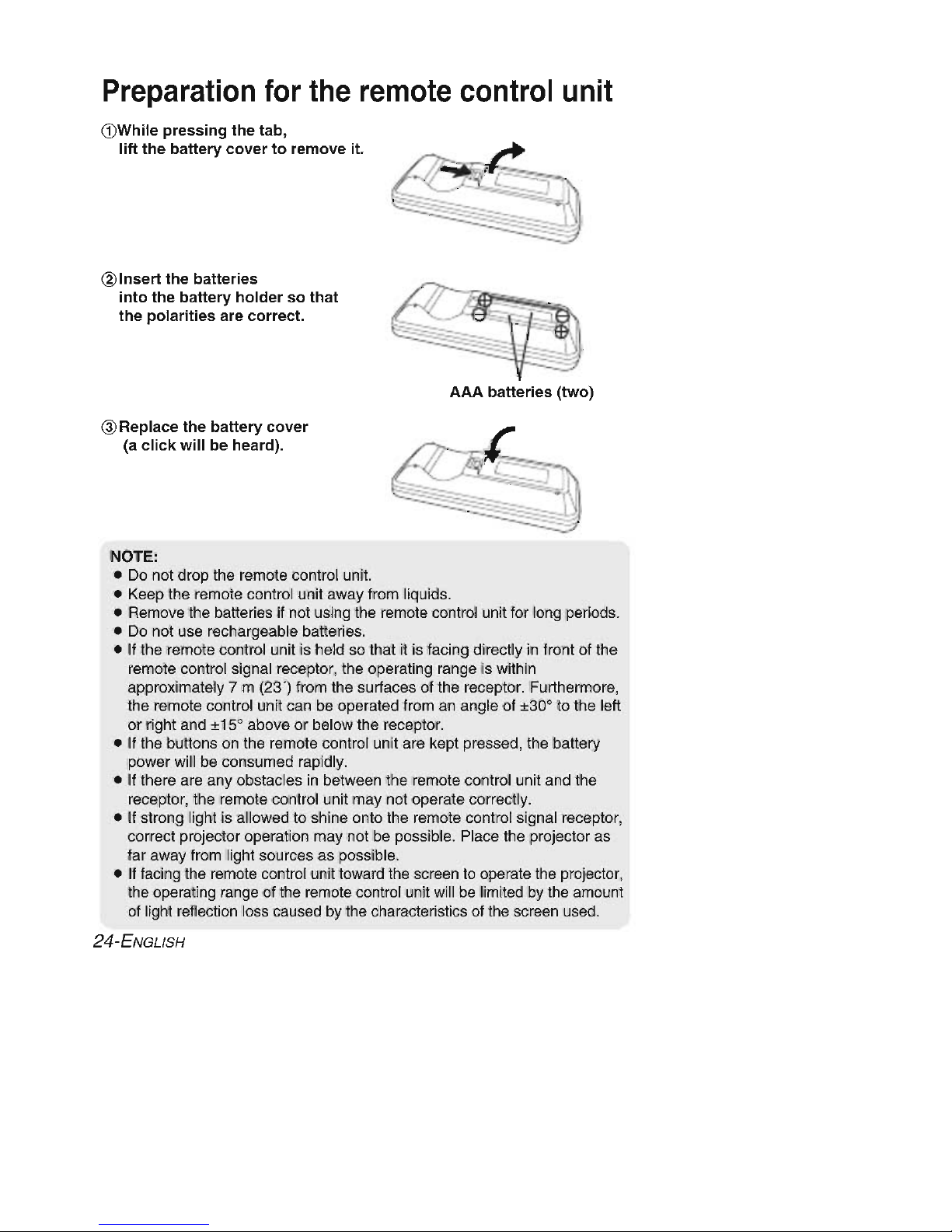
Preparation
for
the
remote
control
unit
(DWhile
pressing
the tab,
Iiflthe
ballery
covertoremove it.
@Insert the
balleries
into
the
ballery
holdersothat
the
polarities
are
correct.
AAA
balleries
(two)
@Replace the
ballery
cover
(a
click
will
be heard).
NOTE:
• Do not drop the remote control unit.
• Keep the remote control unit away from liquids.
• Remove the batteries if not using the remote control unit for long periods.
• Do not use rechargeable batteries.
• If the remote control unit is held so that it is facing directly in front of the
remote control signal receptor, the operating range is within
approximately 7 m (23') from the surfaces of the receptor. Furthermore,
the remote control unit can be operated from an angle of
±30' to the lell
or right and
±15' above or below the receptor.
• If the buttons on the remote control unit are kept pressed, the battery
power will be consumed rapidly.
• If there are any obstacles in between the remote control unit and the
receptor, the remote control unit may not operate correctly.
• If strong light is allowed to shine onto the remote control signal receptor,
correct projector operation may not be possible. Place the projector as
far away from light sources as possible.
• If facing the remote control unit toward the screen to operate the projector,
the operating range of the remote control unit will be limited by the amount
of light reflection loss caused by the characteristics of the screen used.
24-ENGLISH

ENGLISH-25
 Loading...