

Page 1
ENGLISH
Before operating this product, please read the instructions carefully and save this
manual for future use.
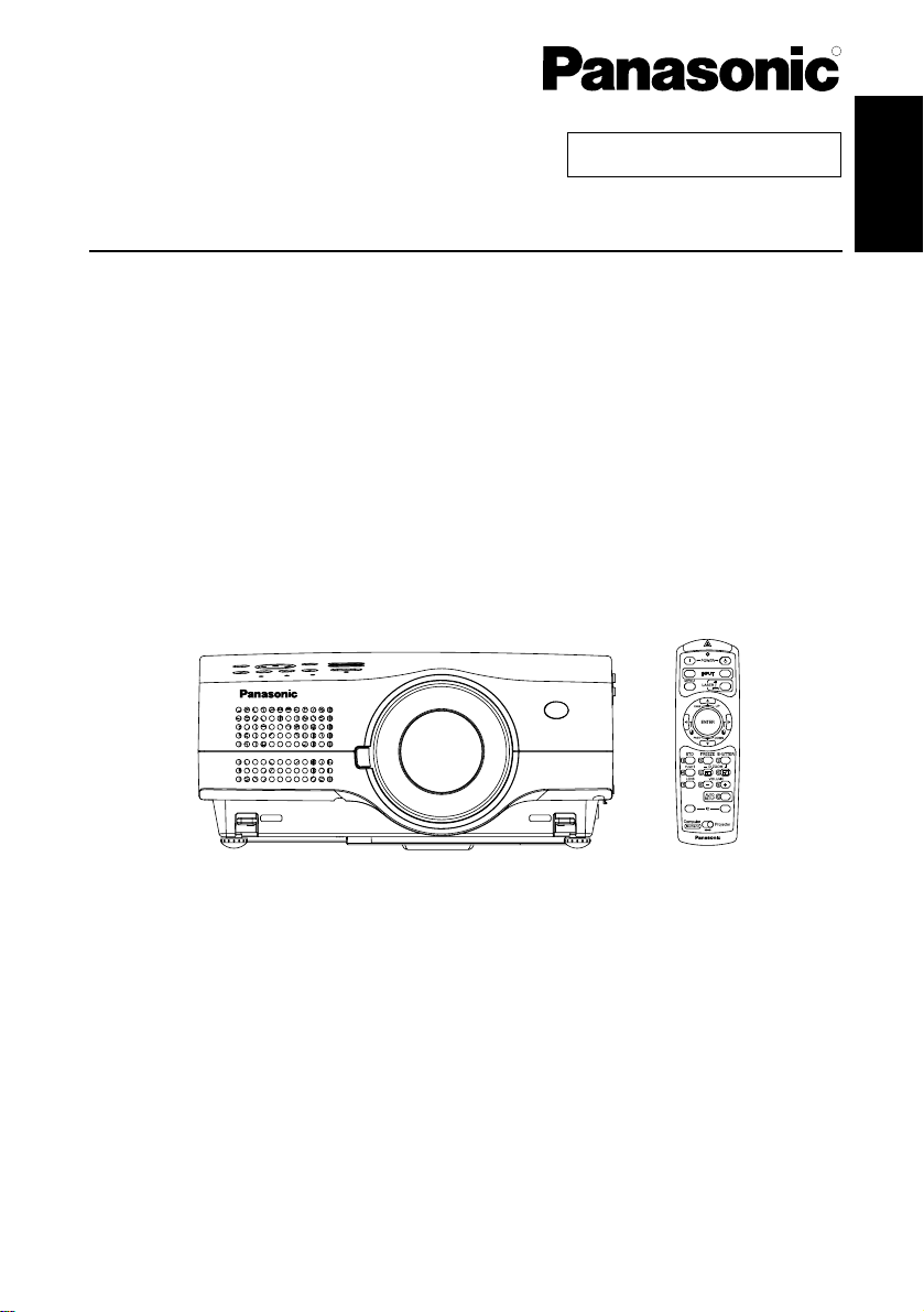
LCD Projector
Operating Instructions
Model No. PT-L785U
TQBJ 0150
Commercial Use
R
RGB
ALL SET
VIDEO
A
Page 2
2-ENGLISH
IMPORTANT SAFETY NOTICE
Dear Panasonic Customer:
This instruction booklet provides all the necessary operating information that you
might require. We hope it will help you to get the most out of your new product,
and that you will be pleased with your Panasonic LCD projector.
The serial number of your product may be found on its bottom. You should note
it in the space provided below and retain this booklet in case service is required.
Model number: PT-L785U
Serial number:
WARNING:
TO REDUCE THE RISK OF FIRE OR ELECTRIC SHOCK, DO
NOT EXPOSE THIS PRODUCT TO RAIN OR MOISTURE.
The lightning flash with arrowhead symbol, within an
equilateral triangle, is intended to alert the user to the
presence of uninsulated “dangerous voltage” within the
product’s enclosure that may be of sufficient magnitude to
constitute a risk of electric shock to persons.
The exclamation point within an equilateral triangle is
intended to alert the user to the presence of important
operating and maintenance (servicing) instructions in the
literature accompanying the product.
Power Supply: This LCD Projector is designed to operate on 100 V – 240 V, 50 Hz/60
Hz AC, house current only.
CAUTION: The AC power cord which is supplied with the projector as an accessory can
only be used for power supplies up to 125 V, 7 A. If you need to use higher
voltages or currents than this, you will need to obtain a separate 250 V
power cord. If you use the accessory cord in such situations, fire may result.
CAUTION:
This equipment is equipped with a three-pin grounding-type power
plug. Do not remove the grounding pin on the power plug. This
plug will only fit a grounding-type power outlet. This is a safety
feature. If you are unable to insert the plug into the outlet, contact
an electrician. Do not defeat the purpose of the grounding plug.
Do not remove
Page 3

ENGLISH-3
Preparation
WARNING:
This equipment has been tested and found to comply with the limits for a
Class B digital device, pursuant to Part 15 of the FCC Rules. These limits
are designed to provide reasonable protection against harmful interference
in a residential installation. This equipment generates, uses and can
radiate radio frequency energy and, if not installed and used in accordance
with the instructions, may cause harmful interference to radio
communications. However, there is no guarantee that interference will not
occur in a particular installation. If this equipment does cause harmful
interference to radio or television reception, which can be determined by
turning the equipment off and on, the user is encouraged to try to correct
the interference by one or more of the following measures:
– Reorient or relocate the receiving antenna.
– Increase the separation between the equipment and receiver.
– Connect the equipment into an outlet on a circuit different from that to
which the receiver is connected.
– Consult the dealer or an experienced radio/TV technician for help.
FCC CAUTION: To assure continued compliance, use only shielded
interface cables when connecting to computers or
peripheral devices.
Any unauthorized changes or modifications to this
equipment will void the users authority to operate.
WARNING:
B Not for use in a computer room as defined in the Standard for the
Protection of Electronic Computer/Data Processing Equipment,
ANSI/NFPA 75.
Declaration of Conformity
Model Number: PT-L785U
Trade Name: Panasonic
Responsible party: Matsushita Electric Corporation of America.
Address: One Panasonic Way Secaucus New Jersey 07094
Telephone number: 1-800-528-8601 or 1-800-222-0741
Email: pbtsservice@panasonic.com
This device complies with Part 15 of the FCC Rules, Operation is subject to
the following two conditions: (1) This device may not cause harmful
interference, and (2) this device must accept any interference received,
including interference that may cause undesired operation.
Page 4

4-ENGLISH
Contents
Preparation
IMPORTANT SAFETY NOTICE ...2
Precautions with regard to safety
...5
Accessories .................................9
Before use..................................10
Location and function of each part
...12
Getting started
Setting-up...................................18
Projection methods, Projector
position, Projection distances
Connections...............................20
Connecting to video equipment,
Connecting to computer
Preparation for the remote
control unit..............................22
Setting the projector ID number
for remote control unit...........23
Basic operation
Turning on the power................24
Turning off the power................26
Useful functions
Correcting the image position
automatically...........................28
Turning off the picture and sound
momentarily............................29
Pausing a picture.......................29
Enlarging the picture.................30
Adjusting the volume................30
Adjusting the zoom and focus...31
Useful functions of the remote
control unit..............................32
Laser beam pointer, Wireless mouse
Adjustments and settings
On-screen menus ......................34
Menu screens, Menu operation guide,
Returning a setting to the factory default
Adjusting the picture.................39
PICTURE MODE, CONTRAST,
BRIGHT, COLOR, TINT, SHARPNESS,
COLOR TEMP., Noise Reduction (NR),
WHITE BALANCE R/G/B, TV-SYSTEM,
Projecting sRGB-compatible pictures
Adjusting the position...............42
POSITION, DOT CLOCK, CLOCK
PHASE, KEYSTONE, OSD
POSITION, ASPECT, RESIZING,
AUTO SETUP, FRAME LOCK
Audio adjustment ......................46
VOLUME, MUTE
Changing the display language
...46
Option settings ..........................47
OSD, AUTO SEARCH, AUTO SIGNAL, RGB2
SELECT, RGB/YP
BPR, VGA60/480p, BACK
COLOR, CINEMA REALITY, FRONT/REAR,
DESK/CEILING, FAN CONTROL, LAMP
POWER, LAMP RUN TIME, FUNC 1,
CONTROL KEY, AUTO POWER OFF, SET ID
Adjusting the lens .....................50
ZOOM/FOCUS, LENS SELECT
Network setup............................50
Setting up the security function
...51
PASSWORD SETTING, CHANGE
PASSWORD, TEXT DISPLAY,
CHANGE TEXT, LOGO DISPLAY,
LOGO CLEAR, LOGO CAPTURE
Care and maintenance
When the TEMP indicator and the
LAMP indicator are illuminated
...54
Cleaning and replacing the air filter
...56
Replacing the lamp unit............57
Before calling for service..........60
Cleaning and maintenance.......61
Others
Using the cable cover ...............62
Putting the mains lead and remote
control unit away, Covering the
connector panel
Replacing the projection lens...64
Projection distance for each
projection lens (sold separately)
Specifications ............................68
Appendix ....................................70
List of compatible signals, Using the
REMOTE connector, Using the SERIAL
connector, Pin assignments, Projection
dimensions calculation methods
Dimensions ................................76
Trademark acknowledgements
...76
NOTES IMPORTANTES
CONCERNANT LA SECURITE..77
Précautions de sécurité
.............
78
Avant l’utilisation
.........................
82
Remplacement du bloc de lampe
...
84
Page 5

ENGLISH-5
Preparation
Precautions with regard to safety
WARNING
If you notice smoke, strange smells or noise coming from the projector,
disconnect the power cord plug from the wall outlet.
B Do not continue to use the projector in such cases, otherwise fire or
electric shocks could result.
B Check that no more smoke is coming out, and then contact an Authorized
Service Center for repairs.
B Do not attempt to repair the projector yourself, as this can be dangerous.
Do not install this projector in a place which is not strong enough to
take the full weight of the projector.
B If the installation location is not strong enough, it may fall down or tip over,
and severe injury or damage could result.
Installation work (such as ceiling suspension) should only be carried
out by a qualified technician.
B If installation is not carried out correctly, there is the danger that injury or
electric shocks may occur.
If foreign objects or water get inside the projector, or if the projector is
dropped or the cabinet is broken, disconnect the power cord plug from
the wall outlet.
B Continued use of the projector in this condition may result in fire or electric
shocks.
B Contact an Authorized Service Center for repairs.
Do not overload the wall outlet.
B If the power supply is overloaded (for example, by using too many
adapters), overheating may occur and fire may result.
Do not remove the cover or modify it in any way.
B High voltages can cause fire or electric shocks.
B For any inspection, adjustment and repair work, please contact an
Authorized Service Center.
Clean the power cord plug regularly to prevent it from becoming
covered in dust.
B If dust builds up on the power cord plug, the resulting humidity can
damage the insulation, which could result in fire. Pull the power cord plug
out from the wall outlet and wipe it with a dry cloth.
B If not using the projector for an extended period of time, pull the power
cord plug out from the wall outlet.
Page 6

6-ENGLISH
Do not do anything that might damage the power cord or the power cord
plug.
B Do not damage the power cord, make any modifications to it, place it near
any hot objects, bend it excessively, twist it, pull it, place heavy objects on
top of it or wrap it into a bundle.
B If the power cord lead is used while damaged, electric shocks, short-
circuits or fire may result.
B Ask an Authorized Service Center to carry out any repairs to the power
cord that might be necessary.
Do not handle the power cord plug with wet hands.
B Failure to observe this may result in electric shocks.
Insert the power cord plug securely into the wall outlet.
B If the plug is not inserted correctly, electric shocks or overheating could
result.
B Do not use plugs which are damaged or wall outlets which are coming
loose from the wall.
Do not place the projector on top of surfaces which are unstable.
B If the projector is placed on top of a surface which is sloped or unstable, it
may fall down or tip over, and injury or damage could result.
Do not place the projector into water or let it become wet.
B Failure to observe this may result in fire or electric shocks.
Do not place liquid containers on top of the projector.
B If water spills onto the projector or gets inside it, fire or electric shocks
could result.
B
If any water gets inside the projector, contact an Authorized Service Center
.
Do not insert any foreign objects into the projector.
B Do not insert any metal objects or flammable objects into the projector or
drop them onto the projector, as doing so can result in fire or electric
shocks.
Keep the batteries out of the reach of infants.
B If the batteries are swallowed, death by suffocation may result. If you
believe that the batteries may have been swallowed, seek medical advice
immediately.
Do not allow the + and - terminals of the batteries to come into contact
with metallic objects such as necklaces or hairpins.
B Failure to observe this may cause the batteries to leak, overheat, explode
or catch fire.
B Store the batteries in a plastic bag and keep them away from metallic
objects.
During a thunderstorm, do not touch the projector or the cable.
B Electric shocks can result.
Do not use the projector in a bath or shower.
B Fire or electric shocks can result.
Page 7

ENGLISH-7
Preparation
Do not look into the lens while the projector is being used.
B Strong light is emitted from the projector’s lens. If you look directly into this
light, it can hurt and damage your eyes.
B Be especially careful not to let young children look into the lens. In
addition, turn off the power and disconnect the power cord plug when you
are away from the projector.
Keep the remote control unit out of the reach of children, and do not
look into the laser beam or point it towards other people.
B If the laser beam which is emitted by the remote control unit transmitter is
pointed directly into the eyes, it may cause visual ability to be impaired.
Do not place your hands or other objects close to the air outlet port.
B Heated air comes out of the air outlet port. Do not place your hands or
face, or objects which cannot withstand heat close to this port, otherwise
burns or damage could result.
Replacement of the lamp unit should only be carried out by a qualified
technician.
B The lamp unit has high internal pressure. If improperly handled, explosion
might result.
B The lamp unit can easily become damaged if struck against hard objects
or dropped, and injury or malfunctions may result.
When replacing the lamp, allow it to cool for at least one hour before
handling it.
B The lamp cover gets very hot, and contact with it can cause burns.
Before replacing the lamp, be sure to disconnect the power cord plug
from the wall outlet.
B Electric shocks or explosions can result if this is not done.
Caution
Do not cover the air inlet port or the air outlet port.
B Doing so may cause the projector to overheat, which can cause fire or
damage to the projector.
B Do not place the projector in narrow, badly ventilated places such as
closets or bookshelves.
Do not set up the projector in humid or dusty places or in places where
the projector may come into contact with smoke or steam.
B Using the projector under such conditions may result in fire or electric shocks.
When disconnecting the power cord, hold the plug, not the lead.
B If the power cord itself is pulled, the lead will become damaged, and fire,
short-circuits or serious electric shocks may result.
Always disconnect all cables before moving the projector.
B Moving the projector with cables still attached can damage the cables,
which could cause fire or electric shocks to occur.
Page 8

8-ENGLISH
Do not place any heavy objects on top of the projector.
B Failure to observe this may cause the projector to become unbalanced
and fall, which could result in damage or injury.
Do not short-circuit, heat or disassemble the batteries or place them
into water or fire.
B Failure to observe this may cause the batteries to overheat, leak, explode
or catch fire, and burns or other injury may result.
When inserting the batteries, make sure the polarities (+ and -) are
correct.
B If the batteries are inserted incorrectly, they may explode or leak, and fire,
injury or contamination of the battery compartment and surrounding area
may result.
Use only the specified batteries.
B If incorrect batteries are used, they may explode or leak, and fire, injury or
contamination of the battery compartment and surrounding area may
result.
Do not mix old and new batteries.
B If the batteries are inserted incorrectly, they may explode or leak, and fire,
injury or contamination of the battery compartment and surrounding area
may result.
Insulate the battery using tape or similar before disposal.
B If the battery comes into contact with metallic objects or other batteries, it
may catch fire or explode.
Do not put your weight on this projector.
B You could fall or the projector could break, and injury may result.
B Be especially careful not to let young children stand or sit on the projector.
Do not lift up the projector by holding the cable cover.
B Failure to observe this may cause the cable cover to come off and the
projector might fall, which could result in injury.
Disconnect the power cord plug from the wall outlet as a safety
precaution before carrying out any cleaning.
B Electric shocks can result if this is not done.
Ask an Authorized Service Center to clean inside the projector at least
once a year.
B If dust is left to build up inside the projector without being cleaned out, it
can result in fire or problems with operation.
B It is a good idea to clean the inside of the projector before the season for
humid weather arrives. Ask your nearest Authorized Service Center to
clean the projector when required. Please discuss with the Authorized
Service Center regarding cleaning costs.
We are constantly making efforts to preserve and maintain a clean
environment. Please take non repairable units back to your dealer or a
recycling company.
Page 9
ENGLISH-9
Preparation
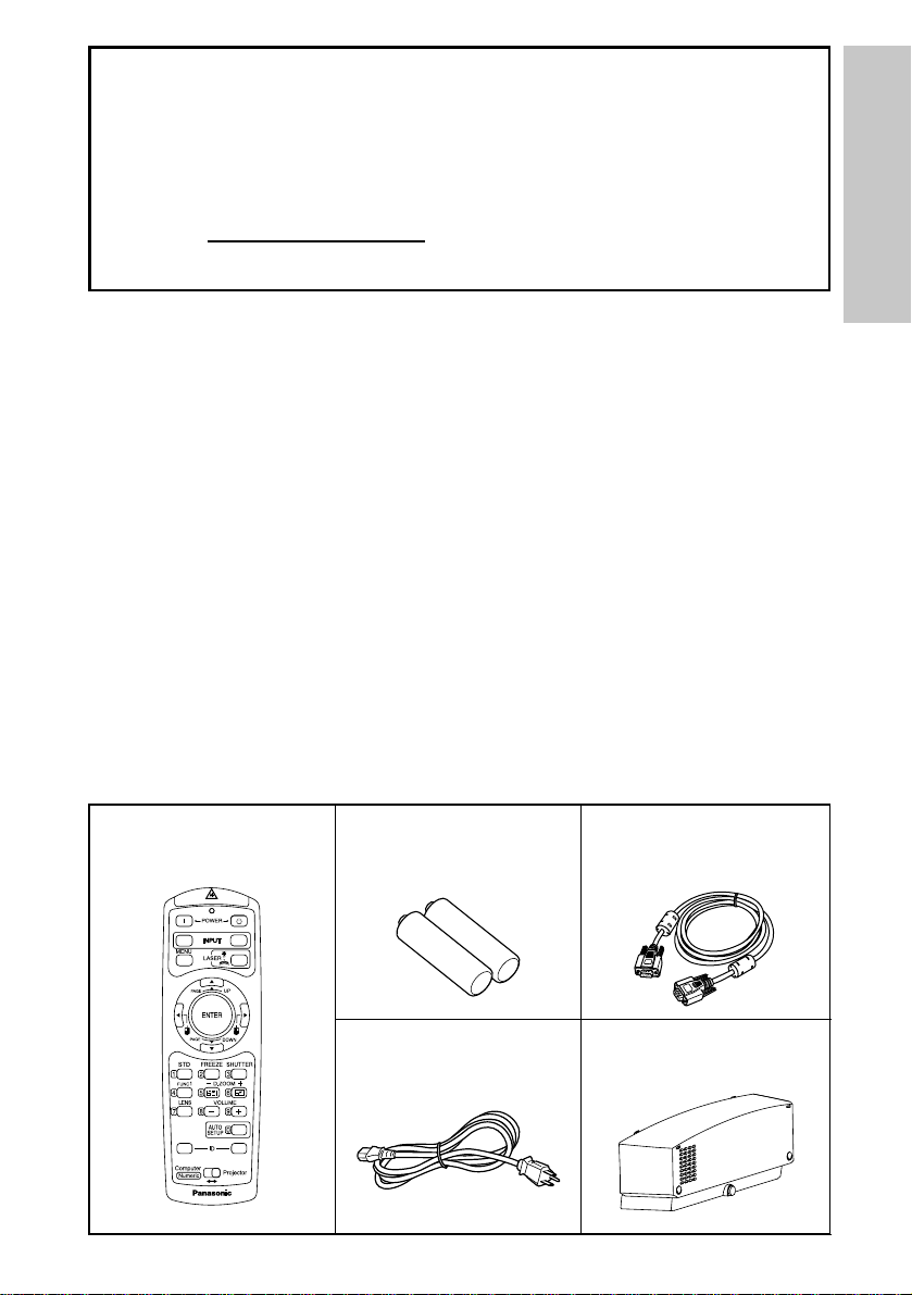
Remote control unit
(N2QAEA000022 x1)
AAA batteries for
remote control unit (x2)
RGB signal cable
[3.0 m (9´10˝),
K1HB15FA0001 x1]
Accessories
Check that all of the accessories shown below have been included with your
projector.
VIDEO
RGB
ALL SET
A
Power cord
(K2CG3FZ00008 x 1)
Cable cover
(TXFKR01VJX7 x1)
NOTICE:
B This product has a High Intensity Discharge (HID) lamp that contains a
small amount of mercury. It also contains lead in some components.
Disposal of these materials may be regulated in your community due to
environmental considerations. For disposal or recycling information
please contact your local authorities, or the Electronics Industries
Alliance: <http://www.eiae.org.>
Page 10

10-ENGLISH
Before use
Caution when moving the projector
Be sure to attach the lens cover before moving the projector.
The projection lens is extremely susceptible to vibration and shocks. Be
careful not to subject it to excessive vibration and shock when moving the
projector.
Cautions regarding setting-up
Avoid setting up in places which are subject to vibration or shocks.
The internal parts can be damaged, which may cause malfunctions or
accidents.
Do not set up the projector near high-voltage power lines or near
motors.
The projector may be subject to electromagnetic interference.
If installing the projector to the ceiling, ask a qualified technician to
carry out all installation work.
You will need to purchase the separate installation kit (Model No.ET-PK780).
Furthermore, all installation work should only be carried out by a qualified
technician.
If using this projector at high elevations (above 1 400 m), set the “FAN
CONTROL” to “HIGH”. (Refer to page 48.)
Failure to observe this may result in malfunctions.
Page 11

ENGLISH-11
Preparation
Notes on use
In order to get the best picture quality
Draw curtains or blinds over any windows and turn off any lights near the
screen to prevent outside light or light from indoor lamps from shining onto
the screen.
Do not touch the surfaces of the lens with your bare hands.
If the surface of the lens becomes dirty from fingerprints or anything else, this
will be magnified and projected onto the screen. Moreover, when not using
the projector, retract the lens and then cover it with the lens cover.
Screen
Do not apply any volatile substances which may cause discoloration to the
screen, and do not let it become dirty or damaged.
Lamp
The lamp may need to be replaced earlier due to variables such as individual
lamp characteristics, usage conditions and the installation environment,
especially when the projector is subjected to continuous use for more than
10 hours or the power is frequently turned on and off, as the operations that
prevent blackening of the bulb (the action of the halogen cycle) do not work
enough during short periods of time.
Liquid crystal panel
The liquid crystal panel of the projector is built with very high precision
technology to provide fine picture details. Occasionally, a few non-active
pixels may appear on the screen as fixed points of blue, green or red.
Please note that this does not affect the performance of your LCD.
Page 12
12-ENGLISH
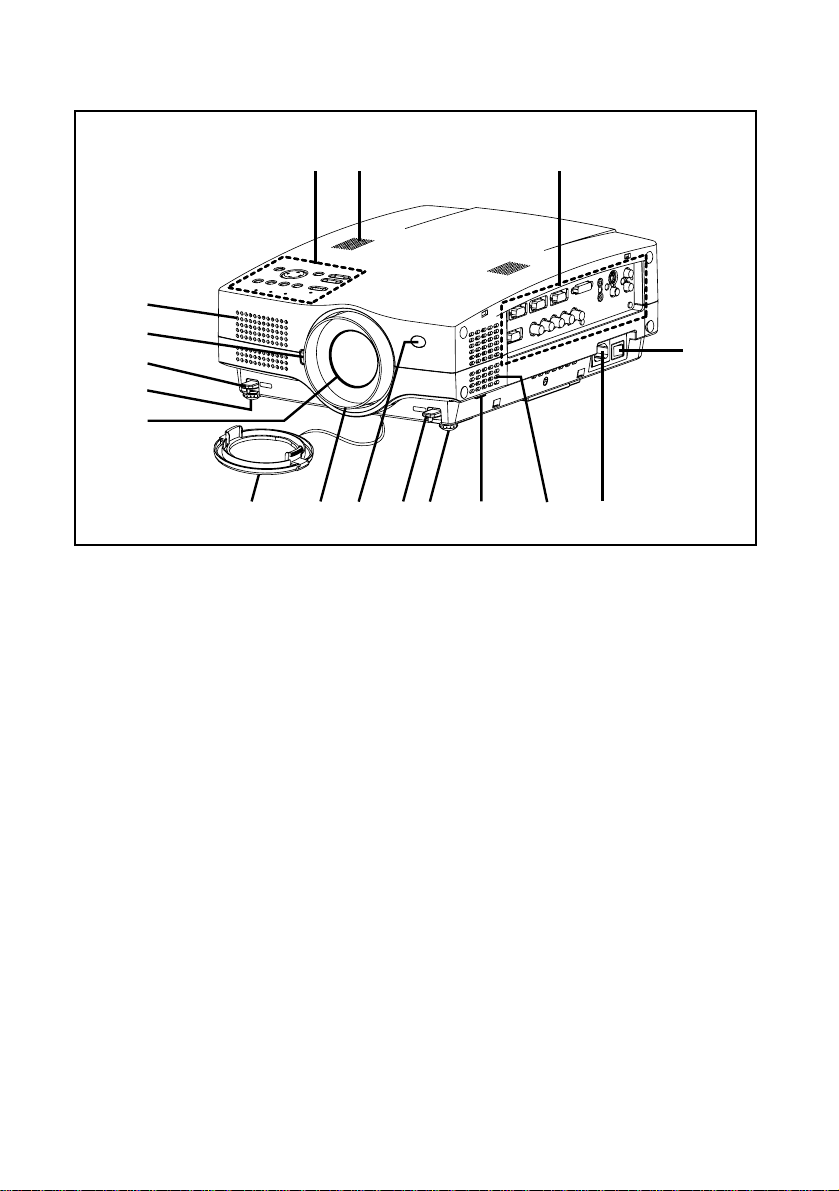
Location and function of each part
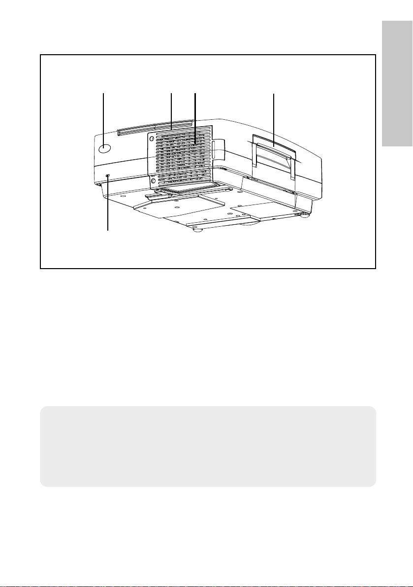
Projector <Top, right and front>
#$
&
(+
+
**)
%
'
0
,-.
/
(
# Projector control panel (page 14)
$ Speaker
% Connector panel (page 16)
& MAIN POWER switch (pages 24 and 26)
' Power input socket (AC IN) (page 24)
The accessory power cord is connected here.
Do not use any power cord other than the accessory power cord.
( Air inlet ports
Do not cover these ports.
) Air filter (page 56)
* Front adjustable legs(L/R) (page 25)
+ Leg adjuster buttons(L/R) (page 25)
These buttons are used to unlock the front adjustable legs. Press to adjust
the angle of tilt of the projector.
, Remote control signal receptor (page 22)
- Focus ring (page 25)
. Lens cover
/ Projection lens
0 Lens release button (page 64)
This button is used when using a projection lens that is sold separately.
Page 13
ENGLISH-13
Preparation
# Remote control signal receptor (page 22)
$ Lamp unit holder (page 57)
% Air outlet port
Do not cover this port.
& Carrying handle
' Security lock
This can be used to connect a commercially-available theft-prevention
cable (manufactured by Kensington). This security lock is compatible with
the Microsaver Security System from Kensington.
WARNING
Do not place your hands or other objects close to the air outlet port.
B Heated air comes out of the air outlet port. Do not place your hands or
face, or objects which cannot withstand heat close to this port, otherwise
burns or damage could result.
Projector <Back and bottom>
NOTE:
B During projection of an image, the cooling fan will operate, emitting a
small noise as it operates. Turning the lamp on or off will cause this
noise to increase a little.
B By using the “OPTION” menu to set “LAMP POWER” to “LOW”, the
operating sound of the fan can be reduced. (Refer to page 48.)
#$%'&
Page 14
14-ENGLISH
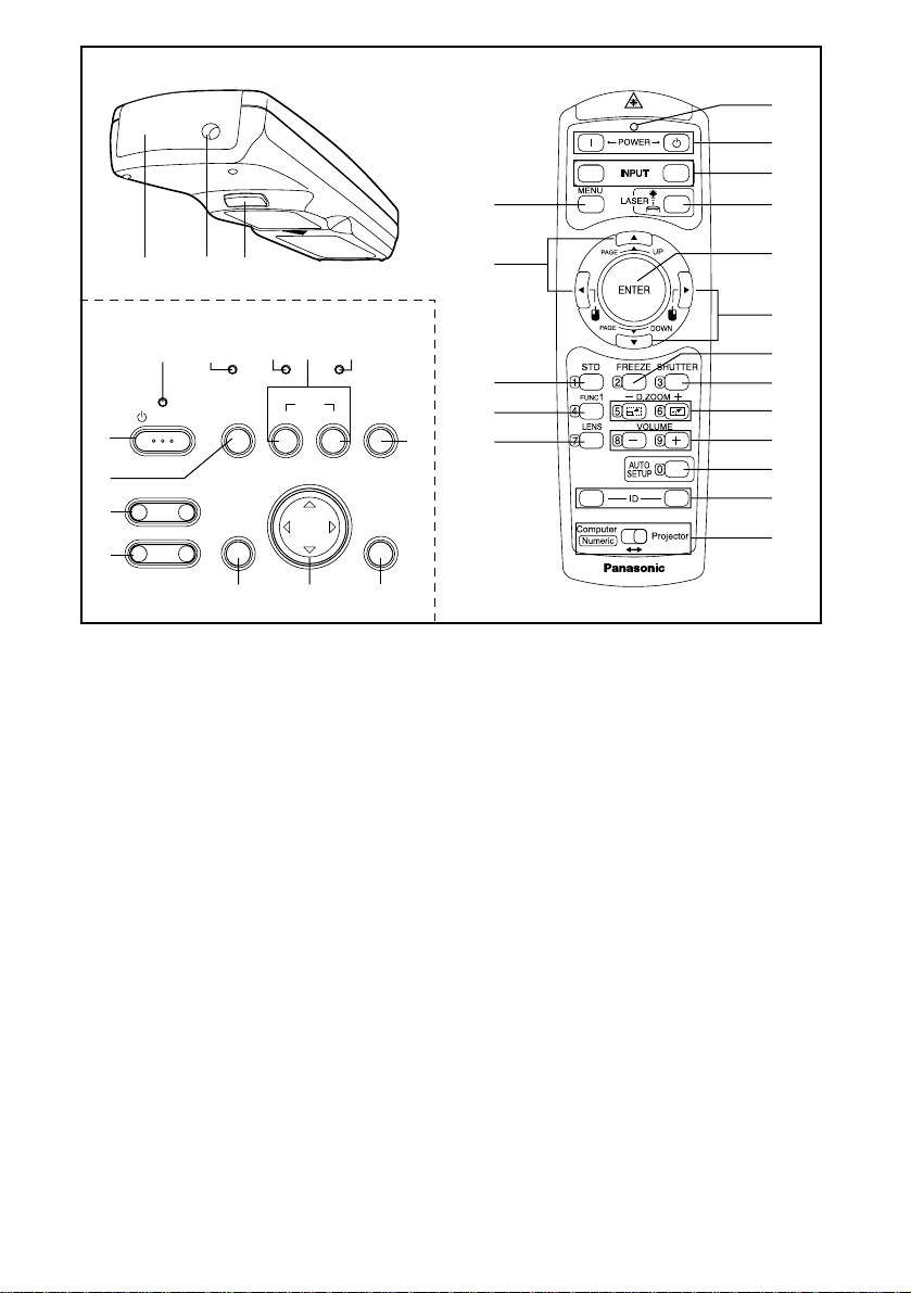
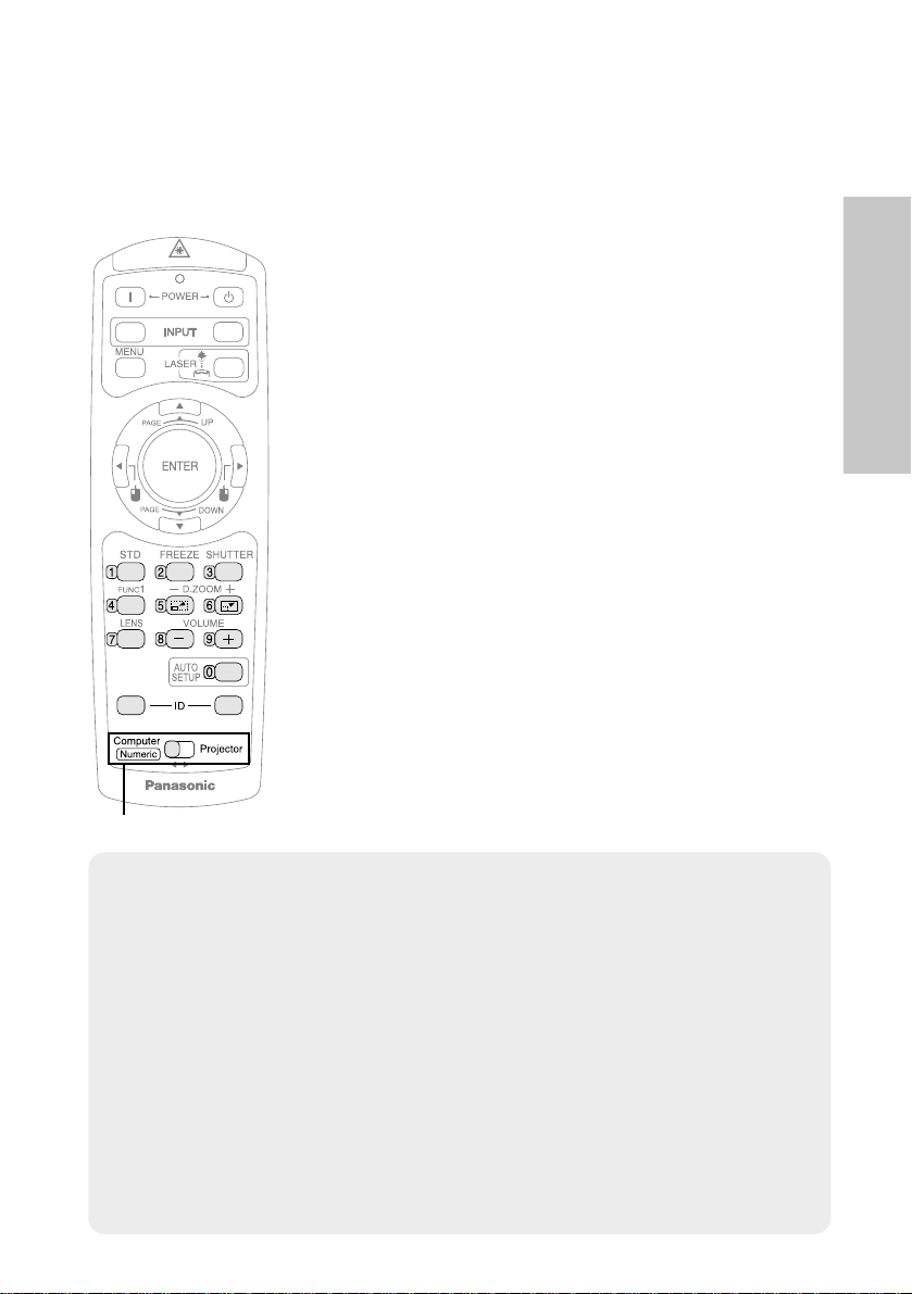
Remote control unit
# Power indicator (pages 24, 26 and 27)
This indicator illuminates red when the MAIN POWER switch is turned on,
and illuminates green when the power is turned on and a picture starts to
be projected.
When the projector is in “WEB STANDBY” mode, this indicator flashes slowly
in red.
$ RGB INPUT indicator (page 27)
This indicator illuminates when a signal is input into the connector that is
selected with the input select buttons.
% LAMP indicator (page 55)
This indicator illuminates when it is time to replace the lamp unit. It flashes
if a circuit abnormality is detected.
& INPUT (RGB, VIDEO) buttons (page 25)
These buttons are used to select the input signals. When “AUTO SEARCH” in the
“OPTION” menu is set to “ON”, the input signal will be detected and selected
automatically by pressing this button for a few seconds. (Refer to page 47.)
' TEMP indicator (page 54)
This indicator illuminates if an abnormally high temperature is detected inside
the projector or around it. If the temperature rises above a certain level, the
power supply will be turned off automatically and the indicator will flash.
( SHUTTER button (page 29)
This button is used to momentarily turn off the picture and sound.
) ENTER button (page 38)
This button is used to accept and to activate items selected in the onscreen menus.
Projector control panel
+
RGB
VIDEO
6
/
&
7
0
12
*
'
&
#
POWER
/
STANDBY(R)
ON(G)
.
– FOCUS +
-
–
ZOOM +
,
%
$
LAMPRGB INPUT
INPUT
MENU
+*
TEMP
RGBVIDEOAUTO SETUP
SHUTTER
ENTER
)
(
3
4
5
A
ALL SET
)
*
8
(
9
:
.
;
<
Page 15

ENGLISH-15
Preparation
*When in computer operating mode, this button on the remote control unit
functions differently. (page 33)
* Arrow (
FGI
and H) buttons (page 37)
These buttons are used to select and adjust items in the on-screen menus.
*When in computer operating mode, these buttons on the remote control
unit function differently. (page 33)
+ MENU button (pages 34 and 37)
This button is used to display the menu screens. When a menu screen is
being displayed, this button can be used to return to a previous screen or
to clear the screen.
, ZOOM +/- buttons (page 25)
These buttons are used to adjust the size of the projected image.
- FOCUS +/- buttons (page 25)
These buttons are used to adjust the focus of the projected image.
. AUTO SETUP button (pages 25 and 28)
If this button is pressed while a picture is being projected, the projection settings
will be adjusted automatically in accordance with the signal being input.
/ POWER button (pages 24 and 26)
These buttons are used to turn the power on and off when MAIN POWER
is turned on.
(For the remote control unit, the “ ” button is for turning on the power and
the “ ” button is for turning off the power.)
0 Laser emitter (page 32)
1 Infrared emitter (page 22)
2 Click button (page 33)
This button can be used when the operating mode select switch is moved
to the left (Computer).
3 STD (standard) button (page 38)
This button is used to reset the projector adjustment values to the factory
default settings.
4 FUNC1 button (pages 43, 46 and 49)
This button can be used for 1) switching on and off the sound volume and
2) entering into the keystone distortion correction mode. Adjust “FUNC1”
in the “OPTION” menu to select which you wish to use.
5 LENS button (page 31)
This button is used to display the zoom and focus adjustment screen.
6 Operation indicator (page 32)
This indicator illuminates while a laser beam is being emitted (while the LASER
button is being pressed). It flashes when any other buttons are being pressed.
7 LASER button (page 32)
A beam of laser light is emitted while this button is being pressed. This
laser beam can be used as a pointer to point to something on the screen.
8 FREEZE button (page 29)
This button is used to momentarily freeze projection so that a still picture is displayed.
9 D.ZOOM +/- buttons (page 30)
These buttons are used to enlarge the projected image.
(continued on next page)
Page 16
16-ENGLISH
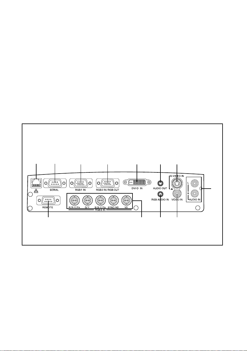
Connector panel
# Wired LAN connector
This connector is used to connect a personal computer to the projector in
order to externally control the projector. (10 Base-T/100 Base-TX)
Refer to the “Network Function Edition” operating instructions for details.
$ SERIAL connector (pages 20, 21 and 72)
This connector is used to connect a personal computer to the projector in
order to externally control the projector. (RS-232C compatible)
% RGB1 IN connector (pages 20 and 21)
This connector is used to input RGB signals and YPBPR signals.
: VOLUME +/- buttons (page 30)
These buttons are used to adjust the volume of the sound that is output
from the projector’s built-in speakers and AUDIO OUT connector. Refer to
page 46 for details on how to adjust the volume using the buttons on the
projector control panel.
; ID SET/ALL button (page 23)
These buttons are used to set the projector ID number into the remote
control unit when using multiple projectors with a single remote control
unit.
< Operating mode (Computer, Projector) select switch (page 33)
Move this switch to the left side to use the remote control unit to operate a
computer, and move it to the right side to operate the projector.
(continued from previous page)
$#
& ( )%
'
, - .+
*
Page 17

ENGLISH-17
Preparation
& RGB2 IN/RGB OUT connector (pages 20, 21 and 47)
This connector is used to input or output RGB signals and YPBPR signals.
Adjust “RGB2 SELECT” in the “OPTION” menu to select whether you want
input or output with this connector.
' DVI-D IN connector (page 21)
This connector is used to input DVI-D signals.
( AUDIO OUT connector (pages 20 and 21)
This connector is used to output the audio signals which are input to the
projector. If audio equipment is connected to this connector, no sound will
be output from the built-in speakers.
) S-VIDEO IN connector (pages 20 and 45)
This connector is used to input signals from a S-VIDEO-compatible
equipment such as a video deck. The connector is S1 signal compatible,
and it automatically switches between 16:9 and 4:3 aspect ratios in
accordance with the type of signal being input.
* AUDIO IN L-R connectors (for S-VIDEO/VIDEO) (page 20)
Only one system is provided, so connect the appropriate connectors when
using S-VIDEO or VIDEO.
+ REMOTE connector (page 71)
This connector is used to control the projector from the remote control set
up in wired mode.
, RGB3 IN connector (pages 20 and 21)
This connector is used to input RGB signals and YPBPR signals.
- RGB AUDIO IN connector (pages 20 and 21)
Only one system is provided, so connect the appropriate connector when
using RGB1, RGB2 or RGB3.
. VIDEO IN connector (page 20)
This connector is used to input video signals from a video equipment such
as a video deck.
Page 18
18-ENGLISH
Setting-up
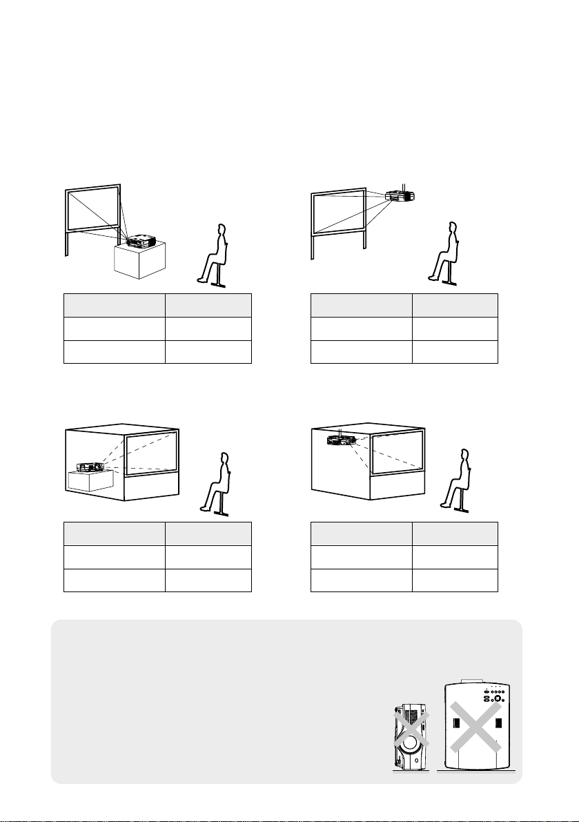
Projection methods
In way of installing projector, any one of the following four projection methods
are used. Select whichever projection method matches the setting-up
method. (The projection method can be set from the “OPTION” menu. Refer
to page 48 for details.)
BFront-desk projection BFront-ceiling projection
BRear-desk projection
(Using a translucent screen)
BRear-ceiling projection
(Using a translucent screen)
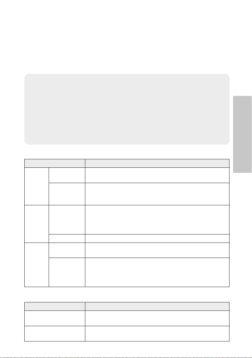
Menu items Setting
FRONT
DESK
FRONT/REAR
DESK/CEILING
Menu items Setting
FRONT
CEILING
FRONT/REAR
DESK/CEILING
Menu items Setting
REAR
DESK
FRONT/REAR
DESK/CEILING
Menu items Setting
REAR
CEILING
FRONT/REAR
DESK/CEILING
NOTE:
B You will need to purchase the separate ceiling bracket (ET-PK780)
when using the ceiling installation method.
B If you set up the projector vertically, it may cause
damage to the projector.
B It is recommended that you set up the projector
in a place that is tilted at less than
±30°. Setting
up the projector in places that are tilted at more
than
±30° may cause malfunctions.
Page 19
ENGLISH-19
Getting started
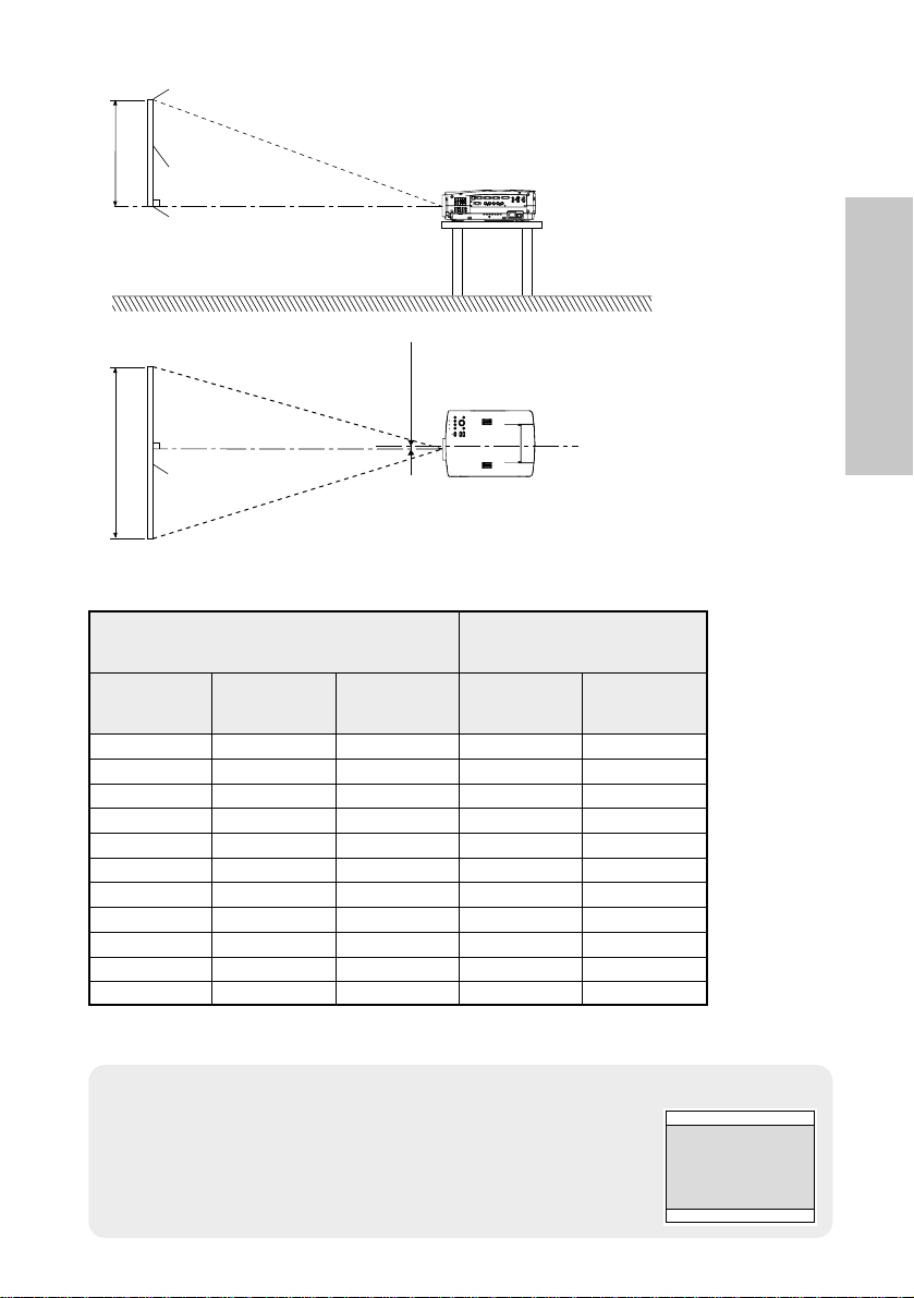
L
L
SH
SW
25 mm
(-31/32˝)
L: Projection distance
SH: Image height
SW:Image width
Top edge of screen
Screen
Bottom edge of screen
Screen
NOTE:
B The dimensions in the table above are approximate.
B If you use the projection distance for the 16:9 screen,
the 4:3 projection image overflows the screen at the top
and bottom.
B
For details about projected image distances, refer to page 75.
Projector position
1.01 m(40˝) 0.61 m(2´) 0.81 m(2´8˝) 1.6 m(5´2˝) 2.0 m(6´6˝)
1.27 m(50˝) 0.76 m(2´6˝) 1.02 m(3´4˝) 2.0 m(6´6˝) 2.6 m(8´6˝)
1.52 m(60˝) 0.91 m(3´) 1.22 m(4´) 2.4 m(7´10˝) 3.1 m(10´2˝)
1.77 m(70˝) 1.07 m(3´6˝) 1.42 m(4´8˝) 2.8 m(9´2˝) 3.6 m(11´9˝)
2.03 m(80˝) 1.22 m(4´) 1.63 m(5´4˝) 3.2 m(10´5˝) 4.2 m(13´9˝)
2.28 m(90˝) 1.37 m(4´6˝) 1.83 m(6´) 3.6 m(11´9˝) 4.7 m(15´5˝)
2.54 m(100˝) 1.52 m(5´) 2.03 m(6´8˝) 4.0 m(13´1˝) 5.3 m(17´4˝)
3.81 m(150˝) 2.29 m(7´6˝) 3.05 m(10´) 6.1 m(20´) 7.9 m(25´11˝)
5.08 m(200˝) 3.05 m(10´) 4.06 m(13´4˝) 8.1 m(26´6˝) 10.6 m(34´9˝)
6.35 m(250˝) 3.81 m(12´6˝) 5.08 m(16´8˝) 10.1 m(33´1˝) 13.3 m(43´7˝)
7.62 m(300˝) 4.57 m(15´) 6.10 m(20´) 16.0 m(52´5˝)
Projection distances*
Screen size (4:3)
Diagonal
length
Height
(SH)
Width
(SW)
Projection distance (L)
Wide
(LW)
Telephoto
(LT)
12.2 m(40´)
*For standard lens which is supplied with the projector. Refer to pages 65 –
67 for details on the projection distances for the optional lenses.
Page 20
20-ENGLISH
Connections
Notes on connections
B
Read the instruction manual for each peripheral device carefully before connecting it.
B
Turn off the power supply for all peripheral devices before making any connections.
B
If the cables necessary for connection are not included with the peripheral device or
available as an option, you may need to prepare a proper cable for the device concerned.
B
If there is a lot of jitter in the video signal, the projected image may flicker. In such
cases, it will be necessary to connect a TBC (time base corrector).
B
Refer to the list on page 70 for details on compatible signals which can be input to
the projector.
B
Only one audio system circuit is available for each of the AUDIO IN L-R connectors for
S-VIDEO/VIDEO signals and the RGB AUDIO IN connector, so if you wish to change
the audio input source, you will need to remove and insert the appropriate plugs.
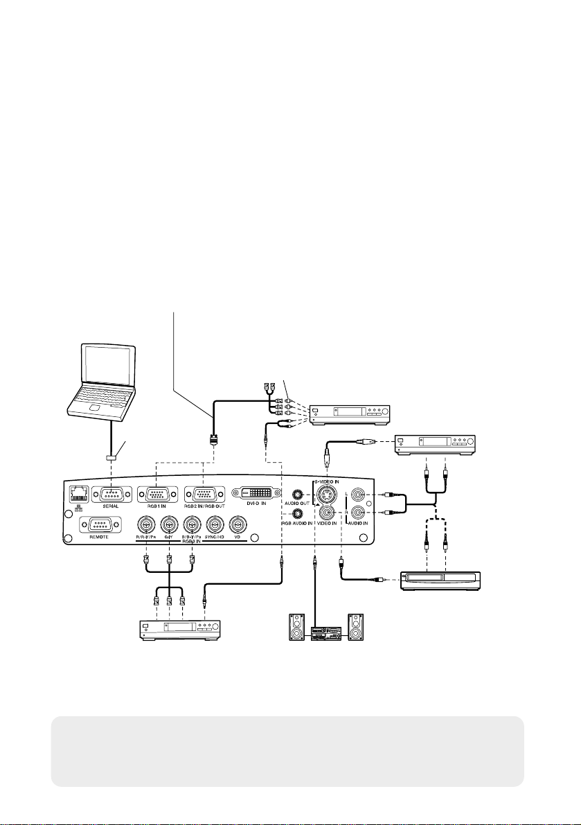
Connecting to video equipment
D-sub 15-pin (male) - BNCx5 (male) adapter cable
Red (connect to PR signal connector)
Blue (connect to PB signal connector)
Green (connect to Y signal connector)
D-sub 9-pin
(male)
DVD player Audio system
Video deck
Computer for
control use
DVD player
Red (connect to PR signal connector)
Blue (connect to PB signal connector)
Green (connect to Y signal connector)
DVD player
(with component
video connectors)
BNC/RCA adapter
NOTE:
B If the signal cables are disconnected or if the power supply for the
computer or video deck is turned off while “D.ZOOM”(digital zoom) is
being used, this function will be cancelled.
Page 21
ENGLISH-21
Getting started
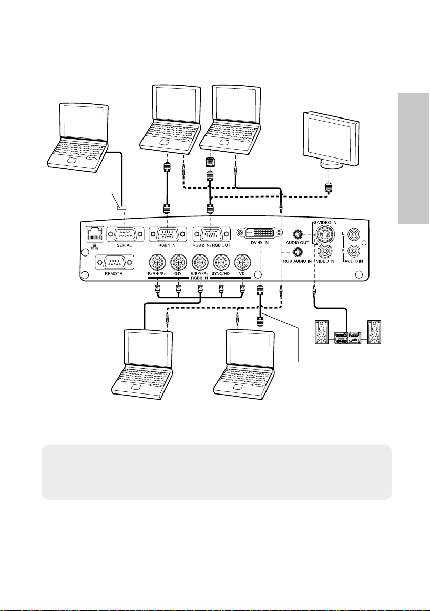
Connecting to computer
1 623 45
ON DIP
D-sub 9-pin
(male)
Computer for
control use
Computer
Monitor
Audio system
Computer
Computer (with
DVI-D OUT connector)
DVI cable
(ET-SCDV03: sold
separately)
NOTE:
B Do not input the signal to the RGB2 IN/RGB OUT connector when
“RGB2 SELECT” in the “OPTION” menu is set to “OUTPUT”. (Refer to
page 47.)
Refer to the “Network Function Edition” operating instructions for
details on connecting the projector to a personal
computer using the wired LAN connector.
Page 22
22-ENGLISH
Preparation for the remote control unit
NOTE:
B Do not drop the remote control unit.
B Keep the remote control unit away from liquids.
B Remove the batteries if not using the remote control unit for long periods.
B Do not use rechargeable batteries.
B If the remote control unit is held so that it is facing directly in front of the
remote control signal receptors on the front or rear of the projector, the
operating range is within approximately 7 m (23´) from the surfaces of
the receptors. Furthermore, the remote control unit can be operated
from an angle of ±30° to the left or right and ±15° above or below the
receptors.
B If there are any obstacles in between the remote control unit and the
receptors, the remote control unit may not operate correctly.
B If strong light is allowed to shine onto the remote control signal receptor,
correct projector operation may not be possible. Place the projector as
far away from light sources as possible.
B
If facing the remote control unit toward the screen to operate the projector,
the operating range of the remote control unit will be limited by the amount
of light reflection loss caused by the characteristics of the screen used.
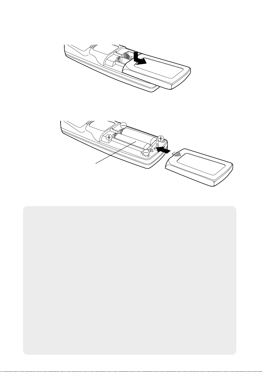
# Open the cover.
AAA batteries
(two)
$ Insert the batteries so that the polarities
are correct, and then close the cover.
Page 23
NOTE:
B If the entered ID number is more than 64, the ID number will return to
the one set before the ID SET button was pressed.
B The ID number setting screen will be canceled if no number is entered
for 5 seconds or if any button except the numeric buttons is pressed.
B If the ID SET button is pressed after a number less than 10 is entered,
the entered number will be cancelled.
B If ID number is set to “ALL” by pressing the ID ALL button, the
projectors can be controlled regardless of their ID number setting.
B The projector cannot be turned on and off from the remote control unit if
the “CONTROLLER ID” does not match the projector ID number. For
more details on projector ID number setting, see page 49.
B The projector ID number in the remote control unit is set to “ALL” by
default. It is therefore not necessary to set a projector ID number when
only one projector is used.
ENGLISH-23
Getting started
Setting the projector ID number for
the remote control unit
When controlling multiple projectors individually or simultaneously with a
single remote control unit, a projector ID number must be set into the remote
control unit as described in the following steps.
# When setting the projector ID number, move
the mode switch to the left side (Numeric).
$ Press the ID SET button on the remote
control unit.
The projector ID number which is currently set
will be displayed on the screen.
% Press the numeric (0 - 9) buttons on the
remote control unit to set the ID number.
The entered ID number will be displayed on the
screen. (You can set from the number 1 to the
number 64.)
B
If the entered ID number is 10 - 64, the ID number
setting will be completed.
B If the ID number entered is less than 10, press
any button other than the numeric buttons or the
ID SET/ALL button, or wait for about 5 seconds
to complete the setting.
VIDEO
RGB
ALL SET
A
Mode switch
Page 24
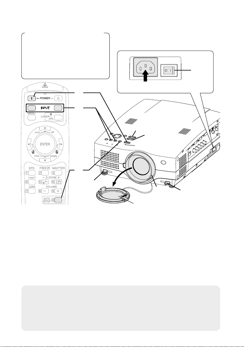
Turning on the power
Before turning on the power
1, Ensure that all peripheral
devices are connected
properly.
2, Connect the accessory power
cord.
3, Remove the lens cover.
Lens cover
Press the MAIN POWER s witc h to turn on the power.
BThe power indicator on the projector will illuminate red.
Press the POWER button.
BThe power indicator on the projector will flash green. After a short
period, the indicator will illuminate green, and a picture will be
projected.
Turn on the power of all connected devices.
BStart the play function of a device such as a DVD player.
NOTE:
B A tinkling sound may be heard when the lamp unit is turned on, but this
is not a sign of a malfunction.
B The projector cannot be turned on and off from the remote control unit
if the “CONTROLLER ID” does not match the projector ID number.
(pages 23 and 49)
#
$
%
24-ENGLISH
$
&
(
'
*
*
)
'
#
Power indicator
Power cord
RGB
VIDEO
A
Page 25
ENGLISH-25
Basic Operation
Press the input select button to select the
input signal.
Follow the procedure below when you set the projector up first, and when
you change the setup place.
Press the AUTO SETUP button to initiate
automatic positioning.
BThe position of the projected image
will be corrected automatically in
accordance with the input signal.
(Refer to page 28 for details.)
B
If the projected image contains
keystone distortion, adjust
“KEYSTONE” in the “POSITION” menu (refer to page 43 for details).
Input select
buttons
Changing
signals
VIDEO
VIDEO
RGB
RGB
VIDEO
S-VIDEO
RGB1
RGB3DVI
RGB2
&
'
Adjusting the angle
BWhile pressing the adjuster buttons,
adjust the forward/back angle of tilt
of the projector. Adjust so that the
projector is as vertical to the screen
as possible.
BA picture will be projected in accordance with the selected input
signal.
BWhen an YPBPR signal is being input, “YPBPR” will be displayed
(when “RGB/YPBPR” in the “OPTION” menu is set to “YPBPR”.
Refer to page 47 for details).
Adjusting the focus
B
Press the FOCUS +/- buttons to adjust the focus of the projected image.
The focus of the projected image can also be adjusted by turning the
focus ring. To make fine adjustments, use the FOCUS +/- buttons.
Adjusting the size
BPress the ZOOM +/- buttons to adjust the size of the projected image.
)
*
(
AUTO SETUP
Page 26
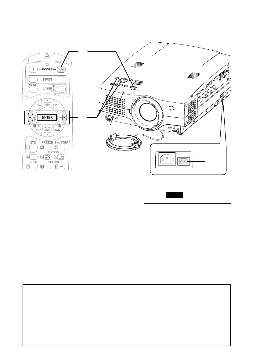
Turning off the power
Press the POWER button.
B“Power OFF” is displayed on the
screen.
Press the Ior Hbutton to select “OK”, and
then press the ENTER button.
BThe lamp unit will switch off and the picture will stop being projected.
(The power indicator on the projector will illuminate orange while the
cooling fan is still operating.)
#
$
26-ENGLISH
VIDEO
RGB
#
$
%
Power indicator
RGB INPUT indicator
Power OFF
OK CANCEL
%
Press the MAIN POWER switch to turn off the
power after the power indicator on the
projector illuminates red.
Direct power off function
You can turn off the MAIN POWER switch and move the projector
immediately after use. The cooling fan will operate by the internal power
supply to cool down the lamp.
B When this function is used, it may take more time for the lamp to turn
back on again compared to when the lamp cools down while the MAIN
POWER switch is ON.
B Do not put the projector in a bag while the cooling fan is operating.
Page 27
ENGLISH-27
Basic Operation
NOTE:
B You can also turn off the power by pressing the POWER button twice or
by holding it down for at least 0.5 seconds.
B When the projector is in standby mode (the power indicator on the
projector is illuminated red), the projector continues to draw approximately
11 W of power even when the cooling fan has stopped.
B
When the projector is in “WEB STANDBY” mode, the cooling fan operates
and the power indicator on the projector flashes slowly in red and the
projector continues to draw approximately 40 W of power. (page 50)
Power indicator
Power indicator status
Red
Illuminated
The projector is in standby mode and image projection
is possible by pressing the POWER button.
A picture is being projected.
The lamp is cooling down after the power is turned
off. (The cooling fan is operating.)
The projector is preparing for projection after the
power is turned on while the power indicator is
illuminated orange. (After a short period, a picture
will be projected.)
The projector is preparing for projection after the
power is turned on while the power indicator is
illuminated red. (After a short period, a picture will be
projected.)
Flashing
The projector is in “WEB STANDBY” mode, and can be
controlled with personal computers via a wired LAN.
(The cooling fan is operating.)
Flashing
slowly
Illuminated
Illuminated
Flashing
Green
Orange
Projector status
RGB INPUT indicator
RGB INPUT indicator status
Illuminated during
standby mode
A signal is being input to one of the RGB1 IN, RGB2
IN or RGB3 IN connectors.
Illuminated during
projection
A signal is being input to the connector selected
using the input select buttons.
Projector status
Page 28

28-ENGLISH
Correcting the image position
automatically
(AUTO SETUP)
The position of the projected image can be corrected automatically in
accordance with the input signal.
Projector control panel
Press the AUTO SETUP button.
(When the edges of the projected image are not visible)
B Automatic positioning
will be carried out.
[
NOTE:
B “AUTO SETUP” does not function when DVI signals are being input.
B When RGB signals are being input, “DOT CLOCK”, and “CLOCK
PHASE” will be adjusted automatically in addition to the position of the
image being corrected (except when the dot clock frequency is 108 MHz
or higher). Refer to page 43 for details.
B If the edges of the projected image are indistinct, or if a dark picture is
being projected, the automatic setup processing may stop automatically
before it is complete. If this happens, project a different picture and then
press the AUTO SETUP button again.
ALL SET
A
RGBVIDEOAUTO SETUP SHUTTER
INPUT
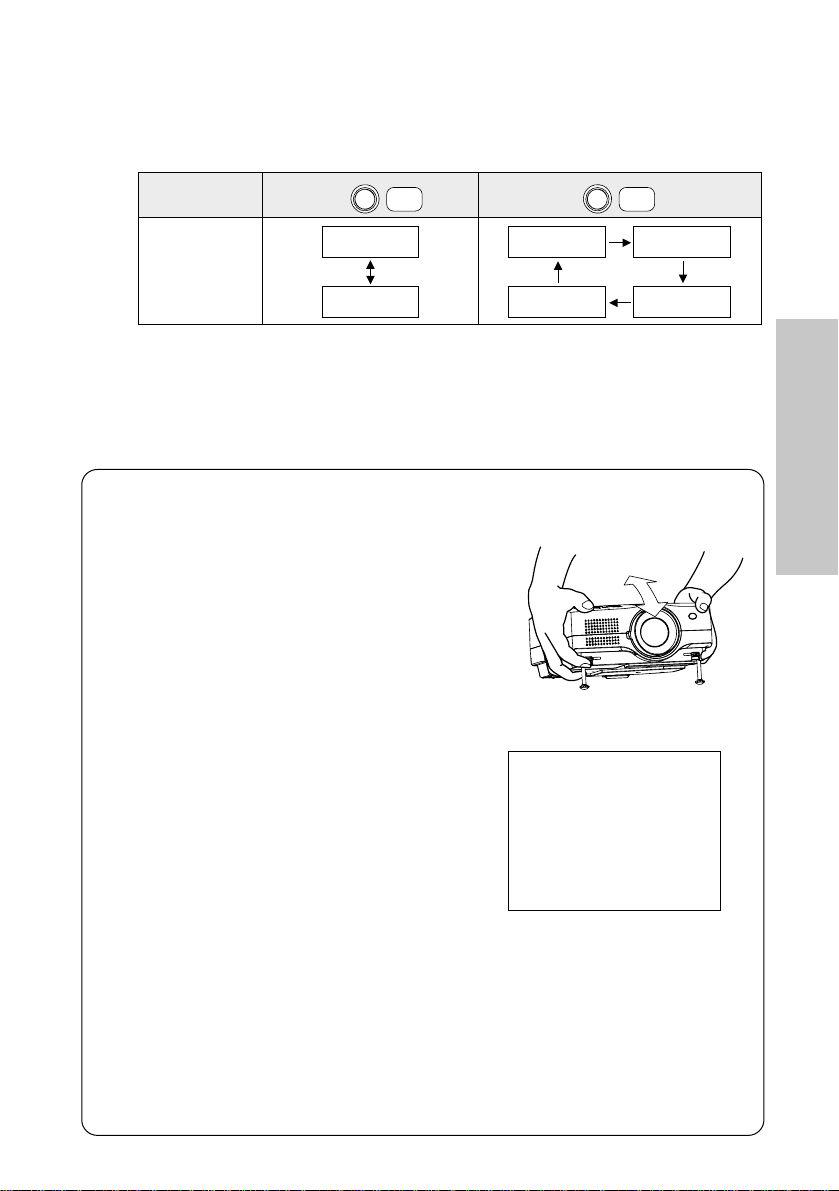
Page 29

ENGLISH-29
Useful functions
Turning off the picture and sound
momentarily (SHUTTER)
The “SHUTTER” function can be used to momentarily turn off the picture and
sound from the projector when the projector is not being used for short
periods of time, such as during breaks in meetings or when carrying out
preparation. The projector uses less power in “SHUTTER” mode than it does
in normal projection mode.
ALL SET
A
Still picture
B The picture being projected will be paused.
B Press the FREEZE button again to cancel the
still picture.
Press the SHUTTER button.
B The picture and sound will be turned off.
B Press any button on either the projector or
remote control unit to return to normal operating
mode.
Press the FREEZE button.
Pausing a picture (FREEZE)
Projector control panel
RGBVIDEOAUTO SETUP SHUTTER
INPUT
ALL SET
A
Page 30

30-ENGLISH
VIDEO
RGB
A
B The picture will then
be enlarged to 1.5
times the normal size.
The remote control unit functions during D.ZOOM (digital zoom)
Press the F,G,IandHbuttons to move the enlarged area which you want to project.
Press the D.ZOOM +/- buttons to change the enlargement ratio.
Press the MENU button to return to the normal screen.
ALL SET
A
[
Enlarging the picture (D.ZOOM)
Adjusting the volume (VOLUME)
Press the D.ZOOM +/- button.
Press the VOLUME +/- button.
B Press the + button to raise the volume.
B Press the - button to lower the volume.
NOTE:
B The enlargement ratio can be changed within the range of x1 to x4, in
steps of 0.1.
B If the type of signal being input changes while the digital zoom function
is being used, the digital zoom function will be cancelled.
NOTE:
B You can also select “VOLUME” from the
“AUDIO” menu to adjust the volume. (page 46)
Page 31

ENGLISH-31
Useful functions
Adjusting the zoom and focus (LENS)
Press the LENS button.
VIDEO
RGB
ALL SET
A
B Press the I or H button to adjust the size of
the projected image.
B Press the F or G button to adjust the focus of
the projected image.
ZOOM
FOCUS
←→
↑↓
NOTE:
B “ZOOM/FOCUS” in the “LENS” menu is the
same function.
Page 32

32-ENGLISH
Useful functions of the remote control unit
Laser beam pointer
The laser beam emitted from the remote control can be used as a pointer by
pointing forward to the screen.
While the LASER button is being pressed, the laser beam is being emitted
and the operating indicator illuminates.
Do not look into the laser emitter of the remote control unit or point the laser
beam towards other people, otherwise damage to eyes may occur.
Caution
B Use of controls or adjustments or performance of procedures
other than those specified herein may result in hazardous
radiation exposure.
B This remote control unit cannot be repaired.
VIDEO
RGB
ALL SET
A
Warning
B DO NOT STARE INTO THE LASER
BEAM OR AIM IT AT ANY PERSON'S
EYE. LASER RADIATION CAN CAUSE
SERIOUS INJURY TO THE HUMAN EYE.
Laser transmitter window
Page 33

ENGLISH-33
Useful functions
Wireless mouse
By connecting the wireless mouse receiver (ET-RMRC2, sold separately) to
a personal computer, you can use the remote control unit as a personal
computer mouse.
PAGE UP button
PAGE DOWN button
ENTER button
Right click button
Click button
Mode switch
(Computer/Projector)
Mode switch (Computer/Projector)
Move the mode switch to the
“Computer” position.
B PAGE UP button
Functions as the Page Up
button on
a personal computer
keyboard.
B PAGE DOWN button
Functions as the Page Down
button on
a personal computer
keyboard.
B ENTER button
Pressing the upper, lower, left
and right edges of this button
can move the cursor up, down,
left and right.
B Right click button
This button functions as the right
button on
a personal computer
mouse.
B Click button
This button functions as the left
button on
a personal computer
mouse.
VIDEO
RGB
ALL SET
A
Click button
Page 34

34-ENGLISH
32
32
32
32
32
PICTURE
PICTURE MODE
CONTRAST
BRIGHT
SHARPNESS
COLOR TEMP.
WHITE BALANCE R
WHITE BALANCE G
WHITE BALANCE B
STANDARD
SELECT:[^][@]
ADJUST:[{][}]
ENTER:[ENTER]
ESC:[MENU]
STANDARD
STANDARD
6
PICTURE menu (page 39)
When an RGB/DVI signal is being
input
On-screen menus
Menu screens
The various settings and adjustments for this projector can be carried out by
selecting the operations from on-screen menus.
The general arrangement of these menus is shown below.
32
32
32
6
32
1
PICTURE
PICTURE MODE
CONTRAST
BRIGHT
COLOR
TINT
SHARPNESS
COLOR TEMP.
NR
STANDARD
SELECT:[^][@]
ADJUST:[{][}]
ENTER:[ENTER]
ESC:[MENU]
STANDARD
STANDARD
When a YPBPR signal is being input
AUTO
32
32
32
6
32
1
PICTURE
PICTURE MODE
CONTRAST
BRIGHT
COLOR
TINT
SHARPNESS
COLOR TEMP.
NR
TV-SYSTEM
STANDARD
SELECT:[^][@]
ADJUST:[{][}]
ENTER:[ENTER]
ESC:[MENU]
STANDARD
STANDARD
When an S-VIDEO/VIDEO signal is
being input
NOTE:
B Keystone distortion of the on-screen display will not be corrected.
B This projector has unadjustable items and unusable functions
depending on the signal being input.
When an item cannot be adjusted or a function cannot be used, the
corresponding on-screen menu display does not appear, and the item
or function will not work even if the ENTER button is pressed.
Page 35

ENGLISH-35
Adjustments and settings
POSITION
POSITION
DOT CLOCK
CLOCK PHASE
KEYSTONE
OSD POSITION
RESIZING
AUTO SETUP
FRAME LOCK
STANDARD
H: 128 V: 32
H: 0 V: 0
32
16
OFF
OFFONON
TOP LEFT
SELECT:[^][@]
ADJUST:[{][}]
ENTER:[ENTER]
ESC:[MENU]
POSITION menu (page 42)
When an RGB/DVI signal is being
input
POSITION
POSITION
CLOCK PHASE
KEYSTONE
OSD POSITION
ASPECT
RESIZING
AUTO SETUP
STANDARD
H: 64 V: 16
H: 0 V: 0
OFF ON
TOP LEFT
4:3
SELECT:[^][@]
ADJUST:[{][}]
ENTER:[ENTER]
ESC:[MENU]
16
When a YPB
PR signal is being input
POSITION
POSITION
KEYSTONE
OSD POSITION
ASPECT
RESIZING
AUTO SETUP
STANDARD
H: 32 V: 16
H: 0 V: 0
OFF ON
TOP LEFT
4:3
SELECT:[^][@]
ADJUST:[{][}]
ENTER:[ENTER]
ESC:[MENU]
“POSITION”, “DOT CLOCK” and
“CLOCK PHASE” are not displayed
when a DVI signal is being input.
When an S-VIDEO/VIDEO signal is
being input
AUDIO
VOLUME
MUTE
OFF ON
20
SELECT:[^][@]
ADJUST:[{][}]
ENTER:[ENTER]
ESC:[MENU]
AUDIO menu (page 46)
LANGUAGE
SELECT:[^][@][{][}]
SELECT:[{][}]
ESC:[MENU]
ENTER:[ENTER]
ENGLISH
DEUTSCH
FRANÇAIS
ESPAÑOL
ITALIANO
LANGUAGE menu (page 46)
Page 36

36-ENGLISH
OPTION
OSD
AUTO SEARCH
AUTO SIGNAL
RGB2 SELECT
RGB/YP
B
P
R
VGA60/480p
BACK COLOR
CINEMA REALITY
NEXT PAGE @
OFF
OFF
OFF
INPUT
RGB
VGA60
BLUE
OFF
ON
ON
ON
OUTPUT
YP
B
P
R
480p
BLACK
ON
SELECT:[^][@]
ADJUST:[{][}] ESC:[MENU]
OPTION menu (page 47)
10 H
OPTION
PREVIOUS PAGE ^
FRONT/REAR
DESK/CEILING
FAN CONTROL
LAMP POWER
LAMP RUN TIME
FUNC1
CONTROL KEY
SET ID
AUTO POWER OFF
FRONT
DESK
STANDARD
LOW
MUTE
OFF
REAR
CEILING
HIGH
HIGH
KEYSTONE
ON
SELECT:[^][@]
ADJUST:[{][}]
ENTER:[ENTER]
ESC:[MENU]
DISABLE
ALL
OFF
OFFONON
NETWORK
NETWORK
HOSTNAME
WEB CONTROL
WEB STANDBY
WEB PASSWORD
MAC ADDRESS
SELECT:[^][@] ENTER:[ENTER]
ESC:[MENU]
PROJECTOR
00:0B:97:41:00:00
LAN1
NETWORK menu (page 50)
INVALID
OFF
OFF
VALID
ON
ON
SECURITY
PASSWORD SETTING
CHANGE PASSWORD
TEXT DISPLAY
CHANGE TEXT
LOGO DISPLAY
LOGO CLEAR
LOGO CAPTURE
SELECT:[^][@][{][}]
ADJUST:[{][}]
ENTER:[ENTER]
ESC:[MENU]
SECURITY menu (page 51)
LENS
ZOOM/FOCUS
LENS SELECT
STANDARD
SELECT:[^][@] ENTER:[ENTER]
ESC:[MENU]
“RGB/YPBPR” is displayed when
an RGB/YPBPR
signal is being
input.
LENS menu (page 50)
Page 37

ENGLISH-37
Adjustments and settings
# Press the MENU button.
The menu screen will be displayed.
$ Press the Ior Hbutton to select a menu.
The selected menu screen will then be displayed.
(Example: “POSITION” menu)
% Press the Gbutton to accept the selection.
You can select an item here. The selected item is
shown in yellow.
Projector control panel
Menu operation guide
32
32
32
32
32
PICTURE
PICTURE MODE
CONTRAST
BRIGHT
SHARPNESS
COLOR TEMP.
WHITE BALANCE R
WHITE BALANCE G
WHITE BALANCE B
STANDARD
SELECT:[^][@]
SELECT:[{][}]
ENTER:[ENTER]
ESC:[MENU]
STANDARD
STANDARD
6
POSITION
POSITION
DOT CLOCK
CLOCK PHASE
KEYSTONE
OSD POSITION
RESIZING
AUTO SETUP
FRAME LOCK
STANDARD
H: 128 V: 32
H: 0 V: 0
32
16
OFF
OFFONON
TOP LEFT
SELECT:[^][@]
SELECT:[{][}] ESC:[MENU]
POSITION
POSITION
DOT CLOCK
CLOCK PHASE
KEYSTONE
OSD POSITION
RESIZING
AUTO SETUP
FRAME LOCK
STANDARD
H: 128 V: 32
H: 0 V: 0
32
16
OFF
OFFONON
TOP LEFT
SELECT:[^][@]
ADJUST:[{][}]
ENTER:[ENTER]
ESC:[MENU]
NOTE:
B Press the MENU
button to return to
the previous
screen.
VIDEO
RGB
ALL SET
A
ENTER
MENU
Page 38

38-ENGLISH
& Press the For Gbutton to
select an item.
A For the value adjusting items
Press the ENTER button to
display an individual adjustment
screen.
Press the I or H button to
adjust the setting.
Some items can be adjusted by
pressing the F or G button.
You can also adjust the bar-scale
items pressing the I or H button
in the menu screen.
B For the selective items
Press the I or H button to select
the setting.
C For the fixed items
Press the ENTER button, and the
function will work.
Returning a setting to
the factory default
If you press the STD (standard)
button on the remote control unit,
you can return settings to the
factory default settings. However,
the operation of this function varies
depending on which screen is being
displayed.
B When a menu screen is being
displayed
All items displayed will be returned
to their factory default settings.
B When an individual adjustment
screen is being displayed
Only the item displayed will be
returned to the factory default
setting.
POSITION
POSITION
DOT CLOCK
CLOCK PHASE
KEYSTONE
OSD POSITION
RESIZING
AUTO SETUP
FRAME LOCK
STANDARD
H: 128 V: 32
H: 0 V: 0
32
16
OFF
OFFONON
TOP LEFT
SELECT:[^][@]
ADJUST:[{][}]
ENTER:[ENTER]
ESC:[MENU]
A
B
C
DOT CLOCK
32
POSITION
H:V:128
32
RESIZING
OFF ON
POSITION
POSITION
DOT CLOCK
CLOCK PHASE
KEYSTONE
OSD POSITION
RESIZING
AUTO SETUP
FRAME LOCK
STANDARD
H: 128 V: 32
H: 0 V: 0
32
16
OFF
OFFONON
TOP LEFT
SELECT:[^][@]
ADJUST:[{][}]
ENTER:[ENTER]
ESC:[MENU]
DOT CLOCK
32
NOTE:
B You can also select
“STANDARD” from the menu
screen and then press the
ENTER button.
Page 39

ENGLISH-39
Adjustments and settings
Press the F or G button on the
projector or remote control unit to
select an item, and then press the
I or H button to change the
setting.
For the value adjusting items, press
the ENTER button to display the
adjustment screen, and then press
the I or H button to make the
adjustment.
Adjusting the picture
NATURAL
STANDARD
DYNAMIC
PICTURE MODE
32
32
32
32
32
PICTURE
PICTURE MODE
CONTRAST
BRIGHT
SHARPNESS
COLOR TEMP.
WHITE BALANCE R
WHITE BALANCE G
WHITE BALANCE B
STANDARD
SELECT:[^][@]
ADJUST:[{][}]
ENTER:[ENTER]
ESC:[MENU]
STANDARD
STANDARD
6
When an RGB/DVI signal is being
input
32
32
32
6
32
1
PICTURE
PICTURE MODE
CONTRAST
BRIGHT
COLOR
TINT
SHARPNESS
COLOR TEMP.
NR
STANDARD
SELECT:[^][@]
ADJUST:[{][}]
ENTER:[ENTER]
ESC:[MENU]
STANDARD
STANDARD
When a YPBPR signal is being input
AUTO
32
32
32
6
32
1
PICTURE
PICTURE MODE
CONTRAST
BRIGHT
COLOR
TINT
SHARPNESS
COLOR TEMP.
NR
TV-SYSTEM
STANDARD
SELECT:[^][@]
ADJUST:[{][}]
ENTER:[ENTER]
ESC:[MENU]
STANDARD
STANDARD
When an S-VIDEO/VIDEO signal is
being input
Select the picture mode that best
matches the image source and
room conditions.
The mode best used in dark rooms
is “NATURAL”. For rooms having
regular lighting conditions in use,
select “STANDARD”. For
exceptionally bright rooms, use
“DYNAMIC”.
Page 40

40-ENGLISH
CONTRAST
This adjusts the contrast of the
picture. (Adjust the “BRIGHT”
setting first if required before
adjusting the “CONTRAST” setting.)
The picture is bright: I button
The picture is dark: H button
BRIGHT
This adjusts the darker areas (black
areas) in the picture.
Black areas are too light: I button
Dark areas are too solid: H button
COLOR
(S-VIDEO/VIDEO/YPBPR
only)
The color is too deep: I button
The color is too pale: H button
TINT
(NTSC/NTSC 4.43/YPBPR only)
This adjusts the flesh tones in the
picture.
The flesh tones are greenish:
I button
The flesh tones are reddish:
H button
SHARPNESS
To soften the picture details:
I button
To sharpen the picture details:
H button
COLOR TEMP.
This is used to adjust the white
areas of the picture if they appear
bluish or reddish.
Noise Reduction (NR)
(S-VIDEO/VIDEO/480i and 576i
YPBPR only)
If the signal is of such poor quality
that picture interference appears,
you can suppress this interference
by adjusting the “NR” (Noise
Reduction).
To turn off the “NR” feature (set the
value to “0”):
I button
To strengthen the effect:
H button
WHITE BALANCE R/G/B
(RGB only)
This is used to adjust the white
areas of the picture if they appear
colorised.
To make the selected color lighter
:
I button
To make the selected color stronger
:
H button
STANDARD
HIGH
LOW
Page 41

sRGB is an international color
reproduction standard (IEC61966-2-
1) established by the International
Electrotechnical Commission (IEC).
If you would like the colors in sRGBcompatible pictures to be
reproduced more faithfully, make
the following settings.
# Press the F or G button to
select “PICTURE MODE”, and
then press theI or H button
to select “NATURAL”.
$ Press the F or G button to
select “COLOR TEMP.”, and
then press theI or H button
to select “STANDARD”.
% Press the STD (standard)
button on the remote control
unit.
& Press the F or G button to
select “LAMP POWER” in the
“OPTION” menu, and then
press the I or H button to
select “HIGH”.
ENGLISH-41
Adjustments and settings
NOTE:
B sRGB is only enabled when
RGB signals are being input.
TV-SYSTEM
(S-VIDEO/VIDEO only)
AUTO
NTSC
NTSC4.43
PAL
PAL-M
PAL-N
SECAM
Projecting sRGBcompatible pictures
This should normally be set to
“AUTO”. If the signal is of such poor
quality that the correct format
cannot be automatically
distinguished, change the setting
manually to the required TV system.
NOTE:
B When set to “AUTO”, the
projector automatically
distinguishes between
NTSC/NTSC 4.43/PAL/PAL60/
PAL-M/PAL-N/SECAM signals.
Page 42

42-ENGLISH
POSITION
Moves the picture position.
Press the I or H button to move the
picture horizontally.
Press the F or G button to move the
picture vertically.
Adjusting the position
When an RGB signal is being
input, press the AUTO SETUP
button first to initiate automatic
positioning. If the optimum setting
is not obtained when “AUTO
SETUP” is carried out, adjust by
the following procedure.
Press the F or G button on the
projector or remote control unit to
select an item, and then press the I
or H button to change the setting.
For the value adjusting items, press the
ENTER button to display the
adjustment screen, and then press the
I or H button to make the adjustment.
Some items can be adjusted
pressing the F or G button.
POSITION
POSITION
DOT CLOCK
CLOCK PHASE
KEYSTONE
OSD POSITION
RESIZING
AUTO SETUP
FRAME LOCK
STANDARD
H: 128 V: 32
H: 0 V: 0
32
16
OFF
OFFONON
TOP LEFT
SELECT:[^][@]
ADJUST:[{][}]
ENTER:[ENTER]
ESC:[MENU]
When an RGB/DVI signal is being input
POSITION
POSITION
KEYSTONE
OSD POSITION
ASPECT
RESIZING
AUTO SETUP
STANDARD
H: 32 V: 16
H: 0 V: 0
OFF ON
TOP LEFT
4:3
SELECT:[^][@]
ADJUST:[{][}]
ENTER:[ENTER]
ESC:[MENU]
When an S-VIDEO/VIDEO signal is
being input
POSITION
POSITION
CLOCK PHASE
KEYSTONE
OSD POSITION
ASPECT
RESIZING
AUTO SETUP
STANDARD
H: 64 V: 16
H: 0 V: 0
OFF ON
TOP LEFT
4:3
SELECT:[^][@]
ADJUST:[{][}]
ENTER:[ENTER]
ESC:[MENU]
16
When a YPBPR signal is being input
“POSITION”, “DOT CLOCK” and
“CLOCK PHASE” are not displayed
when a DVI signal is being input.
POSITION
H:V:128
32
Page 43

ENGLISH-43
Adjustments and settings
NOTE:
B If signals with a dot clock
frequency of 108 MHz or
higher are being input,
interference may not be
completely eliminated when
the “DOT CLOCK” and
“CLOCK PHASE” adjustments
are carried out.
DOT CLOCK
(RGB only)
Periodic striped pattern interference
(noise) may occur when a striped
pattern such as the one below is
projected. If this happens, press the
I or H button to adjust so that any
such noise is minimised.
CLOCK PHASE
(RGB/YPBPR only)
Adjust the “DOT CLOCK” setting
first before carrying out this
adjustment. Press the I or H
button to adjust so that the noise
level is least noticeable.
KEYSTONE
If the projected image contains
keystone distortion, follow the
procedures in the table to correct
any keystone distortion.
KEYSTONE
H:V:0
0
Picture
condition
Operation
Press the
F
button.
Press the
G
button.
Press the
I
button.
Press the
H
button.
NOTE:
B
The greater the correction of
keystone distortion amount, the
more the picture quality will
deteriorate, and the harder it will
become to achieve a good level of
focus. To obtain the best picture
quality, set up the projector and
screen in such a way that the
amount of keystone correction
required is as minimal as possible.
B
The picture size will also change
when correction of keystone
distortion is carried out.
B
The range of keystone correction
varies depending on the type of
signal being input (including when
no signal is being input). If you
make an adjustment that is outside
the allowable range, the setting will
not be changed. In addition, if the
input signal is changed after
keystone correction has been
carried out, the correction setting
may be cancelled. This indicates
Page 44

44-ENGLISH
S4:3
The size of the input signal is
compressed to 75% and projected.
(This is useful for projecting a
picture with a 4:3 aspect ratio onto a
16:9 screen.)
AUTO
(S-VIDEO only)
When an S1 video signal is being
input, the aspect ratio is changed
automatically to project a 16:9
picture.
4:3
The input signal is projected without
change.
ASPECT
(S-VIDEO/VIDEO/480i, 576i, 480p
and 576p YPB
PR only)
AUTO
4:3
16:9
S4:3
When a
horizontally
squeezed
signal is being
input.
When a 4:3
signal is being
input.
[
[
When using the 16:9 screen
that the current correction setting
exceeds the allowable range for
the new input signal.
B
If you correct both vertical and
horizontal keystone distortion at
the same time, the allowable range
of keystone correction becomes
smaller. If you make an adjustment
that is outside the allowable range,
the setting will not be changed.
B
The ratio of length and width of an
image may become incorrect
depending on the amount of the
keystone correction.
OSD POSITION
Press the I or H button to move
the OSD position.
16:9
The picture is compressed to a ratio
of 16:9 and projected.
Page 45

ENGLISH-45
Adjustments and settings
RESIZING
This should normally be set to “ON”.
(This setting is only for signals
which have lower resolutions than
the LCD panels. Refer to page 70
for details.)
ON
The pixel resolution of the input
signal is converted to the same
resolution as the LCD panels before
being projected. For signals with
lower resolutions, gaps in the pixels
are automatically interpolated into
the picture before it is projected.
This may sometimes cause
problems with the quality of the
picture.
OFF
The input signal is projected at its
original resolution, with no pixel
conversion. The projected picture
will be smaller than normal, so
adjust the zoom setting or move the
projector forwards or backwards to
adjust the picture size if necessary.
If set to “OFF”, some features, such
as “D.ZOOM” (digital zoom) or
“KEYSTONE” will not function.
AUTO SETUP
This item functions in the same way
as the AUTO SETUP button on the
remote control unit and the projector
control panel. (page 28)
FRAME LOCK
If the picture’s condition is bad while
a RGB moving picture is projected,
set “FRAME LOCK” to “ON”. Refer
to page 70 for compatible RGB
signals.
NOTE:
B If a selected mode does not
match the aspect ratio of the
input signal, it may affect the
quality of viewing of the original
picture. Keep this in mind when
selecting the aspect ratio.
B
If using this projector in places
such as cafes or hotels to
display programs for a
commercial purpose or for public
presentation, note that if the
aspect ratio (16:9) selection
function is used to change the
aspect ratio of the screen
picture, you may be infringing
the rights of the original copyright
owner for that program under
copyright protection laws.
B If a normal (4:3) picture which
was not originally intended for
wide-screen viewing is
projected onto a wide screen,
distortion may occur around
the edges of the picture, or
part of the picture may not be
visible. Such programs should
be viewed in 4:3 mode to give
proper consideration to the
aims and intentions of the
original programme’s creator.
S1 video signals
B S1 video signals are a type of
video signal with an aspect ratio
of 16:9 which include a detector
signal. This detector signal is
output by some sources such as
wide-vision video decks.
B When “ASPECT” is set to “AUTO”,
the projector recognizes the
detector signal and automatically
switches the aspect ratio to 16:9.
Page 46

46-ENGLISH
Audio adjustment
Press the F or G button on the
projector or remote control unit to
select an item.
VOLUME
Press the I or H button to adjust
the volume of the sound output.
MUTE
Set to “ON” pressing the I or H
button to turn off the volume of the
sound output. To cancel muting, set
to “OFF”.
AUDIO
VOLUME
MUTE
OFF ON
20
SELECT:[^][@]
ADJUST:[{][}]
ENTER:[ENTER]
ESC:[MENU]
Changing the display language
Press the F, G, I and H buttons
on the projector or remote control
unit to select a language, then press
the ENTER button to accept the
setting.
LANGUAGE
SELECT:[^][@][{][}]
SELECT:[{][}]
ESC:[MENU]
ENTER:[ENTER]
ENGLISH
DEUTSCH
FRANÇAIS
ESPAÑOL
ITALIANO
Page 47

ENGLISH-47
Adjustments and settings
Option settings
Press the F or G button on the
projector or remote control unit to
select an item, then press the I or
H button to change the setting.
OSD
ON
The signal name is displayed in the
top-right corner of the screen when
the input signal is changed.
OFF
Use this setting when you do not
want the signal name to be
displayed.
AUTO SEARCH
ON
The input signal will be detected and
selected automatically when the input
select (RGB, VIDEO) buttons are
pressed for a few seconds. (page 14)
OFF
“AUTO SEARCH” is disabled.
AUTO SIGNAL
This should normally be set to “ON”.
ON
“AUTO SETUP” will be carried out
automatically when the input signal
is changed.
OFF
“AUTO SETUP” will not function
when the input signal is changed.
RGB2 SELECT
This setting is used to select the
function of the RGB2 IN/RGB OUT
connector.
When set to “OUTPUT”, the
selected input signal (RGB1 or
RGB3) will be output.
RGB/YPBPR
This setting is valid when 480i, 576i,
480p, 576p, 1 080/60i, 1 080/50i
and 720/60p signals are being input.
Select the setting in accordance
with the input signal.
“RGB/YPBPR” is displayed when the
RGB1 IN, RGB2 IN or RGB3 IN
connector has a signal being input.
10 H
OPTION
PREVIOUS PAGE ^
FRONT/REAR
DESK/CEILING
FAN CONTROL
LAMP POWER
LAMP RUN TIME
FUNC1
CONTROL KEY
SET ID
AUTO POWER OFF
FRONT
DESK
STANDARD
LOW
MUTE
OFF
REAR
CEILING
HIGH
HIGH
KEYSTONE
ON
SELECT:[^][@]
ADJUST:[{][}]
ENTER:[ENTER]
ESC:[MENU]
DISABLE
ALL
NOTE:
B The setting for “TV-SYSTEM”
will also be displayed when an
S-VIDEO/
VIDEO signal is being
input.
OPTION
OSD
AUTO SEARCH
AUTO SIGNAL
RGB2 SELECT
RGB/YP
B
P
R
VGA60/480p
BACK COLOR
CINEMA REALITY
NEXT PAGE @
OFF
OFF
OFF
INPUT
RGB
VGA60
BLUE
OFF
ON
ON
ON
OUTPUT
YP
B
P
R
480p
BLACK
ON
SELECT:[^][@]
ADJUST:[{][}] ESC:[MENU]
NOTE:
B “AUTO SEARCH” will not
function when the input signal is
being projected.
Page 48

48-ENGLISH
VGA60/480p
Set to “VGA60” when 59.9Hz
VGA480 signals are being input
(refer to page 70 for details). Set to
“480p” when 480p RGB signals are
being input.
BACK COLOR
This sets the color which is
projected onto the screen when no
signal is being input to the projector.
CINEMA REALITY
(S-VIDEO/VIDEO/480i and 576i
YPBPR only)
ON
Set to “ON” when you would like 24
frames per second pictures (such as
movies) to project the source
faithfully.
OFF
Set to “OFF” when the projected
pictures have problems with
captions or subtitles when the
setting is “ON”.
FRONT/REAR
This setting should be changed in
accordance with the projector
setting-up method.
(Refer to page 18.)
FRONT
When the projector is placed in front
of a screen.
REAR
When using a translucent screen.
DESK/CEILING
This setting should be changed in
accordance with the projector
setting-up method.
(Refer to page 18.)
DESK
When the projector is placed on a
desk or similar.
CEILING
When the projector is suspended
from a ceiling using the ceiling
bracket (sold separately).
FAN CONTROL
Set “FAN CONTROL” to “HIGH”,
when using this projector at high
elevations (above 1 400 m) only.
LAMP POWER
This setting changes the lamp
brightness. When set to “LOW”, the
luminance of the lamp is reduced,
but the projector uses less power,
and the operating noise is also
reduced. This can help to extend
the lamp’s operating life. If using the
projector in small rooms where high
luminance is not required, it is
recommended that you set the
“LAMP POWER” to “LOW”.
LAMP RUN TIME
This setting displays the usage time
for the lamp unit which is currently
being used. When replacing the
lamp unit, follow the instructions on
page 58, and reset “LAMP RUN
TIME” to “0”.
NOTE:
B The lamp’s operating life varies
depending on the usage
conditions (such as the “LAMP
POWER” setting and the
number of times the power is
turned on and off).
Page 49

ENGLISH-49
Adjustments and settings
FUNC 1
This assigns a function to the FUNC1
button of the remote control unit .
MUTE
Functions in the same way as the
“MUTE” function. (page 46)
KEYSTONE
Functions in the same way as when
“KEYSTONE” is selected from the
“POSITION” menu screen. (page
43)
CONTROL KEY
To disable the buttons on the
projector, set “CONTROL KEY” to
“OFF”. A confirmation screen will
then be displayed. Select “OK” by
pressing the I or H button. To use
the buttons on the projector, set to
“ON” by using the remote control
unit.
AUTO POWER OFF
If no signal is input to the projector
for the duration of the period you
set, the projector will return to
standby mode. The period can be
set from 15 minutes to 60 minutes in
5 minute intervals. If you don’t use
this feature, set it to “DISABLE”.
This feature will not function when
using the “FREEZE” function.
SET ID
This item is used to set the projector
ID number to control two or more
projectors either simultaneously or
separately.
ALL
The projectors can be controlled from
any remote control unit regardless of
their ID numbers.
1-64
The projector can be controlled from
the remote control unit with the
same ID number.
NOTE:
B When the projector is
connected to a personal
computer via a wired LAN, the
projector will go into “WEB
STANDBY” mode. (page 50)
NOTE:
B “SET ID” is set to “ALL” by
default. Hence ID number
need not be set when only one
projector is used.
B If the projectors are given ID
numbers, their remote control
units must be assigned the
same ID numbers, respectively.
B When several projectors are set
up together and “SET ID” is set
to “ALL”, none of the projectors
can be operated separately
from other projectors, even if
they have been set with
different ID numbers.
B
The projector cannot be turned on
and off from the remote control
unit if the “CONTROLLER ID”
does not match the projector ID
number. For details on setting the
projector ID number in the remote
control unit, refer to page 23.
ALL
1
64
Page 50

50-ENGLISH
Network setup
You need adjust some items when
controlling the projector with a
personal computer via a wired LAN.
Refer to the “Network Function Edition”
operating instructions for details.
Press the F or G button on the projector
or remote control unit to select an item.
When adjusting “ZOOM/FOCUS”, press
the ENTER button to display the
adjustment screen.
OFF
OFFONON
NETWORK
NETWORK
HOSTNAME
WEB CONTROL
WEB STANDBY
WEB PASSWORD
MAC ADDRESS
SELECT:[^][@] ENTER:[ENTER]
ESC:[MENU]
PROJECTOR
00:0B:97:41:00:00
LAN1
WEB CONTROL
To control the projector with a
personal computer via a wired LAN,
set “WEB CONTROL” to “ON”. To
prevent it, set to “OFF”.
WEB STANDBY
To turn on the power with a personal
computer via a wired LAN, set the “WEB
STANDBY” to “ON”. When the projector is
in “WEB STANDBY” mode (the projector
is in standby mode and connected to a
computer via a wired LAN), the cooling fan
operates and the power indicator on the
projector flashes slowly in red.
WEB PASSWORD
You can set the password for
controlling the projector with a
personal computer via a wired LAN.
MAC ADDRESS
Displays the MAC address (Media
Access Control Address), which is unique
to the network device. This function may
be needed when using the DHCP server.
NETWORK
Network settings can be selected
and you can then make further
settings.
HOSTNAME
The host name for this projector can
be set.
Adjusting the lens
Press the LENS button.
LENS
ZOOM/FOCUS
LENS SELECT
STANDARD
SELECT:[^][@] ENTER:[ENTER]
ESC:[MENU]
ZOOM/FOCUS
Refer to page 31 for details.
LENS SELECT
Change the setting in accordance
with the type of projection lens (sold
separately) by pressing the I or H
button.
STANDARD
For standard projection
LONG FOCUS
For ET-LE30
MIDDLE FOCUS
For ET-LE20
SHORT FOCUS
For ET-LE10
Page 51

ENGLISH-51
Adjustments and settings
Setting up the security function
This projector is equipped with a security function. A password input screen
can be displayed, or a company URL can be set up and displayed at the
bottom of the projected image. A logo also can be displayed before projection.
Press the I or H button on the
projector or remote control unit to
select “SECURITY”, then press the
G button.
(When you use the “SECURITY”
function for the first time)
Press the F, H, G, I, F, H, G
and I buttons in order, then press
the ENTER button.
(When a password change has
been made before)
Type in the changed password, then
press the ENTER button.
INVALID
OFF
OFF
VALID
ON
ON
SECURITY
PASSWORD SETTING
CHANGE PASSWORD
TEXT DISPLAY
CHANGE TEXT
LOGO DISPLAY
LOGO CLEAR
LOGO CAPTURE
PASSWORD SETTING
The password input screen can be
displayed when the power is turned
on. All of the controls other than the
POWER button are disabled unless
the password is entered correctly.
VALID
“PASSWORD SETTING” is
enabled.
INVALID
“PASSWORD SETTING” is
disabled. The password input
screen will not be displayed when
the power is turned on.
CHANGE PASSWORD
Passwords can be changed. Press
the ENTER button to display the
“CHANGE PASSWORD” screen.
# Set a password by pressing the
F,G,I, and H buttons. (A
maximum of 8 buttons can be
set.)
$ Press the ENTER button.
% Enter the password again for
confirmation.
& Press the ENTER button.
Password change will be
completed.
PASSWORD
OK:[ENTER] CANCEL:[MENU]
SECURITY
PASSWORD SETTING
CHANGE PASSWORD
TEXT DISPLAY
CHANGE TEXT
LOGO DISPLAY
LOGO CLEAR
LOGO CAPTURE
SELECT:[^][@][{][}]
ADJUST:[{][}]
INVALID
VALID
OFF
OFF
ENTER:[ENTER]
ESC:[MENU]
ON
ON
NEW
CONFIRM
FINISH:[ENTER] CANCEL:[MENU]
Page 52

52-ENGLISH
TEXT DISPLAY
You can set text to be displayed at
the bottom of the projected image at
all times.
ON
“TEXT DISPLAY” is enabled.
OFF
“TEXT DISPLAY” is disabled.
CHANGE TEXT
The text which is displayed when
“TEXT DISPLAY” is set to “ON” can
be changed.
Press the ENTER button to display
the “CHANGE TEXT” screen.
# Press the F, G, I and H
buttons to select the letters, then
press the ENTER button.
(You can enter 20 letters
continuously.)
<Editing Items>
←
Moves cursor to left.
→
Moves cursor to right.
DELETE
Deletes a letter on the cursor.
ALL DELETE
Deletes all the letters.
$ Press the F, G, I and H
buttons to select “OK”, then press
the ENTER button.
C Select “CANCEL” to cancel the
change.
NOTE:
B The entered password will
appear as . It will not be
displayed on the screen.
B If you enter the wrong
password, the letters
“PASSWORD” and “NEW” will
become red. Enter the correct
password again.
012AEIMQUY!%)−?'
345BFJNRVZ&*:[{
678CGKOSW/#+; |
9._DHLPTX@$(,<]}
abcdefghijklm=^〜
nopqrstuvwxyz>_
← → DELETE ALLDELETE
OK CANCEL
PANASONIC
ANASONIC
Cursor
Editing items
Above: Setting before change
Below: Setting after change
Page 53

ENGLISH-53
Adjustments and settings
LOGO DISPLAY
A logo can be displayed before
projection.
ON
“LOGO DISPLAY” is enabled.
OFF
“LOGO DISPLAY” is disabled.
LOGO CLEAR
Captured logo data can be cleared.
Press the ENTER button to display
the confirmation screen, and then
select “OK”.
LOGO CAPTURE
A logo can be captured from the
picture being projected. Press the
ENTER button to display the
capture adjustment screen.
# Press the FGIand H buttons
to move the capturing frame to
the area you want to capture.
$ Press the ENTER button.
C The letters “CAPTURE ...” and
the progress status will be
displayed while logo capture is
being carried out.
POSITION:[{ } ^ @]
CAPTURE:[ENTER]
CANCEL:[MENU]
Capturing frame
NOTE:
B The size of the capturing frame
varies depending on the
signals being input.
B Fine images such as landscapes
may be unable to be captured.
B Only RGB signals can be
captured. (Except 480i, 576i,
480p, 576p, 1 080/60i,
1 080/50i and 720/60p. Refer
to page 70 for details.)
B Images with 512 x 384 pixels
can be captured.
B It is recommended that you input
XGA signals, and set
“KEYSTONE” to “0” when
carrying out “LOGO CAPTURE”.
NOTE:
B The letters which cannot be
input will be displayed in gray,
and cannot be selected in
“CHANGE TEXT”.
Page 54

54-ENGLISH
When the TEMP indicator and the
LAMP indicator are illuminated
There are two indicators on the control panel of the projector which give
information about the operating condition of the projector. These indicators
illuminate or flash to warn you about problems that have occurred inside the
projector, so if you notice that one of the indicators is on, turn off the power
and check the table below for the cause of the problem.
Problem
Indicator
display
The surrounding temperature or
the temperature inside the
projector has become unusually
high.
Illuminated (red)
(Lamp unit on)
B The ventilation holes may be covered.
B The ambient temperature in the place of use may be too high.
B The air filter may be blocked.
B Uncover the ventilation holes.
B Set up the projector in a place where the temperature is
between 0 °C (32 °F) and 40 °C (104 °F) and the humidity is
between 20% and 80% (with no condensation). [If you set the
“FAN CONTROL” to “HIGH” (page 48), set up the projector in a
place where the temperature is between 0 °C (32 °F) and 35 °C
(95 °F) and the humidity is between 20% and 80% (with no
condensation).]
B Turn off the MAIN POWER switch by following the procedure
on page 26, and then clean the air filter (refer to page 56).
Possible
cause
Remedy
The surrounding temperature or
the temperature inside the
projector has become
dangerously high, causing the
lamp unit to automatically shut
off.
Flashing (red)
(Lamp unit off)
TEMP indicator
LAMP indicator
TEMP indicator
RGBVIDEOAUTO SETUP SHUTTER
INPUT
TEMP
LAMPRGB INPUT
Page 55

ENGLISH-55
Care and maintenance
Remedy
Problem
Indicator
display
Flashing (red)
It is nearly time to
replace the lamp
unit.
Illuminated (red)
An abnormality has been detected in the lamp
circuit.
B Does “REPLACE
LAMP” appear on
the screen after
the projector is
turned on?
B This occurs when
the operation time
for the lamp unit is
nearing 1 350
hours (when
“LAMP POWER”
has been set to
“HIGH”). Ask your
dealer or an
Authorized
Service Center to
replace the lamp
unit.
Possible
cause
B The power may
have been turned
on straight away
after it was turned
off.
B Wait for a while
until the lamp unit
cools down before
turning the power
back on again.
B There may be an
abnormality in the
lamp circuit.
B Turn off the MAIN
POWER switch by
following the
procedure given
on page 26, and
then contact an
Authorized
Service Center.
LAMP indicator
NOTE:
B Be sure to turn off the MAIN POWER switch by following the procedure
given in “Turning off the power” on page 26 before carrying out any of
the procedures in the “Remedy” column.
B If the power turns off after the TEMP indicator has illuminated, it means
an abnormality has occurred. Please contact an Authorized Service
Center so that the necessary repairs can be made.
Page 56

56-ENGLISH
Cleaning and replacing the air filter
If the air filter becomes clogged with dust, the internal temperature of the
projector will rise, the TEMP indicator will illuminate and the projector’s
power will turn off (the TEMP indicator will flash after the power is turned off).
The air filter should be cleaned every 100 hours of use.
NOTE:
B Place the projector on top of a
soft cloth so that it will not
become scratched.
NOTE:
B Be sure to install the air filter
before using the projector. If
the projector is used without
the air filter installed, dust and
other foreign particles will be
drawn into the projector, and
malfunctions will result.
B If the dust cannot be removed
by cleaning, it is time to
replace the air filter. Please
consult your dealer.
Furthermore, if the lamp unit is
being replaced, replace the air
filter at this time also.
# Turn off the MAIN POWER
switch and disconnect the
power cord plug from the wall
outlet.
Turn off the MAIN POWER switch
according to the procedure given
in “Turning off the power” on page
26 before disconnecting the power
cord plug from the wall outlet.
$ Gently turn the projector
upside down.
% Remove the air filter.
Put your fingernails under the air
filter and pull the air filter out of
the projector.
& Clean the air filter.
Soak the air filter in water and
wash out dirt by hand.
' Dry the air filter and install it to
the projecter.
Air filter
NOTE:
B Do not use detergent.
B Be careful not to separate the
air filter cover from the frame
when washing the air filter.
Page 57

ENGLISH-57
Care and maintenance
Replacing the lamp unit
Warning
The lamp unit should only be
replaced by a qualified
technician.
When replacing the lamp, allow it
to cool for at least one hour
before handling it.
B The lamp cover gets very hot,
and contact with it can cause
burns.
Notes on replacing the lamp
unit
B The light generating lamp is
made of glass, so dropping it or
allowing it to hit hard objects may
cause it to burst. Be careful when
handling the lamp.
B Dispose of the removed old lamp
with the same care that would be
taken with a fluorescent light.
B A Phillips screwdriver is
necessary for removing the lamp
unit.
Lamp unit replacement
period
The lamp is a consumable product.
Even when the full life of the bulb
has not been exhausted, the
brightness of the light will gradually
decline. Therefore periodic
replacement of the lamp is
necessary.
The intended lamp replacement
interval is 1 500 hours, but it is
possible that the lamp may need to
be replaced earlier due to variables
such as a particular lamp’s
characteristics, usage conditions
and the installation environment.
Early preparation for lamp
replacement is encouraged.
The lamp will automatically shut off
after approximately 10 minutes
when 1 500 hours of use have been
reached because of a much greater
chance of it exploding after this
time.
NOTE:
B The projector is not supplied
with a replacement lamp unit.
Please ask your dealer for
details. Lamp unit product
no.: ET-LA785
CAUTION:
B Do not use any lamp unit other
than the one with the product
number indicated above.
NOTE:
B The usage hours explained
above are for when “LAMP
POWER” in the “OPTION”
menu has been set to “HIGH”.
If “LAMP POWER” is set to
“LOW”, the brightness of the
lamp will be less and life of the
lamp can be extended.
B While 1 500 hours is the
intended replacement interval,
it is not a period of time
covered by warranty.
Page 58

58-ENGLISH
Lamp unit replacement procedure
LAMP indicatorOn-screen display
Illuminates red during
image projection and
standby mode.
Displayed for 30
seconds. Pressing any
button will clear the
display.
More than 1 350 hours
Remains displayed until
any button is pressed.
More than 1 500 hours
NOTE:
B If the lamp usage time has passed 1 500 hours (when “LAMP POWER”
has been set to “HIGH”), the projector will switch to standby mode after
approximately 10 minutes of operation. The steps ) to . on the next
page should thus be completed within 10 minutes.
# Turn off the MAIN POWER
switch according to the
procedure given in “Turning off
the power” on page 26, and
then disconnect the power
cord plug from the wall outlet
and check that the area around
the lamp unit has cooled down.
$ Use a Phillips screwdriver to
turn the air outlet port fixing
screws at the back of the
projector, and then open the air
outlet port.
% Use a Phillips screwdriver to
loosen the two lamp unit fixing
screws until the screws turn
freely. Then hold the handle of
the lamp unit and gently pull it
out from the projector.
& Insert the new lamp unit while
making sure that the direction
of insertion is correct, and then
use a Phillips screwdriver to
securely tighten the lamp unit
fixing screws.
Air outlet port
Handle
Air outlet port fixing screws
Lamp unit fixing screws
Page 59

ENGLISH-59
Care and maintenance
+ Press the G button and select
the “LAMP RUN TIME” by
pressing the F or G button.
, Press and hold the ENTER
button for approximately 3
seconds.
The “LAMP TIME RESET” will be
displayed.
- Select “OK” by pressing the
I
or Hbutton and press the
ENTER button.
This will reset the cumulative
usage time for the lamp unit to
zero. The lamp unit will
automatically shut off, and the
projector will go in the standby
mode.
' Close the air outlet port, and
then use a Phillips screwdriver
to securely tighten the air
outlet port fixing screws.
( Insert the power cord plug into
the wall outlet and then press
the MAIN POWER switch.
) Press the POWER button so
that a picture is projected onto
the screen.
* Press the MENU button to
display the menu screen, and
select “OPTION” by pressing
the Ior Hbutton.
OPTION
OSD
AUTO SEARCH
AUTO SIGNAL
RGB2 SELECT
RGB/YP
B
P
R
VGA60/480p
BACK COLOR
CINEMA REALITY
NEXT PAGE @
OFF
OFF
OFF
INPUT
RGB
VGA60
BLUE
OFF
ON
ON
ON
OUTPUT
YP
B
P
R
480p
BLACK
ON
SELECT:[^][@]
ADJUST:[{][}] ESC:[MENU]
10 H
OPTION
PREVIOUS PAGE ^
FRONT/REAR
DESK/CEILING
FAN CONTROL
LAMP POWER
LAMP RUN TIME
FUNC1
CONTROL KEY
SET ID
AUTO POWER OFF
FRONT
DESK
STANDARD
LOW
MUTE
OFF
REAR
CEILING
HIGH
HIGH
KEYSTONE
ON
SELECT:[^][@]
ADJUST:[{][}]
ENTER:[ENTER]
ESC:[MENU]
DISABLE
ALL
Power OFF
OK CANCEL
LAMP TIME RESET
NOTE:
B Be sure to install the lamp unit
and the air outlet port securely.
If they are not securely
installed, it may cause the
protection circuit to operate so
that the power cannot be
turned on.
NOTE:
B If “CANCEL” is selected in step
-, the operation for resetting
the lamp time will be cancelled.
NOTE:
B If the power indicator on the
projector does not illuminate red
when the MAIN POWER switch
is turned on, turn the MAIN
POWER switch off again and
check that the lamp unit and the
air outlet port are securely
installed. Then turn the MAIN
POWER switch back on.
Page 60

60-ENGLISH
Before calling for service
Before calling for service, check the following points.
Problem Possible cause
Page
Power does not
turn on.
No picture
appears.
The picture is
fuzzy.
The color is
pale or grayish.
No sound can
be heard.
The remote
control unit
does not
operate.
B The power cord may not be connected.
B The MAIN POWER switch is turned off.
B The main power supply is not being supplied to the
wall outlet.
B TEMP indicator is illuminated or flashing.
B LAMP indicator is illuminated or flashing.
B The air outlet port has not been securely installed.
B The video signal input source may not be
connected properly.
B The input selection setting may not be correct.
B The “BRIGHT” adjustment setting may be at the
minimum possible setting.
B The “SHUTTER” function may be in use.
B The lens cover may still be attached to the lens.
B The lens focus may not have been set correctly.
B The projector may not be at the correct distance
from the screen.
B The lens may be dirty.
B The projector may be tilted too much.
B “COLOR” or “TINT” adjustment may be incorrect.
B The input source which is connected to the
projector may not be adjusted correctly.
B The audio signal source may not be connected
properly.
B The volume adjustment may be at the lowest
possible setting.
B
A cable may be connected to the AUDIO OUT
connector.
B The MUTE function may be active.
B The batteries may be weak.
B The batteries may not be inserted correctly.
B The remote control signal receptor on the projector
may be obstructed.
B The remote control unit may be out of the
operation range.
–
–
–
54
55
59
–
25
40
29
–
25,
31
19
–
19
40
–
–
30,
46
20,
21
46
–
22
22
22
Page 61

ENGLISH-61
Care and maintenance
The buttons on
the projector do
not function.
The picture does
not display
correctly.
Picture from
computer does
not appear.
Problem Possible cause
B The “CONTROL KEY” may be set to “OFF”.
In order to set the “CONTROL KEY” to “ON”
without using the remote control unit, keep holding
down the ENTER button on the projector and press
the MENU button for more than 2 seconds.
B The signal format (“TV-SYSTEM”) may not be set
correctly.
B There may be a problem with the video tape or
other signal source.
B A signal which is not compatible with the projector
may be being input.
B The cable may be too long.
B The external video output for the laptop computer
may not be set correctly.
(You may be able to change the external output
settings by pressing the [Fn]+[F3] or [Fn]+[F10]
keys simultaneously. The actual method varies
depending on the type of computer, so refer to the
documentation provided with your computer for
further details.)
B If an RGB INPUT indicator is turned off, the video
signals may not be output from the computer.
B “RGB2 SELECT” in the “OPTION” menu is set to
“OUTPUT” when the signals are input to RGB2 IN /
RGB OUT connector.
Page
49
41
–
70
–
–
14,
27
47
Before carrying out cleaning and maintenance, be
sure to disconnect the power cord plug from the
wall outlet.
Wipe the cabinet with a soft, dry cloth.
If the cabinet is particularly dirty, soak the cloth in water with a small amount of
neutral detergent in it, squeeze the cloth very well, and then wipe the cabinet.
After cleaning, wipe the cabinet dry with a dry cloth. If using a chemically-treated
cloth, read the instructions supplied with the cloth before use.
Do not wipe the lens with a cloth that is dusty or which produces lint.
If any dust or lint gets onto the lens, such dust or lint will be magnified and
projected onto the screen. Use a blower to clean any dust and lint from the
lens surface, or use a soft cloth to wipe off any dust or lint.
Cleaning and maintenance
Page 62

#Loosen the screw by turning it
anticlockwise.
$Release the two hooks at the
top of the cable cover.
%Pull the cable cover to the
rear to remove it from the
projector.
62-ENGLISH
Putting the power cord and remote control unit away
#Put the remote control unit
into the cable cover with the
buttons facing downward to
prevent them from being
pressed.
$Put the power cord and other
cables into the cable cover.
%Put the Velcro through the
hole, and tape it to prevent
the cables from dropping out.
&Insert the hook 1 of the cable
cover into the mounting holes
in the projector.
'Push in the hook 2 until it
locks into place.
(Tighten the screw by turning it
clockwise.
Removing the cable cover
Installing the cable cover
#
$
%
Hook1
Hook2
Velcro
Remote control unit
(Infrared emitter)
#
%
˛$
˛$
˛'
˛&
˛(
˛'
NOTE:
Do not lift up the projector by holding the cable cover, otherwise the cable
cover might come off.
Using the cable cover
Page 63

ENGLISH-63
Others
Covering the connector panel
When installing the projector to the ceiling, the accessory cable cover can be
used to cover the connectors after removing the cut-away parts.
'Tighten the screw by turning it
clockwise.
$Work the cut-away parts back and
forth several times to break the
fixing tabs. Smooth off any jagged
edges if necessary.
#Use pliers or similar to break the
perforated sections of the cutaway parts.
%Pass the mains lead through cut-
away part S, pass the other
cables through cut-away part L,
and then insert the hook1 of the
cable cover into the mounting
holes in the projector.
&Push in the hook 2 until it locks
into place.
Perforated sections
Hook2
Hook1
Fixing tabs Fixing tabs
Cut-away part S
Screw
Cut-away
part L
Refer to page 62 for details on
removing the cable cover.
NOTE:
B Do not cover the air inlet ports
when using the cable cover as
stated above.
B Do not place any heavy objects
on the cable cover to prevent it
from falling.
B Do not bend the cables greatly,
otherwise it will be difficult to
attach the cable cover.
B
Remove the cable cover when
cleaning or replacing the air filter.
Page 64

64-ENGLISH
Replacing the projection lens
By replacing the projection lens with a lens that is sold separately, you can
change the projection distance.
#Turn the projection lens
anticlockwise until it stops.
$While pressing the lens
release button, turn the
projection lens anticlockwise
again.
%Remove the projection lens.
#Insert the other projection
lens (sold separately) as far
as it will go, while matching
the projection to the groove.
$Turn the projection lens
clockwise until a click is
heard.
Signal connection
Projection
Groove
Removing the lens
Installing the lens
NOTE:
B Be sure to turn off the power before replacing the projection lens.
B Do not touch the signal connection. If any dust or lint gets onto the
signal connection, the electrical contact may become poor.
B Do not touch the surface of the lens with your bare hands.
B Store the replaced projection lens away carefully to avoid subjecting it
to excessive vibration or shock.
B Be sure to adjust “LENS SELECT” in the “LENS” menu when replacing
the projection lens. (page 50)
Page 65

ENGLISH-65
Others
Projection distance for each projection lens
(sold separately)
Projector position
ET-LE10 (for short-distance projection)
Screen size (4:3) Projection distance (L)
Diagonal
length
Height (SH)
Width
(SW)
Wide
(LW)
Telephoto
(LT)
1.01 m(40˝) 0.61 m(2´) 0.81 m(2´8˝) 1.1 m(3´7˝) 1.3 m(4´3˝)
1.27 m(50˝) 0.76 m(2´6˝) 1.02 m(3´4˝) 1.3 m(4´3˝) 1.7 m(5´6˝)
1.52 m(60˝) 0.91 m(3´) 1.22 m(4´) 1.6 m(5´2˝) 2.0 m(6´6˝)
1.77 m(70˝) 1.07 m(3´6˝) 1.42 m(4´8˝) 1.9 m(6´2˝) 2.4 m(7´10˝)
2.03 m(80˝) 1.22 m(4´) 1.63 m(5´4˝) 2.2 m(7´2˝) 2.7 m(8´10˝)
2.28 m(90˝) 1.37 m(4´6˝) 1.83 m(6´) 2.4 m(7´10˝) 3.1 m(10´2˝)
2.54 m(100˝) 1.52 m(5´) 2.03 m(6´8˝) 2.7 m(8´10˝) 3.5 m(11´5˝)
3.81 m(150˝) 2.29 m(7´6˝) 3.05 m(10´) 4.0 m(13´1˝) 5.3 m(17´4˝)
5.08 m(200˝) 3.05 m(10´) 4.06 m(13´4˝) 5.4 m(17´8˝) 7.0 m(22´11˝)
6.35 m(250˝) 3.81 m(12´6˝) 5.08 m(16´8˝) 6.7 m(21´11˝) 8.8 m(28´10˝)
7.62 m(300˝) 4.57 m(15´) 6.10 m(20´) 8.1 m(26´6˝) 10.6 m(34´9˝)
L
L
SH
SW
25 mm
(-31/32˝)
L: Projection distance
SH: Image height
SW:Image width
Top edge of screen
Screen
Screen
Bottom edge of screen
Page 66

66-ENGLISH
ET-LE20 (for medium-distance projection)
Screen size (4:3) Projection distance (L)
Diagonal
length
Height (SH)
Width
(SW)
Wide
(LW)
Telephoto
(LT)
1.01 m(40˝) 0.61 m(2´) 0.81 m(2´8˝) 2.1 m(6´10˝) 3.3 m(10´9˝)
1.27 m(50˝) 0.76 m(2´6˝) 1.02 m(3´4˝) 2.7 m(8´10˝) 4.2 m(13´9˝)
1.52 m(60˝) 0.91 m(3´) 1.22 m(4´) 3.2 m(10´5˝) 5.0 m(16´4˝)
1.77 m(70˝) 1.07 m(3´6˝) 1.42 m(4´8˝) 3.8 m(12´5˝) 5.9 m(19´4˝)
2.03 m(80˝) 1.22 m(4´) 1.63 m(5´4˝) 4.3 m(14´1˝) 6.8 m(22´3˝)
2.28 m(90˝) 1.37 m(4´6˝) 1.83 m(6´) 4.9 m(16´) 7.7 m(25´3˝)
2.54 m(100˝) 1.52 m(5´) 2.03 m(6´8˝) 5.4 m(17´8˝) 8.5 m(27´10˝)
3.81 m(150˝) 2.29 m(7´6˝) 3.05 m(10´) 8.2 m(26´10˝) 12.9 m(42´3˝)
5.08 m(200˝) 3.05 m(10´) 4.06 m(13´4˝) 11.0 m(36´10˝) 17.2 m(56´5˝)
6.35 m(250˝) 3.81 m(12´6˝) 5.08 m(16´8˝) 13.8 m(45´3˝) 21.6 m(70´10˝)
7.62 m(300˝) 4.57 m(15´) 6.10 m(20´) 16.5 m(54´1˝) 26.0 m(85´3˝)
ET-LE30 (for long-distance projection)
Screen size (4:3) Projection distance (L)
Diagonal
length
Height (SH)
Width
(SW)
Wide
(LW)
Telephoto
(LT)
1.01 m(40˝) 0.61 m(2´) 0.81 m(2´8˝) 3.4 m(11´1˝)
4.2 m(13´9˝)
4.6 m(15´1˝)
1.27 m(50˝) 0.76 m(2´6˝) 1.02 m(3´4˝) 5.8 m(19´)
1.52 m(60˝) 0.91 m(3´) 1.22 m(4´) 5.0 m(16´4˝) 6.9 m(22´7˝)
1.77 m(70˝) 1.07 m(3´6˝) 1.42 m(4´8˝) 5.8 m(19´) 8.1 m(26´6˝)
2.03 m(80˝) 1.22 m(4´) 1.63 m(5´4˝) 6.6 m(21´7˝) 9.2 m(30´2˝)
2.28 m(90˝) 1.37 m(4´6˝) 1.83 m(6´) 7.4 m(24´3˝) 10.4 m(34´1˝)
2.54 m(100˝) 1.52 m(5´) 2.03 m(6´8˝) 8.2 m(26´10˝) 11.5 m(37´8˝)
3.81 m(150˝) 2.29 m(7´6˝) 3.05 m(10´) 12.2 m(40´) 17.3 m(56´9˝)
5.08 m(200˝) 3.05 m(10´) 4.06 m(13´4˝) 16.3 m(53´5˝) 23.0 m(75´5˝)
6.35 m(250˝) 3.81 m(12´6˝) 5.08 m(16´8˝) 20.4 m(66´11˝) 28.7 m(94´1˝)
7.62 m(300˝) 4.57 m(15´) 6.10 m(20´) 24.4 m(80´) 34.5 m(113´2˝)
Page 67

ENGLISH-67
Others
Setting-up dimensions which are not given in the table can be calculated
using the formulas below.
SD (m): Screen size (diagonal)
LW: Projection distance for the wide lens position
LT: Projection distance for the telephoto lens position
Model No. of projection lens Aspect ratio
Methods of calculation of Projection distance (L) Unit: mm
Zoom lens
ET-LE10
(1.3-1.7:1)
4:3
LW = 0.027xSD/0.0254-0.0523
LT = 0.0355xSD/0.0254-0.0509
16:9
LW = 0.0294xSD/0.254-0.0523
LT = 0.0387xSD/0.0254-0.0509
ET-LE20
(2.6-4.2:1)
4:3
LW = 0.0554xSD/0.0254-0.134
LT = 0.0871xSD/0.0254-0.136
16:9
LW = 0.0604xSD/0.254-0.134
LT = 0.0949xSD/0.254-0.136
ET-LE30
(4.0-5.6:1)
4:3
LW = 0.0809xSD/0.0254+0.104
LT = 0.1147xSD/0.0254+0.096
16:9
LW = 0.0881xSD/0.0254+0.104
LT = 0.1250xSD
/0.0254+0.096
Page 68

68-ENGLISH
Specifications
Power supply: 100 V - 240 V ~, 50 Hz/60 Hz
Power consumption: 380 W [During standby (when fan is
stopped): approx. 11 W, during “WEB
STANDBY” mode: approx. 40W]
Amps: 4.5 A - 2.0 A
LCD panel:
Panel size (diagonal): 1.0 type (25.4 mm)
Aspect ratio: 4:3
Micro lens array: Available
Display method: 3 transparent LCD panels (RGB)
Drive method: Active matrix method
Pixels: 786 432 (1 024 x 768) x 3 panels
Lens: Electronic zoom (1 - 1.2) / focus
F 1.7 - 2.1 f 40.7 mm - 52.8 mm
Lamp: UHM lamp (270 W)
Luminosity: 3 200 lm
Scanning frequency (for RGB signals):
Horizontal scanning frequency: 15 kHz - 91 kHz
Vertical scanning frequency: 50 Hz - 87 Hz
Dot clock frequency: Less than 108 MHz
YPBPR signals: 480i, 576i, 480p, 576p, 1 080/60i,
1 080/50i, 720/60p
Color system: 7 (NTSC/NTSC 4.43/PAL/PAL-M/PAL-N/
PAL60/SECAM)
Projection size: 1 016 mm - 7 620 mm (40˝ - 300˝)
Throw distance: 1.6 m - 16.0 m (5´2˝ - 52´5˝)
Optical axis shift: 10:0 (fixed)
Screen aspect ratio: 4:3
Installation: Front/Rear/Ceiling/Desk (menu selection)
Speaker: 4 cm x 3 cm oval x 2
Max. useable volume output: 2 W (stereo)
Connectors
DVI-D IN: Single-line, DVI-D 24 pin
RGB IN/OUT: Dual-line, D-sub HD 15-pin (female)
[One line is available for input and output,
selectable using an on-screen menu]
Single-line, BNCx5
During YPBPR input/output:
Y: 1.0 V [p-p] (Including sync), 75 Ω
P
B, PR : 0.7 V [p-p], 75 Ω
During RGB input/output:
R.G.B.: 0.7 V [p-p], 75 Ω
G.SYNC: 1.0 V [p-p], 75 Ω
Page 69

ENGLISH-69
Others
HD/SYNC: TTL, automatic positive/negative polarity
compatible
VD: TTL, automatic positive/negative polarity
compatible
RGB AUDIO IN:
Single-line, 0.5 V [rms] M3 jack (Stereo MINI)
VIDEO IN: Single-line, RCA pin jack
1.0 V [p-p], 75 Ω
S-VIDEO IN: Single-line, Mini DIN 4-pin
Y 1.0 V [p-p], C 0.286 V [p-p], 75 Ω
AUDIO IN (for S-VIDEO/VIDEO):
Single-line, 0.5 V [rms] RCA pin jack x 2 (L-R)
AUDIO OUT:
Single-line, 0.5 V [rms] M3 jack (Stereo MINI)
(Monitor output/stereo compatible)
0 V [rms] - 1.0 V [rms] (variable)
SERIAL: D-sub 9-pin for external control (RS-232C)
REMOTE: D-sub 9-pin for external control
Wired LAN: RJ-45 x 1, 10Base-T/100Base-TX for
network connection
Cabinet: Moulded plastic (PC/ABS)
Dimensions:
Width: 290 mm (11-13/32˝)
Height: 137 mm (5-3/8˝)
Length: 406 mm (15-31/32˝) (without lens cover)
Weight: 5.8 kg (12.8 lbs.)
Operating environment:
Temperature: 0 °C - 40 °C (32 °F - 104 °F)
[When the “FAN CONTROL” is set to
“HIGH”
(page 48): 0 °C - 35 °C (32 °F - 95 °F)]
Humidity: 20% - 80% (no condensation)
Certifications: UL60950, C-UL
FCC Class B
<Remote control unit>
Power supply: 3 V DC (AAA battery x2)
Operating range: Approx. 7 m (23´) (when operated directly
in front of signal receptor)
Weight: 95 g (3.4 ozs.) (including batteries)
Dimensions:
Width: 45 mm (1-3/4˝)
Length: 145 mm (5-11/16˝)
Height: 23 mm (-7/8˝)
<Options>
Ceiling mount bracket ET-PK780
Ceiling mount bracket
(for low ceilings) ET-PK780S
Wireless mouse receiver ET-RMRC2
Projection lens ET-LE10 (for a short-distance projection)
ET-LE20 (for a medium-distance projection)
ET-LE30 (for a long-distance projection)
Page 70

70-ENGLISH
Appendix
*1 The “i” appearing after the resolution indicates an interlaced signal.
*2 The following symbols are used to indicate picture quality.
AA Maximum picture quality can be obtained.
A Signals are converted by the image processing circuit before picture
is projected.
B Some loss of data occurs to make projection easier.
*3 Signals with “OK” in the “Resizing” column can be set using the
“RESIZING” command in the “POSITION” menu. (page 45)
*4 Signals that are compatible with the “FRAME LOCK” function. (page 45)
List of compatible signals
720 x 480i 15.7 59.9 A OK
Video/S-Video
720 x 576i 15.6 50.0 A OK
Video/S-Video
720 x 480i 15.7 59.9 13.5 A OK
YPBPR/RGB
720 x 576i 15.6 50.0 13.5 A OK
YPBPR/RGB
720 x 483 31.5 59.9 27.0 A OK
YPBPR/RGB
720 x 576 31.3 50.0 27.0 A OK
YPBPR/RGB
1 920 x 1 080i
33.8 60.0 74.3 A
YPBPR/RGB
1 920 x 1 080i
28.1 50.0 74.3 A
YPBPR/RGB
1 280 x 720
45.0 60.0 74.3 A
YPBPR/RGB
640 x 400 31.5 70.1 25.2 A OK RGB
640 x 400 37.9 85.1 31.5 A OK RGB
640 x 480 31.5 59.9 25.2 A OK RGB/DVI
640 x 480 35.0 66.7 30.2 A OK RGB
640 x 480 37.9 72.8 31.5 A OK RGB
640 x 480 37.5 75.0 31.5 A OK RGB
640 x 480 43.3 85.0 36.0 A OK RGB
800 x 600 35.2 56.3 36.0 A OK RGB
800 x 600 37.9 60.3 40.0 A OK RGB/DVI
800 x 600 48.1 72.2 50.0 A OK RGB
800 x 600 46.9 75.0 49.5 A OK RGB
800 x 600 53.7 85.1 56.3 A OK RGB
832 x 624 49.7 74.6 57.3 A OK RGB
1 024 x 768
48.4 60.0 65.0 AA RGB/DVI
1 024 x 768
56.5 70.1 75.0 AA RGB
1 024 x 768
60.0 75.0 78.8 AA RGB
1 024 x 768
68.7 85.0 94.5 AA RGB
1 024 x 768i
35.5 87.0 44.9 AA RGB
1 152 x 864
64.0 71.2 94.2 A RGB
1 152 x 864
67.5 74.9 108.0 A RGB
1 152 x 864
76.7 85.0 121.5 B RGB
1 152 x 870
68.7 75.1 100.0 A RGB
1 280 x 960
60.0 60.0 108.0 A RGB/DVI
1 280 x 1 024
64.0 60.0 108.0 A RGB/DVI
1 280 x 1 024
80.0 75.0 135.0 B RGB
1 280 x 1 024
91.1 85.0 157.5 B RGB
1 400 x 1 050
64.0 60.0 108.0 A RGB
1 600 x 1 200
75.0 60.0 162.0 B RGB
Display
resolution
(dots)*
1
Scanning
frequency
H
(kHz)V (Hz)
Dot clock
frequency
(MHz)
Picture
quality
*
2
Resizing
*
3
NTSC/NTSC4.43/
PAL-M/PAL60
PAL/PAL-N/SECAM
480i
576i
480p
576p
1 080/60i
1 080/50i
720/60p
VGA400
VGA480
SVGA
MAC16
XGA
MXGA
MAC21
MSXGA
SXGA
UXGA
FormatMode
*
4
*
4
*
4
*
4
*
4
*
4
*
4
Page 71

Others
ENGLISH-71
Using the REMOTE connector
Using the REMOTE connector which is on the connector panel of the
projector, it is possible to operate the projector from an external location from
where infrared remote control signals cannot be received, by using a remote
control panel.
Pin assignments and signal names
Short pin # and pin + when controlling.
Power ON/OFF
D-sub 9-pin
Appearance
Pin No.
#
$
%
&
'
(
)
*
+
Signal Name
GND
POWER
INPUT SEL3
INPUT SEL1
INPUT SEL2
ENABLE
Contents
Ground
Power ON
Input signal select3
NC
Input signal select1
Input signal select2
NC
NC
Enables remote terminal control
1
5
6
9
Pin No. Setting
Short Open
OFF (standby)ON
$-#
Lamp
Pin No. Setting
Open Open Short Short Short Open
Open Short Open Open Short Open
Open Open Short Open Open Short
RGB1 RGB2 RGB3 VIDEO S-VIDEO DVI
%-#
'-#
(-#
Input Signal
Switching the input mode
NOTE:
B The POWER, RGB and VIDEO buttons on the remote control unit and
projector will not operate when pins # and + are shorted. RS-232C
commands will also be ignored.
B Do not short pins #, $, %, ', or ( when pin + is open. If this is
done, the projector will ignore signals from the remote control unit.
Page 72

72-ENGLISH
Using the SERIAL connector
The serial connector which is on the connector panel of the projector
conforms to the RS-232C interface specification, so that the projector can be
controlled by a personal computer which is connected to this connector.
Connection
Pin assignments and signal
names
Basic format
The data sent from the computer to
the projector is transmitted in the
format shown below.
Communications settings
Signal level RS-232C
AsynchronousSync. method
Baud rate
Parity
9 600 bps
None
Character length 8 bits
Stop bit 1 bit
X parameter None
S parameter None
STX Command:Parameter ETX
Start byte
(02h)
3 bytes
1 byte
1 byte-5 bytes
End byte
(03h)
NOTE:
B The projector can not receive
the command for 10 seconds
after the lamp is switched on.
Wait 10 seconds before sending
the command.
B If sending multiple commands,
check that a response has been
received from the projector for
one command before sending
the next command.
B When a command which does
not require parameters is sent,
the colon (:) is not required.
B If an incorrect command is sent
from the personal computer, the
“ER401” command will be sent
from the projector to the
personal computer.
NOTE:
B Use a proper communication
cable which is suitable for the
personal computer to connect
the serial connector and the
personal computer.
D-sub 9-pin (male)
Communication cable
SERIAL(female)
Computer
1
5
6
9
D-sub 9-pin
Appearance
Pin
No.
Signal
name
Contents
#
NC
$
TXD Transmitted data
%
RXD Received data
&
NC
'
GND Ground
(
DSR
)
CTS
Connected internally
*
RTS
NC
+
Page 73

ENGLISH-73
Others
Control commands
The commands which the personal computer can use to control the projector
are shown in the following table.
Command
Control
Contents
Remarks
In standby mode, all commands other than
the PON command are ignored.
B The PON command is ignored during
lamp ON control.
B
If a PON command is received while the cooling
fan is operating after the lamp has switched off,
the lamp is not turned back on again straight
away, in order to protect the lamp.
Power ONPON
Power OFFPOF
VolumeAVL
Parameter
000-063 (Adjustment value 0-63)
Input signal
selection
IIS
Parameter
VID=VIDEO SVD=S-VIDEO
RG1=RGB1 RG2=RGB2
RG3=RGB3 DVI=DVI
Lamp ON
condition query
Q$S
Callback
0 = Standby
1 = Lamp ON control active
2 = Lamp ON
3 = Lamp OFF control active
Cable specifications
(When connected to a personal computer)
At the projector
At the computer
(DTE specifications)
1
2
3
4
5
6
7
8
9
1
2
3
4
5
6
7
8
9
NC
NC
NC
NCNC
NC
NC
NC
OSH Shutter function
Operation will be switched between ON and
OFF each time the command is sent. Do
not switch operation ON and OFF after only
short periods of time.
Page 74

74-ENGLISH
Pin assignments
Pin No. Signal
#
Earth (Luminance signal)
Earth (Color signal)
Luminance signal
Color signal
$
%
&
Pin No. Signal
#
R/PR
G/G·SYNC/Y
B/PB
SDA
$
%
.
/
HD/SYNC
0
VD
1
SCL
Pin + is spare. Pins &-*, , and - are for earth.
Pins . and 1 functions are only valid when supported by the computer.
#$
&%
S-VIDEO IN
Appearance
-1
#'
,(
RGB1 IN,
RGB2 IN/RGB OUT
Appearance
*Interface with TMDS connector on a personal computer
DVI-D IN*
Appearance
Pin No.
Signal
Pin No.
Signal
#
T.M.D.S data 2-
/
T.M.D.S data 3+
$
T.M.D.S data 2+
0
+5 V
%
T.M.D.S data 2/4 shield
1
Earth
&
T.M.D.S data 4-
2
Hot plug sense
'
T.M.D.S data 4+
3
T.M.D.S data 0-
(
DDC clock
4
T.M.D.S data 0+
)
DDC data
*
-
6
T.M.D.S data 5-
+
T.M.D.S data 1-
7
T.M.D.S data 5+
,
T.M.D.S data 1+
8
T.M.D.S clock shield
-
T.M.D.S data1/3 shield
.
T.M.D.S data 3-
:
T.M.D.S clock-
5
T.M.D.S data 0/5 shield
9
T.M.D.S clock+
#
*
3:
2
+
Page 75

ENGLISH-75
Others
Projection dimensions calculation methods
If the screen size (diagonal) is SD (m), then the following formula is used to
calculate the projection distance for the wide lens position (LW) and the
projection distance for the telephoto lens position (LT).
*The values obtained from the formulas above are approximate.
For 16:9 aspect ratios, the following formula can be used to calculate the
projection distance.
LW=0.0407xSD/0.0254-0.080
LT=0.0538xSD/0.0254-0.0774
SD
SW
4:3
SH
LW/LT
Minimum Projection Distance
Maximum Projection Distance
LW=0.0443xSD/0.0254-0.080
LT=0.0586xSD/0.0254-0.0774
Minimum Projection Distance
Maximum Projection Distance
Page 76

76-ENGLISH
These Operating Instructions are printed on recycled paper.
Trademark acknowledgements
B VGA and XGA are trademarks of International Business Machines
Corporation.
B Macintosh is a registered trademark of Apple Computer, Inc.
B S-VGA is a registered trademark of the Video Electronics Standards
Association.
All other trademarks are the property of the various trademark owners.
Dimensions
<Units: mm (inch)>
406(15-31/32˝)
25(-31/32˝)
290(11-13/32˝)
55
(2-5/32˝)
8(-5/16˝)
137(5-3/8˝)
Page 77

FRANÇAIS-77
Others
NOTES IMPORTANTES
CONCERNANT LA SECURITE
Alimentation: Ce projecteur LCD est conçu pour fonctionner sur secteur
de 100 V - 240 V, 50 Hz/60 Hz seulement.
ATTENTION: Le cordon d’alimentation secteur fourni avec le projecteur
peut être utilisé uniquement pour une alimentation électrique
de 125 V, 7 A maximum. Si on veut l’utiliser avec une
tension ou un courant plus forts, on doit se procurer un autre
cordon d’alimentation de 250 V. Si on utilise le cordon fourni
sous ces conditions, risque de provoquer un incendie.
AVERTISSEMENT: POUR REDUIRE LES RISQUES DE FEU OU DE CHOC
ÉLECTRIQUE, NE PAS EXPOSER CE PRODUIT À L’EAU
OU À L’HUMIDITÉ
Le symbole de la flèche en forme d’éclair, dans un triangle,
avertit l’usager de la présence de “tensions dangereuses” à
l’intérieur du produit qui peuvent être de force suffisante pour
constituer un risque de choc électrique aux personnes.
Le point d’exclamation dans un triangle avertit l’usager de la
présence d’instructions importantes concernant l’utilisation et
l’entretien (réparation) dans la littérature accompagnant le
produit.
ATTENTION: Cet appareil est équipé d’une fiche
de courant à trois broches avec
mise à la terre. Ne pas retirer la
broche de mise à la masse de la
fiche.
Cette fiche ne pourra être utilisée que dans une prise avec
mise à la terre. Ceci est une précaution sécuritaire. S’il est
impossible d’insérer la fiche dans la prise, s’adresser à un
électricien. Ne pas annuler la protection de la fiche à mise à
la terre.
Ne pas retirer
Page 78

78-FRANÇAIS
Précautions de sécurité
AVERTISSEMENT
Si l’on remarque une émission de fumée, d’odeurs suspectes ou de
bruits provenant du projecteur, débrancher la fiche du cordon
d’alimentation de la prise de courant.
B Ne pas continuer d’utiliser le projecteur dans ces cas, autrement cela peut
entraîner un incendie ou des chocs électriques.
B
Après s’être assuré que de la fumée ne se dégage plus, s’adresser à un centre
technique agréé et demander que les réparations nécessaires soient faites.
B Le fait de réparer le projecteur soi-même est très dangereux, et ne doit
jamais être fait.
Ne pas installer ce projecteur dans un endroit qui n’est pas assez
résistant pour supporter le poids du projecteur.
B Si l’emplacement d’installation n’est pas assez résistant, le projecteur
risque de tomber et causer de graves blessures et (ou) des dommages.
Demander à un technicien qualifié d’installer le projecteur par exemple
s’il est installé au plafond.
B Si l’installation n’est pas faite correctement, cela peut entraîner des
blessures ou des chocs électriques.
Si de l’eau ou des objets étrangers entrent dans le projecteur, si le
projecteur tombe, ou si le boîtier est endommagé,
éteindre l’appareil et
débrancher immédiatement la fiche du cordon d’alimentation de la prise
de courant.
B Si l’on continue d’utiliser le projecteur dans cette condition, cela peut
entraîner un incendie ou des chocs électriques.
B S’adresser à un centre technique agréé pour que les réparations
nécessaires puissent être faites.
Ne pas surcharger la prise de courant.
B Si l’alimentation est surchargée (par exemple, par l’utilisation de trop
d’adaptateurs), cela risque de faire surchauffer le projecteur et peut
entraîner un incendie.
Ne pas retirer le capot ou le modifier.
B Des hautes tensions qui peuvent causer de graves blessures sont
présentes à l’intérieur du projecteur.
B Pour toute inspection, réglage ou réparation, s’adresser à un centre
technique agréé.
AVERTISSEMENT:
B Ne peut être utilisé dans une salle d’ordinateurs telle que définie dans la
norme ANSI/NFPA 75 Standard for Protection of Electronic
Computer/Data Processing Equipment.
Page 79

FRANÇAIS-79
Others
Nettoyer la fiche du cordon d’alimentation régulièrement afin d’éviter
toute accumulation de poussière.
B
Si de la poussière s’accumule sur la fiche du cordon d’alimentation, l’humidité
peut endommager l’isolant et entraîner un incendie. Débrancher la fiche du
cordon d’alimentation de la prise de courant et l’essuyer avec un tissu sec.
B Si le projecteur n’est pas utilisé pendant une période prolongée,
débrancher la fiche du cordon d’alimentation de la prise de courant.
Faire attention à ne pas endommager le cordon d’alimentation.
B Ne pas endommager le cordon d’alimentation, ne pas le modifier, ne pas
le placer sous des objets lourds, ne pas le chauffer, ne pas le placer près
d’objets chauffants, ne pas le tordre, ne pas le plier ou le tirer
excessivement et ne pas le rouler en boule.
B Si le cordon d’alimentation est endommagé, cela peut entraîner un
incendie et des chocs électriques.
B Si le cordon d’alimentation est endommagé, le faire réparer par un centre
technique agréé.
Ne pas manipuler le cordon d’alimentation avec les mains mouillées.
B Cela peut entraîner des chocs électriques.
Brancher la fiche du cordon d’alimentation fermement dans la prise de
courant.
B Si la fiche n’est pas complètement insérée, cela peut entraîner des chocs
électriques ou la faire surchauffer.
B Si la fiche est endommagée ou la plaque de la prise est desserrée, elles
ne devraient pas être utilisées.
Ne pas placer le projecteur sur des surfaces instables.
B Si le projecteur est placé sur une surface qui est inclinée ou instable, il
risque de tomber ou de se renverser et cela peut causer des blessures ou
des dommages.
Ne pas placer le projecteur dans l’eau ou ne pas le laisser se mouiller.
B Sinon cela peut causer un incendie ou des chocs électriques.
Ne pas placer des récipients de liquide sur le projecteur.
B Si de l’eau se renverse sur le projecteur ou pénètre dans celui-ci, il y aura
risque d’incendie ou d’électrocution.
B Si de l’eau entre à l’intérieur du projecteur, entrer en contact avec un
centre technique agréé.
Ne pas mettre d’objets étrangers dans le projecteur.
B Ne pas insérer d’objets métalliques ou inflammables dans les orifices de
ventilation ou les faire tomber sur le projecteur, car cela peut causer un
incendie ou des chocs électriques.
Garder les piles hors de portée des enfants.
B Si les piles sont ingérées, il y aura risque de décès par étouffement. En
cas d’ingestion des piles, consulter immédiatement un médecin.
Page 80

80-FRANÇAIS
Veiller à ce que les bornes + et - des piles n’entrent pas en contact
avec des objets métalliques tels que colliers ou épingles à cheveux.
B
Sinon, les piles risquent de fuir, de surchauffer, d’exploser ou de prendre feu.
B Ranger les piles dans un sac en plastique, et ne pas les ranger à
proximité d’objets métalliques.
Pendant un orage, ne pas toucher le projecteur ou le câble.
B Il y a risque d’électrocution.
Ne pas utiliser l’appareil dans un bain ou une douche.
BIl y a risque d’incendie ou d’électrocution.
Ne pas regarder directement dans l’objectif pendant que le projecteur
fonctionne.
B Une lumière intense est émise par l’objectif du projecteur. Si l’on regarde
directement dans cette lumière, elle risque de causer des blessures et de
graves lésions aux yeux.
B Veiller particulièrement à ce que les enfants ne regardent pas dans l’objectif.
En outre, éteindre le projecteur si on le laisse sans surveillance.
Garder la télécommande hors de portée des enfants, et ne pas regarder
directement dans le rayon laser; ne pas pointer le rayon vers d’autres
personnes.
B Si l’on pointe directement vers les yeux le rayon laser émis par la
télécommande, ceci risque d’endommager les yeux.
Ne pas placer les mains ou autres objets près de l’orifice de sortie d’air.
B
De l’air chaud sort par l’orifice de sortie d’air. Ne pas placer les mains, le
visage, ou d’autres objets qui ne peuvent résister à la chaleur près de cette
sortie d’air, sinon des brûlures ou des dommages risqueraient de s’ensuivre.
Le remplacement de l’unité de lampe ne devrait être effectué que par un
technicien qualifié.
B Le bloc de lampe a une haute pression interne. S’il est mal manipulé, une
explosion peut s’ensuivre
B Le bloc de lampe peut être facilement endommagé s’il est cogné contre
des objets durs ou si on le laisse tomber, pouvant entraîner des blessures
ou des mauvais fonctionnements.
Lors du remplacement de la lampe, la laisser refroidir pendant au
moins une heure avant de la manipuler.
B Le couvercle de la lampe devient très chaud, et on risque de se brûler si
on le touche.
Avant de remplacer la lampe, veiller à débrancher la fiche du cordon
d’alimentation de la prise de courant.
B Il y a risque d’électrocution ou d’explosion.
Attention
Ne pas obstruer les orifices d’entrée et de sortie d’air.
B Cela risque de faire surchauffer le projecteur, et causer un incendie ou
endommager le projecteur.
Page 81

FRANÇAIS-81
Others
B Ne pas installer le projecteur dans des endroits étroits, mal ventilés tels
que des placards ou des étagères.
Ne pas installer le projecteur dans des endroits humides ou
poussiéreux ou dans des endroits où le projecteur peut entrer en
contact avec de la fumée ou la vapeur.
B L’utilisation du projecteur dans de telles conditions peut causer un
incendie ou des chocs électriques.
Pour débrancher le cordon d’alimentation, tenir la fiche et non pas le
cordon.
B
Si le cordon d’alimentation est tiré, le cordon sera endommagé et cela peut
causer un incendie, des courts-circuits ou des chocs électriques sérieux.
Débrancher toujours tous les câbles avant de déplacer le projecteur.
B
Le fait de déplacer le projecteur avec des câbles branchés peut endommager
les câbles, ce qui pourrait causer un incendie ou des chocs électriques.
Ne pas placer d’objets lourds sur le projecteur.
B Cela peut déséquilibrer le projecteur et le faire tomber, ce qui peut
entraîner des dommages ou des blessures.
Ne pas court-circuiter, chauffer ou démonter les piles, et ne pas les
mettre dans l’eau ou dans le feu.
B Sinon, les piles risqueront de surchauffer, de fuir, d’exploser ou de
prendre feu, et donc de causer des brûlures ou d’autres blessures.
Lorsqu’on insère les piles, veiller à ce que les polarités (+ et -) soient
bien respectées.
B Si l’on insère les piles incorrectement, elles risqueront d’exploser ou de
fuir, ce qui peut causer un incendie, des blessures ou une contamination
du logement des piles et de la zone environnante.
Utiliser uniquement les piles spécifiées.
B Si l’on utilise des piles incorrectes, elles risqueront d’exploser ou de fuir,
ce qui peut causer un incendie, des blessures ou une contamination du
logement des piles et de la zone environnante.
Ne pas mélanger des piles usées et des piles neuves.
B Si l’on insère les piles incorrectement, elles risqueront d’exploser ou de
fuir, ce qui peut causer un incendie, des blessures ou une contamination
du logement des piles et de la zone environnante.
Isoler la pile à l’aide d’adhésif ou autre avant de la mettre au rebut.
B Si la pile entre en contact avec des objets métalliques ou d’autres piles,
elle peut prendre feu ou éclater.
Ne pas peser de tout son poids sur ce projecteur.
B
On risque de tomber ou de casser l’appareil, ce qui peut causer des blessures.
B Veiller tout particulièrement à ce que les enfants ne se tiennent pas
debout ou ne s’asseyent pas sur le projecteur.
Ne pas soulever le projecteur en le tenant par le couvercle du câble.
BSinon, le couvercle du câble risquera de se détacher et le projecteur
risquera de tomber et de causer des blessures.
Page 82

82-FRANÇAIS
Avant l’utilisation
Précaution à prendre lors du déplacement du
projecteur
Veiller à bien mettre le capuchon d’objectif en place avant de déplacer
le projecteur.
La lentille de projection est extrêmement sensible aux vibrations et aux chocs.
Veiller à ne pas la soumettre à des vibrations ou à des chocs excessifs lors du
déplacement du projecteur.
Avertissements concernant l’installation
Éviter de l’installer dans les endroits sujets à des vibrations ou à des
chocs.
Les pièces internes peuvent être endommagées, ce qui peut causer des
pannes ou des accidents.
Ne pas installer le projecteur près de lignes d’alimentation électrique à
haute tension ou de moteurs.
Le projecteur peut être soumis à des interférences électromagnétiques.
Si le projecteur est installé au plafond, demander à un technicien
qualifié de faire tous les travaux d’installation.
Il faut acheter le kit d’installation séparé (numéro de modèle: ET-PK780).
En outre, tous les travaux d’installation doivent être exécutés uniquement par
un technicien qualifié.
Débrancher la fiche du cordon d’alimentation de la prise de courant
comme mesure de sécurité avant d’effectuer tout nettoyage.
B Sinon cela peut causer des chocs électriques.
Demander à un centre technique agréé de nettoyer l’intérieur du
projecteur au moins une fois par an.
B
S’il n’est pas nettoyé et que de la poussière s’accumule à l’intérieur du
projecteur, cela peut causer un incendie ou des problèmes de fonctionnement.
B Il est recommandé de nettoyer l’intérieur du projecteur avant l’arrive de la
saison humide. Demander au centre technique agréé le plus proche de
nettoyer le projecteur lorsque cela est requis. Se renseigner auprès du
centre technique agréé pour le coût du nettoyage.
Nous faisons tous les efforts possibles afin de préserver
l’environnement. Prière de rapporter l’appareil, s’il n’est pas réparable,
à votre revendeur ou à un centre de recyclage.
Page 83

FRANÇAIS-83
Others
Si l’on utilise ce projecteur à un endroit élevé (au-dessus de 1 400 m),
régler le “VENTILATEUR” sur “HAUTE” (se référer à la page 48).
Sinon, des anomalies pourront se produire.
Notes sur l’utilisation
Afin d’obtenir la meilleure qualité d’image
Fermer les rideaux ou les volets de toutes les fenêtres et éteindre les lampes
fluorescentes situées à proximité de l’écran afin que la lumière extérieure ou
la lumière des lampes intérieures n’éclaire pas l’écran.
Ne pas toucher aux surfaces de l’objectif avec les mains nues.
Si la surface de l’objectif est salie par des empreintes digitales ou autre, ceci
sera agrandi et projeté sur l’écran. Par ailleurs, lorsque le projecteur n’est
pas utilisé, rétracter l’objectif, puis la couvrir à l’aide du capuchon d’objectif.
Écran
N’appliquer aucun produit volatil qui risque de décolorer l’écran, et veiller à
ce que l’écran ne soit pas sale ou endommagé.
Lampe
Il est possible qu’il faille remplacer la lampe plus tôt en raison de facteurs
variables comme les caractéristiques de la lampe, des conditions d’utilisation
et un environnement d’installation particuliers, notamment si elle est utilisée
de façon continue pendant plus de 10 heures ou si l’alimentation est
fréquemment mise en et hors circuit.
Affichage à cristaux liquides
L’affichage à cristaux liquides du projecteur a été fabriqué en utilisant une
technologie de haute précision afin d’offrir une image très détaillée. Il est
possible que parfois quelques pixels non actifs apparaissent sur l’écran sous
forme de points fixes bleus, verts ou rouges. Bien noter que ceci n’affecte
pas le bon fonctionnement de votre LCD.
Page 84

84-FRANÇAIS
Remplacement du bloc de lampe
AVERTISSEMENT
Le bloc de lampe ne devrait être
remplacé que par un technicien
qualifié.
Lors du remplacement de la
lampe, la laisser refroidir pendant
au moins une heure avant de la
manipuler.
B Le couvercle de la lampe devient
très chaud, et on risque de se
brûler si on le touche.
Notes sur le remplacement
du bloc de lampe
B La lampe produisant la lumière
est en verre; il ne faut donc pas la
laisser tomber ou la cogner
contre des objets rigides, car elle
risquerait d’éclater. Faire bien
attention lorsqu’on manipule la
lampe.
B Jeter la lampe usagée de la
même manière qu’une lampe
fluorescente.
B Il faut utiliser un tournevis Phillips
pour déposer le bloc de lampe.
Période de remplacement du
bloc de lampe
La lampe est un produit qui doit être
remplacé. Même si la durée de vie
complète de l’ampoule n’est pas encore
épuisée, la luminosité de la lampe
diminuera progressivement. Il faut donc
remplacer périodiquement la lampe.
L’intervalle de remplacement de la
lampe prévu est de 1 500 heures; il
est toutefois possible qu’il faille
remplacer la lampe avant ce délai en
raison d’éléments variables comme
les caractéristiques particulières de la
lampe, les conditions d’utilisation et
l’environnement d’installation. Il est
recommandé de toujours avoir un bloc
de lampe de rechange prêt à l’emploi.
La lampe s’éteindra automatiquement
après environ 10 minutes lorsque la
limite de 1 500 heures d’utilisation est
atteinte, car le risque d’explosion de la
lampe devient beaucoup plus grand
passé cette limite.
REMARQUE:
B Le projecteur n’est pas fourni
avec un bloc de lampe de
rechange. Demander les
détails au revendeur. Numéro
de produit du bloc de lampe:
ET-LA785
ATTENTION:
B Ne pas utiliser un bloc de
lampe avec un numéro de
pièce autre que celui indiqué
ci-dessus.
REMARQUE:
B
Les heures d’utilisation
expliquées ci-dessus concernent
l’utilisation lorsque
“PUIS.LAMPE” dans le menu
“OPTION” a été réglée sur
“HAUTE”. Si “PUIS.LAMPE” est
réglée sur “FROIDE”, la durée de
vie de la lampe peut être
allongée.
B Bien que le délai de 1 500
heures soit l’intervalle de
remplacement prévu,
l’obtention de cette durée n’est
pas couverte par la garantie.
Page 85

FRANÇAIS-85
Others
Méthode de remplacement du bloc de lampe
Indicateur LAMPAffichage à l’écran
S’allume en rouge
pendant que l’image est
projetée et en mode
d’attente.
Affiché pendant 30
secondes. L’affichage
disparaît si l’on appuie sur
n’importe quelle touche.
Plus de 1 350 heures
Reste affiché jusqu’à ce
qu’une touche
quelconque soit pressée.
Plus de 1 500 heures
REMARQUE:
B Si le temps d’utilisation de la lampe a dépassé 1 500 heures (lorsque
“PUIS LAMPE” a été mis sur “HAUTE”), le projecteur passe en mode
d’attente après environ dix minutes de fonctionnement. Dès lors, faire les
étapes ) à . à la page suivante dans les 10 minutes.
# Mettre hors circuit
l’interrupteur MAIN POWER
(alimentation principale)
suivant la méthode donnée
dans “Mise hors circuit de
l’alimentation” à la page 26,
puis débrancher la fiche du
cordon d’alimentation de la
prise de courant et vérifier que
les pièces autour du bloc de
lampe se sont refroidies.
$ Utiliser un tournevis Phillips
pour faire tourner les vis de
fixation de la sortie d’air à
l’arrière du projecteur et ouvrir
la sortie d’air.
% Utiliser un tournevis Phillips
pour desserrer les deux vis de
fixation du bloc de lampe jusqu’à
ce que les vis tournent librement.
Tenir la poignée du bloc de
lampe et tirer doucement pour le
sortir du projecteur.
& Insérer le nouveau bloc de
lampe tout en s’assurant que la
direction de l’insertion est
correcte, puis utiliser un
tournevis Phillips pour
resserrer fermement les vis de
fixation du bloc de lampe.
Sortie d’air
Vis de fixation de la sortie d’air
Poignée
Vis de fixation du bloc de lampe
Page 86

86-FRANÇAIS
+
Appuyer sur la touche Get
sélectionner “DURÉE LAMPE” en
appuyant sur la touche I ou H.
, Maintenir la touche ENTER
enfoncée pendant environ 3
secondes.
“REINIT. TEMPS LAMPE”
s’affiche.
- Sélectionner “OUI” en
appuyant sur la touche Iou
H
et appuyer sur la touche
ENTER.
Le temps d’utilisation total du bloc
de lampe est alors remis à zéro.
Le bloc de lampe est éteint
automatiquement, et le projecteur
passe en mode d’attente.
' Refermer la sortie d’air, puis
utiliser un tournevis Phillips
pour bien resserrer les vis de
fixation de la sortie d’air.
( Insérer la fiche du cordon
d’alimentation dans la prise de
courant, puis appuyer sur
l’interrupteur MAIN POWER
(alimentation principale).
) Appuyer sur la touche POWER
pour projeter une image sur
l’écran.
* Appuyer sur la touche MENU
pour faire apparaître l’écran de
menu, et sélectionner “OPTION”
en appuyant sur la touche I ou
H.
OPTION
INFO ÉCRAN
RECHERCHE AUTO
SIGNAL AUTO
SELECTION RGB2
RGB/YP
B
P
R
VGA60/480p
COULEUR FOND
CINEMA REALITY
PAGE SUIVANTE @
NON
NON
NON
ENTRÉE
RGB
VGA60
BLEU
NON
OUI
OUI
OUI
SORTIE
YP
B
P
R
480p
NOIR
OUI
SÉL.:[^][@]
AJT:[{][}] ESC:[MENU]
OPTION
PAGE PRÉCÉDENTE ^
INSTALLATION
SOL/PLAFOND
VENTILATEUR
PUIS.LAMPE
DURÉE LAMPE
FONCTION 1
TOUCHE CTRL
AFFECTER N
POUVOIR AUTO FERM
FAÇADE
SOL
STANDARD
FROIDE
MUET
NON
ARRIÈRE
PLAFOND
HAUTE
HAUTE
10 H
COR TRAP
OUI
SÉL.:[^][@]
AJT:[{][}]
VALID:[ENTER]
ESC:[MENU]
IMMOBILISER
TOUT
Coupe l,alimentation
OUI NON
REINIT. TEMPS LAMPE
REMARQUE:
B Veiller à bien installer le bloc de
lampe et la sortie d’air. S’ils ne
sont pas bien installés, ils peuvent
déclencher le circuit de protection,
empêchant la mise en circuit de
l’alimentation.
REMARQUE:
B Si l’indicateur POWER ne s’allume
pas en rouge sur le projecteur
lorsque l’interrupteur MAIN
POWER est mis en circuit,
remettre l’interrupteur MAIN
POWER hors circuit et s’assurer
que le bloc de lampe et la sortie
d’air sont bien installés, puis
remettre l’interrupteur MAIN
POWER en circuit.
REMARQUE:
B Si “NON” est sélectionné à
l’étape -, l’opération pour
remettre le temps de la lampe
à zéro sera annulée.
Page 87

FRANÇAIS-87
Others
Page 88

Professional/Industrial Video
Panasonic Broadcast & Television Systems Company
Division of Matsushita Electric Corporation of America
One Panasonic Way 4E-7 Secaucus, NJ 07094 (201) 392-4443
3330 Cahuenga Blvd West Los Angels, CA 90068 (323) 436-3500
Technical Support:
(800) 524-1448
(800) 526-6610
FAX: (201) 392-6514
E-Mail: pbtssupport@panasonic.com
R
Printed in Japan
S0604-0A
C 2004 Matsushita Electric Industrial Co., Ltd. All Rights Reserved.
 Loading...