


ENGLISH
Before operating this product, please read the instructions carefully and save this
manual for future use.
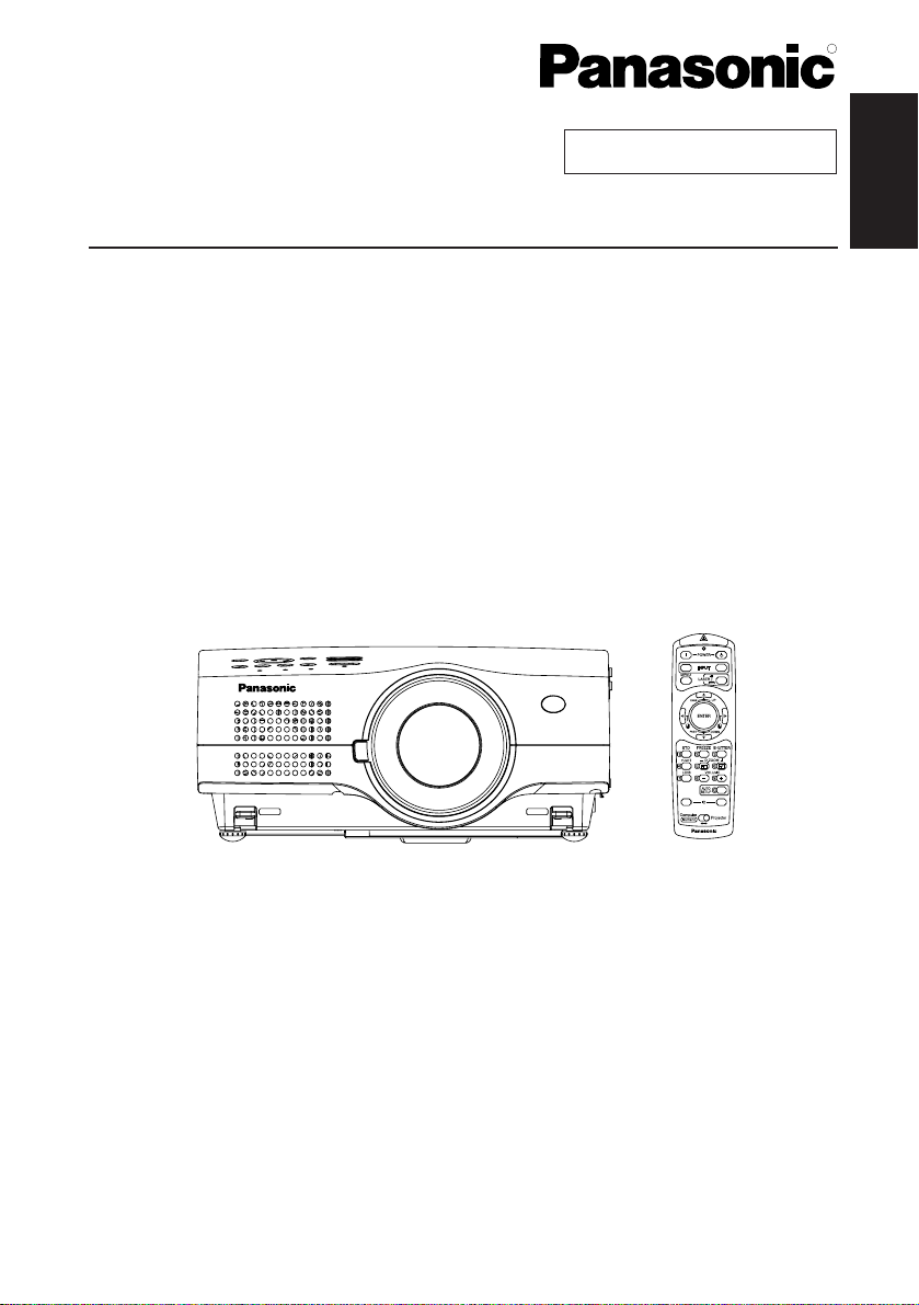
LCD Projector
Operating Instructions
Model No. PT-L785U
TQBJ 0150
Commercial Use
R
RGB
ALL SET
VIDEO
A
2-ENGLISH
IMPORTANT SAFETY NOTICE
Dear Panasonic Customer:
This instruction booklet provides all the necessary operating information that you
might require. We hope it will help you to get the most out of your new product,
and that you will be pleased with your Panasonic LCD projector.
The serial number of your product may be found on its bottom. You should note
it in the space provided below and retain this booklet in case service is required.
Model number: PT-L785U
Serial number:
WARNING:
TO REDUCE THE RISK OF FIRE OR ELECTRIC SHOCK, DO
NOT EXPOSE THIS PRODUCT TO RAIN OR MOISTURE.
The lightning flash with arrowhead symbol, within an
equilateral triangle, is intended to alert the user to the
presence of uninsulated “dangerous voltage” within the
product’s enclosure that may be of sufficient magnitude to
constitute a risk of electric shock to persons.
The exclamation point within an equilateral triangle is
intended to alert the user to the presence of important
operating and maintenance (servicing) instructions in the
literature accompanying the product.
Power Supply: This LCD Projector is designed to operate on 100 V – 240 V, 50 Hz/60
Hz AC, house current only.
CAUTION: The AC power cord which is supplied with the projector as an accessory can
only be used for power supplies up to 125 V, 7 A. If you need to use higher
voltages or currents than this, you will need to obtain a separate 250 V
power cord. If you use the accessory cord in such situations, fire may result.
CAUTION:
This equipment is equipped with a three-pin grounding-type power
plug. Do not remove the grounding pin on the power plug. This
plug will only fit a grounding-type power outlet. This is a safety
feature. If you are unable to insert the plug into the outlet, contact
an electrician. Do not defeat the purpose of the grounding plug.
Do not remove

ENGLISH-3
Preparation
WARNING:
This equipment has been tested and found to comply with the limits for a
Class B digital device, pursuant to Part 15 of the FCC Rules. These limits
are designed to provide reasonable protection against harmful interference
in a residential installation. This equipment generates, uses and can
radiate radio frequency energy and, if not installed and used in accordance
with the instructions, may cause harmful interference to radio
communications. However, there is no guarantee that interference will not
occur in a particular installation. If this equipment does cause harmful
interference to radio or television reception, which can be determined by
turning the equipment off and on, the user is encouraged to try to correct
the interference by one or more of the following measures:
– Reorient or relocate the receiving antenna.
– Increase the separation between the equipment and receiver.
– Connect the equipment into an outlet on a circuit different from that to
which the receiver is connected.
– Consult the dealer or an experienced radio/TV technician for help.
FCC CAUTION: To assure continued compliance, use only shielded
interface cables when connecting to computers or
peripheral devices.
Any unauthorized changes or modifications to this
equipment will void the users authority to operate.
WARNING:
B Not for use in a computer room as defined in the Standard for the
Protection of Electronic Computer/Data Processing Equipment,
ANSI/NFPA 75.
Declaration of Conformity
Model Number: PT-L785U
Trade Name: Panasonic
Responsible party: Matsushita Electric Corporation of America.
Address: One Panasonic Way Secaucus New Jersey 07094
Telephone number: 1-800-528-8601 or 1-800-222-0741
Email: pbtsservice@panasonic.com
This device complies with Part 15 of the FCC Rules, Operation is subject to
the following two conditions: (1) This device may not cause harmful
interference, and (2) this device must accept any interference received,
including interference that may cause undesired operation.

4-ENGLISH
Contents
Preparation
IMPORTANT SAFETY NOTICE ...2
Precautions with regard to safety
...5
Accessories .................................9
Before use ..................................10
Location and function of each part
...12
Getting started
Setting-up...................................18
Projection methods, Projector
position, Projection distances
Connections...............................20
Connecting to video equipment,
Connecting to computer
Preparation for the remote
control unit..............................22
Setting the projector ID number
for remote control unit ...........23
Basic operation
Turning on the power................24
Turning off the power................26
Useful functions
Correcting the image position
automatically...........................28
Turning off the picture and sound
momentarily ............................29
Pausing a picture.......................29
Enlarging the picture.................30
Adjusting the volume ................30
Adjusting the zoom and focus ...31
Useful functions of the remote
control unit..............................32
Laser beam pointer, Wireless mouse
Adjustments and settings
On-screen menus ......................34
Menu screens, Menu operation guide,
Returning a setting to the factory default
Adjusting the picture.................39
PICTURE MODE, CONTRAST,
BRIGHT, COLOR, TINT, SHARPNESS,
COLOR TEMP., Noise Reduction (NR),
WHITE BALANCE R/G/B, TV-SYSTEM,
Projecting sRGB-compatible pictures
Adjusting the position...............42
POSITION, DOT CLOCK, CLOCK
PHASE, KEYSTONE, OSD
POSITION, ASPECT, RESIZING,
AUTO SETUP, FRAME LOCK
Audio adjustment ......................46
VOLUME, MUTE
Changing the display language
...46
Option settings ..........................47
OSD, AUTO SEARCH, AUTO SIGNAL, RGB2
SELECT, RGB/YP
BPR, VGA60/480p, BACK
COLOR, CINEMA REALITY, FRONT/REAR,
DESK/CEILING, FAN CONTROL, LAMP
POWER, LAMP RUN TIME, FUNC 1,
CONTROL KEY, AUTO POWER OFF, SET ID
Adjusting the lens .....................50
ZOOM/FOCUS, LENS SELECT
Network setup............................50
Setting up the security function
...51
PASSWORD SETTING, CHANGE
PASSWORD, TEXT DISPLAY,
CHANGE TEXT, LOGO DISPLAY,
LOGO CLEAR, LOGO CAPTURE
Care and maintenance
When the TEMP indicator and the
LAMP indicator are illuminated
...54
Cleaning and replacing the air filter
...56
Replacing the lamp unit ............57
Before calling for service..........60
Cleaning and maintenance .......61
Others
Using the cable cover ...............62
Putting the mains lead and remote
control unit away, Covering the
connector panel
Replacing the projection lens ...64
Projection distance for each
projection lens (sold separately)
Specifications ............................68
Appendix ....................................70
List of compatible signals, Using the
REMOTE connector, Using the SERIAL
connector, Pin assignments, Projection
dimensions calculation methods
Dimensions ................................76
Trademark acknowledgements
...76
NOTES IMPORTANTES
CONCERNANT LA SECURITE..77
Précautions de sécurité
.............
78
Avant l’utilisation
.........................
82
Remplacement du bloc de lampe
...
84

ENGLISH-5
Preparation
Precautions with regard to safety
WARNING
If you notice smoke, strange smells or noise coming from the projector,
disconnect the power cord plug from the wall outlet.
B Do not continue to use the projector in such cases, otherwise fire or
electric shocks could result.
B Check that no more smoke is coming out, and then contact an Authorized
Service Center for repairs.
B Do not attempt to repair the projector yourself, as this can be dangerous.
Do not install this projector in a place which is not strong enough to
take the full weight of the projector.
B If the installation location is not strong enough, it may fall down or tip over,
and severe injury or damage could result.
Installation work (such as ceiling suspension) should only be carried
out by a qualified technician.
B If installation is not carried out correctly, there is the danger that injury or
electric shocks may occur.
If foreign objects or water get inside the projector, or if the projector is
dropped or the cabinet is broken, disconnect the power cord plug from
the wall outlet.
B Continued use of the projector in this condition may result in fire or electric
shocks.
B Contact an Authorized Service Center for repairs.
Do not overload the wall outlet.
B If the power supply is overloaded (for example, by using too many
adapters), overheating may occur and fire may result.
Do not remove the cover or modify it in any way.
B High voltages can cause fire or electric shocks.
B For any inspection, adjustment and repair work, please contact an
Authorized Service Center.
Clean the power cord plug regularly to prevent it from becoming
covered in dust.
B If dust builds up on the power cord plug, the resulting humidity can
damage the insulation, which could result in fire. Pull the power cord plug
out from the wall outlet and wipe it with a dry cloth.
B If not using the projector for an extended period of time, pull the power
cord plug out from the wall outlet.

6-ENGLISH
Do not do anything that might damage the power cord or the power cord
plug.
B Do not damage the power cord, make any modifications to it, place it near
any hot objects, bend it excessively, twist it, pull it, place heavy objects on
top of it or wrap it into a bundle.
B If the power cord lead is used while damaged, electric shocks, short-
circuits or fire may result.
B Ask an Authorized Service Center to carry out any repairs to the power
cord that might be necessary.
Do not handle the power cord plug with wet hands.
B Failure to observe this may result in electric shocks.
Insert the power cord plug securely into the wall outlet.
B If the plug is not inserted correctly, electric shocks or overheating could
result.
B Do not use plugs which are damaged or wall outlets which are coming
loose from the wall.
Do not place the projector on top of surfaces which are unstable.
B If the projector is placed on top of a surface which is sloped or unstable, it
may fall down or tip over, and injury or damage could result.
Do not place the projector into water or let it become wet.
B Failure to observe this may result in fire or electric shocks.
Do not place liquid containers on top of the projector.
B If water spills onto the projector or gets inside it, fire or electric shocks
could result.
B
If any water gets inside the projector, contact an Authorized Service Center
.
Do not insert any foreign objects into the projector.
B Do not insert any metal objects or flammable objects into the projector or
drop them onto the projector, as doing so can result in fire or electric
shocks.
Keep the batteries out of the reach of infants.
B If the batteries are swallowed, death by suffocation may result. If you
believe that the batteries may have been swallowed, seek medical advice
immediately.
Do not allow the + and - terminals of the batteries to come into contact
with metallic objects such as necklaces or hairpins.
B Failure to observe this may cause the batteries to leak, overheat, explode
or catch fire.
B Store the batteries in a plastic bag and keep them away from metallic
objects.
During a thunderstorm, do not touch the projector or the cable.
B Electric shocks can result.
Do not use the projector in a bath or shower.
B Fire or electric shocks can result.

ENGLISH-7
Preparation
Do not look into the lens while the projector is being used.
B Strong light is emitted from the projector’s lens. If you look directly into this
light, it can hurt and damage your eyes.
B Be especially careful not to let young children look into the lens. In
addition, turn off the power and disconnect the power cord plug when you
are away from the projector.
Keep the remote control unit out of the reach of children, and do not
look into the laser beam or point it towards other people.
B If the laser beam which is emitted by the remote control unit transmitter is
pointed directly into the eyes, it may cause visual ability to be impaired.
Do not place your hands or other objects close to the air outlet port.
B Heated air comes out of the air outlet port. Do not place your hands or
face, or objects which cannot withstand heat close to this port, otherwise
burns or damage could result.
Replacement of the lamp unit should only be carried out by a qualified
technician.
B The lamp unit has high internal pressure. If improperly handled, explosion
might result.
B The lamp unit can easily become damaged if struck against hard objects
or dropped, and injury or malfunctions may result.
When replacing the lamp, allow it to cool for at least one hour before
handling it.
B The lamp cover gets very hot, and contact with it can cause burns.
Before replacing the lamp, be sure to disconnect the power cord plug
from the wall outlet.
B Electric shocks or explosions can result if this is not done.
Caution
Do not cover the air inlet port or the air outlet port.
B Doing so may cause the projector to overheat, which can cause fire or
damage to the projector.
B Do not place the projector in narrow, badly ventilated places such as
closets or bookshelves.
Do not set up the projector in humid or dusty places or in places where
the projector may come into contact with smoke or steam.
B Using the projector under such conditions may result in fire or electric shocks.
When disconnecting the power cord, hold the plug, not the lead.
B If the power cord itself is pulled, the lead will become damaged, and fire,
short-circuits or serious electric shocks may result.
Always disconnect all cables before moving the projector.
B Moving the projector with cables still attached can damage the cables,
which could cause fire or electric shocks to occur.

8-ENGLISH
Do not place any heavy objects on top of the projector.
B Failure to observe this may cause the projector to become unbalanced
and fall, which could result in damage or injury.
Do not short-circuit, heat or disassemble the batteries or place them
into water or fire.
B Failure to observe this may cause the batteries to overheat, leak, explode
or catch fire, and burns or other injury may result.
When inserting the batteries, make sure the polarities (+ and -) are
correct.
B If the batteries are inserted incorrectly, they may explode or leak, and fire,
injury or contamination of the battery compartment and surrounding area
may result.
Use only the specified batteries.
B If incorrect batteries are used, they may explode or leak, and fire, injury or
contamination of the battery compartment and surrounding area may
result.
Do not mix old and new batteries.
B If the batteries are inserted incorrectly, they may explode or leak, and fire,
injury or contamination of the battery compartment and surrounding area
may result.
Insulate the battery using tape or similar before disposal.
B If the battery comes into contact with metallic objects or other batteries, it
may catch fire or explode.
Do not put your weight on this projector.
B You could fall or the projector could break, and injury may result.
B Be especially careful not to let young children stand or sit on the projector.
Do not lift up the projector by holding the cable cover.
B Failure to observe this may cause the cable cover to come off and the
projector might fall, which could result in injury.
Disconnect the power cord plug from the wall outlet as a safety
precaution before carrying out any cleaning.
B Electric shocks can result if this is not done.
Ask an Authorized Service Center to clean inside the projector at least
once a year.
B If dust is left to build up inside the projector without being cleaned out, it
can result in fire or problems with operation.
B It is a good idea to clean the inside of the projector before the season for
humid weather arrives. Ask your nearest Authorized Service Center to
clean the projector when required. Please discuss with the Authorized
Service Center regarding cleaning costs.
We are constantly making efforts to preserve and maintain a clean
environment. Please take non repairable units back to your dealer or a
recycling company.
ENGLISH-9
Preparation
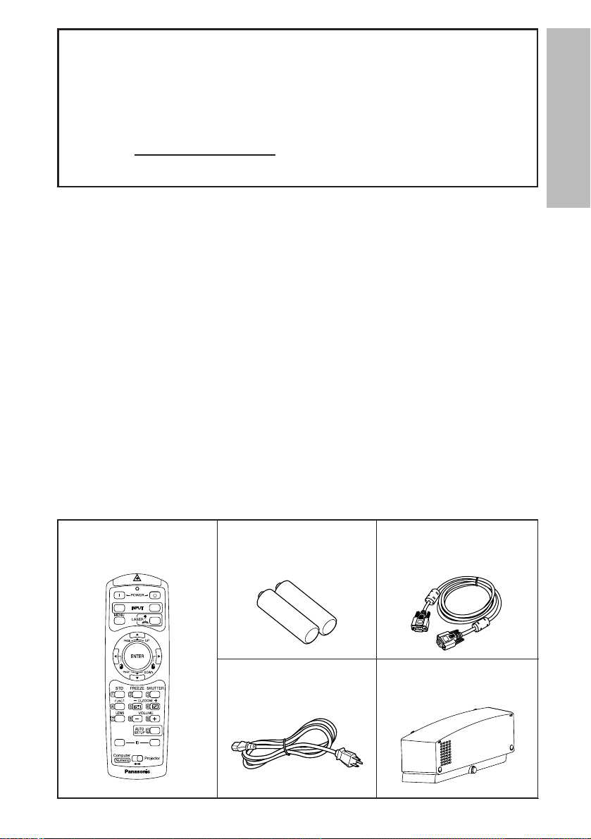
Remote control unit
(N2QAEA000022 x1)
AAA batteries for
remote control unit (x2)
RGB signal cable
[3.0 m (9´10˝),
K1HB15FA0001 x1]
Accessories
Check that all of the accessories shown below have been included with your
projector.
VIDEO
RGB
ALL SET
A
Power cord
(K2CG3FZ00008 x 1)
Cable cover
(TXFKR01VJX7 x1)
NOTICE:
B This product has a High Intensity Discharge (HID) lamp that contains a
small amount of mercury. It also contains lead in some components.
Disposal of these materials may be regulated in your community due to
environmental considerations. For disposal or recycling information
please contact your local authorities, or the Electronics Industries
Alliance: <http://www.eiae.org.>

10-ENGLISH
Before use
Caution when moving the projector
Be sure to attach the lens cover before moving the projector.
The projection lens is extremely susceptible to vibration and shocks. Be
careful not to subject it to excessive vibration and shock when moving the
projector.
Cautions regarding setting-up
Avoid setting up in places which are subject to vibration or shocks.
The internal parts can be damaged, which may cause malfunctions or
accidents.
Do not set up the projector near high-voltage power lines or near
motors.
The projector may be subject to electromagnetic interference.
If installing the projector to the ceiling, ask a qualified technician to
carry out all installation work.
You will need to purchase the separate installation kit (Model No.ET-PK780).
Furthermore, all installation work should only be carried out by a qualified
technician.
If using this projector at high elevations (above 1 400 m), set the “FAN
CONTROL” to “HIGH”. (Refer to page 48.)
Failure to observe this may result in malfunctions.

ENGLISH-11
Preparation
Notes on use
In order to get the best picture quality
Draw curtains or blinds over any windows and turn off any lights near the
screen to prevent outside light or light from indoor lamps from shining onto
the screen.
Do not touch the surfaces of the lens with your bare hands.
If the surface of the lens becomes dirty from fingerprints or anything else, this
will be magnified and projected onto the screen. Moreover, when not using
the projector, retract the lens and then cover it with the lens cover.
Screen
Do not apply any volatile substances which may cause discoloration to the
screen, and do not let it become dirty or damaged.
Lamp
The lamp may need to be replaced earlier due to variables such as individual
lamp characteristics, usage conditions and the installation environment,
especially when the projector is subjected to continuous use for more than
10 hours or the power is frequently turned on and off, as the operations that
prevent blackening of the bulb (the action of the halogen cycle) do not work
enough during short periods of time.
Liquid crystal panel
The liquid crystal panel of the projector is built with very high precision
technology to provide fine picture details. Occasionally, a few non-active
pixels may appear on the screen as fixed points of blue, green or red.
Please note that this does not affect the performance of your LCD.

12-ENGLISH
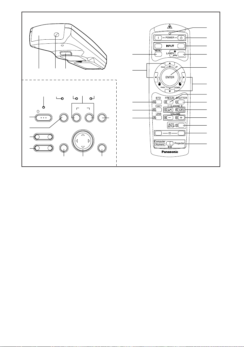
Location and function of each part
Projector <Top, right and front>
#$
&
(+
+
**)
%
'
0
,-.
/
(
# Projector control panel (page 14)
$ Speaker
% Connector panel (page 16)
& MAIN POWER switch (pages 24 and 26)
' Power input socket (AC IN) (page 24)
The accessory power cord is connected here.
Do not use any power cord other than the accessory power cord.
( Air inlet ports
Do not cover these ports.
) Air filter (page 56)
* Front adjustable legs(L/R) (page 25)
+ Leg adjuster buttons(L/R) (page 25)
These buttons are used to unlock the front adjustable legs. Press to adjust
the angle of tilt of the projector.
, Remote control signal receptor (page 22)
- Focus ring (page 25)
. Lens cover
/ Projection lens
0 Lens release button (page 64)
This button is used when using a projection lens that is sold separately.
ENGLISH-13
Preparation
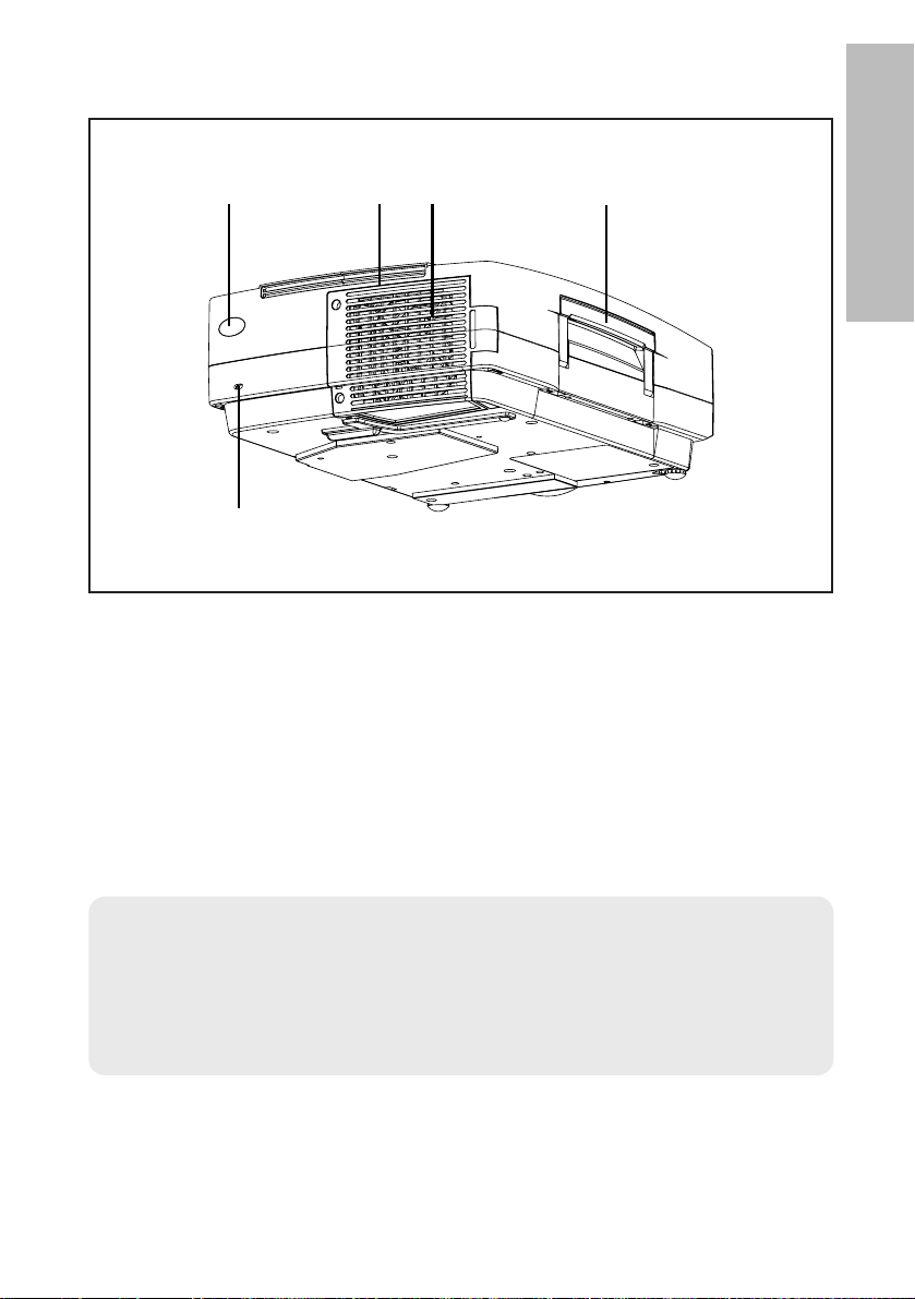
# Remote control signal receptor (page 22)
$ Lamp unit holder (page 57)
% Air outlet port
Do not cover this port.
& Carrying handle
' Security lock
This can be used to connect a commercially-available theft-prevention
cable (manufactured by Kensington). This security lock is compatible with
the Microsaver Security System from Kensington.
WARNING
Do not place your hands or other objects close to the air outlet port.
B Heated air comes out of the air outlet port. Do not place your hands or
face, or objects which cannot withstand heat close to this port, otherwise
burns or damage could result.
Projector <Back and bottom>
NOTE:
B During projection of an image, the cooling fan will operate, emitting a
small noise as it operates. Turning the lamp on or off will cause this
noise to increase a little.
B By using the “OPTION” menu to set “LAMP POWER” to “LOW”, the
operating sound of the fan can be reduced. (Refer to page 48.)
#$%'&
14-ENGLISH
Remote control unit
# Power indicator (pages 24, 26 and 27)
This indicator illuminates red when the MAIN POWER switch is turned on,
and illuminates green when the power is turned on and a picture starts to
be projected.
When the projector is in “WEB STANDBY” mode, this indicator flashes slowly
in red.
$ RGB INPUT indicator (page 27)
This indicator illuminates when a signal is input into the connector that is
selected with the input select buttons.
% LAMP indicator (page 55)
This indicator illuminates when it is time to replace the lamp unit. It flashes
if a circuit abnormality is detected.
& INPUT (RGB, VIDEO) buttons (page 25)
These buttons are used to select the input signals. When “AUTO SEARCH” in the
“OPTION” menu is set to “ON”, the input signal will be detected and selected
automatically by pressing this button for a few seconds. (Refer to page 47.)
' TEMP indicator (page 54)
This indicator illuminates if an abnormally high temperature is detected inside
the projector or around it. If the temperature rises above a certain level, the
power supply will be turned off automatically and the indicator will flash.
( SHUTTER button (page 29)
This button is used to momentarily turn off the picture and sound.
) ENTER button (page 38)
This button is used to accept and to activate items selected in the onscreen menus.
Projector control panel
+
RGB
VIDEO
6
/
&
7
0
12
*
'
&
#
POWER
/
STANDBY(R)
ON(G)
.
– FOCUS +
-
–
ZOOM +
,
%
$
LAMPRGB INPUT
INPUT
MENU
+*
TEMP
RGBVIDEOAUTO SETUP
SHUTTER
ENTER
)
(
3
4
5
A
ALL SET
)
*
8
(
9
:
.
;
<

ENGLISH-15
Preparation
*When in computer operating mode, this button on the remote control unit
functions differently. (page 33)
* Arrow (
FFGGII
and HH) buttons (page 37)
These buttons are used to select and adjust items in the on-screen menus.
*When in computer operating mode, these buttons on the remote control
unit function differently. (page 33)
+ MENU button (pages 34 and 37)
This button is used to display the menu screens. When a menu screen is
being displayed, this button can be used to return to a previous screen or
to clear the screen.
, ZOOM +/- buttons (page 25)
These buttons are used to adjust the size of the projected image.
- FOCUS +/- buttons (page 25)
These buttons are used to adjust the focus of the projected image.
. AUTO SETUP button (pages 25 and 28)
If this button is pressed while a picture is being projected, the projection settings
will be adjusted automatically in accordance with the signal being input.
/ POWER button (pages 24 and 26)
These buttons are used to turn the power on and off when MAIN POWER
is turned on.
(For the remote control unit, the “ ” button is for turning on the power and
the “ ” button is for turning off the power.)
0 Laser emitter (page 32)
1 Infrared emitter (page 22)
2 Click button (page 33)
This button can be used when the operating mode select switch is moved
to the left (Computer).
3 STD (standard) button (page 38)
This button is used to reset the projector adjustment values to the factory
default settings.
4 FUNC1 button (pages 43, 46 and 49)
This button can be used for 1) switching on and off the sound volume and
2) entering into the keystone distortion correction mode. Adjust “FUNC1”
in the “OPTION” menu to select which you wish to use.
5 LENS button (page 31)
This button is used to display the zoom and focus adjustment screen.
6 Operation indicator (page 32)
This indicator illuminates while a laser beam is being emitted (while the LASER
button is being pressed). It flashes when any other buttons are being pressed.
7 LASER button (page 32)
A beam of laser light is emitted while this button is being pressed. This
laser beam can be used as a pointer to point to something on the screen.
8 FREEZE button (page 29)
This button is used to momentarily freeze projection so that a still picture is displayed.
9 D.ZOOM +/- buttons (page 30)
These buttons are used to enlarge the projected image.
(continued on next page)
16-ENGLISH
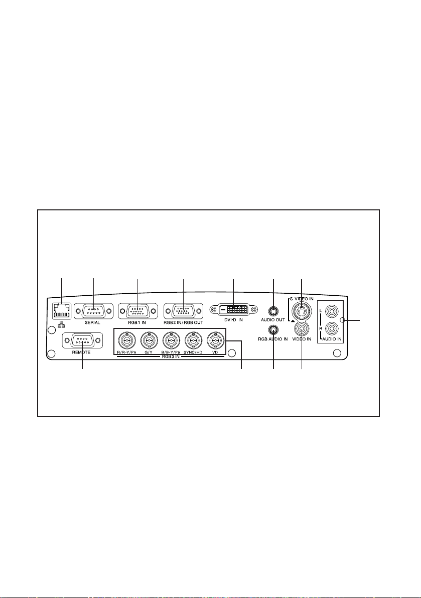
Connector panel
# Wired LAN connector
This connector is used to connect a personal computer to the projector in
order to externally control the projector. (10 Base-T/100 Base-TX)
Refer to the “Network Function Edition” operating instructions for details.
$ SERIAL connector (pages 20, 21 and 72)
This connector is used to connect a personal computer to the projector in
order to externally control the projector. (RS-232C compatible)
% RGB1 IN connector (pages 20 and 21)
This connector is used to input RGB signals and YPBPR signals.
: VOLUME +/- buttons (page 30)
These buttons are used to adjust the volume of the sound that is output
from the projector’s built-in speakers and AUDIO OUT connector. Refer to
page 46 for details on how to adjust the volume using the buttons on the
projector control panel.
; ID SET/ALL button (page 23)
These buttons are used to set the projector ID number into the remote
control unit when using multiple projectors with a single remote control
unit.
< Operating mode (Computer, Projector) select switch (page 33)
Move this switch to the left side to use the remote control unit to operate a
computer, and move it to the right side to operate the projector.
(continued from previous page)
$#
& ( )%
'
, - .+
*

ENGLISH-17
Preparation
& RGB2 IN/RGB OUT connector (pages 20, 21 and 47)
This connector is used to input or output RGB signals and YPBPR signals.
Adjust “RGB2 SELECT” in the “OPTION” menu to select whether you want
input or output with this connector.
' DVI-D IN connector (page 21)
This connector is used to input DVI-D signals.
( AUDIO OUT connector (pages 20 and 21)
This connector is used to output the audio signals which are input to the
projector. If audio equipment is connected to this connector, no sound will
be output from the built-in speakers.
) S-VIDEO IN connector (pages 20 and 45)
This connector is used to input signals from a S-VIDEO-compatible
equipment such as a video deck. The connector is S1 signal compatible,
and it automatically switches between 16:9 and 4:3 aspect ratios in
accordance with the type of signal being input.
* AUDIO IN L-R connectors (for S-VIDEO/VIDEO) (page 20)
Only one system is provided, so connect the appropriate connectors when
using S-VIDEO or VIDEO.
+ REMOTE connector (page 71)
This connector is used to control the projector from the remote control set
up in wired mode.
, RGB3 IN connector (pages 20 and 21)
This connector is used to input RGB signals and YPBPR signals.
- RGB AUDIO IN connector (pages 20 and 21)
Only one system is provided, so connect the appropriate connector when
using RGB1, RGB2 or RGB3.
. VIDEO IN connector (page 20)
This connector is used to input video signals from a video equipment such
as a video deck.
18-ENGLISH
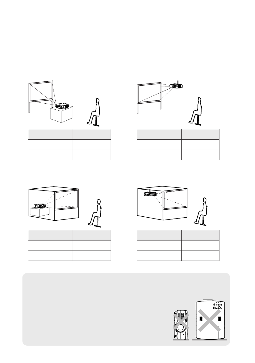
Setting-up
Projection methods
In way of installing projector, any one of the following four projection methods
are used. Select whichever projection method matches the setting-up
method. (The projection method can be set from the “OPTION” menu. Refer
to page 48 for details.)
BFront-desk projection BFront-ceiling projection
BRear-desk projection
(Using a translucent screen)
BRear-ceiling projection
(Using a translucent screen)
Menu items Setting
FRONT
DESK
FRONT/REAR
DESK/CEILING
Menu items Setting
FRONT
CEILING
FRONT/REAR
DESK/CEILING
Menu items Setting
REAR
DESK
FRONT/REAR
DESK/CEILING
Menu items Setting
REAR
CEILING
FRONT/REAR
DESK/CEILING
NOTE:
B You will need to purchase the separate ceiling bracket (ET-PK780)
when using the ceiling installation method.
B If you set up the projector vertically, it may cause
damage to the projector.
B It is recommended that you set up the projector
in a place that is tilted at less than
±30°. Setting
up the projector in places that are tilted at more
than
±30° may cause malfunctions.
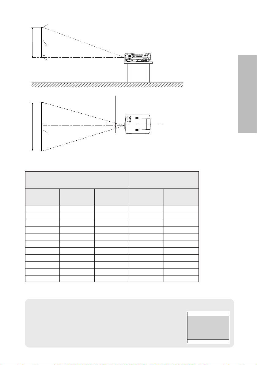
ENGLISH-19
Getting started
L
L
SH
SW
25 mm
(-31/32˝)
L: Projection distance
SH: Image height
SW:Image width
Top edge of screen
Screen
Bottom edge of screen
Screen
NOTE:
B The dimensions in the table above are approximate.
B If you use the projection distance for the 16:9 screen,
the 4:3 projection image overflows the screen at the top
and bottom.
B
For details about projected image distances, refer to page 75.
Projector position
1.01 m(40˝) 0.61 m(2´) 0.81 m(2´8˝) 1.6 m(5´2˝) 2.0 m(6´6˝)
1.27 m(50˝) 0.76 m(2´6˝) 1.02 m(3´4˝) 2.0 m(6´6˝) 2.6 m(8´6˝)
1.52 m(60˝) 0.91 m(3´) 1.22 m(4´) 2.4 m(7´10˝) 3.1 m(10´2˝)
1.77 m(70˝) 1.07 m(3´6˝) 1.42 m(4´8˝) 2.8 m(9´2˝) 3.6 m(11´9˝)
2.03 m(80˝) 1.22 m(4´) 1.63 m(5´4˝) 3.2 m(10´5˝) 4.2 m(13´9˝)
2.28 m(90˝) 1.37 m(4´6˝) 1.83 m(6´) 3.6 m(11´9˝) 4.7 m(15´5˝)
2.54 m(100˝) 1.52 m(5´) 2.03 m(6´8˝) 4.0 m(13´1˝) 5.3 m(17´4˝)
3.81 m(150˝) 2.29 m(7´6˝) 3.05 m(10´) 6.1 m(20´) 7.9 m(25´11˝)
5.08 m(200˝) 3.05 m(10´) 4.06 m(13´4˝) 8.1 m(26´6˝) 10.6 m(34´9˝)
6.35 m(250˝) 3.81 m(12´6˝) 5.08 m(16´8˝) 10.1 m(33´1˝) 13.3 m(43´7˝)
7.62 m(300˝) 4.57 m(15´) 6.10 m(20´) 16.0 m(52´5˝)
Projection distances*
Screen size (4:3)
Diagonal
length
Height
(SH)
Width
(SW)
Projection distance (L)
Wide
(LW)
Telephoto
(LT)
12.2 m(40´)
*For standard lens which is supplied with the projector. Refer to pages 65 –
67 for details on the projection distances for the optional lenses.
20-ENGLISH
Connections
Notes on connections
B
Read the instruction manual for each peripheral device carefully before connecting it.
B
Turn off the power supply for all peripheral devices before making any connections.
B
If the cables necessary for connection are not included with the peripheral device or
available as an option, you may need to prepare a proper cable for the device concerned.
B
If there is a lot of jitter in the video signal, the projected image may flicker. In such
cases, it will be necessary to connect a TBC (time base corrector).
B
Refer to the list on page 70 for details on compatible signals which can be input to
the projector.
B
Only one audio system circuit is available for each of the AUDIO IN L-R connectors for
S-VIDEO/VIDEO signals and the RGB AUDIO IN connector, so if you wish to change
the audio input source, you will need to remove and insert the appropriate plugs.
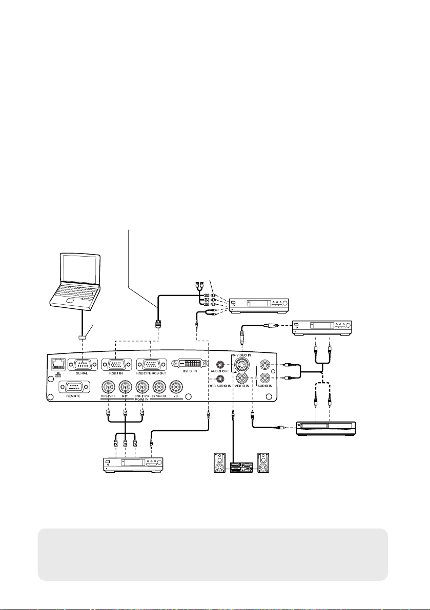
Connecting to video equipment
D-sub 15-pin (male) - BNCx5 (male) adapter cable
Red (connect to PR signal connector)
Blue (connect to PB signal connector)
Green (connect to Y signal connector)
D-sub 9-pin
(male)
DVD player Audio system
Video deck
Computer for
control use
DVD player
Red (connect to PR signal connector)
Blue (connect to PB signal connector)
Green (connect to Y signal connector)
DVD player
(with component
video connectors)
BNC/RCA adapter
NOTE:
B If the signal cables are disconnected or if the power supply for the
computer or video deck is turned off while “D.ZOOM”(digital zoom) is
being used, this function will be cancelled.
ENGLISH-21
Getting started
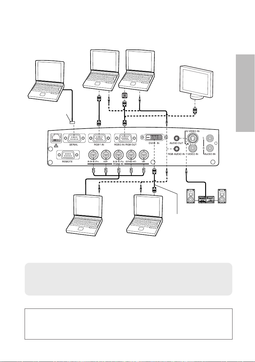
Connecting to computer
1 623 4 5
ON DIP
D-sub 9-pin
(male)
Computer for
control use
Computer
Monitor
Audio system
Computer
Computer (with
DVI-D OUT connector)
DVI cable
(ET-SCDV03: sold
separately)
NOTE:
B Do not input the signal to the RGB2 IN/RGB OUT connector when
“RGB2 SELECT” in the “OPTION” menu is set to “OUTPUT”. (Refer to
page 47.)
Refer to the “Network Function Edition” operating instructions for
details on connecting the projector to a personal
computer using the wired LAN connector.
22-ENGLISH
Preparation for the remote control unit
NOTE:
B Do not drop the remote control unit.
B Keep the remote control unit away from liquids.
B Remove the batteries if not using the remote control unit for long periods.
B Do not use rechargeable batteries.
B If the remote control unit is held so that it is facing directly in front of the
remote control signal receptors on the front or rear of the projector, the
operating range is within approximately 7 m (23´) from the surfaces of
the receptors. Furthermore, the remote control unit can be operated
from an angle of ±30° to the left or right and ±15° above or below the
receptors.
B If there are any obstacles in between the remote control unit and the
receptors, the remote control unit may not operate correctly.
B If strong light is allowed to shine onto the remote control signal receptor,
correct projector operation may not be possible. Place the projector as
far away from light sources as possible.
B
If facing the remote control unit toward the screen to operate the projector,
the operating range of the remote control unit will be limited by the amount
of light reflection loss caused by the characteristics of the screen used.
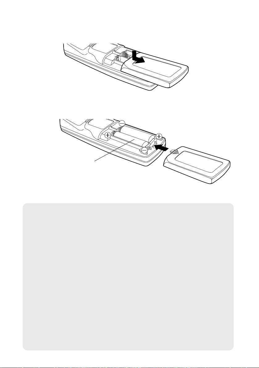
# Open the cover.
AAA batteries
(two)
$ Insert the batteries so that the polarities
are correct, and then close the cover.
NOTE:
B If the entered ID number is more than 64, the ID number will return to
the one set before the ID SET button was pressed.
B The ID number setting screen will be canceled if no number is entered
for 5 seconds or if any button except the numeric buttons is pressed.
B If the ID SET button is pressed after a number less than 10 is entered,
the entered number will be cancelled.
B If ID number is set to “ALL” by pressing the ID ALL button, the
projectors can be controlled regardless of their ID number setting.
B The projector cannot be turned on and off from the remote control unit if
the “CONTROLLER ID” does not match the projector ID number. For
more details on projector ID number setting, see page 49.
B The projector ID number in the remote control unit is set to “ALL” by
default. It is therefore not necessary to set a projector ID number when
only one projector is used.
ENGLISH-23
Getting started
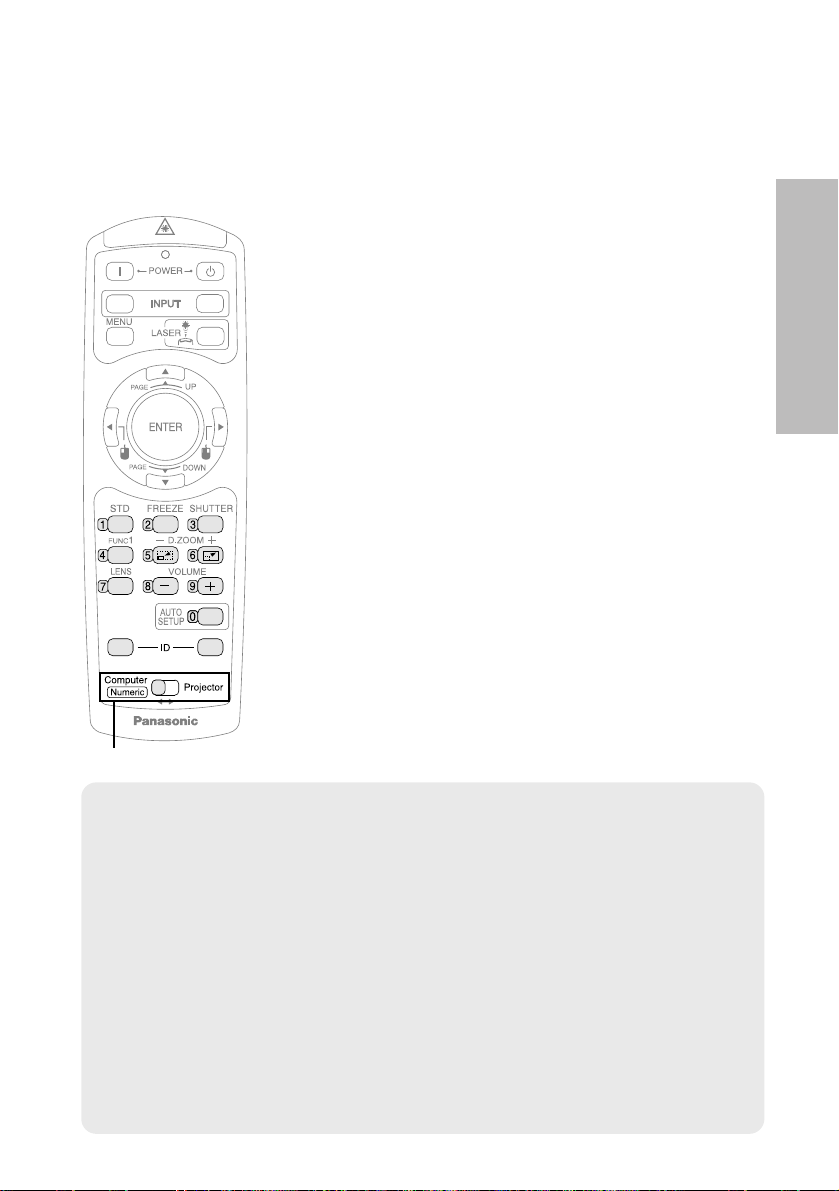
Setting the projector ID number for
the remote control unit
When controlling multiple projectors individually or simultaneously with a
single remote control unit, a projector ID number must be set into the remote
control unit as described in the following steps.
# When setting the projector ID number, move
the mode switch to the left side (Numeric).
$ Press the ID SET button on the remote
control unit.
The projector ID number which is currently set
will be displayed on the screen.
% Press the numeric (0 - 9) buttons on the
remote control unit to set the ID number.
The entered ID number will be displayed on the
screen. (You can set from the number 1 to the
number 64.)
B
If the entered ID number is 10 - 64, the ID number
setting will be completed.
B If the ID number entered is less than 10, press
any button other than the numeric buttons or the
ID SET/ALL button, or wait for about 5 seconds
to complete the setting.
VIDEO
RGB
ALL SET
A
Mode switch
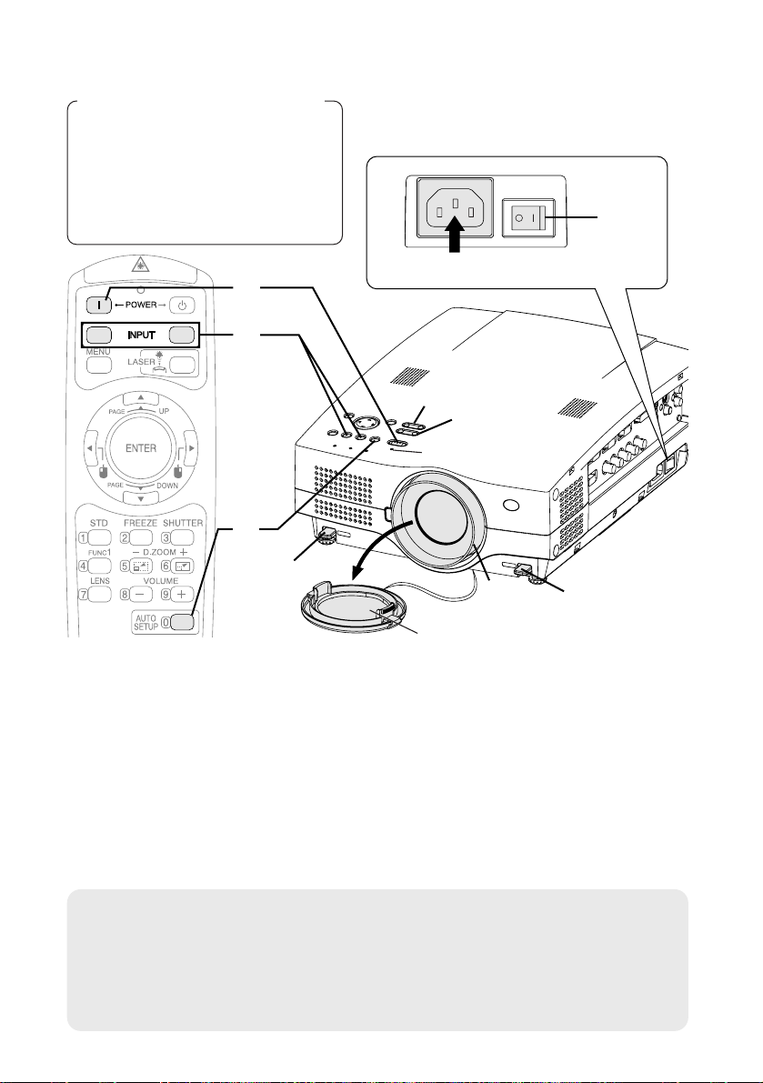
Turning on the power
Before turning on the power
1, Ensure that all peripheral
devices are connected
properly.
2, Connect the accessory power
cord.
3, Remove the lens cover.
Lens cover
Press the MAIN POWER switch to turn on the power.
BThe power indicator on the projector will illuminate red.
Press the POWER button.
BThe power indicator on the projector will flash green. After a short
period, the indicator will illuminate green, and a picture will be
projected.
Turn on the power of all connected devices.
BStart the play function of a device such as a DVD player.
NOTE:
B A tinkling sound may be heard when the lamp unit is turned on, but this
is not a sign of a malfunction.
B The projector cannot be turned on and off from the remote control unit
if the “CONTROLLER ID” does not match the projector ID number.
(pages 23 and 49)
#
$
%
24-ENGLISH
$
&
(
'
*
*
)
'
#
Power indicator
Power cord
RGB
VIDEO
A
ENGLISH-25
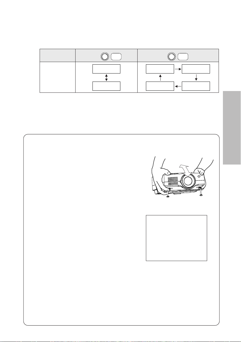
Basic Operation
Press the input select button to select the
input signal.
Follow the procedure below when you set the projector up first, and when
you change the setup place.
Press the AUTO SETUP button to initiate
automatic positioning.
BThe position of the projected image
will be corrected automatically in
accordance with the input signal.
(Refer to page 28 for details.)
B
If the projected image contains
keystone distortion, adjust
“KEYSTONE” in the “POSITION” menu (refer to page 43 for details).
Input select
buttons
Changing
signals
VIDEO
VIDEO
RGB
RGB
VIDEO
S-VIDEO
RGB1
RGB3DVI
RGB2
&
'
Adjusting the angle
BWhile pressing the adjuster buttons,
adjust the forward/back angle of tilt
of the projector. Adjust so that the
projector is as vertical to the screen
as possible.
BA picture will be projected in accordance with the selected input
signal.
BWhen an YPBPR signal is being input, “YPBPR” will be displayed
(when “RGB/YPBPR” in the “OPTION” menu is set to “YPBPR”.
Refer to page 47 for details).
Adjusting the focus
B
Press the FOCUS +/- buttons to adjust the focus of the projected image.
The focus of the projected image can also be adjusted by turning the
focus ring. To make fine adjustments, use the FOCUS +/- buttons.
Adjusting the size
BPress the ZOOM +/- buttons to adjust the size of the projected image.
)
*
(
AUTO SETUP
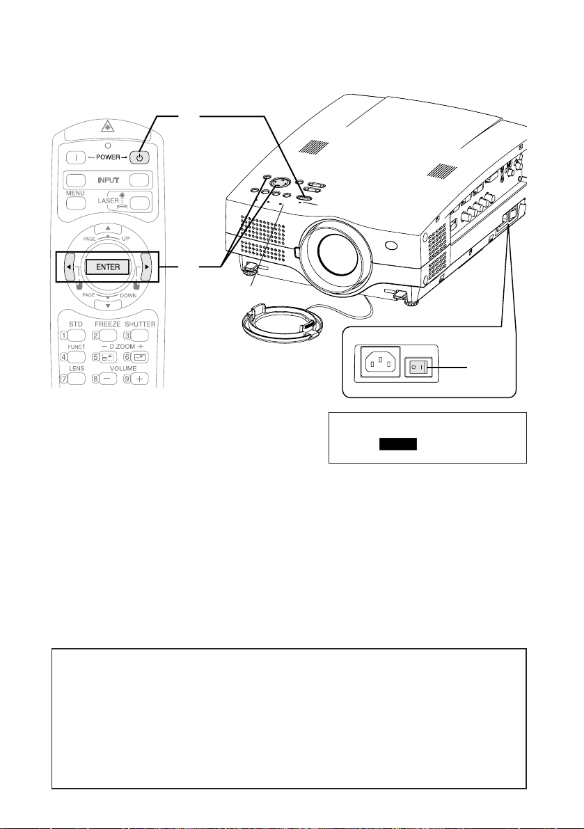
Turning off the power
Press the POWER button.
B“Power OFF” is displayed on the
screen.
Press the IIor HHbutton to select “OK”, and
then press the ENTER button.
BThe lamp unit will switch off and the picture will stop being projected.
(The power indicator on the projector will illuminate orange while the
cooling fan is still operating.)
#
$
26-ENGLISH
VIDEO
RGB
#
$
%
Power indicator
RGB INPUT indicator
Power OFF
OK CANCEL
%
Press the MAIN POWER switch to turn off the
power after the power indicator on the
projector illuminates red.
Direct power off function
You can turn off the MAIN POWER switch and move the projector
immediately after use. The cooling fan will operate by the internal power
supply to cool down the lamp.
B When this function is used, it may take more time for the lamp to turn
back on again compared to when the lamp cools down while the MAIN
POWER switch is ON.
B Do not put the projector in a bag while the cooling fan is operating.
ENGLISH-27
Basic Operation
NOTE:
B You can also turn off the power by pressing the POWER button twice or
by holding it down for at least 0.5 seconds.
B When the projector is in standby mode (the power indicator on the
projector is illuminated red), the projector continues to draw approximately
11 W of power even when the cooling fan has stopped.
B
When the projector is in “WEB STANDBY” mode, the cooling fan operates
and the power indicator on the projector flashes slowly in red and the
projector continues to draw approximately 40 W of power. (page 50)
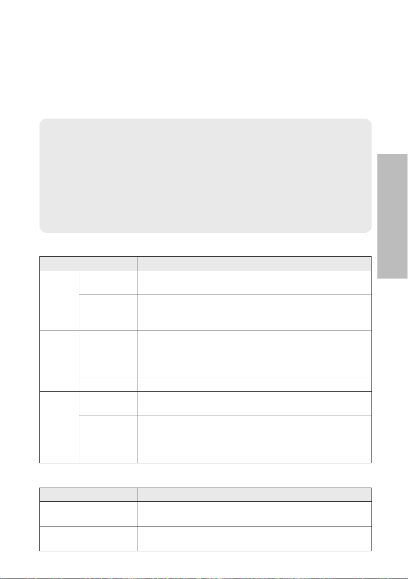
Power indicator
Power indicator status
Red
Illuminated
The projector is in standby mode and image projection
is possible by pressing the POWER button.
A picture is being projected.
The lamp is cooling down after the power is turned
off. (The cooling fan is operating.)
The projector is preparing for projection after the
power is turned on while the power indicator is
illuminated orange. (After a short period, a picture
will be projected.)
The projector is preparing for projection after the
power is turned on while the power indicator is
illuminated red. (After a short period, a picture will be
projected.)
Flashing
The projector is in “WEB STANDBY” mode, and can be
controlled with personal computers via a wired LAN.
(The cooling fan is operating.)
Flashing
slowly
Illuminated
Illuminated
Flashing
Green
Orange
Projector status
RGB INPUT indicator
RGB INPUT indicator status
Illuminated during
standby mode
A signal is being input to one of the RGB1 IN, RGB2
IN or RGB3 IN connectors.
Illuminated during
projection
A signal is being input to the connector selected
using the input select buttons.
Projector status