

Panasonic PT-L780 User Manual
R
Before operating this product, please read the instructions carefully and save this
manual for future use.
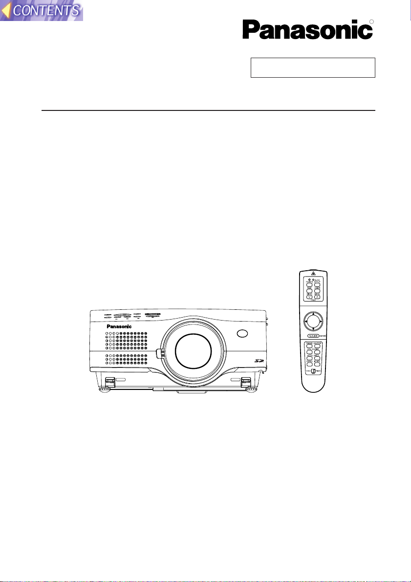
LCD Projector
Operating Instructions
Model No. PT-L780NTU
PT-L750U
R
TQBH9003-6
Commercial Use
2
IMPORTANT SAFETY NOTICE
WARNING:
TO REDUCE THE RISK OF FIRE OR ELECTRIC SHOCK, DO
NOT EXPOSE THIS PRODUCT TO RAIN OR MOISTURE.
Dear Panasonic Customer:
This instruction booklet provides all the necessary operating information that
you might require. We hope it will help you to get the most performance out
of your new product, and that you will be pleased with your Panasonic LCD
projector.
The serial number of your product may be found on its back. You should
note it in the space provided below and retain this booklet in case service is
required.
Model number: PT-L780NTU / PT-L750U
Serial number:
The lightning flash with arrowhead symbol, within an
equilateral triangle, is intended to alert the user to the
presence of uninsulated “dangerous voltage” within the
product’s enclosure that may be of sufficient magnitude to
constitute a risk of electric shock to persons.
The exclamation point within an equilateral triangle is
intended to alert the user to the presence of important
operating and maintenance (servicing) instructions in the
literature accompanying the product.
Power Supply: This LCD Projector is designed to operate on 100 V – 240 V, 50 Hz/60
Hz AC, house current only.
CAUTION: The AC power cord which is supplied with the projector as an accessory can
only be used for power supplies up to 125 V, 10 A. If you need to use higher
voltages or currents than this, you will need to obtain a separate 250 V
power cord. If you use the accessory cord in such situations, fire may result.
3
Preparation
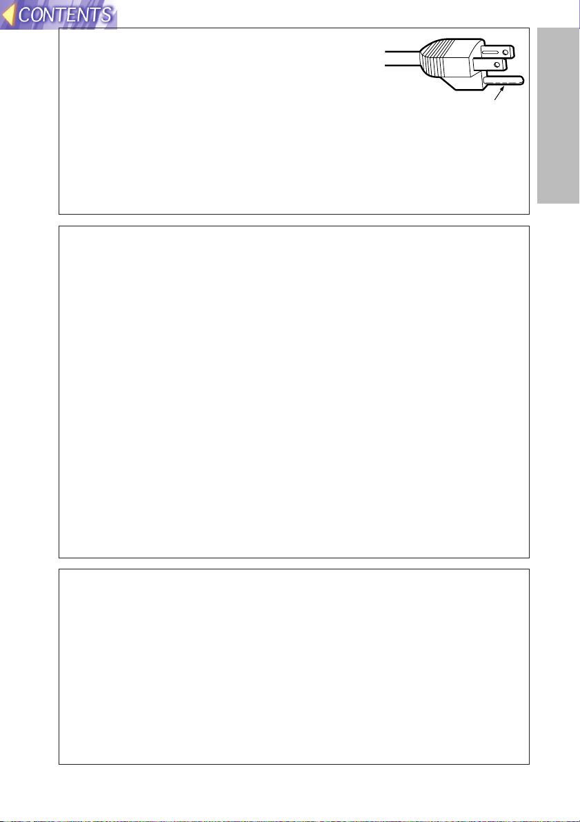
CAUTION: This equipment is equipped with a
three-pin grounding-type power
plug. Do not remove the grounding
pin on the power plug. This plug will
only fit a grounding-type power
outlet. This is a safety feature. If you
are unable to insert the plug into the
outlet, contact an electrician. Do not
defeat the purpose of the grounding
plug.
WARNING:
This equipment has been tested and found to comply with the limits for a
Class B digital device, pursuant to Part 15 of the FCC Rules. These limits
are designed to provide reasonable protection against harmful interference
in a residential installation. This equipment generates, uses, and can
radiate radio frequency energy and, if not installed and used in accordance
with the instructions, may cause harmful interference to radio
communications. However, there is no guarantee that interference will not
occur in a particular installation. If this equipment does cause harmful
interference to radio or television reception, which can be determined by
turning the equipment off and on, the user is encouraged to try to correct
the interference by one or more of the following measures:
– Reorient or relocate the receiving antenna.
– Increase the separation between the equipment and receiver.
– Connect the equipment into an outlet on a circuit different from that to
which the receiver is connected.
– Consult the dealer or an experienced radio/TV technician for help.
CAUTION: Any unauthorised changes or modifications to this equipment
will void the users authority to operate.
Do not remove
Declaration of Conformity
Model Number: PT-L780NTU / PT-L750U
Trade Name: Panasonic
Responsible party: Matsushita Electric Corporation of America.
Address: One Panasonic Way Secaucus New Jersey 07094
Telephone number: 1-800-528-8601 or 1-800-222-0741
Email: pbtsservice@panasonic.com
This device complies with Part 15 of the FCC Rules, Operation is subject to
the following two conditions: (1) This device may not cause harmful
interference, and (2) this device must accept any interference received,
including interference that may cause undesired operation.

4
Preparation
IMPORTANT SAFETY NOTICE..........2
Precautions with regard to safety ....6
Accessories......................................11
Precautions on handling.................12
Location and function of each part ...14
Using the remote control unit.........20
Laser beam pointer.........................20
Wireless mouse..............................21
Inserting the batteries.....................22
Operating range..............................22
Setting the projector IDs number for remote control unit
...23
Connections .....................................24
Notes on connections.....................24
Example of connecting to video
equipment ...................................26
Example of connecting to computer ..27
Setting-up .........................................28
Projection methods.........................28
Projector position............................28
Projection distances .......................29
Basic Operation
Starting to use..................................30
Turning on the power......................30
Turning off the power......................31
On-screen menus.............................32
Menu screens.................................32
Menu operation guide.....................35
Returning to the previous screen....35
Returning a setting to the factory default
...36
Using the freeze function................36
Using the D.ZOOM (digital zoom) function
...37
Adjusting the picture.......................38
PICTURE MODE............................38
Color Hue Setting ...........................39
COLOR...........................................39
TINT................................................39
BRIGHT..........................................39
CONTRAST....................................39
SHARPNESS .................................39
Noise Reduction(NR)......................39
TV SYSTEM ...................................39
WHITE BALANCE R/G/B ...............40
Projecting sRGB-compatible pictures
...40
Adjusting the position.....................41
POSITION ......................................42
DOT CLOCK...................................42
CLOCK PHASE..............................42
KEYSTONE....................................42
OSD POSITION..............................43
ASPECT .........................................43
RESIZING.......................................44
AUTO SETUP.................................44
FRAME LOCK ................................44
Audio adjustment.............................45
VOLUME ........................................45
MUTE .............................................45
Changing the display language......45
Advanced Operation
Option settings.................................46
SHUTTER.......................................46
OSD................................................46
AUTO KEYSTONE.........................46
RGB/YPbPr ....................................46
RGB2 SELECT...............................46
BACK COLOR................................47
FRONT/REAR ................................47
DESK/CEILING ..............................47
LAMP POWER ...............................47
LAMP RUN TIME ...........................47
FAN CONTROL..............................47
WEB CONTROL.............................47
WEB STANDBY .............................47
WEB PASSWORD .........................48
CONTROL KEY..............................48
FUNC 1...........................................48
SET ID............................................48
AUTO POWER OFF.......................48
NETWORK SETUP ...........................49
SD CARD SETUP..............................49
Lens adjustment ..............................50
Projection lens replacement...........51
Projection distance for each
projection lens (sold separately)
..52
Slot cover replacement ...................54
Putting the power cord and
remote control unit away.............55
Using the cable cover......................56
Using the remote terminal...............57
Using the SERIAL connector..........58
Others
Indicators..........................................60
About the automatic setup function......
62
List of compatible signals...............63
Cleaning and replacing the air filter...64
Replacing the lamp unit ..................65
Before calling for service................68
Specifications...................................70
Dimensions.......................................72
Trademark acknowledgements ......72
NOTES IMPORTANTES
CONCERNANT LA SÉCURITÉ
...73
Précautions de sécurité
..............74
Précautions de manipulation
.............78
Remplacement du bloc de lampe
...80
Contents

5
Preparation
Contents (Network Functions, SD Card Functions)
Other instructions .................84
Typical applications of SD card
/ network functions ...............88
Examples of use of SD card........... 88
Example of use of network
functions ...................................... 89
Fitting and removal of SD card
and wireless card ..................90
SD card ............................................ 90
Wireless card/Projector LAN card.. 91
How to use SD card...............92
Replaying from recorded SD card
using the projector only.............. 92
Setting ........................................... 92
Replay ........................................... 93
Recording directly on SD card ...... 94
Compiling on Windows.................. 94
Compilation on Macintosh machine
.... 97
Network setting .....................99
Example of setting for use of the
wireless card................................ 99
To use wireless communication
for the first time .......................... 99
If wireless communication has
already been established between
PCs (in ad hoc mode) ............. 100
If wireless communication has
already been established
using an access point............... 101
If communication in ad hoc mode is
unavailable............................... 102
Example of setting for use of the
projector LAN card.................... 103
To directly connect a personal
computer to the projector ......... 103
When connecting via a relaying
device....................................... 103
Setting up the projector ............... 104
Installing a wireless card driver .. 107
Fitting and removal of wireless card
into/from personal computer .... 107
Installing a driver ......................... 108
Settings of wireless card.............. 111
Settings of personal computer.... 112
TCP/IP setting ............................. 112
If two or more network devices
are existent............................... 114
Web browser control...........116
What you can do with Web
browser control ......................... 116
Settings of Web browser control
.... 116
Settings of projector..................... 116
Settings of personal computer..... 116
Operation of Web browser
control ........................................ 117
Starting Web browser control ...... 117
Top screen................................... 117
Projector control .......................... 118
SD control.................................... 119
Changing password..................... 120
When using PDA......................120
Operation of PDA.....................120
Wireless Manager 2.0..........122
What you can do with Wireless
Manager 2.0................................ 122
Installation of Wireless Manager 2.0
... 122
Before installation........................ 122
Procedure of installation.............. 122
Operation of Wireless Manager 2.0
.... 123
Starting/ending Wireless
Manager 2.0............................. 123
Registration of projector .............. 123
To capture and transfer the
image of PC screen.................. 125
Transfer of image stored in the
personal computer ................... 126
Major examples of usage ............. 129
Basic usage................................. 129
Automatic display in predefined
sequence.................................. 129
Quick-changing presentation using
SD card .................................... 129
Conference using multiple personal
computers ................................ 129
Image Creator 1.0 ................130
What you can do with Image
Creator 1.0.................................. 130
Installation of Image Creator 1.0
... 131
Before installation........................ 131
Procedure of installation.............. 131
Operation of Image Creator 1.0... 131
DCF standard .............................. 136
Before Placing an repair order .... 137
Explanation of terms .................... 139
Trademark Information................. 142
Consignes de sécurité.................. 143

6
Precautions with regard to safety
WARNING
If a problem occurs (such as no image or no sound) or if you notice
smoke or a strange smell coming from the projector, turn off the power
and disconnect the power cord from the wall outlet.
B Do not continue to use the projector in such cases, otherwise fire or
electric shocks could result.
B Check that no more smoke is coming out, and then contact an Authorised
Service Center for repairs.
B Do not attempt to repair the projector yourself, as this can be dangerous.
Do not install this projector in a place which is not strong enough to
take the full weight of the projector.
B If the installation location is not strong enough, it may fall down or tip over,
and severe injury or damage could result.
Installation work (such as ceiling suspension) should only be carried
out by a qualified technician.
B If installation is not carried out correctly, there is the danger that injury or
electric shocks may occur.
If foreign objects or water get inside the projector, or if the projector is
dropped or the cabinet is broken, turn off the power and disconnect the
power cord from the wall outlet.
B Continued use of the projector in this condition may result in fire or electric
shocks.
B Contact an Authorised Service Center for repairs.
Do not overload the wall outlet.
B If the power supply is overloaded (for example, by using too many
adapters), overheating may occur and fire may result.
Do not remove the cover or modify it in any way.
B High voltages which can cause fire or electric shocks are present inside
the projector.
B For any inspection, adjustment and repair work, please contact an
Authorised Service Center.
Clean the power cord plug regularly to prevent it from becoming
covered in dust.
B If dust builds up on the power cord plug, the resulting humidity can
damage the insulation, which could result in fire. Pull the power cord out
from the wall outlet and wipe it with a dry cloth.
B If not using the projector for an extended period of time, pull the power
cord plug out from the wall outlet.

7
Preparation
Do not do anything that might damage the power cord or the power
cord plug.
B Do not damage the power cord, make any modifications to it, place it near
any hot objects, bend it excessively, twist it, pull it, place heavy objects on
top of it or wrap it into a bundle.
B If the power cord is used while damaged, electric shocks, short-circuits or
fire may result.
B Ask an Authorised Service Center to carry out any repairs to the power
cord that might be necessary.
Do not handle the power cord plug with wet hands.
B Failure to observe this may result in electric shocks.
Insert the power cord plug securely into the wall outlet.
B If the plug is not inserted correctly, electric shocks or overheating could
result.
B Do not use plugs which are damaged or wall outlets which are coming
loose from the wall.
Do not place the projector on top of surfaces which are unstable.
B If the projector is placed on top of a surface which is sloped or unstable, it
may fall down or tip over, and injury or damage could result.
Do not place the projector into water or let it become wet.
B Failure to observe this may result in fire or electric shocks.
Do not place liquid containers on top of the projector.
B If water spills onto the projector or gets inside it, fire or electric shocks
could result.
B If any water gets inside the projector, contact an Authorised Service
Center.
Do not insert any foreign objects into the projector.
B Do not insert any metal objects or flammable objects into the projector or
drop them onto the projector, as doing so can result in fire or electric
shocks.
Keep the remote control unit out of the reach of children, and do not
look into the laser beam or point it towards other people.
B If the laser beam which is emitted by the remote control unit transmitter is
pointed directly into the eyes, it may cause visual ability to be impaired.
Do not allow the + and - terminals of the batteries to come into contact
with metallic objects such as necklaces or hairpins.
B Failure to observe this may cause the batteries to leak, overheat, explode
or catch fire.
B Store the batteries in a plastic bag and keep them away from metallic objects.
During a thunderstorm, do not touch the projector or the cable.
B Electric shocks can result.
Do not use the projector in a bath or shower.
B Fire or electric shocks can result.

8
Do not look into the lens while the projector is being used.
B Strong light is emitted from the projector’s lens. If you look directly into this
light, it can hurt and damage your eyes.
Do not bring your hands or other objects close to the air outlet port.
B Heated air comes out of the air outlet port. Do not bring your hands or
face, or objects which cannot withstand heat close to this port, otherwise
burns or damage could result.
When replacing the lamp, allow it to cool for at least one hour before
handling it.
B The lamp cover gets very hot, and contact with it can cause burns.
Before replacing the lamp, be sure to unplug the power cord from the
power outlet.
B Electric shocks or explosions can result if this is not done.
Keep the SD memory card out of the reach of infants. (PT-L780NTU only)
B If the memory card is swallowed, death by suffocation may result. If you
believe that the memory card may have been swallowed, seek medical
advice immediately.
Caution
Do not cover the air inlet or the air outlet.
B Doing so may cause the projector to overheat, which can cause fire or
damage to the projector.
Do not set up the projector in humid or dusty places or in places where
the projector may come into contact with smoke or steam.
B Using the projector under such conditions may result in fire or electric
shocks.
When disconnecting the power cord, hold the plug, not the cord.
B If the power cord itself is pulled, the cord will become damaged, and fire,
short-circuits or serious electric shocks may result.
Always disconnect all cables before moving the projector.
B Moving the projector with cables still attached can damage the cables,
which could cause fire or electric shocks to occur.
Do not place any heavy objects on top of the projector.
B Failure to observe this may cause the projector to become unbalanced
and fall, which could result in damage or injury.
Do not short-circuit, heat or disassemble the batteries or place them
into water or fire.
B Failure to observe this may cause the batteries to overheat, leak, explode
or catch fire, and burns or other injury may result.
When inserting the batteries, make sure the polarities (+ and -) are
correct.
B If the batteries are inserted incorrectly, they may explode or leak, and fire,
injury or contamination of the battery compartment and surrounding area
may result.

9
Preparation
Use only the specified batteries.
B If incorrect batteries are used, they may explode or leak, and fire, injury or
contamination of the battery compartment and surrounding area may
result.
Do not mix old and new batteries.
B If the batteries are inserted incorrectly, they may explode or leak, and fire,
injury or contamination of the battery compartment and surrounding area
may result.
Do not put your weight on this projector.
B You could fall or the projector could break, and injury may result.
B Be especially careful not to let young children climb onto the projector.
Disconnect the power cord plug from the wall outlet as a safety
precaution before carrying out any cleaning.
B Electric shocks can result if this is not done.
Ask an Authorised Service Center to clean inside the projector at least
once a year.
B If dust is left to build up inside the projector without being cleaned out, it
can result in fire or problems with operation.
B It is a good idea to clean the inside of the projector before the season for
humid weather arrives. Ask your nearest Authorised Service Center to
clean the projector when required. Please discuss with the Authorised
Service Center regarding cleaning costs.
We are constantly making efforts to preserve and maintain a clean
environment. Please take non repairable units back to your dealer or a
recycling company.

10
WARNING
Keep the SD memory card out of the reach of infants.
• If the memory card is swallowed, death by suffocation may result. If you
believe that the memory card may have been swallowed, seek medical
advice immediately.
Caution
Do not insert any foreign objects into the card slot.
• Inserting foreign objects may damage the projector. If the wireless card is
inserted while some foreign object is inside the slot, it may damage the
wireless card.
Notes with regard to the wireless card
and the projector.
Caution
Before touching the wireless card or the projector LAN card,
make sure that you earth your body to dissipate any static
electric charge that might damage the card.
• Static electricity from the human body can damage the wireless card. To
prevent this, you should touch a nearby metallic object such as an
aluminium sash or a door knob to dissipate the static charge from your
body.
Do not install the accessory wireless card or projector LAN card
to any device other than the card slot of the projector.
• If this is not observed, damage to the device may result.
11
Preparation
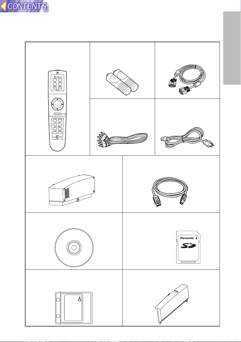
Slot cover (for projector LAN card)
(TKKL5243 x1)
(PT-L780NTU only)
Remote control unit
(N2QAEA000011 x1)
Power coed
(K2CG3FZ00008 x 1)
AAA batteries for
remote control unit (x2)
RGB signal cable [3.0 m
(9´10˝), K1HB15FA0001
x1]
Video/Audio cable [3.0
m (9´10˝),
K2KA2FA00001 x 1]
Accessories
Check that all of the accessories shown below have been included with your
projector.
CD-ROM (TQBH9003x1)
(PT-L780NTU only)
Protective case for SD memory card
(RP-SDCC0 x1)
(PT-L780NTU only)
Cable cover
(TXFKR01VJN1 x1)
SD memory card (8 MB,
RP-SD008BEZ0 x1)
(PT-L780NTU only)
USB cable
(3.0 m, K1HB04FD0002 x 1)

12
Precautions on handling
Cautions when moving the projector
Be sure to attach the lens cover before moving the projector.
The projection lens is extremely susceptible to vibration and shocks. Be
careful not to subject it to excessive vibration and shock when moving the
projector.
Cautions regarding setting-up
Observe the following at all times when setting up the projector.
Avoid setting up in places which are subject to vibration or shocks.
If the projector is set up in locations with strong vibration, such as near a
motor, or if it is installed inside a vehicle or on board a ship, the projector
may be subjected to vibration or shocks which can damage the internal parts
and cause malfunctions or accidents. Accordingly, set up the projector in a
place which is free from such vibrations and shocks.
Do not set up the projector near high-voltage power lines or near
motors.
The projector may be subject to electromagnetic interference if it is set up
near high-voltage power lines or motors.
If installing the projector to the ceiling, ask a qualified technician to
carry out all installation work.
If the projector is to be suspended from the ceiling, you will need to purchase
the separate installation kit (Model No.: ET-PK780). Furthermore, all
installation work should only be carried out by a qualified technician.
If using this projector at high elevations (above 1 400 m), set the FAN
CONTROL to HIGH. (Refer to page 47.)
Failure to observe this may result in malfunctions.
Notes on use
In order to get the best picture quality
If outside light or light from indoor lamps is shining onto the screen, the
images projected will not have good contrast. Draw curtains or blinds over
any windows and turn off any fluorescent lights near the screen to prevent
reflection.
Do not touch the surfaces of the lens with your bare hands.
If the surface of the lens becomes dirty from fingerprints or anything else, this
will be magnified and projected onto the screen. Moreover, when not using
the projector, retract the lens and then cover it with the accessory lens cover.

13
Preparation
About the screen
If the screen you are using is dirty, damaged or discolored, attractive
projections cannot be obtained. Do not apply any volatile substances to the
screen, and do not let it become dirty or damaged.
About the lamp
The lamp may need to be replaced earlier due to variables such as a
particular lamp’s characteristics, usage conditions and the installation
environment, especially when it is subjected to a continuous use for more
than 10 hours.
About the SD memory card (PT-L780NTU only)
Static electricity from the human body can damage the SD memory card. To
prevent this, you should touch a nearby metallic object such as an aluminium
sash or a door knob to dissipate the static charge from your body.
About the card slot (PT-L780NTU only)
Make sure that there are no foreign objects inside the slot when inserting the
SD memory card or an optional wireless card. Failure to observe it may
damage the card and the slot.
Before carrying out cleaning and maintenance, be
sure to disconnect the power cord plug from the
wall outlet.
Wipe the cabinet with a soft, dry cloth.
If the cabinet is particularly dirty, soak the cloth in water with a small amount
of neutral detergent in it, squeeze the cloth very well, and then wipe the
cabinet. After cleaning, wipe the cabinet dry with a dry cloth.
If using a chemically-treated cloth, read the instructions supplied with
the cloth before use.
Do not wipe the lens with a cloth that is dusty or which produces lint.
If any dust or lint gets onto the lens, such dust or lint will be magnified and
projected onto the screen. Use a blower to clean any dust and lint from the
lens surface, or use a soft cloth to wipe off any dust or lint.
14
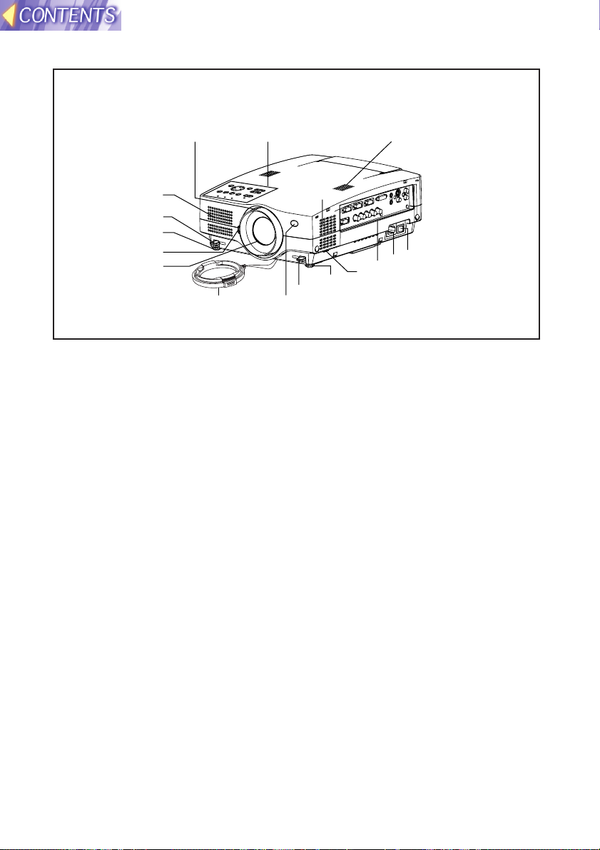
Location and function of each part
# Projector control panel
(page 16)
$ Focus ring
(pages 31 and 50)
% Air inlet ports
Do not cover these ports.
& Leg adjuster buttons(L/R)
(page 30)
These buttons are used to unlock
the front adjustable legs. Press to
adjust the angle of tilt of the
projector.
' Front adjustable legs(L/R)
(page 30)
( Lens release button
(page 51)
This button is used when using a
projection lens that is sold
separately.
) Projection lens
* Lens cover
+ Remote control signal receptor
(page 22)
, Air filter
(page 64)
- Connector panel
(page 18)
. Power input socket (AC IN)
(page 30)
The accessory power cord is
connected here.
Do not use any power cord other
than the accessory power cord.
/ MAIN POWER switch
(pages 30 and 31)
0 Speaker
Projector <Top, right and front>
$
%
&
'
(
)
#
0
%
/
.
-
,
'
&
+*
15
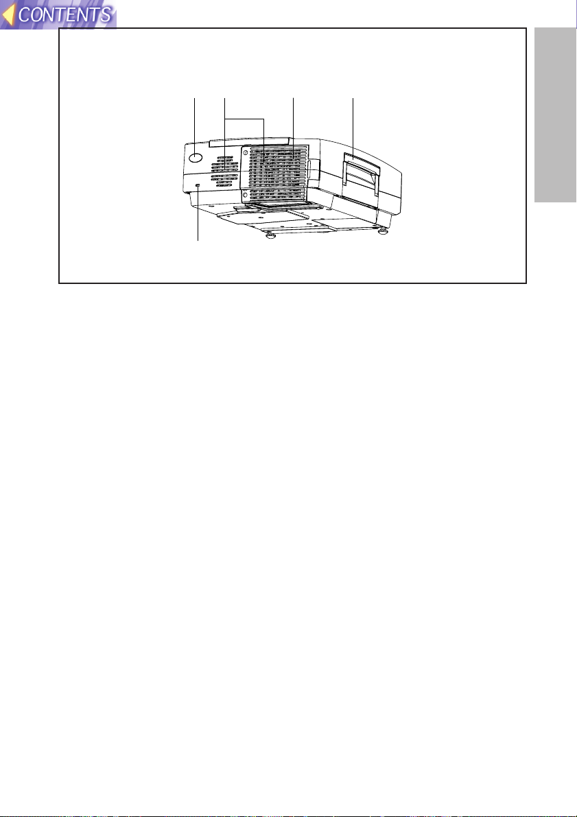
Preparation
# Remote control signal receptor
(page 22)
$ Security lock
This can be used to connect a
commercially-available theftprevention cable (manufactured
by Kensington). This security lock
is compatible with the Microsaver
Security System from
Kensington. Contact details for
this company are given below.
Kensington Technology Group
ACCO Brands Inc.
2855 Campus Drive
San Mateo, CA 94403 USA
Tel (650)572-2700
Fax (650)572-9675
http://www.kensington.com/
http://www.gravis.com/
NOTE:
B Information given above may be
changed in future.
% Carrying handle
& Lamp unit holder
(page 65)
' Air outlet port
Do not cover this port.
WARNING
Do not bring your hands or other
objects close to the air outlet
port.
B Heated air comes out of the air
outlet port. Do not bring your
hands or face, or objects which
cannot withstand heat close to
this port, otherwise burns or
damage could result.
NOTE:
B During projection of an image, the
cooling fan will operate, emitting
a small noise as it operates.
Turning the lamp on or off will
cause this noise to increase a
little.
B By using the OPTION menu to
set “LAMP POWER” to “LOW”,
the operating sound of the fan
can be reduced. (Refer to page
47.)
Projector <Back and bottom>
'
#
$
&
%
16
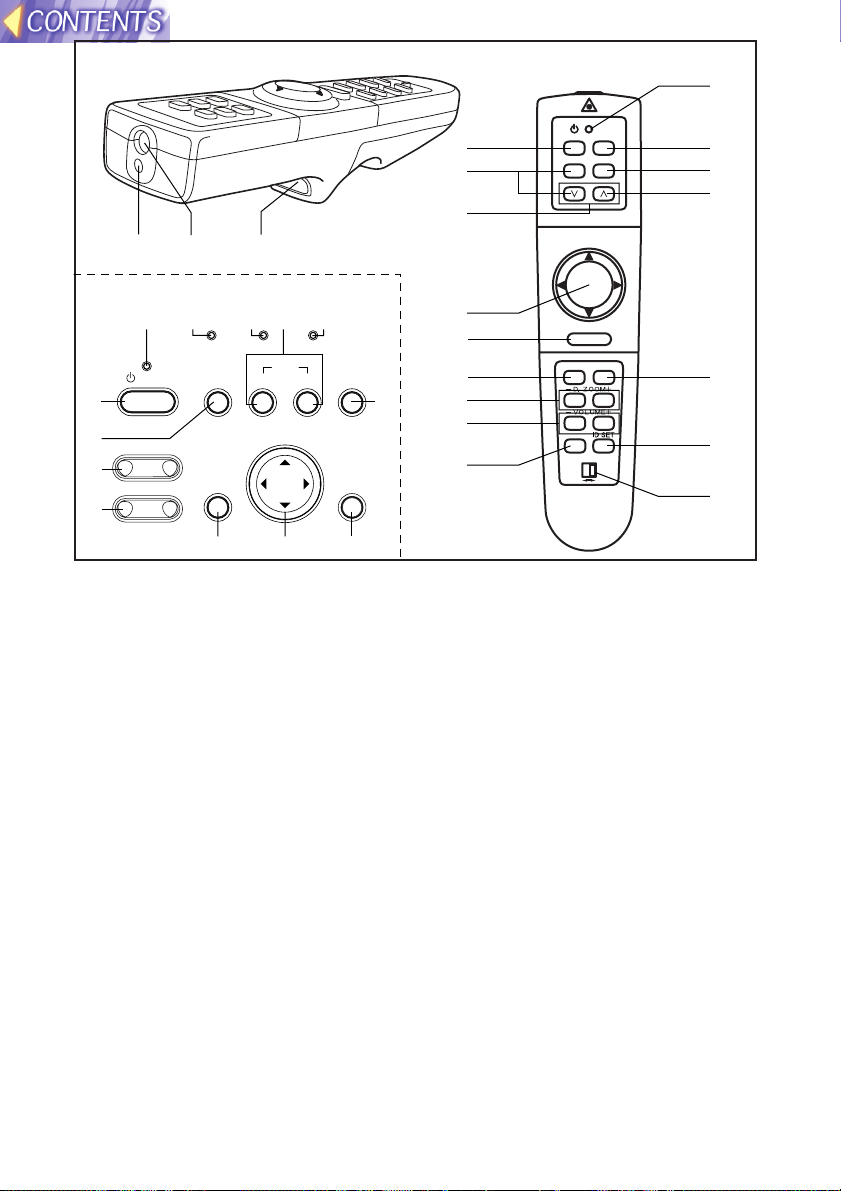
Remote control unit
# Power indicator
(pages 30, 31 and 47)
This indicator illuminates red when
the MAIN POWER switch is turned
on (standby mode), and illuminates
green when the power is turned on
and a picture starts to be projected.
(PT-L780NTU only)
When the WEB STANDBY is set
to "ON", the cooling fan operates
and the power indicator on the
projector flashes slowly in red.
$ RGB INPUT indicator
This indicator illuminates when a
signal is input into the connector
that is selected with the input
select buttons.
%LAMP indicator (page 61)
This indicator illuminates when it is
time to replace the lamp unit. It flashes
if a circuit abnormality is detected.
& Input select (RGB, VIDEO)
buttons (page 30)
'TEMP indicator (page 60)
This indicator illuminates if an
abnormally high temperature is
detected inside the projector or
around it. If the temperature rises
above a certain level, the power
supply will be turned off
automatically and the indicator
will illuminate or flash.
( POWER button
(pages 30 and 31)
) AUTO SETUP button
(pages 30 and 62)
If this button is pressed while a
picture is being projected, the
projection settings will be
adjusted automatically in
accordance with the signal being
input. In addition, the angle of tilt
of the projector will be
automatically detected and
adjusted in order to correct any
keystone distortion. (“AUTO
SETUP” will appear on the
screen during adjustment.) Set
“AUTO KEYSTONE” in the
OPTION menu to “OFF” to
prevent any deterioration of the
picture as a result of keystone
correction. However, keystone
distortion may not be corrected
RGBVIDEOAUTO SETUP
ON(G)
STANDBY(R)
ENTER
MENU
POWER SHUTTER
INPUT
TEMP
LAMPRGB INPUT
– FOCUS +
–
ZOOM +
POWER
RGB
VIDEO
R-CLICK
LASER
MENU
PAG E
ENTER
FREEZE SHUTTER
FUNC1
Computer Pro jector
SETUP
AUTO
(
&
)
4
5
+
3
,
-
6
*
:
7
8
9
;
0
12
'
&
%
$
+,
-
*
#
(
)
/
.
Projector control panel

17
Preparation
properly when using a lens that is
sold separately. Refer to page 42
for details on correcting keystone
distortion manually.
*SHUTTER button (page 46)
This button is used to
momentarily turn off the picture
and sound. However, keystone
distortion may not be corrected
properly when using a lens that is
sold separately. Refer to page 42
for details on correcting keystone
distortion manually.
+MENU button (pages 32 and 35)
This button is used to display the
menu screens. When a menu
screen is being displayed, this
button can be used to return to a
previous screen or to clear the
screen.
, Arrow (
FFGGII
and HH) buttons
(page 35)
These buttons are used to select
and adjust items in the menu
screens.
*When in computer operating
mode, these buttons on the
remote control unit function
differently. (page 21)
-ENTER button (page 35)
This button is used to accept and
to activate items selected in the
on-screen menus.
*When in computer operating
mode, this button on the remote
control unit operates differently.
(page 21)
.FOCUS +/- buttons (page 31)
These buttons are used to adjust
the projected image focus.
/Zoom +/- buttons (page 31)
These buttons are used to adjust
the projected image size.
0Laser emitter (page 20)
1Infrared emitter (page 22)
2Click button (page 21)
This button can be used when the
operating mode select switch is
moved to the left (Computer).
3PAGE button (page 21)
This button can be used when the
operating mode select switch is
moved to the left (Computer).
4Operation indicator (page 20)
This indicator illuminates while a
laser beam is being emitted
(while the LASER button is being
pressed). It flashes when any
other buttons are being pressed.
5LASER button (page 20)
A beam of laser light is emitted while
this button is being pressed. This
laser beam can be used as a pointer
to point to something on the screen.
6FREEZE button (page 36)
This button is used to
momentarily freeze projection so
that a still picture is displayed.
7D.ZOOM +/- buttons (page 37)
These buttons are used to
enlarge the projected image.
8 VOLUME +/- buttons
These buttons are used to adjust
the volume of the sound output
from the projector’s built-in
speakers. Refer to page 45 for
details on how to adjust the
volume using the buttons on the
projector control panel.
9 FUNCTION (FUNC1) button
(pages 42, 45 and 48)
This button can be used for 1)
switching on and off the sound
volume and 2) entering into the
keystone distortion correction mode.
Use the FUNC1 item in the OPTION
menu to select which you wish to use.
:ID SET button (page 23)
This button is used to set the IDs
into the remote control unit when
using multiple projectors with a
single remote control unit.
; Operating mode (Computer,
Projector) select switch
(page 21)
Move this switch to the left side to
use the remote control unit to
operate a computer, and move it
to the right side to operate the
projector.

18
<Connector panel>
# USB port
(page 21)
The remote control unit can be
used as
a personal computer
mouse by connecting the
projector to
a personal computer
with the supplied USB cable.
(4-pin square connector)
$ SERIAL connector
(pages 26, 27 and 58)
This connector is used to connect
a personal computer to the
projector in order to externally
control the projector. (RS-232C
compatible)
% RGB1 IN connector
(pages 26 and 27)
This connector is used to input
RGB signals and YPBPR signals.
& RGB2 IN/RGB OUT connector
(pages 26 and 27)
This connector is used to input or
output RGB signals and YPBPR
signals. Use the RGB2 SELECT
item in the OPTION menu to
select whether you want input or
output with this connector.
' DVI-D IN connector
(page 27)
This connector is used to input
DVI-D signals.
( AUDIO OUT jack
(pages 26 and 27)
This jack is used to output the
audio signals which are input to
the projector. If audio equipment
is connected to this jack, no
sound will be output from the
built-in speakers.
) S-VIDEO IN connector
(pages 26 and 44)
This connector is used to input
signals from a S-VIDEOcompatible equipment such as a
video deck. The connector is S1
signal compatible, and it
automatically switches between
16:9 and 4:3 aspect ratios in
accordance with the type of
signal being input.
* AUDIO IN L-R (for VIDEO/S-
VIDEO) jacks
(page 26)
Only one system is provided, so
connect the appropriate
connector when using VIDEO or
S-VIDEO.
+ Remote control connector
(page 57)
This connector is used to control
the projector from the Remote
Control set up in Wired mode.
, RGB3 (YPBPR) IN connector
(pages 26 and 27)
This connector is used to input
RGB2 IN/RGB OUT
USB
SERIAL
REMOTE
RGB1 IN
R VDSYNC/HDB/B-Y/PB
R/R-Y/P
G/Y
RGB3 IN
& ( )%$#
'
DVI-D IN
AUDIO OUT
RGB AUDIO IN
VIDEO IN
S-VIDEO IN
L
R
AUDIO IN
*
, - .+
LOCK
)
(
19
Preparation
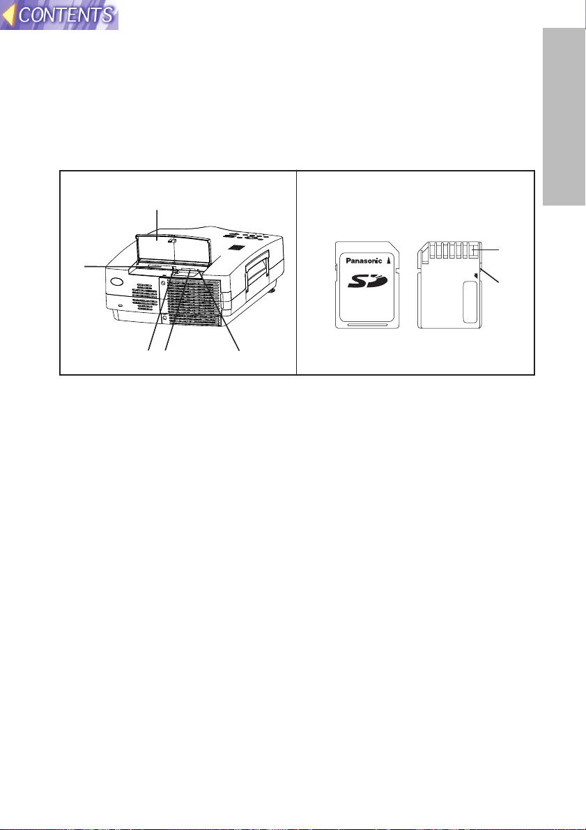
'% &
$
#
<SD memory card><Card slot>
Front Back
# Slot cover
Covers the card slots. When
using an optional projector LAN
card, replace the slot cover (refer
to page 54).
$ Card slot
Insert an optional wireless card or
a projector LAN card into here.
% Eject switch
Use to remove an optional
wireless card or projector LAN
card from the card slot.
& Access lamp
Flashes while the projector is
being accessed for reading or
writing the data in the SD
memory card.
' SD memory card slot
Insert the SD memory card into
here.
( Metal terminals
These terminals are for
connecting the SD memory card
to the projector’s card slot. Do not
touch the metal terminals with
hands or metal objects, attach
stickers to them, or allow them to
become contaminated in any
way.
) Write-protect switch
If the write-protect switch on the
SD memory card is moved to the
LOCK position, it will not be
possible to use any file editing
functions such as deleting or
moving image files.
(PT-L780NTU only)
RGB signals and YPBPR signals.
- RGB AUDIO IN jack
(pages 26 and 27)
Only one system is provided, so
connect the appropriate
connector when using RGB1,
RGB2 or RGB3.
. VIDEO IN jack
(page 26)
This jack is used to input video
signals from a video equipment
such as a video deck.
20
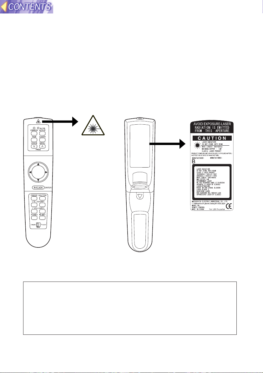
Using the remote control unit
PUSH
Laser beam pointer
The laser beam emitted from the remote control can be used as a pointer by
pointing forward to the screen.
While the LASER button is being pressed, the laser beam is being emitted
and the operating indicator illuminates.
Do not look into the laser emitter of the remote control unit or point the laser
beam towards other people, otherwise damage to eyes may occur.
Caution
B Use of controls or adjustments or performance of procedures
other than those specified herein may result in hazardous
radiation exposure.
B This remote control unit cannot be repaired.
N2QAEA000011

21
Preparation
Wireless mouse
You can use the remote control as
a personal computer
mouse. Set the Mode
(Projector/Computer) switch on the remote control unit to “Computer”and
connect the projector’s USB port to
a personal computer
counterpart with the
BFor Windows (Versions 98SE, Me, 2000 and XP), you can use the
standard mouse driver which comes bundled with the operating
system.
USB
REMOTE
SERIAL
RGB1 IN
RGB2 IN/RGB
R/R-Y/P
R SYNB/B-Y/PB
RGB3 IN
G/Y
POWER
RGB
VIDEO
R-CLICK
LASER
MENU
PAGE
ENTER
FREEZE SHUTTER
FUNC1
Computer Pro jector
SETUP
AUTO
Page
buttons
FGIH button
Click button
R-CLICK button
Mode switch
(Computer/Projector)
Mode switch (Computer/Projector)
Move the mode switch to the
“Computer” position.
B Page buttons
^
: Functions as the Page Up button
on
a personal computer
keyboard.
v: Functions as the Page Down
button on
a personal computer
keyboard.
B Arrow (
FFGGIIHH
) buttons
These buttons can move the cursor
on
a personal computer
’s screen as
the
personal computer
mouse.
B R-CLICK button
This button functions as the right
button on
a personal computer
mouse.
B Click button
This button functions as the left button
on
a personal computer
mouse.
NOTE:
B The optional wireless receiver
(ET-RMRC1) is needed for
a personal
computer
not equipped with a USB
port.
Projector
Accessory USB cable
C
omputer
equipped with a USB port
22
B If there are any obstacles in between
the remote control unit and the
receivers, the remote control unit may
not operate correctly.
B
If strong light is allowed to shine onto
the remote control signal receiver,
correct remote control operation may
not be possible. Place the projector as
far away from light sources as possible.
B If facing the remote control unit
toward the screen to operate the
projector, the operating range of the
remote control unit will be limited by
the amount of light reflection loss
caused by the characteristics of the
screen used.
NOTE:
B If there are any obstacles in between
the remote control unit and the
receivers, the remote control unit may
not operate correctly.
B
If strong light is allowed to shine onto
the remote control signal receiver,
correct remote control operation may
not be possible. Place the projector as
far away from light sources as possible.
B If facing the remote control unit
toward the screen to operate the
projector, the operating range of the
remote control unit will be limited by
the amount of light reflection loss
caused by the characteristics of the
screen used.
B Do not drop the remote control unit.
B Keep the remote control unit away from liquids.
B Remove the batteries if not using the remote control unit for long periods.
B Do not use rechargeable batteries.
NOTE:
B Do not drop the remote control unit.
B Keep the remote control unit away from liquids.
B Remove the batteries if not using the remote control unit for long periods.
B Do not use rechargeable batteries.
Operating range
If the remote control unit is held so
that it is facing directly in front of the
remote control signal receptors on
the front or rear of the projector, the
operating range is within
approximately 7 m (23´) from the
surfaces of the receptors.
Furthermore, the remote control unit
can be operated from an angle of
±30° to the left or right and ±15°
above or below the receptors.
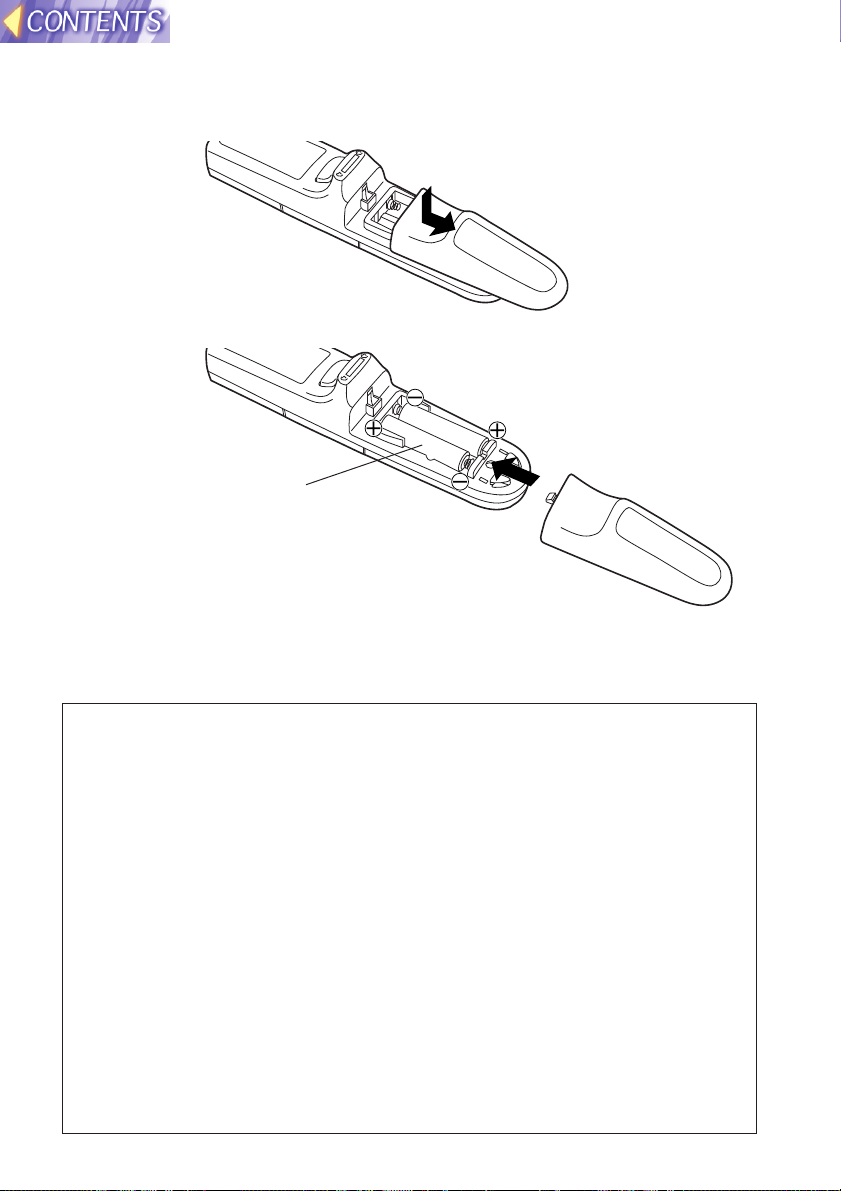
# Open the cover.
AAA batteries
(two)
$ Insert the batteries so that the
polarities are correct, and then close the
cover.
Inserting the batteries

23
Preparation
Setting the projector IDs number for remote control unit
When controlling multiple projectors individually or simultaneously with a
single remote control unit, projector IDs must be set into the remote control
unit as described in the following steps.
#Press the ID SET button on the remote control unit.
ID number “ALL” will be displayed on the screen.
$Press and hold the ID SET button for more than 2 seconds.
The ID number will change into “1”. The ID SET button will now toggle
through ID numbers “2”, “3”, “ALL” and “1” each time it is subsequently
pressed.
%Select the ID number you wish and then press the ENTER button.
When the projector ID coincides with the remote control unit
<If the MAIN POWER is ON>
The ID number will be displayed in white on the screen.
If the projector ID and ID for the remote control unit are not the same, the
projector ID is displayed in green.
<If the projector is in standby mode>
The Power indicator on the projector will flash for 5 seconds.
If the projector ID and ID for the remote control unit are not the same, the
Power indicator will stay illuminated red.
NOTE:
B The projector ID number in the remote control unit is set to “ALL” by
default. It is therefore not necessary to set a projector ID number when
only one projector is used.
B The projector can be turned ON/OFF from the remote control unit only if
the projector ID is set in the remote control unit. For more details on
projector ID setting, see page 48.

24
Connections
Notes on connections
B Read the instruction manual for each system component carefully before
connecting it.
B Turn off the power supply for all components before making any
connections.
B If the cables necessary for connecting a component to the system are not
included with the component or available as an option, you may need to
fashion a cable to suit the component concerned.
B If there is a lot of jitter in the video signal which is input from the video
source, the picture on the screen may flicker. In such cases, it will be
necessary to connect a TBC (time base corrector).
B The projector has built-in speakers. However, you will need to connect a
separate audio system to the AUDIO OUT jack if your needs specify high
sound volumes. No sound will come out of the projector’s built-in speakers
while the AUDIO OUT jack is being used.
B It may not be possible to connect some types of computer. Refer to the list
of compatible signals on page 63.
B The pin layout and signal names for the S-VIDEO IN connector are shown
below.
Pin No. Signal
#
Earth (Luminance signal)
Earth (Color signal)
Luminance signal
Color signal
$
%
&
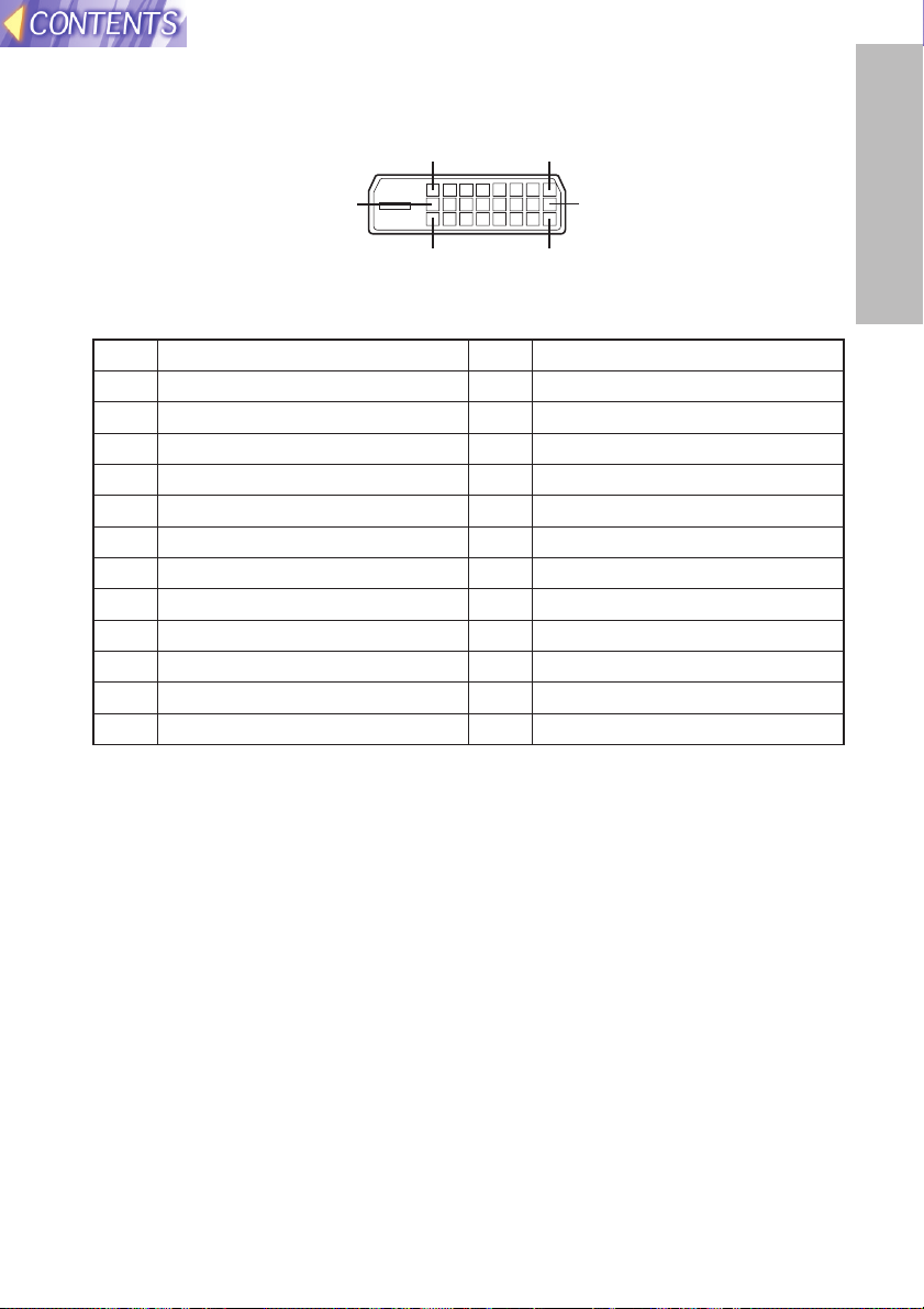
B The pin layout and signal names for the RGB/YPBPR (RGB1 IN/RGB2 IN)
connector are shown below.
Pin No. Signal
#
R/PR
G/G·SYNC/Y
B/PB
SDA
$
%
.
/
HD/SYNC
0
VD
1
SCL
Pin + is spare.
Pins &–*, , and - are for earth.
Pins . and 1 functions are only valid when
supported by the computer.
#$
%&
External view
-1
#'
,(
External view
25
Preparation
B The pin assignments on the DVI-D input connector are as follows
(interface with TMDS connector on a personal computer)
View from mating side
Pin No.
Signal
Pin No.
Signal
#
T.M.D.S data 2-
/
T.M.D.S data 3+
$
T.M.D.S data 2+
0
+5 V
%
T.M.D.S data 2/4 shield
1
Ground
&
T.M.D.S data 4-
2
Hot plug sense
'
T.M.D.S data 4+
3
T.M.D.S data 0-
(
DDC clock
4
T.M.D.S data 0+
)
DDC data
*
-
6
T.M.D.S data 5-
+
T.M.D.S data 1-
7
T.M.D.S data 5+
,
T.M.D.S data 1+
8
T.M.D.S clock shield
-
T.M.D.S data1/3 shield
.
T.M.D.S data 3-
:
T.M.D.S clock-
5
T.M.D.S data 0/5 shield
9
T.M.D.S clock+
#
*
3:
2
+
26
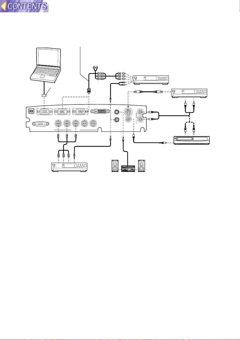
Example of connecting to video equipments
USB
DVI-D IN
REMOTE
SERIAL
RGB1 IN
RGB2 IN/RGB OUT
AUDIO OUT
RGB AUDIO IN
VIDEO IN
AUDIO IN
S-VIDEO IN
R
L
R/R-Y/P
R VDSYNC/HDB/B-Y/PB
RGB3 IN
G/Y
D-sub 15 (male) - BNC5 (female)
adapter cable (sold separately)
Red (connect to PR signal connector)
Blue (connect to PB signal connector)
Green (connect to Y signal connector)
Digital broadcast
tuner or DVD player
D-sub 9-pin
(male)
DVD player Audio system
Video deck
NOTE:
B Only one audio system circuit is available for the AUDIO IN L-R jacks for
S-VIDEO/VIDEO signals, so if you wish to change the audio input source,
you will need to remove and insert the appropriate plugs.
B Only one audio system circuit is available for the RGB AUDIO IN jacks, so
if you wish to change the audio input source, you will need to remove and
insert the appropriate plugs.
B If an audio system is connected to the AUDIO OUT jack, the sound
volume balance can be controlled by the remote control unit which is
supplied with the projector.
B If the video signal source is connected using a cable with a BNC
connector plug, use a BNC/RCA adapter (sold separately) to convert the
cable end to an RCA plug-type jack.
BRefer to page 63 for a list of compatible YP
BPR signals which can be input
to the projector.
B If the signal cables are disconnected or if the power supply for the
computer or video deck is turned off while the digital zoom function is
being used, this function will be cancelled.
Computer for
control use
DVD player
Red (connect to P
R signal connector)
Blue (connect to PB signal connector)
Green (connect to Y signal connector)

27
Preparation
USB
DVI-D IN
REMOTE
SERIAL
RGB1 IN
RGB2 IN/RGB OUT
AUDIO OUT
RGB AUDIO IN
VIDEO IN
AUDIO IN
S-VIDEO IN
R
L
R/R-Y/P
R VDSYNC/HDB/B-Y/PB
RGB3 IN
G/Y
1 623 45
ON DIP
D-sub 9-pin
(male)
Computer for
control use
Computer
NOTE:
B It is better to shut down the computer before turning off the MAIN POWER
switch of the projector.
BRefer to the list of compatible signals on page 63 for the types of RGB
signals which can be input to the projector by connecting a computer.
BDo not input the signal to the RGB2 IN/RGB OUT connector when the
RGB2 SELECT item in the OPTION menu is set to OUTPUT. (Refer to
page 46.)
Example of connecting to computer
Monitor
Audio system
Refer to the accessory CD-ROM for details on connecting the
projector to a personal computer by means of a wireless or wired
network using an optional wireless card or projector LAN card.
(PT-L780NTU only)
Computer
Computer with
DVI-D OUT connector
DVI cable
(Option)
(TY-SCDV03)
28
Setting-up
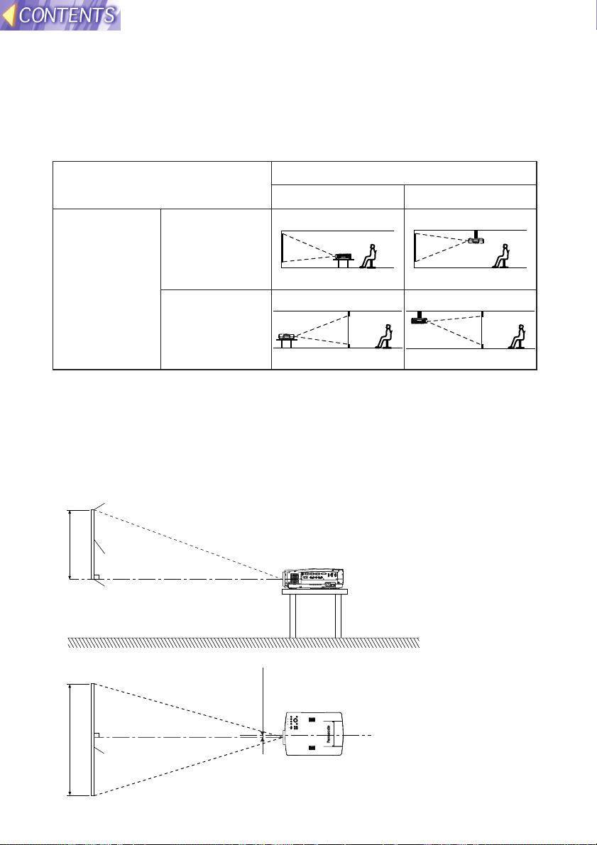
Projection methods
In way of installing projector, any one of the following four projection methods
are used. Select whichever projection method matches the setting-up
method. (The projection method can be set from the OPTION menu. Refer to
page 47 for details.)
FRONT/REAR
FRONT
REAR
(Factory default setting)
NOTE:
B You will need to purchase the separate ceiling bracket (ET-PK780) when
using the ceiling installation method.
Projector position
DESK/CEILING
DESK CEILING
L
L
SH
SW
25(31/32)
L: Projection distance
SH: Image height
SW:Image width
Top edge of screen
Screen
Bottom edge of screen
Screen
<Units: mm (inch)>

29
Preparation
1.01 m(40˝) 0.61 m(2´) 0.81 m(2´8˝) 1.6 m(5´2˝) 2.0 m(6´6˝)
1.27 m(50˝) 0.76 m(2´6˝) 1.02 m(3´4˝) 2.0 m(6´6˝) 2.6 m(8´6˝)
1.52 m(60˝) 0.91 m(3´) 1.22 m(4´) 2.4 m(7´10˝) 3.1 m(10´2˝)
1.77 m(70˝) 1.07 m(3´6˝) 1.42 m(4´8˝) 2.8 m(9´2˝) 3.6 m(11´9˝)
2.03 m(80˝) 1.22 m(4´) 1.63 m(5´4˝) 3.2 m(10´5˝) 4.2 m(13´9˝)
2.28 m(90˝) 1.37 m(4´6˝) 1.83 m(6´) 3.6 m(11´9˝) 4.7 m(15´5˝)
2.54 m(100˝) 1.52 m(5´) 2.03 m(6´8˝) 4.0 m(13´1˝) 5.3 m(17´4˝)
3.81 m(150˝) 2.29 m(7´6˝) 3.05 m(10´) 6.1 m(20´) 7.9 m(25´11˝)
5.08 m(200˝) 3.05 m(10´) 4.06 m(13´4˝) 8.1 m(26´6˝) 10.6 m(34´9˝)
6.35 m(250˝) 3.81 m(12´6˝) 5.08 m(16´8˝) 10.1 m(33´1˝) 13.3 m(43´7˝)
7.62 m(300˝) 4.57 m(15´) 6.10 m(20´) 16.0 m(52´5˝)
Projection distances
Setting-up dimensions which are not given in the above table can be
calculated using the formulas below.
If the screen size (diagonal) is SD (m), then the following formula is used to
calculate the projection distance for the wide lens position (LW) and the
projection distance for the telephoto lens position (LT).
For 16:9 aspect ratios, the following formula can be used to calculate the
projection distance.
NOTE:
B The dimensions in the table above and the values obtained from the
above formulas may contain slight errors.
B If you use the projection distance for the 16:9 screen, the
4:3 projection image overflows the screen at the top and
bottom.
B If you set up the projector vertically, it may cause to
damage the projector.
B It is recommended that you set up the projector in
a place that is tilted at less than
±35°. Setting up
the projector in places that are tilted at more than
±35° may cause malfunctions.
Make sure that enough space is kept for the air
outlet port.
Screen size (4:3)
Diagonal
length
Height
(SH)
Width
(SW)
Projection distance (L)
Wide
(LW)
Telephoto
(LT)
LW=0.0443xSD/0.0254-0.080
LT=0.0586xSD/0.0254-0.0774
LW=0.0407xSD/0.0254-0.080
LT=0.0538xSD/0.0254-0.0774
12.2 m(40´)
R
$
%
30
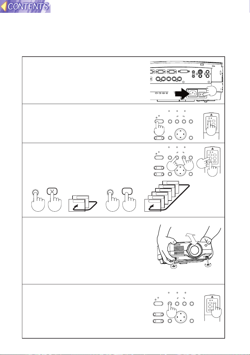
Starting to use
Turning on the power
Please ensure that all preparations have been completed before turning on
the power. (Refer to pages 24 – 29.)
POWER
RGB
VIDEO
LASER
MENU
PAGE
SETUP
AUTO
RGBVIDEOAUTO SETUP
ON(G)
STANDBY(R)
ENTER
MENU
POWER SHUTTER
INPUT
TEMP
LAMPRGB INPUT
– FOCUS +
–
ZOOM +
# Remove the lens cover.
$ Connect the accessory power cord.
% Press the MAIN POWER switch to
the “l” side to turn on the power.
The power indicator on the projector
will illuminate red.
& Press the POWER button.
The power indicator on the projector
will flash green. After a short period,
the indicator will illuminate green, and
a picture will be projected.
' Press the input select (RGB, VIDEO)
button to select the input signal.
The input signal selected will change
as shown at below each time an input
select button is pressed.
( While pressing the adjuster buttons,
adjust the forward/back angle of tilt
of the projector.
To make fine adjustments to the angle of
tilt of the projector, turn the front
adjustable legs. (The front adjustable legs
will be locked if they are fully extended
and then turned anticlockwise. Turn them
back clockwise to release the lock.)
RGBVIDEO
S-VIDEO
VIDEO
RGB
VIDEO
SD CARD
NETWORK
DVI
RGB3
RGB2
RGB1
) Press the AUTO SETUP button to
initiate automatic positioning.
The automatic positioning is only for vertical
keystone distortion. To correct the
horizontal keystone distortion or when
keystone distortion has not been corrected
to the optimum level, carry out the keystone
correction as described on page 42.
POWER SHUTTER
STANDBY(R)
ON(G)
– FOCUS +
ZOOM +
–
TEMP
LAMPRGB INPUT
INPUT
RGBVIDEOAUTO SETUP
MENU
ENTER
AUTO
POWER
SETUP
LASER
RGB
MENU
VIDEO
PAGE
TEMP
LAMPRGB INPUT
INPUT
POWER SHUTTER
STANDBY(R)
ON(G)
– FOCUS +
ZOOM +
–
RGBVIDEOAUTO SETUP
MENU
ENTER
AUTO
POWER
SETUP
RGB
LASER
VIDEO
MENU
PAGE
 Loading...