

Page 1
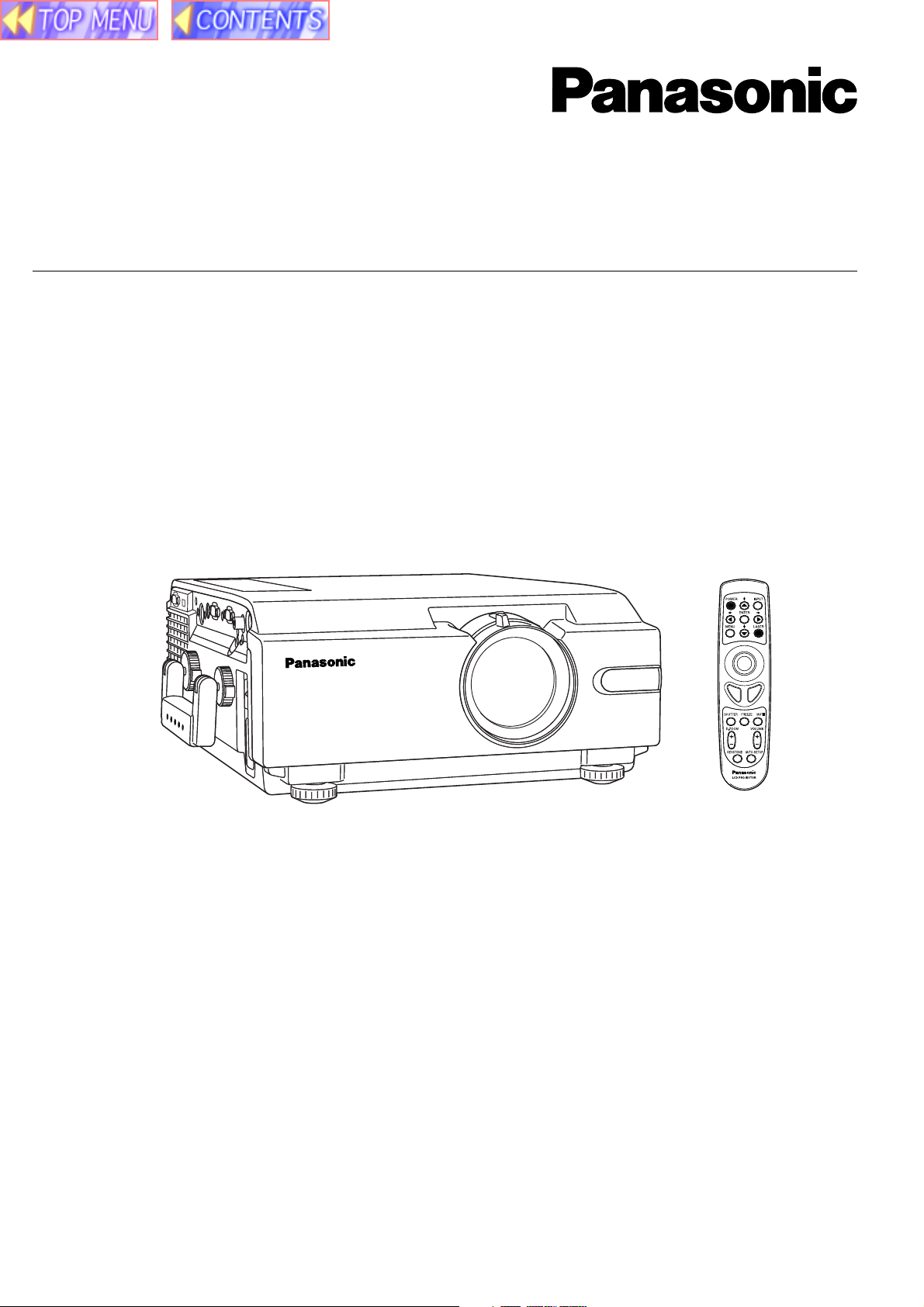
LCD PROJECTOR
Operating Instructions
Model No. PT-L759VU /
PT-L759XU
Please read these instructions completely before operating this LCD Projector.
This operating instruction book is designed for use with models PT-L759VU and PT-L759XU.
Illustrations in this manual show the PT-L759XU. Features may vary, so please read carefully.
Page 2
Dear Panasonic Customer:
This instruction manual provides all the necessary operating information that you might require. We hope it will help you
to get the most performance out of your new product, that you will be pleased with your Panasonic LCD Projector.
For your own protection and prolonged operation of your LCD Projector, please be sure to read the “Important
Safeguards” carefully, before use.
Things You Should Know
Caution:
This equipment has been tested and found to comply with the limits for a Class B digital device, pursuant to Part 15
of the FCC Rules. These limits are designed to provide reasonable protection against harmful interference in a
residential installation. This equipment generates, uses, and can radiate radio frequency energy and, if not installed
and used in accordance with the instructions, may cause harmful interference to radio communications. However,
there is no guarantee that interference will not occur in a particular installation. If this equipment does cause harmful
interference to radio or television reception, which can be determined by turning the equipment off and on, the user is
encouraged to try to correct the interference by one or more of the following measures:
– Reorient or relocate the receiving antenna.
– Increase the separation between the equipment and receiver.
– Connect the equipment into an outlet on a circuit different from that to which the receiver is connected.
– Consult the dealer or an experienced radio/TV technician for help.
Declaration of Conformity
Model Number: PT-L759VU / PT-L759XU
Trade Name:
Responsible party: Matsushita Electric Corporation of America.
Address: One Panasonic Way Secaucus New Jersey 07094
Telephone number: 1-800-528-8601
This device complies with Part 15 of the FCC Rules, Operation is subject to the following two conditions: (1) This
device may not cause harmful interference, and (2) this device must accept any interference received, including
interference that may cause undesired operation.
FCC Warning:
To assure continued FCC compliance, use only the provided grounded power supply cord and prevent undesirable
interference, use only the provided shielded VGA cable with 2 ferrite cores while connecting LCD to computer and all
other connecting cables should be shielded. Any changes or modifications not expressly approved by the party
responsible for compliance could void the user’s authority to operate this equipment.
Warning: (E.U. only)
To assure continued CE Mark compliance, use only the provided earthed power supply cord and prevent undesirable
interference, use only the provided shielded VGA cable with 2 ferrite cores while connecting LCD to computer and all
other connecting cables should be shielded.
Any changes or modifications not expressly approved by the party responsible for compliance could void the user‘s
authority to operate this equipment.
2
Page 3

Table of Contents
Dear Panasonic Customer ........................................................................................................ 2
Getting
Started
Basic
Operation
Important Safeguards ............................................................................................................... 4
LCD Projector Features ............................................................................................................ 6
Contents of LCD Projector Box ................................................................................................. 7
Product Information ................................................................................................................... 8
Before using the Remote Control Unit .................................................................................... 10
Standard Setting-up Positions ................................................................................................. 12
Screen Requirements ............................................................................................................. 13
Turning the power on and off................................................................................................... 14
Adjusting the LCD Projector Projection Angle......................................................................... 15
Adjusting the Lens................................................................................................................... 16
Changing the input signal........................................................................................................ 17
Basic LCD Projector Operation ............................................................................................... 18
Menu operation guide ............................................................................................................. 19
Setting-up Positions and Changing the Projection Mode ........................................................ 22
Setting the Screen Type .......................................................................................................... 23
Digital Variable Compression .................................................................................................. 24
Keystone Correction function .................................................................................................. 25
Signals that can be Input......................................................................................................... 26
Selecting the Image Quality .................................................................................................... 29
Adjusting the Picture to the Desired Setting............................................................................ 30
Adjusting the White Balance ................................................................................................... 31
Using the Auto Setup Feature ................................................................................................. 32
Adjusting the Image Position, Dot Clock and Phase ............................................................... 33
Useful
Functions
Other
Information
Using Other Useful Functions ................................................................................................. 34
Projecting the DTV Format Signal........................................................................................... 39
Changing the RGB2 IN/RGB1 OUT Terminal ......................................................................... 40
System Configuration Example ............................................................................................... 41
Video/Personal Computer Cables & Adaptors ........................................................................ 44
Using the SERIAL connector (RS-232C) ................................................................................ 46
Wireless mouse and keyboard ................................................................................................ 48
Removing and Attaching the Carrying Handle ........................................................................ 49
Status Code Display Indications ............................................................................................. 50
Cleaning the Air Filter.............................................................................................................. 51
Lamp Replacement ................................................................................................................. 52
Specifications .......................................................................................................................... 55
Before Requesting Service ..................................................................................................... 57
Cher Client: ............................................................................................................................. 58
Notes importantes concernant la sécurité ............................................................................... 59
Utilisation de l’indicateur laser sur la télécommande .............................................................. 61
Remplacement de la lampe .................................................................................................... 61
Lieber Panasonic-Kunde, ........................................................................................................ 63
Wichtige Sicherheitshinweise.................................................................................................. 64
Benutzung des Laserzeigers der Fernbedienung ................................................................... 66
Lampenaustausch ................................................................................................................... 66
3
Page 4

Important Safeguards
CAUTION: Please read all of these instructions before you operate your LCD
Projector. Save these instructions for future reference.
Electrical energy can perform many useful functions. This LCD Projector has been engineered and manufactured to
meet applicable safety standards. But IMPROPER USE CAN RESULT IN POTENTIAL ELECTRICAL SHOCK OR FIRE
HAZARDS. In order not to defeat the safeguards incorporated into this LCD Projector, observe the following basic rules
for its installation, use and servicing.
1 Unplug the LCD Projector from the wall outlet before cleaning.
2 Do not use liquid cleaners or aerosol cleaners. Use a soft dry cloth to clean the LCD Projector
unit. If the unit is very dirty, wet a cloth with neutral detergent, squeeze it tight, wipe the unit with
it, and finish by wiping with a dry cloth. Do not use a chemical duster or polisher-cleaner
because it can adversely affect the unit and peel the paint coat.
3 Do not use attachments not recommended by Panasonic, as they may cause hazards.
4 Do not use the LCD Projector near water; for example, near a bathtub, washbowl, kitchen sink,
laundry tub, in a wet basement, near a swimming pool, etc. Never spill liquid into the LCD
Projector.
5 Do not place the LCD Projector on an unstable cart, stand, or table. The LCD Projector may fall,
which may cause serious injury to a child or an adult, and/or serious damage to the unit. Use
only with a cart or stand recommended by its manufacturer, as being suitable for use with the
LCD Projector.
6 Ceiling, wall or shelf mounting for installation should use a mounting kit approved
by the manufacturer for use with the LCD Projector and should follow the
manufacturer’s instructions.
7 The LCD Projector equipment and cart combinations should be moved with care. Quick stops,
excessive force, and uneven surfaces may cause the equipment and cart combination to
overturn.
8 Slots and openings in the cabinet are provided for ventilation. To ensure reliable operation of the
LCD Projector and to protect it from overheating, these openings must not be blocked or
covered. These openings should never be covered with cloth or other material. The bottom
opening should not be blocked by placing the LCD Projector on a bed, sofa, rug, or other similar
surface. The LCD Projector should not be placed near or over a radiator or heating vent. The
LCD Projector should not be placed in a built-in installation such as a bookcase unless proper
ventilation is provided.
9 The LCD Projector should be operated only from the type of power source indicated on the LCD
Projector or in the specifications. If you are not sure of the type of power supplied to your home,
consult your LCD Projector dealer or local power company.
10
Do not allow anything to rest on the power cord. Do not place the LCD Projector where the cord will
be walked on.
11 Follow all warnings and instructions marked on the LCD Projector.
4
Page 5

Important Safeguards
12 As a safety feature, the LCD Projector is equipped with a 3-prong grounded plug. The 3-prong
grounded plug will fit only into a grounding type power outlet. If the plug does not fit, use an
adaptor that is properly grounded or have an electrician install a grounded type outlet. Do not
attempt to modify this AC plug.
13 For added protection of the LCD Projector during a lightning storm, or when it is left unattended
or not in use for long periods of time, unplug it from the wall outlet and disconnect any cable
systems. This will prevent damage to the projector due to lightning and power-line surges.
14 Do not overload wall outlets and extension cords with too many products, because this can
result in fire or electric shock.
15 Never push objects of any kind into the LCD Projector through cabinet slots as they may touch
dangerous voltage points or short out parts, which could result in a fire or electric shock.
16 Do not attempt to service the LCD Projector yourself. Opening or removing covers may expose
you to dangerous voltage or other hazards. Refer all servicing to qualified service personnel.
17 Unplug the LCD Projector equipment from the wall outlet and refer servicing to qualified service
personnel under the following conditions:
A. When the power cord or plug is damaged or frayed.
B. If liquid has been spilled into the LCD Projector.
C. If the LCD Projector has been exposed to rain or water.
D. If the LCD Projector does not operate normally when you follow the operating instructions.
Adjust only those controls that are covered by the operating instructions; improper adjustment
of other controls may cause damage and will often require extensive work by a qualified
technician to restore the LCD Projector to normal operation.
E. If the LCD Projector has been dropped or the cabinet has been damaged.
F. When the LCD Projector exhibits a distinct change in performance – this indicates a need for
service.
18 Upon completion of any service or repairs to the LCD Projector, ask the service technician to
perform a routine safety check to determine that the LCD Projector is in safe operating
condition.
19 When replacement parts are required, be sure the service technician has used replacement
parts specified by the manufacturer that have the same characteristics as the original parts.
Unauthorized substitutions may result in fire, electric shock, or other hazards.
20 Air filter should be cleaned every 100 hours of lamp use.
The LCD Projector may become too hot if filter is not cleaned when required.
21 If lens becomes dirty, or smudged, clean with a clean, dampened cloth. Never touch the lens
with your fingers.
22 Do not look directly into the aperture and lens while operating as this may result in damage to
your eyes.
23 Do not look into the red Laser Pointer transmitter, or aim the Laser beam at a person. Shining
the Laser beam into the eyes could result in eye damage.
5
Page 6

LCD Projector Features
1 High Brightness and Resolution
786 432 (1 024 X 768) pixels X 3 panels format, 3 100 lumen (ANSI) [PT-L759XU] / 2 400
lumen (ANSI) [PT-L759VU] offers clear images even when ambient light level is high.
2 Compact and Lightweight
Completely portable, you can give attractive presentations at any location by connecting the
PT-L759XU/PT-L759VU to a computer or video equipment.
3 0.508 m (20 inch) to 7.620 m (300 inch) Screen Capability
Project a screen size of 0.508 m (20 inch) to 7.620 m (300 inch) from a distance of 0.85 m (2.79
feet) to 13.45 m (44.13 feet) (Manual focus.) (See page 12.)
4 Compatible with Most Personal Computers
The RGB input accepts signals from VGA, SVGA, XGA, SXGA (Compression),
UXGA (Compression), and MAC compatible computers with no additional hardware. Other
compatible computers require a separate cable.
5 RGB Input/Output Terminals
RGB2 IN / RGB1 OUT terminal can output the incoming signal of RGB1 by selection, when
using another monitor.
6 Equipped with next-generation interface DVI-D input terminal [PT-L759XU only]
The video signal from the PC is input to the LCD Projector as a digital signal, you can enjoy
superior picture quality.
7 Accommodates 6 different video signal standards
The LCD Projector accepts the input signal of all major video formats, including PAL, SECAM,
NTSC, PAL-M, PAL-N, NTSC4.43, and the higher quality S-Video signals. And, input of DTV
Format Signal, such as the Component (YPBPR) signal from a DVD is also possible with this
Projector. And, the Projector can also display even higher quality Component signals generated
by HDTV equipment.
8 On Screen Display
The LCD Projector’s language is set to English at the factory. In addition, you can select
Spanish, French, German, Italian, and Japanese. Information screens and menus make setting
up and operating the LCD Projector extremely easy.
9 IR Remote Control
Front and rear sensors allow you to control the LCD Projector from almost anywhere in the
room.
10 Laser Pointer on the Remote Control
When the Laser beam is aimed at the screen, the Pointer is displayed on the screen.
11 Wireless mouse and the , , and keys on a keyboard
This function lets you use the remote control to control a personal computer in place of the
personal computer’s mouse and keyboard , , , . (USB cable connection requires that
your computer be equipped with a USB port as standard and preinstalled with
Windows 98/Me, Windows 2000.) (See page 48.)
12 Stereo Audio Output
For external audio equipment connection. Audio follows video source.
6
Page 7

LCD Projector Features
13 Automatic Universal Power Supply
This unit has an operating voltage range of AC 100 V - 240 V.
14 Digital Zoom function
Pressing the D.ZOOM button allows you to magnify the image up to 5 times.
15 Dimensional Noise Reduction [PT-L759XU only]
The video signal noise is reduced, so you can enjoy a beautifully sharp picture.
16 Digital variable compression
Images can be projected with the distance to the screen increased by up to about 1.6 times.
17 Keystone correction function
You can perform keystone correction using the menu screen or the remote control. (Up to 40
degrees up and down.)
18 Wide conversion lens
Using the optional Wide conversion lens (ET-LEC059), the throw distance can be shorten by 0.8
times.
Equipped with a variety of convenient functions
A variety of functions such as the following have been provided.
• A blue screen is projected (at startup only) when no signal is being input.
• Mute or freeze functions for video and audio signals can be toggled on and off.
• The input signal display function can be toggled on and off.
• 16:9 (wide) screen projection is provided.
Contents of LCD Projector Box
Please confirm that the following items are packed in the LCD Projector box.
They are provided to help you use or set up your LCD Projector.
(1) LCD Projector
(2) Remote Control unit (LRQ90044)
(3) 2 “AA” Batteries
(4) Lens Cap*
(5) Carrying Handle*
(10) MAC Mouse Cable (LSJA0214)
(11) USB Cable (LSJA0305)
(12) VGA MAC Adaptor (LSJA0307)
(13) Audio Cable (LSJA0240)
(14) Video Cable (LSJA0074)
(6) 9.8 ft UL/CSA Power Cord (VJAS0308)
(7) VGA Cable (LSJA0239)
(8) DVI Cable (K1HA24DA0003)
[PT-L759XU only]
(9) PS/2 Mouse Cable (LSJA0212)
*:Included with the projector
(15) CD ROM (Operating Instructions)
(16) Warranty Card
(17) Service Center List
7
Page 8
Product Information
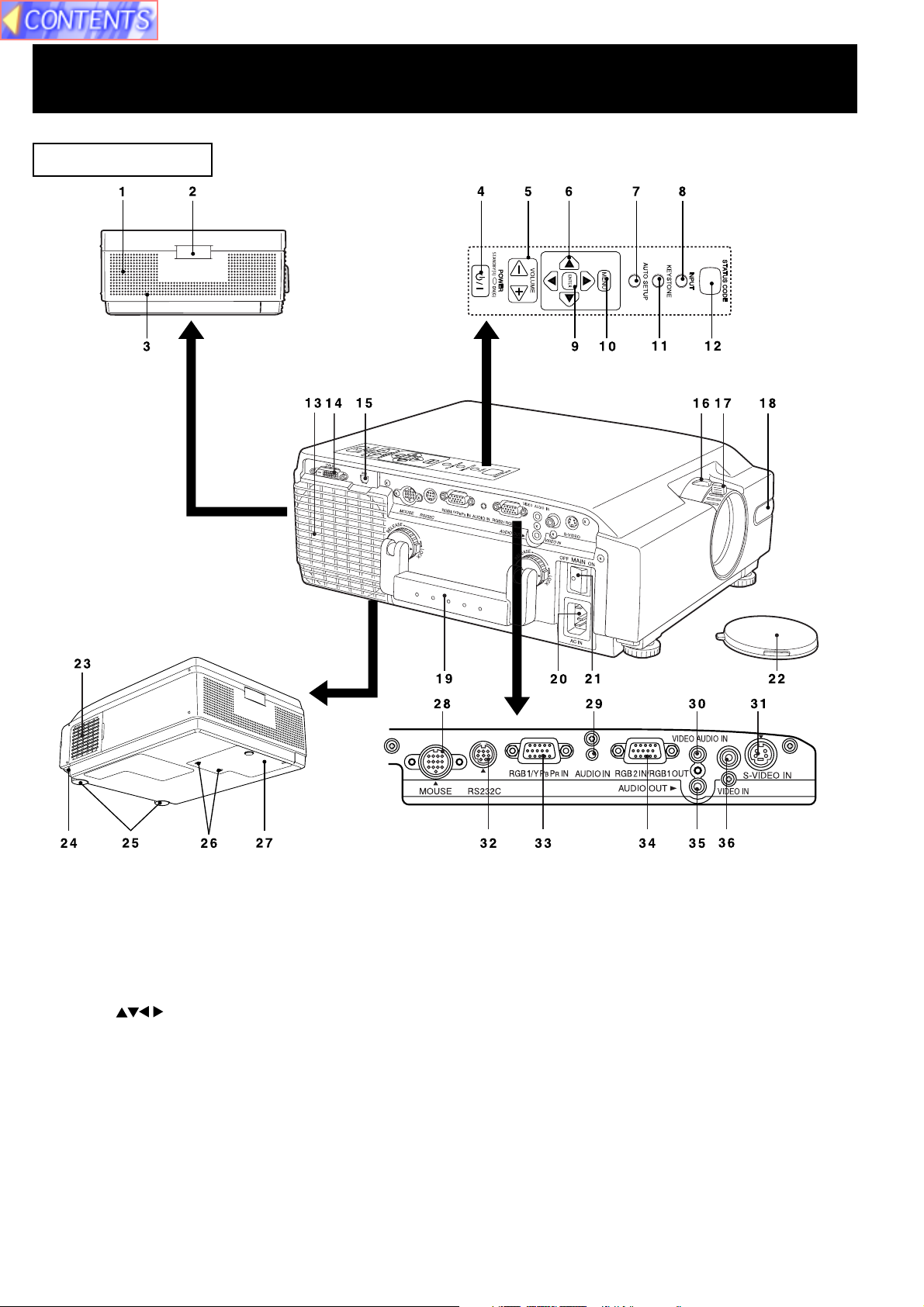
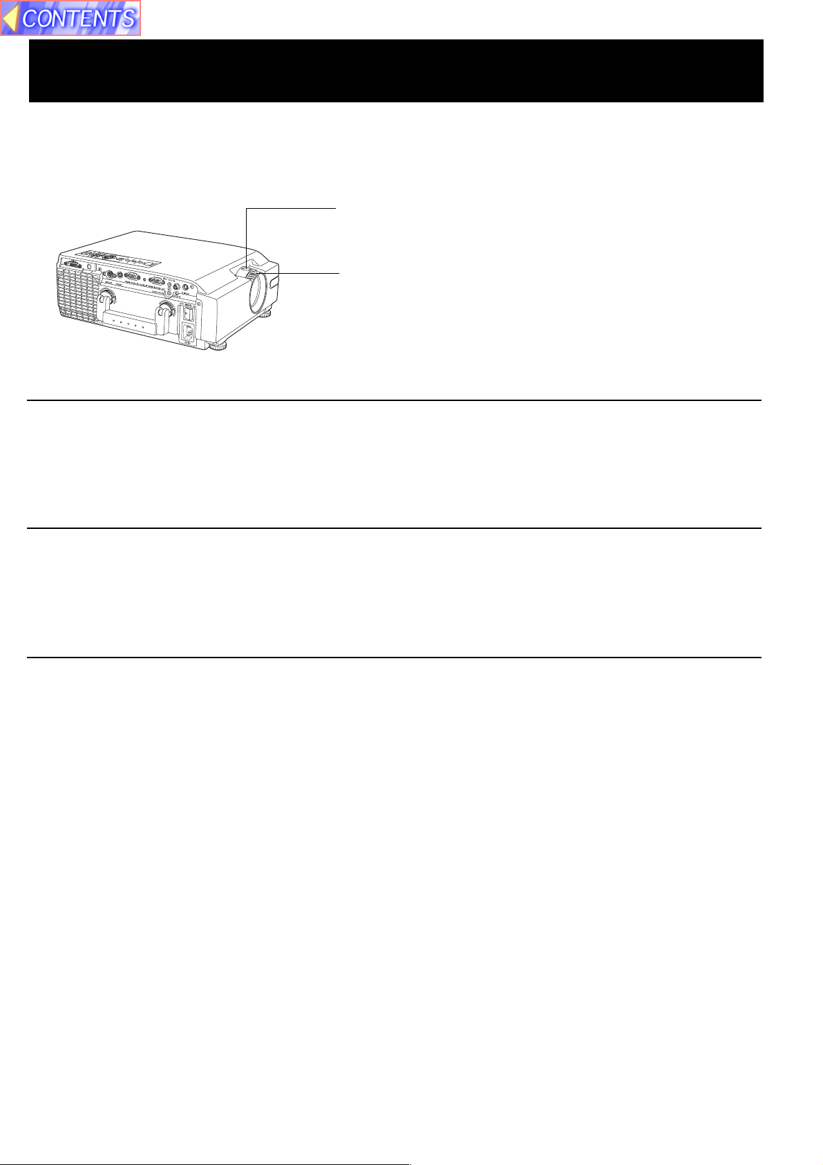
LCD Projector
1 Speaker
2 Remote Control Sensor ........................ See page 11.
3 Security Lock
4 POWER Button/
POWER Indicator STANDBY(R) ON(G) See page 14.
5 VOLUME+/- Buttons ............................. See page 18.
6 Adjust Buttons .................. See pages 19, 22.
7 AUTO SETUP Button ............................ See page 32.
8 INPUT Button......................................... See page 17.
9 ENTER Button ....................................... See page 19.
10 MENU Button ......................................... See page 19.
11 KEYSTONE Button ................................ See page 25.
12 STATUS CODE ...................................... See page 50.
13 Air Outlet Port
14 DVI-D Input Connector
[PT-L759XU only] .................................. See page 42.
15 USB Connector ..................................... See page 48.
16 Zoom Ring ............................................. See page 16.
17 FOCUS Ring .......................................... See page 16.
18 Remote Control Sensor ........................ See page 11.
19 Carrying Handle ..................................See page 49.
20 AC Socket (100 V - 240 V)................... See page 14.
21 Main Power Switch ............................. See page 14.
22 Lens Cap
23 Air Filter ...............................................See page 51.
24 Adjuster Button ...................................See page 15.
25 Adjustable Legs ..................................See page 15.
26 Lamp Cover Screws.................... See pages 53, 54.
27 Lamp Cover ................................. See pages 53, 54.
28 MOUSE Connector ..............................See page 48.
29 RGB Audio Input Connector ......See pages 42, 43.
30 Video Audio Input Connector ...........See page 41.
31 S-Video Input Connector ....................See page 41.
32 RS232C Connector ............................. See page 46.
33 RGB1/YPBPR Input Connector ... See pages 42, 43.
34 RGB2 Input Connector /
RGB1 Output Connector ............ See pages 42, 43.
35 Audio Output Connector .............See pages 41-43.
36 Video Input Connector .......................See page 41.
8
Page 9
Product Information
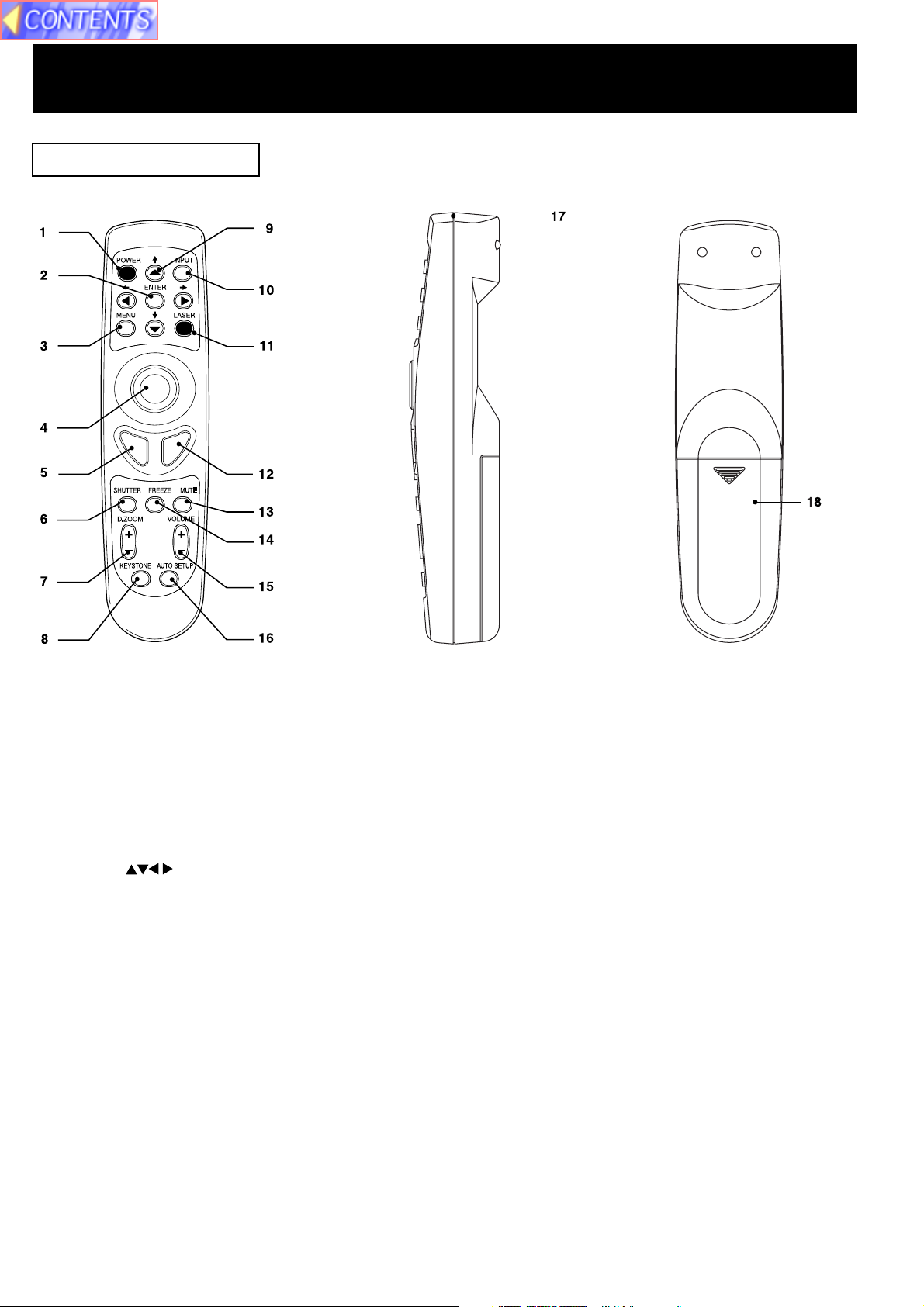
Remote Control Unit
[ Front ] [ Back ]
[ Side ]
1 POWER Button ............................................................................................................................... See page 14.
2 ENTER Button ................................................................................................................................ See page 19.
3 MENU Button .................................................................................................................................. See page 19.
4 Mouse Button ................................................................................................................................. See page 48.
5 Click 1 Button ................................................................................................................................. See page 48.
6 SHUTTER Button ........................................................................................................................... See page 18.
7 D.ZOOM +/-Buttons ....................................................................................................................... See page 38.
8 KEYSTONE Button......................................................................................................................... See page 25.
9 Adjust Buttons ............................................................................................................See pages 19, 22.
10 INPUT Button.................................................................................................................................. See page 17.
11 LASER Button ................................................................................................................................ See page 10.
12 Click 2 Button ................................................................................................................................. See page 48.
13 MUTE Button .................................................................................................................................. See page 18.
14 FREEZE Button .............................................................................................................................. See page 18.
15 VOLUME +/- Buttons ..................................................................................................................... See page 18.
16 AUTO SETUP Button ..................................................................................................................... See page 32.
17 Transmitter ..................................................................................................................................... See page 11.
18 Battery Compartment .................................................................................................................... See page 10.
9
Page 10
Before using the Remote Control Unit
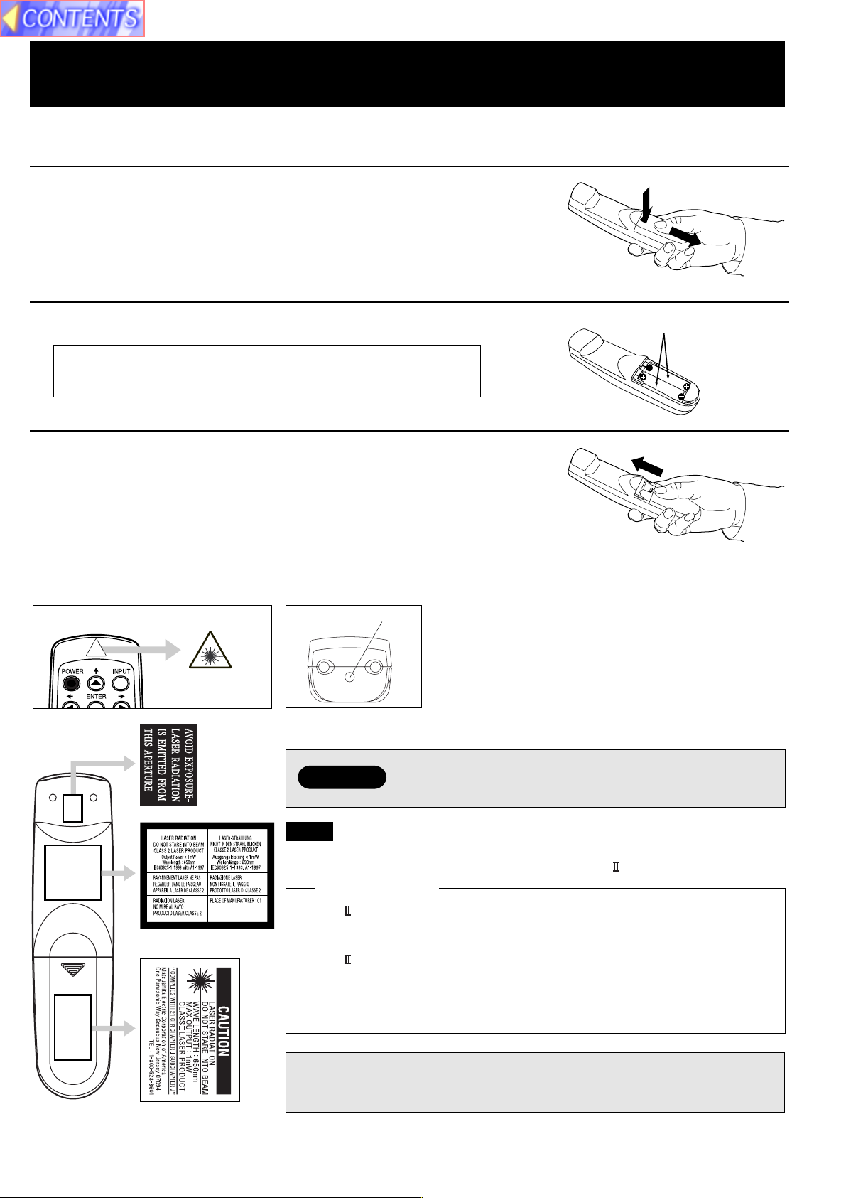
■ Load the 2 “AA” batteries in the Remote Control Unit
1 Slide the lid in the direction of the arrow.
2 Install 2 “AA” batteries as indicated inside the Battery Compartment.
Battery replacement caution
• Do not mix old and new batteries.
Also never mix alkaline with manganese batteries.
3 Replace the lid and snap into place.
■ Using the Laser Pointer on the Remote Control Unit
When the Laser beam is aimed at the screen, the Pointer is displayed on the screen.
Laser transmitter
Press LASER on the remote control to activate Laser.
2 “AA” Batteries (included)
Warning
DO NOT look into the Laser transmitter, or aim the
Laser beam at a person. Shining the Laser beam into
the eyes could result in eye damage.
Note
• This product has the following laser radiation specifications:
Wavelength - 650 nm, Max. Output - 1 mW, Class (Class 2.)
For U.S.A. only
• Class laser products are normally required to be equipped with an
indicator indicating that the laser beam is being emitted. On this product,
the red beam emitted from the laser point functions as this indicator.
• Class laser products are normally required to be equipped with an
emergency stop device such as a shutter to stop the laser immediately. On
this product, instead of such a device, the laser does not stay on unless
the laser button is held in continuously.
CAUTION: Use of controls or adjustments or performance of procedures
other than those specified herein may result in hazardous radiation
exposure.
10
Page 11
Before using the Remote Control Unit
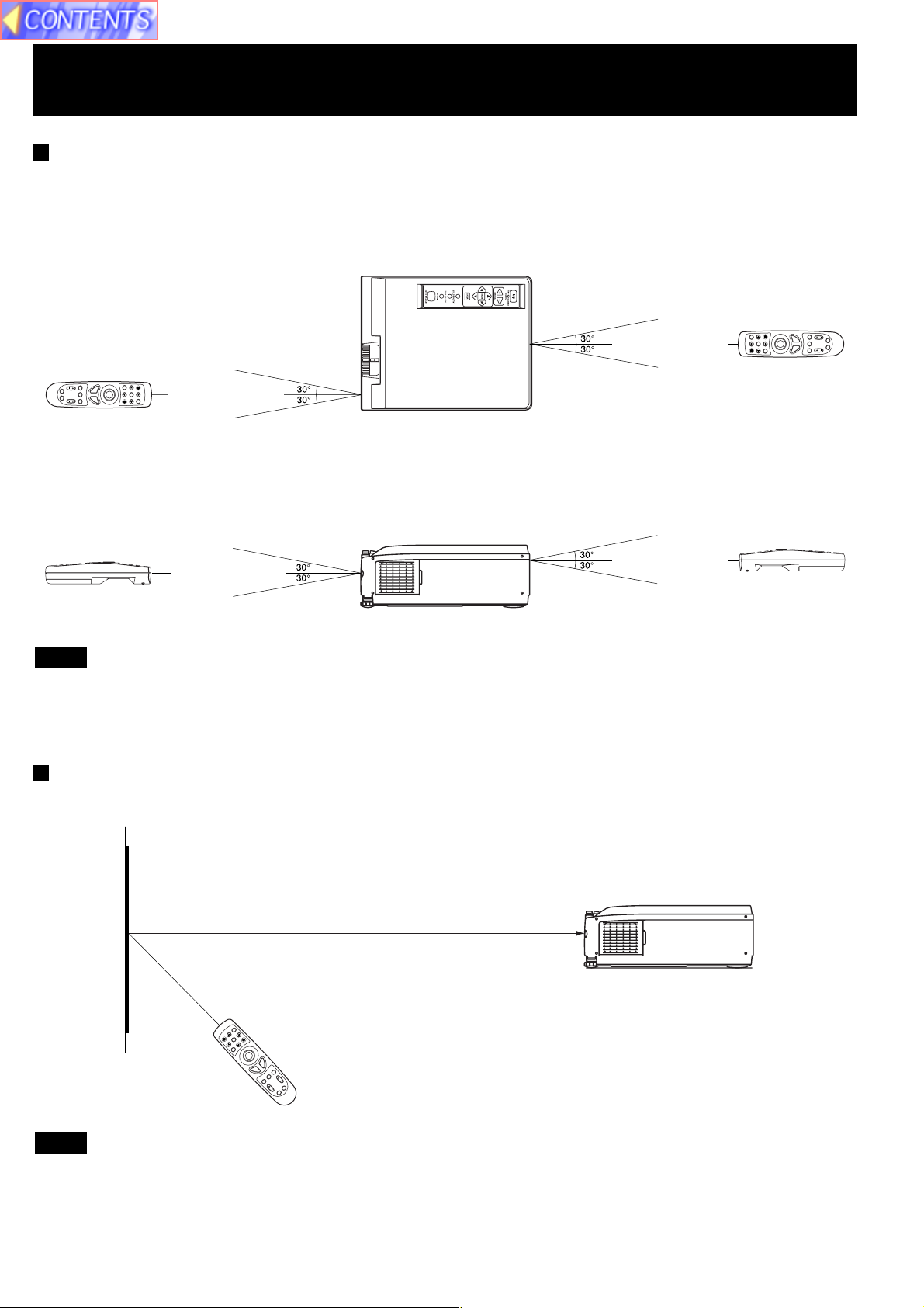
Operating range of the remote control unit
Point the remote control unit toward the remote control signal receptor on the front or the rear of the Projector to operate
the Projector. Refer to the illustration below for the operating range of the remote control unit.
<Top view>
Remote Control Unit Projector Remote Control Unit
(approximately 7 m)
(approximately 7 m)
(When operating from in front)
(When operating from behind)
<Side view>
Remote Control Unit Projector Remote Control Unit
(approximately 7 m)
(When operating from in front)
(approximately 7 m)
(When operating from behind)
Note
• The operating distance is within 7 meters (approximately 23.0 feet) from directly in front of the front or rear remote
control signal receptors.
• If strong light is allowed to shine onto the remote control signal receptor, or if there are any obstacles between the
remote control signal receptor and the remote control unit, correct remote control operation may not be possible.
If facing the remote control unit toward the screen
The Projector can also be operated by pointing the remote control unit toward the screen as shown in the illustration
below.
Screen
Projector
Remote Control Unit
Note
If facing the remote control unit toward the screen to operate the projector, the operating range of the remote control unit
will be limited by the amount of light reflection loss caused by the characteristics of the screen used.
11
Page 12
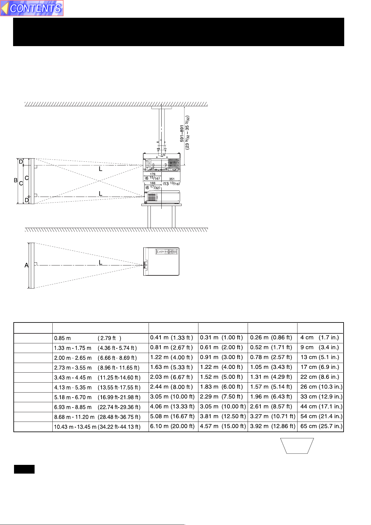
Standard Setting-up Positions
The screen should be positioned so that it is not directly touched by sunlight or room light as this will wash out the colors
of the picture making it hard to see. When possible, close all blinds, curtains, etc. and dim the lights. Also, the LCD
Projector should be at a 90° angle to the screen for the best picture results. To determine the distance for the desired
size, please refer to the LCD Projector/Screen Relationship Chart below.
(By using the digital variable compression feature, you can increase the throw distance. See page 24.)
When installed using the
ET-PK057 ceiling mount
bracket (sold separately).
Unit : mm (inch)
• Your LCD Projector is
equipped with an
image reverse feature.
(See page 22.)
LCD Projector /Screen Relative Position Chart
The picture can be adjusted to the desired size within the range of the zoom lens.
(This chart is based on a reduction ratio of 1 time.) The values in the table are reference values.
Screen size
20 inches
40 inches
60 inches
80 inches
100 inches
120 inches
150 inches
200 inches
250 inches
300 inches
• If the LCD Projector and the screen are not properly placed, the picture will be distorted
producing a keystoned image as shown at right.
Throw distance (L) Measure (A) Measure (B)
Measure (C) Measure (D)
Keystoned Image
Note
• Using the Optional Wide Conversion lens (ET-LEC059), you can shorten the above throw distances by 0.8 times.
12
Page 13
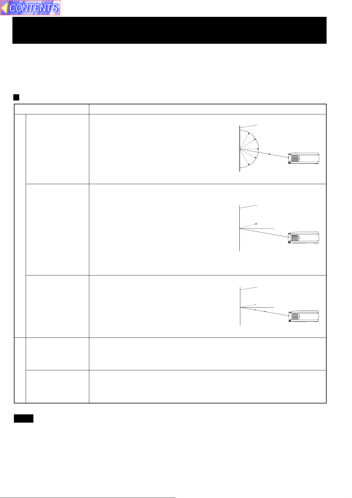
Screen Requirements
This Projector is used to project the image onto flat screens. However, the brightness and viewable range will vary
depending on which type of screen is used.
When selecting a screen, check the characteristics of the screen to ensure that it is suitable for the intended place of
use.
Screen characteristics (reference)
Screen type
White screen
Silver screen
Reflective screens
Screen characteristics
This type of screen can be seen from anywhere,
so there are no limits on the viewing position.
However, the surrounding walls should be
darkened as in a movie theatre, otherwise a
clear picture cannot be obtained.
This type of screen gives a picture which is 2-4
times brighter than a white screen. A variety of
types are available from different manufacturers,
and each type has different brightness
characteristics. Some also have restrictions on
the possible range of viewing positions.
* Care should be taken with screens that have
a high gain, as these types of screen can
cause color distortion at the left and right
edges.
* This type of screen is recommended when the
Projector is suspended from the ceiling.
White screen
Silver screen
Maximum brightness
Beaded screen
Flexible
translucent screen
Rigid-type
translucent screen
Translucent screens
This type of screen is similar to the silver
screen, except that no color distortion occurs
at the left and right edges. Moreover, most of
the light is reflected at the same angle as the
angle of incidence.
* This type of screen is recommended when
the Projector is placed on the floor.
This type of screen is made of PVC (polyvinyl chloride).
It has the same characteristics as silver screens, but sometimes it can have hot
spots.
This type of screen is made of acrylic plastic.
It is extremely durable and has excellent optical characteristics. It performs in the
same way as silver screens.
Beaded screen
Brightness decline
Maximum
brightness
Note
• A Polarized screen can not be use for this LCD Projector, because its polarizing effect will add to the polarization
already designed into the Projector (to increase its efficiency). The resulting image will not appear in its true
color.
13
Page 14

Turning the power on and off
If the MAIN POWER switch on the LCD Projector is turned off while the cooling fan is still operating, the operating life of
the projector lamp will be shortened. Be sure to follow the procedures given below when turning the LCD Projector
power supply on and off.
POWER Button/
POWER Indicator
STANDBY(R) ON(G) MAIN POWER Switch
(LCD Projector)
• Turning on the power
MAIN
1
2
(LCD Projector)
OFF ON
or
(Remote Control
Unit)
Press the
MAIN POWER
switch
Press the
POWER button
Press the MAIN POWER switch on the LCD Projector to ON.
The power indicator will illuminate red and the Projector will switch
to standby mode.
Press POWER button on the LCD Projector or remote control.
The power indicator will illuminate solid green and a picture will be
projected onto the screen.
Note
The LCD Projector cannot be turned on for 60 seconds after
turning it off.
(Remote Control Unit)
POWER Button
• Turning off the power
1
Press the
POWER button
or
(LCD Projector)
(Remote Control
Unit)
2 Wait for the cooling fan to stop.
3
Press the
MAIN POWER
switch
Press POWER button on the LCD Projector or remote control.
“Please press POWER button again to power off.” is displayed on
the screen, and then press POWER button again.
The power indicator will illuminate flashing red and the Projector
will switch to standby mode.
Wait for a while (approximately 2 minutes) until the power indicator
will illuminate solid red.
Press the MAIN POWER switch on the LCD Projector to OFF.
The power indicator will switch off and the power supply will be
turned off.
Note
• Insert Power Cord into LCD Projector AC socket and connect to properly grounded wall outlet.
• If the power is turned off using the POWER button, the cooling fan will continue to operate while the inside of the
Projector is still at a high temperature. Do not turn the MAIN POWER switch to the OFF position, disconnect the power
cord plug from the wall socket or shut off the mains power supply until the cooling fan stops operating.
• If the MAIN POWER switch has not been turned off, the Projector will still draw approximately 20 W of power, even
when the POWER button has been turned off and the fan has stopped.
• To prevent the Lamp, when the power is turned off, the Lamp lights for just a moment as the cooling fan stops.
14
Page 15
Adjusting the LCD Projector Projection Angle
Adjusting the LCD Projection angle of the LCD Projector. When the projector is in the horizontal position, keystone
correction is unnecessary and a correct image can be viewed.
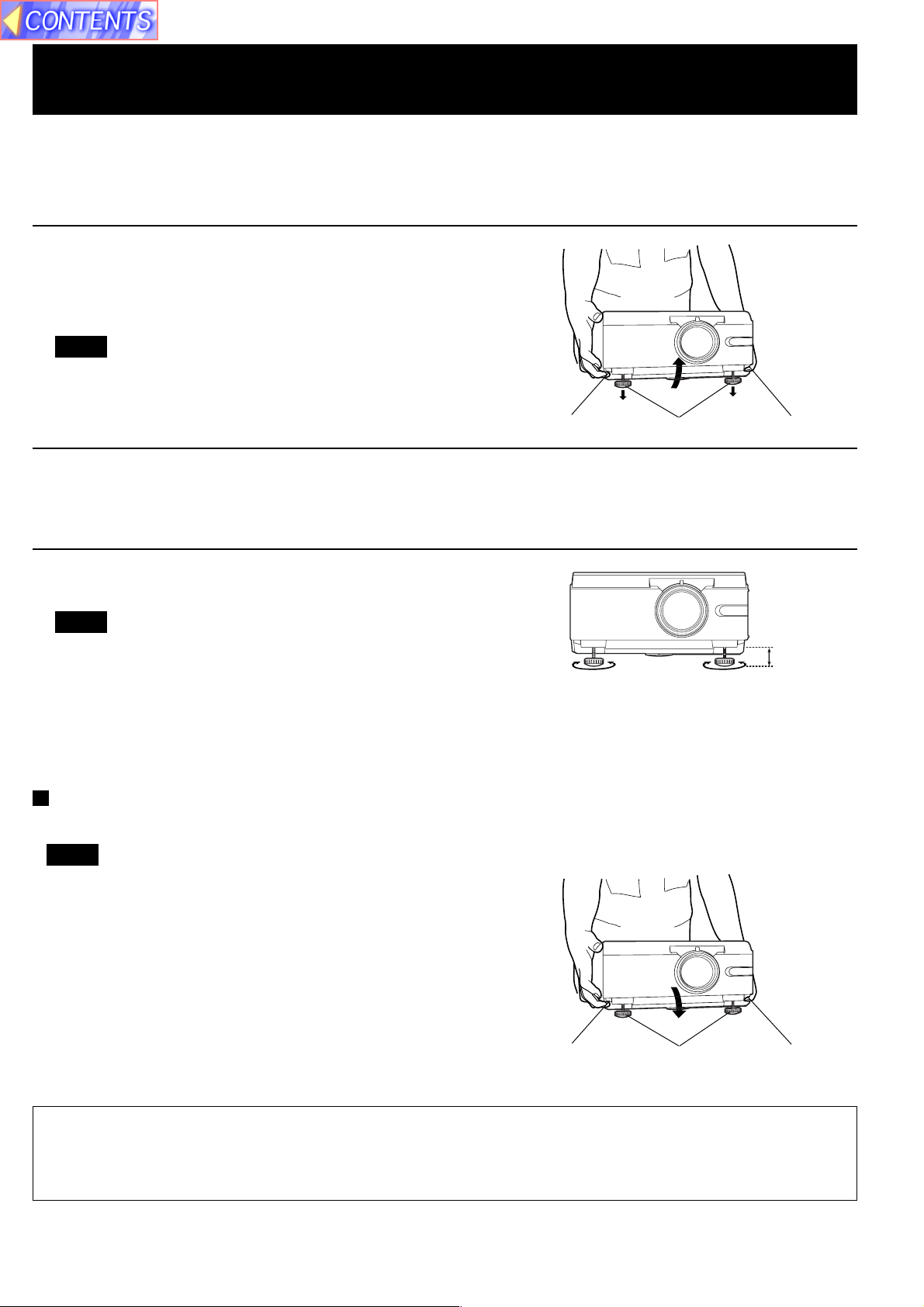
• Adjustment procedure
1 Lift the front of the LCD Projector to the desired angle. While
holding it in place, press the 2 adjuster buttons located under
the right and left sides of the projector. When the buttons are
pressed, the left and right adjustable legs will drop down until
they reach the setting-up surface.
Note
• Do not release the buttons until both legs have reached the
setting-up surface.
Adjuster button Adjustable legs
Adjuster button
2 Release the adjuster buttons. (The adjustable legs will lock as
soon as the buttons are released.)
3 Turn the adjustable legs by hand in either direction to make
fine adjustments.
Note
• The legs can be extended by up to 52 mm. If you try to
extend them any further than this, they will merely spin
freely.
Retracting the adjustable legs
After lifting the front of the Projector slightly, press and hold the adjuster buttons and then gently lower the Projector.
Note
• Be sure to support the Projector firmly while pressing the
adjuster buttons. If the adjuster buttons are pressed
without supporting the Projector, the adjustable legs will
suddenly unlock and the Projector will fall down, which
could catch your fingers and damage the Projector.
52 mm
Adjuster button Adjustable legs Adjuster button
Caution: When you set up the LCD Projector
• Do not place it in humid or dusty places, or places where the air is sooty or full of cigarette smoke. If the lens, mirror,
or other optical components become dirty, the picture will blur or darken, making viewing difficult.
• Do not expose to extreme heat or cold. Operating temperature: 0 °C – 40 °C (32 °F – 104 °F)
15
Page 16
Adjusting the Lens
If the LCD Projector is not set up so that it is horizontal, it will not be possible to obtain a distortion-free picture. Turn the
adjusters in either direction to make fine adjustments to the level of the Projector so that the Projector is perfectly
horizontal.
ZOOM Ring
FOCUS Ring
• Adjustment procedure
1 Turn the ZOOM Ring to adjust the size of the picture.
• When facing the rear of the projector, turn the ring to the right for a larger
picture, or to the left for a smaller picture.
2 Turn the FOCUS Ring to adjust the focus of the picture.
• Turn the ring to the right or left until the picture is at the optimum focus.
3 Turn the ZOOM Ring again to adjust the size of the picture.
• When you turn the FOCUS Ring, the size of the picture changes.
16
Page 17
Changing the input signal
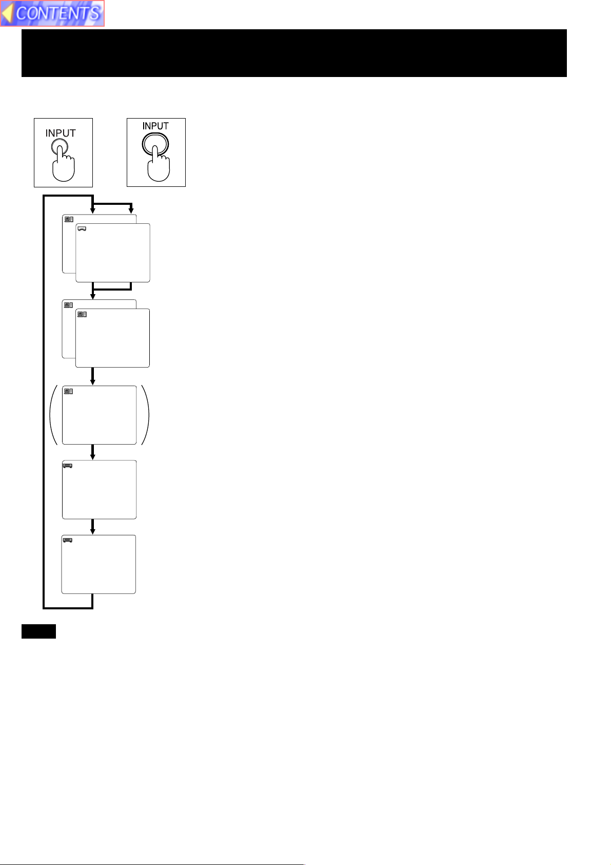
(LCD Projector) (Remote Control
Unit)
Press the INPUT button
The input source for picture signals and the corresponding audio signals can
or
1BGR
PY
P
R
B
be changed by pressing the INPUT buttons on the Projector operating panel
or on the remote control.
The signal from the source which is connected to the RGB1/YPBPR
connector is projected.
This terminal accepts input of RGB input signals from a personal computer
and DTV Format signals (RGB, YPBPR) from a DVD or a digital broadcast.
No monitor or Projector can automatically decide whether a Component
signal is the RGB-type or the YPBPR-type. So, you will have to select either
RGB or YPBPR manually.
2BGR
TUO1BGR 2BGR
The signal from the source which is connected to the RGB 2 IN/ RGB 1 OUT
terminal is projected.
This terminal accepts an RGB signal from a PC in addition to a DTV format
signal (RGB) from a digital broadcast, DVD, etc. And, by setting the terminal
to OUT, the signal input to the RGB1/YPBPR connector can be output. At that
time, the projected screen will go to blue back. (See page 40.)
D-IVD
[PT-L759XU
only]
OEDIV
OEDIV-S
The signal input to the DVI-D (Digital Visual Interface)input terminal is
projected. The video signal from the PC is input to the LCD Projector as a
digital signal, you can enjoy superior picture quality. [PT-L759XU only]
The signal from the source which is connected to the VIDEO IN connector is
projected.
The signal from the source which is connected to the S-VIDEO IN connector
is projected.
Note
• To turn off the input signal on-screen display, please see “Turning off the input signal display” on page 34.
• There is only one audio system circuit provided for the VIDEO AUDIO IN terminals for S-VIDEO and VIDEO signals.
Because of this, if using both S-VIDEO signals and VIDEO signals, it will be necessary to change over the connectors.
• There is only one audio system circuit provided for the AUDIO IN terminals for RGB1/YPBPR, RGB2,
DVI-D [PT-L759XU only] signals. Because of this, if using both RGB1/YPBPR,RGB2 signals and DVI-D signals, it will
be necessary to change over the connectors.
• The LCD Projector is shipped from the factory with the S-VIDEO/VIDEO signal selection function set to “AUTO.” If the
correct picture is not projected when VIDEO signal is input and it is necessary to change the input to match the input
signal, refer to “S-VIDEO/VIDEO Signal Format Selection” on page 28.
• Please refer to page 39 to change the setting if you change the signal input to the RGB1/YPBPR connector.
• When RGB signal is input, please input the registered signals found on page 26.
• Please refer to page 40 to change the setting if you change the signal select to the RGB2 IN/RGB1 OUT connector.
• When projecting via the DVI-D input, first connect the LCD Projector to your PC using the DVI cable, and then turn the
PC on.
17
Page 18
Basic LCD Projector Operation
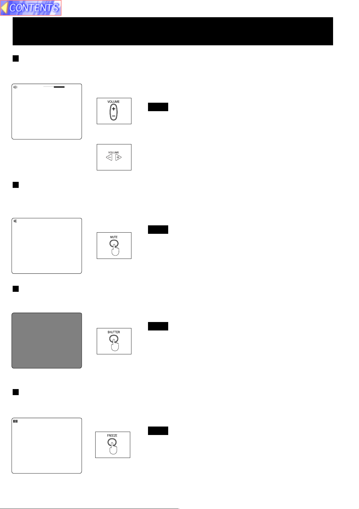
Adjusting the Volume
The volume can be adjusted using the VOLUME +/- buttons on the LCD Projector or remote control.
emuloV
42+
(Remote Control
Unit)
• Press VOLUME + button to turn the volume high.
• Press VOLUME - button to turn the volume low.
Note
• The “Volume” will remain displayed on the screen for approximately
5 seconds.
or
(LCD Projector)
Turning off the sound
If the MUTE button on the remote control is pressed, “Mute” will be displayed on the screen as shown in the illustration
below and the sound will be muted. If the MUTE button is pressed again, the normal sound volume will be restored.
etuM
(Remote Control
Unit)
Note
• If the Power supply is turned off or either of the VOLUME +/buttons is pressed, the mute setting will be cancelled.
Turning off the Picture and Sound at the same time
When SHUTTER button is pressed on the remote control the picture and sound turns off and the screen goes black,
Press SHUTTER button again to resume picture and sound.
(Remote Control
Unit)
Note
• When the screen goes black, the picture will not be shown on
the screen. However, the picture continues to be sent from the
Personal Computer or video source.
Black screen
Freezing the picture
Projection can be switched between a frozen (still) picture and a moving picture each time when the FREEZE button on
the remote control is pressed. Press FREEZE button again to resume motion.
ezeerF
(Remote Control
Unit)
Note
• The sound is muted while the picture frozen.
18
Page 19
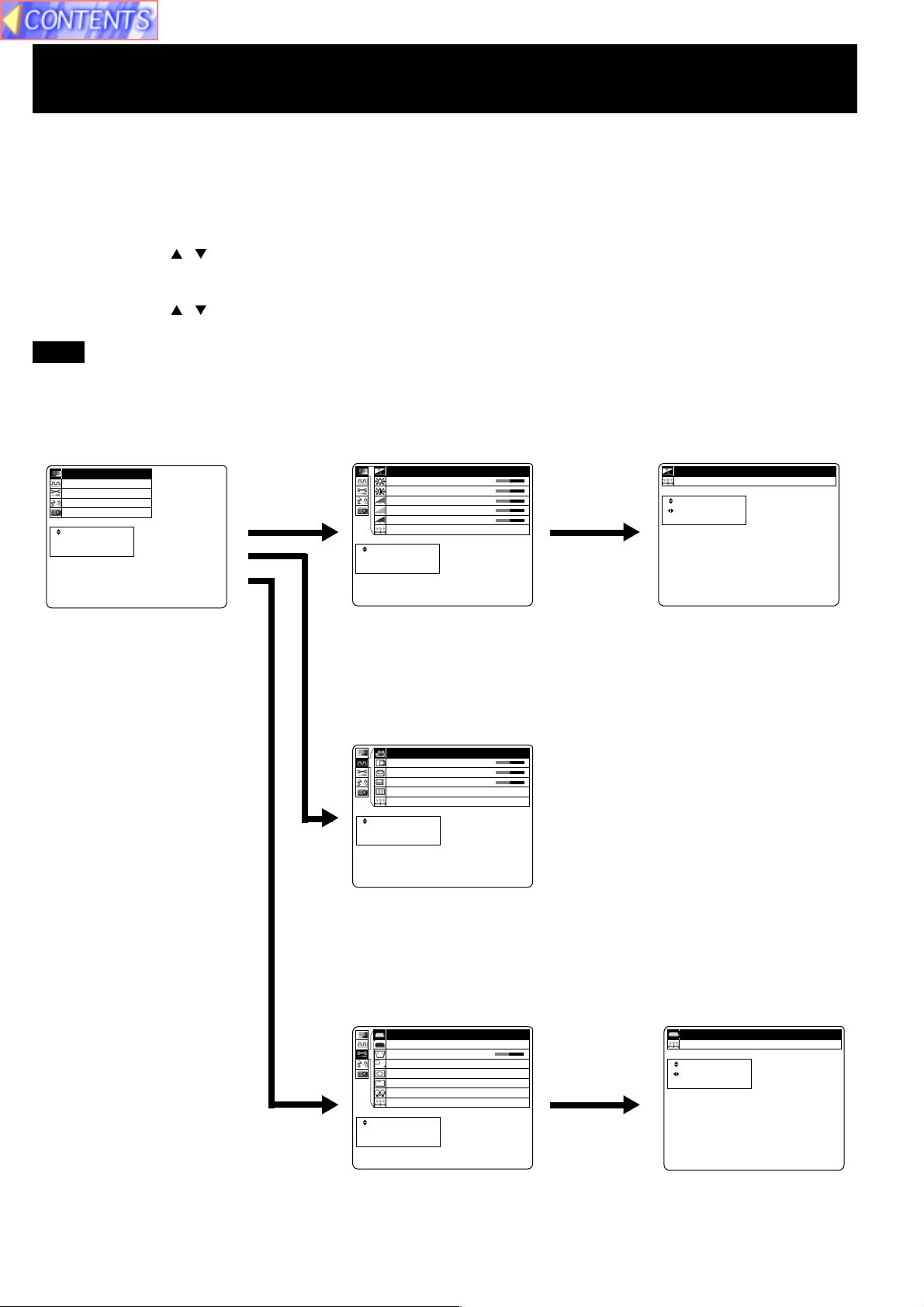
Menu operation guide
This section explains how to reach the desired selection or setting screens from the MENU screen. Refer to the page
indicated for further details on each screen item.
1 Press the MENU button.
(The Main MENU screen will be displayed.)
2 Use the arrow ( , ) buttons to select an item, and then press the ENTER button.
(The Second MENU screen will be displayed.)
3 Use the arrow ( , ) buttons to select an item, and then press the ENTER button.
(The Adjustment MENU screen will be displayed.)
Note
• Press MENU to remove the setup screen and menu.
<Main MENU> <Second MENU> <Adjustment MENU>
Picture
cimany
D
ytilsa
u
Q
e
g
a
m
P
n
y
S
n
u
F
n
a
L
f
n
I
E
T
N
E
U
N
E
M
a
z
i
n
o
r
h
c
n
o
i
t
c
e
g
a
u
g
n
o
i
t
a
m
r
o
t
c
e
l
e
S
:
R
r
e
t
n
E
:
e
p
a
c
s
E
:
n o i t
e
r
u
t
c
i
I
B
C
R
G
B
R
R
E
T
N
E
U
N
E
M
s
e
n
t
h
g
i
r
t
s
a
r
t
n
o
l
e
v
e
L
l
e
v
e
L
l
e
v
e
L
t
e
s
e
t
c
e
l
e
S
:
r
e
t
n
E
:
e
p
a
c
s
E
:
0
1
+
0
1
+
0
1
+
0
1
+
0
1
+
teseR
t
c
e
l
e
S
:
U
N
E
M
t
s
u
j
d
A
:
e
p
a
c
s
E
:
cimanyD ytilauQ egamI
When RGB signal is being
projected.
Used to picture adjustments.
Synchronization
A
P
H
P
V
t
o
D
a
h
P
s
e
R
S
:
R
E
:
E
T
N
E
E
:
U
N
E
M
n
o
i
t
i
s
o
n
o
i
t
i
s
o
k
c
o
l
C
e
s
t
e
t
c
e
l
e
r
e
t
n
e
p
a
c
s
p
u
t
e
S
o
t
u
0
1
+
0
1
+
0
1
+
01
Used to adjust the horizontal and vertical position of the picture and to
adjust other properties such as the size.
Function
P
Y
/
1
B
G
R
P
R
B
U
O
1
B
G
R
/
N
I
2
B
G
R
n
o
t
s
y
e
K
t
c
e
j
o
r
P
s
e
r
p
m
o
C
e
r
c
S
n
O
a
L
o
t
u
A
t
e
s
e
R
c
e
l
e
S
:
R
T
N
E
N
E
M
r
e
t
n
E
:
E
p
a
c
s
E
:
U
e
e
d
o
M
n
o
i
n
o
i
s
l
p
s
i
D
n
e
f
f
O
p
m
t
e
1
B
G
R
T
U
O
T
0
1
+
1
6
.
0
x
N
O
y
a
S
E
Y
E
M
PY/1BGR
P
R
B
teseR
c
e
l
e
S
:
s
u
j
d
A
:
p
a
c
s
E
:
U
N
t
t
e
1B
GR
Used to adjust and change the settings of the various functions
available on the projector.
19
Page 20
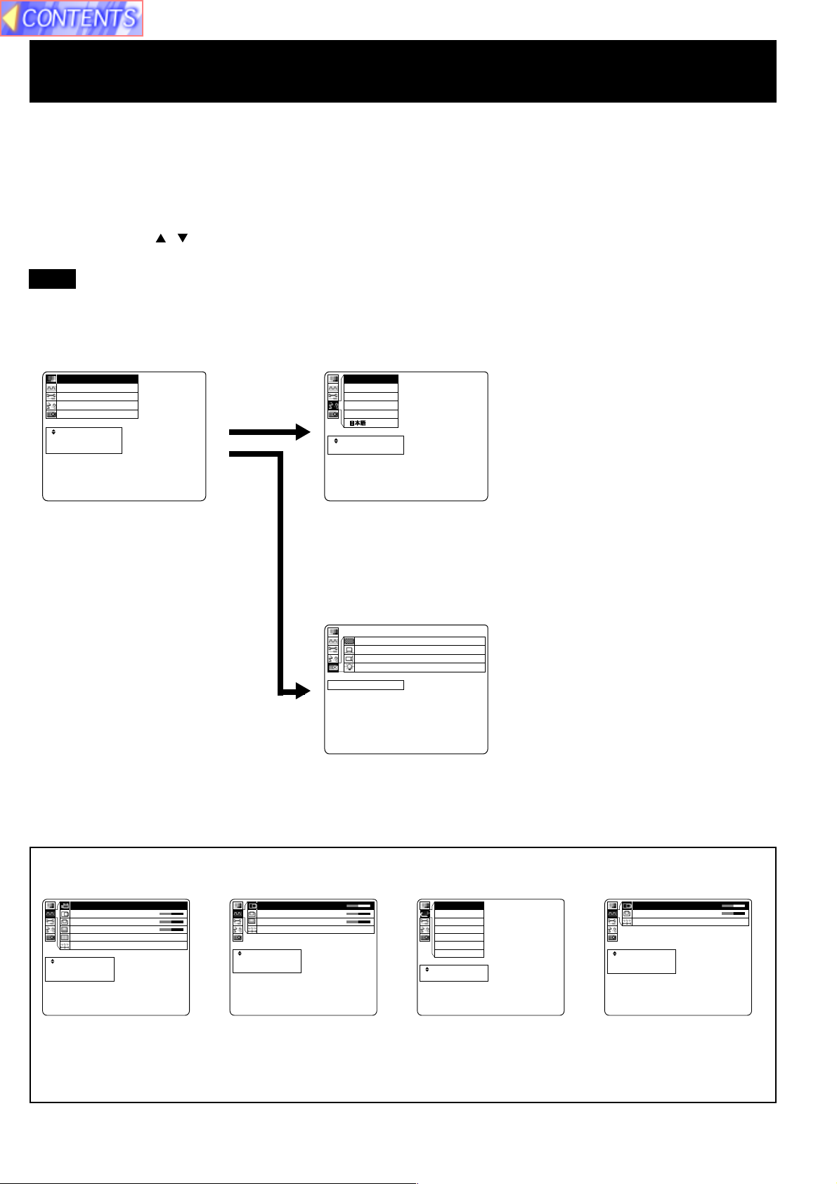
Menu operation guide
This section explains how to reach the desired selection or setting screens from the MENU screen. Refer to the page
indicated for further details on each screen item.
1 Press the MENU button.
(The Main MENU screen will be displayed.)
2 Use the arrow ( , ) buttons to select an item, and then press the ENTER button.
(The Second MENU screen will be displayed.)
Note
• Press MENU to remove the setup screen and menu.
<Main MENU> <Second MENU>
Language
n o i t
e
r
u
t
c
i
P
n
y
S
n
u
F
n
a
L
f
n
I
E
T
N
E
U
N
E
M
a
z
i
n
o
r
h
c
n
o
i
t
c
e
g
a
u
g
n
o
i
t
a
m
r
o
t
c
e
l
e
S
:
R
r
e
t
n
E
:
e
p
a
c
s
E
:
l
g
n
E
t
u
e
D
n
a
r
F
a
p
s
E
l
a
t
I
M
h
s
i
h
c
s
s
i
a
ç
l
o
ñ
o
n
a
i
tecpealcesSE:: U N E
When RGB signal is being
Used to switch the on-screen display language.
projected.
Information
N
r
F
H
r
F
V
p
m
a
L
y
c
n
e
u
q
e
y
c
n
e
u
q
e
e
m
i
t
n
u
R
epacsE:UNEM
z
H
K
9
.
z
H
5
8
h
0
1
8
6
7
x
482601
s
t
o
D
f
o
.
o
Use to display information about the input signal, lamp run time, etc.
The displayed items on the screen differ according to the input signal.
p
u
t
e
S
o
t
u
A
H
V
o
D
h
P
e
R
:
R
:
E
T
N
E
:
U
N
E
M
n
o
i
t
i
s
o
P
n
o
i
t
i
s
o
P
k
c
o
l
C
t
e
s
a
t
e
s
t
c
e
l
e
S
r
e
t
n
E
e
p
a
c
s
E
0
1
+
0
1
+
0
1
+
01
H
V
D
R
R
E
T
N
E
U
N
E
M
nno
i
t
i
s
o
P
o
i
t
i
s
o
P
k
c
o
l
C
t
o
t
e
s
e
t
c
e
l
e
S
:
r
e
t
n
E
:
e
p
a
c
s
E
:
0
1
+
0
1
+
0
1
+
M
O
T
U
A
C
S
T
N
3
4
.
4
C
S
T
N
L
A
P
M
-
L
A
P
N
-
L
A
P
M
A
C
E
S
tecpealcesSE:: U N E
H
V
R
R
E
T
N
E
U
N
E
M
n
ooiittiis
o
P
n
s
o
P
t
e
s
e
t
c
e
l
e
S
:
r
e
t
n
E
:
e
p
a
c
s
E
:
0
1
+
0
1
+
0
1
+
When RGB signal is being
projected.
When YPBPR signal is being
projected.
When Video/S-Video signal
is being projected.
When DVI-D signal is
being projected. [PTL759XU only]
20
Page 21
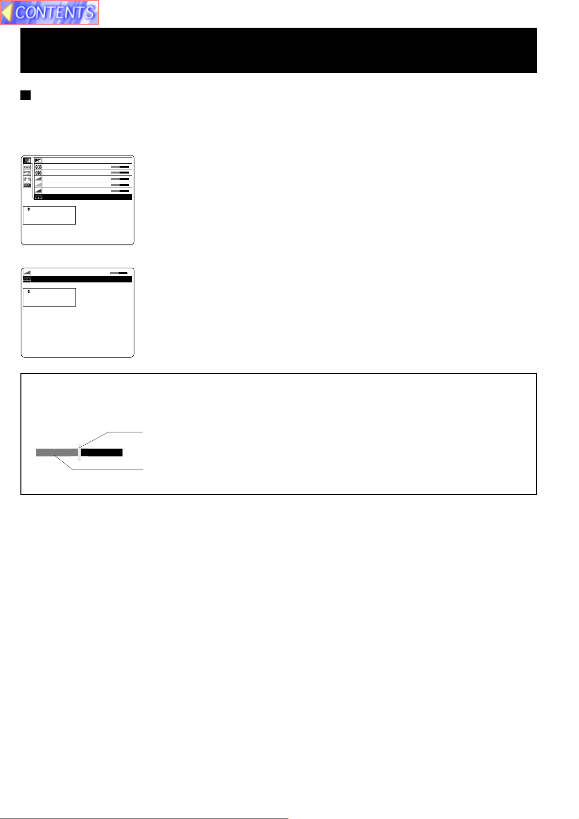
Menu operation guide
Returning adjustment values to the factory default settings (standard values)
If “Reset” is selected while the “Second MENU” or an “Adjustment MENU” is displayed, the setting can be
returned to the factory default setting.
• During a second menu screen is displayed, chose the “Reset” and then press the ENTER button.
All items displayed in the second menu return to the
cimany
D
ytilsa
u
Q
e
g
a
m
I
B
C
R
G
B
R
R
E
T
N
E
U
N
E
M
s
e
n
t
h
g
i
r
t
s
a
r
t
n
o
l
e
v
e
L
l
e
v
e
L
l
e
v
e
L
t
e
s
e
t
c
e
l
e
S
:
r
e
t
n
E
:
e
p
a
c
s
E
:
• During an individual adjustment screen is displayed, chose the “Reset” and then press the ENTER button.
leveLR
teseR
t
c
e
l
e
S
:
R
E
T
N
E
U
N
E
M
r
e
t
n
E
:
e
p
a
c
s
E
:
0
1
+
0
1
+
0
1
+
0
1
+
0
1
+
01+
factory settings.
Only items selected in the second menu return to the
factory settings.
Bar Scale display
The bar scale mark indicates the factory standard value. The mark is only displayed when a factory standard value
was assigned.
This bar shows the factory standard value.
This bar shows the current value adjustment.
21
Page 22

Setting-up Positions and Changing the Projection Mode
The projection mode used by the Projector can be changed in accordance with the setting-up position. Including ceiling
mounting, you may select from four direction types. At the time of shipment from the factory, the Projector is set to the
No.1 “DESK/FRONT” projection mode, but this can be changed if required.
The procedure and on-screen display as shown below are based on RGB as the input signal from a personal computer.
(See page 17.)
• Setting procedure
n o i t
e
r
u
t
c
i
1 Press MENU to display the menu.
2 Press or to select “Function”, and then ENTER to display the
screen.
3 Press or to select “Projection Mode”, and then ENTER to
display the screen.
P
n
y
S
n
u
F
n
a
L
f
n
I
E
T
N
E
U
N
E
M
E
T
N
E
U
N
E
M
a
z
i
n
o
r
h
c
n
o
i
t
c
e
g
a
u
g
n
o
i
t
a
m
r
o
t
c
e
l
e
S
:
R
r
e
t
n
E
:
e
p
a
c
s
E
:
P
Y
/
1
B
G
R
P
R
B
U
O
1
B
G
R
/
N
I
2
B
G
R
n
o
t
s
y
e
K
t
c
e
j
o
r
P
s
e
r
p
m
o
C
e
r
c
S
n
O
a
L
o
t
u
A
t
e
s
e
R
c
e
l
e
S
:
R
r
e
t
n
E
:
p
a
c
s
E
:
e
e
d
o
M
n
o
i
n
o
i
s
l
p
s
i
D
n
e
f
f
O
p
m
t
e
1
B
G
R
T
U
O
T
0
1
+
1
6
.
0
x
N
O
y
a
S
E
Y
4 Press or to select projecting mode from 1 to 4.
• Select 1 ..... DESK/FRONT (Factory setting)
• Select 2 ..... DESK/REAR (Right and Left displays in reverse)
• Select 3 ..... CEILING/REAR (Up and Down displays in reverse)
• Select 4 ..... CEILING/FRONT (Up and Down/Right and Left reverse display.)
Note
• Press MENU to remove the setup screen and menu.
• When reset is selected, adjustment values return to their factory default settings.
Select 1 ......DESK/FRONT Select 2 ......DESK/REAR
(Factory setting)
Select 3 ......CEILING/REAR Select 4 ......CEILING/FRONT
(Right and Left displays in reverse)
teseR
t
c
e
l
e
S
:
U
N
E
M
t
s
u
j
d
A
:
e
p
a
c
s
E
:
1 edoM noitcejorP
(Up and Down displays in reverse) (Up and Down/Right and Left reverse display)
Note
• If the lettering on the screen is projected backwards or upside down, it is because the wrong mode has been selected.
22
Page 23

Setting the Screen Type
t
e
c
r
p
e
e
a
l
t
c
e
n
s
S
E
E
:
:
:
R
E
U
T
N
N
E
E
M
m
e
n
t
o
s
i
y
n
e
t
e
S
o
g
a
r
i
a
m
u
o
t
u
r
t
e
c
g
o
c
d
n
n
f
i
i
u
a
n
P
V
F
L
I
t
t
e
c
s
p
e
u
a
l
j
c
e
d
s
S
A
E
:
:
:
U
N
E
M
teseR
3:4neercS
1
T
1
3
F
6
N
S
B
U
:
F
.
O
E
G
O
4
O
0
Y
R
x
0
1
y
T
+
a
U
e
l
O
d
p
o
s
f
1
M
i
f
B
n
D
O
G
n
o
R
o
i
n
p
/
e
i
s
e
m
P
N
n
t
s
e
a
Y
I
o
c
n
e
r
L
/
t
e
e
r
c
t
1
2
s
j
e
9
p
S
o
e
B
B
y
o
r
:
m
t
s
G
G
e
r
c
6
o
n
u
e
R
R
K
P
S
1
C
O
A
R
R
P
B
t
e
c
r
p
e
e
a
l
t
c
e
n
s
S
E
E
:
:
:
R
E
U
T
N
N
E
E
M
This LCD Projector is compatible with wide screen (16:9 ratio). If a wide screen is used and you set the screen type to
16:9 in order to project a wide (16:9) picture to fill the entire screen, pictures are correctly projected within the screen
when projecting older (normal) 4:3 ratio pictures.
Please follow the instructions below to set the screen type.
The procedure and on-screen displays below are based on S-Video/Video as the input signal. (See page 17.)
• Setting procedure
1 Press MENU to display the menu.
2 Press or to select “Function”, and then ENTER to display the
screen.
3 Press or to select “Screen”, and then ENTER to display the
screen.
4 Press or to change the screen type.
• The 4:3 type screen is set at the factory.
Note
• Press MENU to remove the setup screen and menu.
• When reset is selected, adjustment values return to their factory default settings.
16:9 (Wide) Function OFF 16:9 (Wide) Function ON
Screen
4:3 Type
Screen
Projected pictures
(4:3)
Screen
16:9 Type
Screen
Projected pictures
(4:3)
Screen
Projected pictures
(16:9)
Screen
Projected pictures
(16:9)
Note
Note
• Please refer to “Changing to 16:9 (wide) screen format” on page 35 if you change to the wide 16:9 (wide) screen and
project pictures.
23
Page 24

Digital Variable Compression
The projected size of the input image can be reduced to the level you select. With this feature, you can match the input
resolution. When projecting a signal within 1 024 X 768, you can reduce the image and adjust it to the original image
quality. This will allow you to increase the throw distance.
The procedure and on-screen display as shown below are based on RGB as the input signal from a personal computer.
(See page 17.)
• Adjustment procedure
n o i t
e
r
u
t
c
i
1 Press MENU to display the menu.
2 Press or to select “Function”, and then ENTER to display the
screen.
3 Press or to select “Compression”, and then ENTER to display
the screen.
P
n
y
S
n
u
F
n
a
L
f
n
I
E
T
N
E
U
N
E
M
E
T
N
E
U
N
E
M
a
z
i
n
o
r
h
c
n
o
i
t
c
e
g
a
u
g
n
o
i
t
a
m
r
o
t
c
e
l
e
S
:
R
r
e
t
n
E
:
e
p
a
c
s
E
:
P
Y
/
1
B
G
R
P
R
B
U
O
1
B
G
R
/
N
I
2
B
G
R
o
t
s
y
e
K
c
e
j
o
r
P
e
r
p
m
o
C
r
c
S
n
O
L
o
t
u
A
t
e
s
e
R
e
l
e
S
:
R
e
t
n
E
:
a
c
s
E
:
e
n
t
s
e
a
c
r
p
e
d
o
M
n
o
i
n
o
i
s
p
s
i
D
n
e
f
f
O
p
m
t
e
1
B
G
R
T
U
O
T
0
1
+
1
6
.
0
x
N
O
y
a
l
S
E
Y
4 Press or to adjust the compression.
• Image can be reduced up to 0.6.
• When the number of dots of projected image corresponds with
832 X 624, 800 X 600, or 640 X 480, the image dimensions are displayed.
• When the input signal dot number corresponds with the projected image, the
image dimensions are displayed in colored letter.
Note
Note
• Press MENU to remove the setup screen and menu.
• When reset is selected, adjustment values return to their factory default settings.
Before adjusting After adjusting
Screen
When reducing
an image
Press .......The image is reduced.
Projected
pictures
Screen
teseR
t
c
e
l
e
S
:
U
N
E
M
U
N
E
M
t
s
u
j
d
A
:
e
p
a
c
s
E
:
teseR
t
c
e
l
e
S
:
t
s
u
j
d
A
:
e
p
a
c
s
E
:
6.0xnoisserpmoC
426x238noisserpmoC
Screen
Projected
pictures
Screen
When enlarging
an image
Projected
pictures
Press .......The image is enlarged.
Note
• The maximum optical throw distance can be increased to 1.6 times.
• Please refer to the throw distance and setting up positions on page 12.
Projected
pictures
24
Page 25

Keystone correction function
When the screen and projector are not level, a keystone (trapezoid) image may occur. This can be corrected by doing
the following.
The procedure and on-screen displays below are based on RGB as the input signal. (See page 17.)
• Adjustment procedure
n o i t
e
r
u
t
c
i
1 Press MENU to display the menu.
2 Press or to select “Function”, and then ENTER to
display the screen.
3 Press or to select “Keystone”, and then ENTER to
display the screen.
P
n
y
S
n
u
F
n
a
L
f
n
I
E
T
N
E
U
N
E
M
E
T
N
E
U
N
E
M
a
z
i
n
o
r
h
c
n
o
i
t
c
e
g
a
u
g
n
o
i
t
a
m
r
o
t
c
e
l
e
S
:
R
r
e
t
n
E
:
e
p
a
c
s
E
:
P
Y
/
1
B
G
R
P
R
B
U
O
1
B
G
R
/
N
I
2
B
G
R
o
t
s
y
e
K
c
e
j
o
r
P
e
r
p
m
o
C
r
c
S
n
O
L
o
t
u
A
t
e
s
e
R
e
l
e
S
:
R
e
t
n
E
:
a
c
s
E
:
e
n
t
s
e
a
c
r
p
e
d
o
M
n
o
i
n
o
i
s
p
s
i
D
n
e
f
f
O
p
m
t
e
1
B
G
R
T
U
O
T
0
1
+
1
6
.
0
x
N
O
y
a
l
S
E
Y
4 Press or to adjust the Keystone.
Note
• Press MENU to remove the setup screen and menu.
• When reset is selected, adjustment values return to their factory default settings.
Keystone Image Corrected Image
Screen
Keystone
(top : wide)
Press ... Top becomes narrow.
Keystone
(under : wide)
Projected
pictures
Screen
Projected
pictures
e
notsyeK
teseR
t
c
e
l
e
S
:
U
N
E
M
t
s
u
j
d
A
:
e
p
a
c
s
E
:
01+
Screen
Projected
pictures
Screen
Projected
pictures
Press ... Bottom becomes narrow.
Note
• The keystone distortion for the picture which is displayed can also be adjusted when the KEYSTONE button is
pressed.
• When keystone is corrected, the screen becomes smaller.
25
Page 26

Signals that can be Input
The projection mode will be matched automatically to one of the modes which have been pre-set inside the Projector.
If a signal which differs greatly from any of the types listed below is input, the picture image may not be displayed
correctly, or a blue background may be displayed.
RGB Signals that can be Input
Signal data
Display mode name
VGA400 (70 Hz) 640 X 400 31.47 70.08 25.175
VGA480 (60 Hz) 640 X 480 31.47 59.94 25.175
Macintosh 13˝ 640 X 480 35.00 66.67 30.241
VESA400 (85 Hz) 640 X 400 37.86 85.08 31.500
VESA480 (72 Hz) 640 X 480 37.86 72.81 31.500
VESA480 (75 Hz) 640 X 480 37.50 75.00 31.500
VESA480 (85 Hz) 640 X 480 43.27 85.01 36.000
SVGA (56 Hz) 800 X 600 35.16 56.25 36.000
SVGA (60 Hz) 800 X 600 37.88 60.32 40.000
SVGA (72 Hz) 800 X 600 48.08 72.19 50.000
SVGA (75 Hz) 800 X 600 46.88 75.00 49.500
SVGA (85 Hz) 800 X 600 53.67 85.06 56.250
XGA (60 Hz) 1 024 X 768 48.36 60.00 65.000
XGA (70 Hz) 1 024 X 768 56.48 70.07 75.000
XGA (75 Hz) 1 024 X 768 60.02 75.03 78.750
Macintosh 16″ 832 X 624 49.73 74.55 57.283
Macintosh 19″ 1 024 X 768 60.24 74.93 80.000
XGA (85Hz) 1 024 X 768 68.68 85.00 94.500
*1 152 X 864 (60 Hz) 1 152 X 864 54.05 60.06 80.000
*1 152 X 864 (70 Hz) 1 152 X 864 63.85 70.01 94.500
*1 152 X 864 (75 Hz) 1 152 X 864 67.50 75.00 108.000
Personal Computer Signals
*1 152 X 864 (85 Hz) 1 152 X 864 77.09 85.00 121.500
*Macintosh 21˝ 1 152 X 870 68.68 75.06 100.000
*1 280 X 960 (60 Hz) 1 280 X 960 60.00 60.00 108.000
*1 280 X 960 (75 Hz) 1 280 X 960 75.00 75.00 126.000
*1 280 X 960 (85 Hz) 1 280 X 960 85.94 85.00 148.500
*1 280 X 1 024 (60 Hz)
*1 280 X 1 024 (75 Hz)
*1 280 X 1 024 (85 Hz) 1 280 X 1 024 91.15 85.02 157.500
*UXGA (60 Hz) 1 600 X 1 200 75.00 60.00 162.000
*UXGA (65 Hz) 1 600 X 1 200 81.25 65.00 175.500
*UXGA (70 Hz) 1 600 X 1 200 87.50 70.00 189.000
*UXGA (75 Hz) 1 600 X 1 200 93.75 75.00 202.500
480 i 664 X 485 15.73 29.97 12.650
480 p 720 X 483 31.47 59.94 27.000
* 720 p 1 280 X 720 45.00 60.00 74.250
*1 080 i 1 920 X 1 080 33.75 30.00 74.250
Signals
625 i 756 X 576 15.63 25.00 14.500
DTV Format
No. of dots
1 280 X 1 024 63.98 60.02 108.000
1 280 X 1 024
Horizontal frequency
(kHz)
79.98 75.03 135.000
Vertical frequency
(Hz)
Dot clock frequency
(MHz)
DVI-D Signals that can be Input
Display mode name
VGA 640 x 480 60.00
SVGA 800 x 600 60.00
XGA 1 024 x 768 60.00
*SXGA 1 280 x 1 024 60.00
No. of dots
* Changing the number of dots to be displayed to within 1 024 X 768 may cause a portion of information to be omitted,
or the image quality to be degraded.
Vertical frequency
(Hz)
Note
• DTV Format Signals are picture signals from a DVD or a digital broadcast.
• The Sync. signal of a DTV format signal (RGB) is only supported if the Horizontal and Vertical frequencies are separate.
26
Page 27

Signals that can be Input
Component Signals (YPBPR) that can be Input
Signal data
Display mode name
480 i
480 p
*720 p
Signals
DTV Format
* Changing the number of dots to be displayed to within 1 024 X 768 may cause a portion of information to be omitted, or
the image quality to be degraded.
*1 080 i
625 i
No. of dots
664 X 485
720 X 483
1 280 X 720
1 920 X 1 080
756 X 576
Note
• DTV Format Signals are picture signals from a DVD or a digital broadcast.
S-VIDEO/VIDEO Signal that can be Input
Signal format name
AUTO
NTSC
NTSC4.43
PAL-M
PAL
PAL-N
SECAM
Horizontal scanning frequency
15.75
15.63
Horizontal frequency
15.73
31.47
45.00
33.75
15.63
Vertical scanning frequency
(kHz)
Selected automatically.
(kHz)
Vertical frequency
29.97
59.94
60.00
30.00
25.00
(Hz)
60.00
50.00
Dot clock frequency
(Hz)
Color sub-carrier frequency
4.25 or 4.41
(MHz)
12.650
27.000
74.250
74.250
14.500
(MHz
3.58
4.43
3.58
4.43
3.58
)
Note
• If the correct signal format is not selected and the picture does not appear as normal when VIDEO or S-VIDEO signal
are being input, select the format (See page 28.)
Blue (Black) Screen with No Input Signal
The LCD Projector is equipped with an internal Blue (Black) Screen function which turns the screen blue black when
the video or personal computer equipment connected to the input jack is turned off, or when there is nothing
connected to the input jack.
• If the power is turned on when no input signal is input to the LCD Projector, the screen
will turn blue.
The “Focus” overlay appears only until the video or personal computer equipment is
connected to the input jack and turned on.
• During operation, if the input signal is terminated, the screen goes black and “No
Signal” will be displayed.
• The display at right will appear when the RGB input is within the LCD Projector’s
frequency range, but is not one of the LCD Projector’s programmed formats. (See
pages 26, 27.)
• Should an RGB signal be input which is out of the LCD Projector’s frequency range,
no indication will be present.
sucoF
langiSoN
langiS
English
- 27
Page 28

Signals that can be Input
S-VIDEO/VIDEO Signal Format Selection
If the correct signal format is not selected and the picture does not appear normal when VIDEO or S-VIDEO signal is
being input, select the format by the following procedure. This function is set to “AUTO” at the time of shipment from the
factory, so that the Projector can normally be used with this setting.
• Setting procedure
m
e
r
u
t
c
i
1 Press MENU to display the menu.
2 Press or to select “Video System”, and then ENTER
to display the screen.
3 Press or to switch the setting to “AUTO”, “NTSC”,
“NTSC4.43”, “PAL”, “PAL-M”, “PAL-N” or “SECAM” until a
normal picture is obtained.
P
d
i
V
n
u
F
n
a
L
f
n
I
E
T
N
E
U
N
E
M
A
N
N
P
P
P
S
M
e
t
s
y
S
o
e
n
o
i
t
c
e
g
a
u
g
n
o
i
t
a
m
r
o
t
c
e
l
e
S
:
R
r
e
t
n
E
:
e
p
a
c
s
E
:
O
T
U
C
S
T
3
4
.
4
C
S
T
L
A
M
-
L
A
N
-
L
A
M
A
C
E
tecpealcesSE:: U N E
Note
• Press MENU to remove the setup screen and menu.
• If using a signal source with poor picture quality, such as a dubbed tape, it may not be possible to get the picture to
display properly.
• NTSC and PAL-M have the same scanning frequencies and color sub-carrier frequencies, but they have different
color modulation methods. Because of this, if the incorrect setting is selected, color pictures may appear in blackand-white.
28
Page 29

Selecting the Image Quality
This LCD Projector can select NATURAL or DYNAMIC as the special characteristic of image quality. Follow the
instructions below to select the image qualities you prefer.
The procedure and on-screen display as shown below are based on RGB as the input signal from a personal computer.
(See page 17.)
•Selecting procedure
n o i t
e
r
u
t
c
i
1 Press MENU to display the menu.
2 Press or to select “Picture”, and then ENTER to
display the screen.
3 Press or to select “Image Quality”, and then ENTER
to display the Image Quality individual adjustment screen.
P
n
y
S
n
u
F
n
a
L
f
n
I
E
T
N
E
U
N
E
M
E
T
N
E
U
N
E
M
a
z
i
n
o
r
h
c
n
o
i
t
c
e
g
a
u
g
n
o
i
t
a
m
r
o
t
c
e
l
e
S
:
R
r
e
t
n
E
:
e
p
a
c
s
E
:
cimany
D
ytilsa
u
Q
e
g
a
m
I
s
e
n
t
h
g
i
r
B
C
R
G
B
R
R
t
s
a
r
t
n
o
l
e
v
e
L
l
e
v
e
L
l
e
v
e
L
t
e
s
e
t
c
e
l
e
S
:
r
e
t
n
E
:
e
p
a
c
s
E
:
0
1
+
0
1
+
0
1
+
0
1
+
0
1
+
4 Press or to select the Image Quality.
• Natural is the factory S-VIDEO/VIDEO, YPBPR input signal setting.
• Dynamic is the factory RGB input signal setting.
Note
• Press MENU to remove the setup screen and menu.
• When reset is selected, adjustment values return to their factory default settings.
• Selection of quality of image cannot be performed at the time of DVI-D signal is
projected.
teseR
t
c
e
l
e
S
:
U
N
E
M
t
s
u
j
d
A
:
e
p
a
c
s
E
:
cimanyD ytilauQ egamI
29
Page 30

Adjusting the Picture to the Desired Setting
The items which can be adjusted will vary depending on the type of input signal. The adjustment procedure below
describes the on-screen displays when the S-VIDEO signal or the VIDEO signal is being projected. (See page 17.)
•Adjustment procedure (when adjusting the Color)
m
e
r
u
t
c
i
1 Press MENU to display the menu.
2 Press or to select “Picture”, and then ENTER to
display the screen.
P
d
i
V
n
u
F
n
a
L
f
n
I
E
T
N
E
U
N
E
M
e
t
s
y
S
o
e
n
o
i
t
c
e
g
a
u
g
n
o
i
t
a
m
r
o
t
c
e
l
e
S
:
R
r
e
t
n
E
:
e
p
a
c
s
E
:
3 Press or to select “Color”, and then ENTER to display
the Color individual adjustment screen.
4 Press or to adjust the color.
• The current setting will be displayed on the screen by numerals
and a bar.
I
o
C
i
T
r
B
o
C
h
S
R
G
B
e
R
:
R
:
E
T
N
E
:
U
N
E
M
roloC
teseR
:
:
:
U
N
E
M
r
o
l
t
n
s
s
e
n
t
h
g
i
t
s
a
r
t
n
s
s
e
n
p
r
a
l
e
v
e
L
l
e
v
e
L
l
e
v
e
L
t
e
s
t
c
e
l
e
S
r
e
t
n
E
e
p
a
c
s
E
t
c
e
l
e
S
t
s
u
j
d
A
e
p
a
c
s
E
0
1
+
0
1
+
0
1
+
0
1
+
1
+
0
1
+
0
1
+
0
1
+
01+
a
u
Q
e
g
a
m
Note
• Press MENU to remove the setup screen and menu.
• When reset is selected, adjustment values return to their factory default settings.
Note
Depending on the adjustment item, the adjust procedure and adjustment will vary. Please refer to the chart below.
Adjustment item Button
Press button.
Color
Press button.
Press button.
Tint
Press button.
Press button.
Brightness
Press button.
Press button.
Contrast
Press button.
Press button.
Sharpness
Press button.
The color becomes deeper.
The color becomes paler.
Flesh tones become greenish.
Flesh tones become reddish.
The screen becomes brighter.
The screen becomes darker.
Only the Highlights of the image
become brighter, adding Contrast.
The Highlights become less bright,
diminishing Contrast.
The picture quality becomes sharper.
The picture quality becomes softer.
Adjustment Details
Adjustment Range Remarks
Max. value + 30
Min. value - 30
Max. value + 30
Min. value - 30
YPBPR, S-VIDEO/
VIDEO only
NTSC/NTSC 4.43
(S-VIDEO/VIDEO)
only
Max. value + 30
Min. value - 30
Max. value + 30
Min. value - 30
Max. value + 3
Min. value - 4
S-VIDEO/VIDEO
only
cimanyDytil
Note
• The last adjustment condition is saved and will not be erased even if the power is turned off.
• The different adjustment condition cannot be saved for S-VIDEO and VIDEO.
• The value differs with each input signal.
30
Page 31

Adjusting the White Balance
The picture may become over-saturated with red or blue color, and the white color may not be at the desired degree
of whiteness. In such cases, adjust the white balance by the following procedure.
The procedure and on-screen display as shown below are based on RGB as the input signal from a personal computer.
(See page 17.)
•Adjustment procedure
(for white balance adjustment of the red component)
1 Press MENU to display the menu.
2 Press or to select “Picture”, and then ENTER to
display the screen.
3 Press or to select “R Level”, and then ENTER to
display the R Level individual adjustment screen.
4 Press or to adjust the R Level setting.
• The current setting will be displayed on the screen by numerals
and a bar.
Note
• Press MENU to remove the setup screen and menu.
• When reset is selected, adjustment values return to their factory default settings.
P
n
y
S
n
u
F
n
a
L
f
n
I
E
T
N
E
U
N
E
M
E
T
N
E
U
N
E
M
U
N
E
M
a
z
i
n
o
r
h
c
n
o
i
t
c
e
g
a
u
g
n
o
i
t
a
m
r
o
t
c
e
l
e
S
:
R
r
e
t
n
E
:
e
p
a
c
s
E
:
cimany
D
ytilsa
u
Q
e
g
a
m
I
s
e
n
t
h
g
i
r
B
C
R
G
B
R
R
t
s
a
r
t
n
o
l
e
v
e
L
l
e
v
e
L
l
e
v
e
L
t
e
s
e
t
c
e
l
e
S
:
r
e
t
n
E
:
e
p
a
c
s
E
:
leveLR
teseR
t
c
e
l
e
S
:
t
s
u
j
d
A
:
e
p
a
c
s
E
:
0
1
+
0
1
+
0
1
+
0
1
+
0
1
+
01+
n o i t
e
r
u
t
c
i
Depending on the adjustment item, the adjust procedure and adjustment will vary. Please refer to the chart below.
Adjustment item Button
Press button.
R Level
Press button.
Press button.
G Level
Press button.
Press button.
B Level
Press button.
The red component becomes stronger.
The red component becomes weaker.
The green component becomes stronger.
The green component becomes weaker.
The blue component becomes stronger.
The blue component becomes weaker.
Adjustment Details Adjustment Range
Max. value + 30
Min. value - 30
Note
• Unless properly adjusted, none of the colors may display normally.
31
Page 32

Using the Auto Setup Feature
When RGB input signal picture is projected from a Personal Computer. It is possible to adjust the Vertical position,
Horizontal position, Dot clock and Phase automatically (Effective only at the time of image is projected of RGB signal
input except DTV format signal).
•Selecting procedure (for direct operation)
1 Input a signal of the full screen projection image
from the connected device, and then project it.
2 Press the AUTO SETUP button on the projector or
remote control unit.
•Selecting procedure (for on-screen display operation)
1 Input a signal of the full screen projection image
from the connected device, and then project it.
2 Press MENU to display the menu.
3 Press or to select “Synchronization”, and then
ENTER to display the screen.
puteSotuA
n o i t
e
r
u
t
c
i
P
n
y
S
n
u
F
n
a
L
f
n
I
E
T
N
E
U
N
E
M
a
z
i
n
o
r
h
c
n
o
i
t
c
e
g
a
u
g
n
o
i
t
a
m
r
o
t
c
e
l
e
S
:
R
r
e
t
n
E
:
e
p
a
c
s
E
:
4 Press or to select “Auto Setup”, and then ENTER.
The automatic position correction operation will then start. Auto
Setup screen is displayed.
• Auto Setup screen disappears when Auto Setup feature is ended.
• Operating buttons, except the POWER button, become invalid
during Auto Setup.
A
P
H
P
V
t
o
D
a
h
P
s
e
R
S
:
R
E
:
E
T
N
E
E
:
U
N
E
M
n
o
i
t
i
s
o
n
o
i
t
i
s
o
k
c
o
l
C
e
s
t
e
t
c
e
l
e
r
e
t
n
e
p
a
c
s
0
1
+
0
1
+
0
1
+
01
p
u
t
e
S
o
t
u
Note
• Press MENU to remove the setup screen and menu.
• When reset is selected, adjustment values return to their factory default settings.
• Adjusted settings are saved as is even if power is turned off.
• Auto Setup may not be possible if the input image is not clearly visible on the side of the screen, dark, or monotonous.
In this case, refer to page 33 and adjust the image position, dot clock, and phase.
• If a signal other than the proper RGB input signal described on page 26 is input, “Signal” is displayed on-screen
indicating that Auto Setup is not possible.
• Of the possible RGB signal input listed on page 26, the following signals will cause “signal” to be displayed and
automatic adjustment will not be performed.
•Signal containing less than 480 vertical dots [VGA 400 (70 Hz), VESA400 (85 Hz)]
•Signal where the dot clock frequency exceeds 140 MHz [1 280x960 (85 Hz), 1 280x1 024 (85 Hz), UXGA]
• In some cases, Auto Setup may take about 40 seconds.
• Since there is no necessity for automatic adjustment at the time of a DVI-D signal input, this function is not committed.
32
Page 33

Adjusting the Image Position, Dot Clock and Phase
Confirm the picture position, Dot Clock, and Phase. If the picture is not correctly positioned within the display area of the
screen (the edge of the picture does not appear), adjust the picture position. (This only applies for RGB, YPBPR, DVI-D
[PT-L759XU only] input signal.) The items which can be adjusted will vary depending on the type of input signal. The
procedure and on-screen display as shown below are based on RGB as the input signal from a personal computer. (See
page 17.)
• When adjusting the Horizontal Position (H Position)
n o i t
e
r
u
t
c
i
1 Press MENU to display the menu.
2 Press or to select “Synchronization”, and then
ENTER to display the screen.
3 Press or to select “H Position”, and then ENTER to
display the H Position individual adjustment screen.
• When adjusting the Vertical Position, Dot Clock, and Phase, move
the arrow to the item you want to adjust.
P
n
y
S
n
u
F
n
a
L
f
n
I
E
T
N
E
U
N
E
M
E
T
N
E
U
N
E
M
a
z
i
n
o
r
h
c
n
o
i
t
c
e
g
a
u
g
n
o
i
t
a
m
r
o
t
c
e
l
e
S
:
R
r
e
t
n
E
:
e
p
a
c
s
E
:
A
P
H
P
V
t
o
D
a
h
P
s
e
R
S
:
R
E
:
E
:
n
o
i
t
i
s
o
n
o
i
t
i
s
o
k
c
o
l
C
e
s
t
e
t
c
e
l
e
r
e
t
n
e
p
a
c
s
p
u
t
e
S
o
t
u
0
1
+
0
1
+
0
1
+
01
4 Press or to adjust the H Position setting.
• The current setting will be displayed on the screen by numerals
and a bar.
noitisoP H
teseR
c
e
l
e
S
:
N
E
M
s
u
j
d
A
:
p
a
c
s
E
:
U
01+
t
t
e
Note
• Press MENU to remove the setup screen and menu.
• When reset is selected, adjustment values return to their factory default settings.
Depending on the adjustment item, the adjust procedure and adjustment will vary. Please refer to the chart below.
Adjustment item Button Adjustment Details
Press button.
The image moves to the right.
H Position
Press button.
Press button.
The image moves to the left.
The image moves up.
V Position
Press button.
The image moves down.
Note
Adjust the personal computer's dot clock and the projector's dot
Dot Clock
Phase
clock so that no bit interference (vertical stripes) appears on the
screen.
Adjust in order to remove any picture interference or contour
blurring which may occur in computer images.
[For UXGA, bit interference (vertical stripes)
may still appear even after adjustment.]
Only RGB signal from a
Note
• The last adjustment condition is saved and will not be erased even if the power is turned off.
• The value differs with each input signal.
RGB,YPBPR only
personal computer
33
Page 34

Using Other Useful Functions
t
e
c
r
p
e
e
a
l
t
c
e
n
s
S
E
E
:
:
:
R
E
U
T
N
N
E
E
M
n o i t
a
n
z
o
i
i
n
n
e
t
e
o
o
g
a
r
r
i
a
m
u
h
t
u
r
t
c
c
g
o
c
n
n
n
f
i
y
u
a
n
P
S
F
L
I
t
t
e
c
s
p
e
u
a
l
j
c
e
d
s
S
A
E
:
:
:
U
N
E
M
NOyalpsiDneercS nO
teseR
s
o
h
h
i
l
n
s
c
a
o
a
i
s
ç
ñ
i
l
t
n
a
l
g
u
a
p
a
n
e
r
s
t
E
D
F
E
I
noit.cpealhécSE:: U N E
M
t
e
c
r
p
e
e
a
l
t
c
e
n
s
S
E
E
:
:
:
R
E
U
T
N
N
E
E
M
m
e
n
t
o
s
i
y
n
e
t
e
S
o
g
a
r
i
a
m
u
o
t
u
r
t
e
c
g
o
c
d
n
n
f
i
i
u
a
n
P
V
F
L
I
t
e
c
r
p
e
e
a
l
t
c
e
n
s
S
E
E
:
:
:
R
E
U
T
N
N
E
E
M
1
T
1
6
N
S
B
U
.
O
E
G
O
0
Y
R
x
0
1
y
T
+
a
U
e
l
O
d
p
o
s
f
1
M
i
f
B
n
D
O
G
n
o
R
o
i
n
p
/
e
i
s
e
m
P
N
n
t
s
e
a
Y
I
o
c
e
r
L
/
t
e
r
c
t
1
2
s
j
p
S
o
e
B
B
y
o
m
t
s
G
G
e
r
o
n
u
e
R
R
K
P
C
O
A
R
R
P
B
You may use buttons on the LCD Projector or remote control for the following operations.
Selecting the Language for On-Screen Displays
The language of the LCD Projector is set to English as the factory setting. To select one of six different languages for
on-screen displays, follow the instructions below. The procedure below describes the on-screen displays when the SVIDEO signal or the VIDEO signal is being projected. (See page 17.)
•Selecting procedure (select displays French)
1 Press MENU to display the menu.
2 Press or to select “Language”, and then ENTER to display the
screen.
3 Press or to select “Français”.
• You can select English, German, French, Spanish, Italian, and
Japanese.
Note
• Press MENU to remove the setup screen and menu.
Turning off the input signal display
The function which displays the currently selected input signal on the screen can be turned off by the following
procedure. Mute and Freeze displays will also be turned off. The procedure and on-screen display as shown below are
based on RGB as the input signal from a personal computer. (See page 17.)
•Selecting procedure
1 Press MENU to display the menu.
2 Press or to select “Function”, and then ENTER to display the
screen.
3 Press or to select “On Screen Display”, and then ENTER to
display the screen.
4 Press or to select “ON” or “OFF”.
• Select “OFF” to turn off the input signal display function.
• Select “ON” to turn the input signal display function. The input signal will be
displayed each time it is changed. (This is the factory setting.)
Note
• Press MENU to remove the setup screen and menu.
• When reset is selected, adjustment values return to their factory default settings.
• If RGB 2 IN/ RGB 1 OUT is set to OUT, even if the on-screen display function is
set to OFF, the input signal of “RGB 2 RGB 1 OUT” will be displayed on-screen.
34
Page 35

t
e
c
r
p
e
e
a
l
t
c
e
n
s
S
E
E
:
:
:
R
E
U
T
N
N
E
E
M
m
e
n
t
o
s
i
y
n
e
t
e
S
o
g
a
r
i
a
m
u
o
t
u
r
t
e
c
g
o
c
d
n
n
f
i
i
u
a
n
P
V
F
L
I
t
t
e
c
s
p
e
u
a
l
j
c
e
d
s
S
A
E
:
:
:
U
N
E
M
teseR
FFO 9:61
T
1
3
F
6
N
S
U
:
F
.
O
E
P
O
4
O
0
Y
Y
x
0
1
y
T
+
a
U
e
l
O
d
p
o
s
f
1
M
i
f
B
n
D
O
G
n
o
R
o
i
n
p
/
e
i
s
e
m
P
N
n
t
s
e
a
Y
I
o
c
n
e
r
L
/
t
e
e
r
c
t
1
2
s
j
e
9
p
S
o
e
B
B
y
o
r
:
m
t
s
G
G
e
r
c
6
o
n
u
e
R
R
K
P
S
1
C
O
A
R
R
P
B
R
P
B
t
e
c
r
p
e
e
a
l
t
c
e
n
s
S
E
E
:
:
:
R
E
U
T
N
N
E
E
M
Using Other Useful Functions
Changing to 16:9 (wide) screen format
When a S-VIDEO/VIDEO or DTV Format (RGB, YPBPR) signals is input, the image can be displayed in 16:9 (wide)
screen by the following procedure. This only applies for S-VIDEO/VIDEO and DTV Format signal. The procedure below
describes the on-screen displays when the S-VIDEO signal or the VIDEO signal is being projected. (See page 17.)
•Selecting procedure
1 Press MENU to display the menu.
2 Press or to select “Function”, and then ENTER to display the
screen.
3 Press or to select “16 : 9”, and then ENTER to display the
screen.
4 Press or to select “ON” or “OFF”.
• Select “OFF” to return the normal screen. (This is the factory setting.)
• Select “ON” to display in 16:9 (wide) screen.
Note
• Press MENU to remove the setup screen and menu.
• When reset is selected, adjustment values return to their factory default settings.
• Even if the 16:9 (wide) screen feature is set to OFF, when an “S1” signal or DTV Format signal (720 p, 1 080 i) is input,
the image is automatically displayed in 16:9 (wide) screen.
35
Page 36

Using Other Useful Functions
Auto Lamp Off
The power save function operates as follows: If the projector continues projecting for 15 minutes or more while there is
no input signal to be projected, the light source will shut off automatically to save power. And, the projector will enter
standby mode. At the time of shipment from the factory, the Auto Lamp Off function is set YES, so that if you will not use
this function, you can turn it off by the following procedure. The procedure and on-screen display as shown below are
based on RGB as the input signal from a personal computer. (See page 17.)
•Selecting procedure
n o i t
e
r
u
t
c
i
1 Press MENU to display the menu.
2 Press or to select “Function”, and then ENTER to display the
screen.
3 Press or to select “Auto Lamp Off”, and then ENTER to display
the screen.
P
n
y
S
n
u
F
n
a
L
f
n
I
E
T
N
E
U
N
E
M
E
T
N
E
U
N
E
M
a
z
i
n
o
r
h
c
n
o
i
t
c
e
g
a
u
g
n
o
i
t
a
m
r
o
t
c
e
l
e
S
:
R
r
e
t
n
E
:
e
p
a
c
s
E
:
P
Y
/
1
B
G
R
P
R
B
U
O
1
B
G
R
/
N
I
2
B
G
R
n
o
t
s
y
e
K
t
c
e
j
o
r
P
s
e
r
p
m
o
C
e
r
c
S
n
O
a
L
o
t
u
A
t
e
s
e
R
c
e
l
e
S
:
R
r
e
t
n
E
:
p
a
c
s
E
:
e
e
d
o
M
n
o
i
n
o
i
s
l
p
s
i
D
n
e
f
f
O
p
m
t
e
1
B
G
R
T
U
O
T
0
1
+
1
6
.
0
x
N
O
y
a
S
E
Y
4 Press or to select “YES” or “NO”.
Note
• Press MENU to remove the setup screen and menu.
• When reset is selected, adjustment values return to their factory default settings.
The minutes remaining is displayed during the last 5 minutes before the power
shuts off.
teseR
t
c
e
l
e
S
:
U
N
E
M
t
s
u
j
d
A
:
e
p
a
c
s
E
:
SEYffOpmaL otuA
nim5ffOpmaLo tuA
36
Page 37

8
z
z
h
6
H
H
0
7
K
5
1
9
8
x
.
482601
e
y
y
m
s
c
c
i
t
n
n
t
o
e
e
n
D
u
u
u
q
q
R
f
e
e
o
r
r
p
.
F
F
m
o
a
N
H
V
L
epacsE:UNEM
Using Other Useful Functions
Information
You can display the input signal type and lamp run time. Display items differ depending on the input signal. The
procedure and on-screen display as shown below are based on RGB as the input signal from a personal computer.
(See page 17.)
•Procedure
n o i t
e
r
u
t
c
i
1 Press MENU to display the menu.
2 Press or to select “Information”.
3 Press ENTER to display the screen.
Note
• Press MENU to remove the setup screen and menu.
P
n
y
S
n
u
F
n
a
L
n
I
E
T
N
E
U
N
E
M
a
z
i
n
o
r
h
c
n
o
i
t
c
e
g
a
u
g
n
o
i
t
a
m
r
o
f
t
c
e
l
e
S
:
R
r
e
t
n
E
:
e
p
a
c
s
E
:
Display Item
No. of Dots
H Frequency
V Frequency
Signal
Lamp Runtime
Input signal dot number is displayed.
Horizontal frequency number is displayed.
Vertical frequency number is displayed.
Name of the input signal type is displayed.
When AUTO is selected in the Video System screen, the selected format will
be displayed.
Number of hours the lamp has been used is displayed.
RemarksDescription
RGB
DVI-D
only
RGB
DVI-D
only
RGB
DVI-D
only
Except
RGB
DVI-D
37
Page 38

Using Other Useful Functions
Digital Zoom
You can enlarge and project specific portions of the input picture and select the enlargement ratio for this portion using
the D.ZOOM +/- buttons on the remote control unit.
(Remote Control
Unit)
• Press D.ZOOM + button the picture will become bigger.
• Press D.ZOOM - button the picture will become smaller.
Note
• You can enlarge the center portion of the image to one of 6 magnifications.
• Changing the input signal while digital zoom is in use will cancel digital zoom.
(Remote Control
Unit)
• Use the and arrow buttons to move the position up and down.
• Use the and arrow buttons to move the position to the left and right.
38
Page 39

Projecting the DTV Format Signal
A DTV Format Signal, such as DVD or digital broadcast, etc. can be input and projected with this Projector. When using
this function, please refer to page 43 to correctly connect to the output device of the DTV Format Signal and perform the
following settings correctly.
Setting of the RGB1/YPBPR Input Signal Selection
This LCD Projector allows input of RGB or YPBPR signal (Component input signal) to the RGB1/YPBPR input
terminal, but you will need to change the setting of the input signal selection manually when changing the signal to
be input. If the input signal selection is not set correctly, a normal image will not be projected.
The RGB input signal is set at the factory. Please follow the instructions below to change the input signal.
• Setting procedure
n o i t
e
r
u
t
c
i
1 Press MENU to display the menu.
2 Press or to select “Function”, and then ENTER to
display the screen.
3 Press or to select “RGB1/YPBPR”, and then ENTER
to display the screen.
P
n
y
S
n
u
F
n
a
L
f
n
I
E
T
N
E
U
N
E
M
E
T
N
E
U
N
E
M
a
z
i
n
o
r
h
c
n
o
i
t
c
e
g
a
u
g
n
o
i
t
a
m
r
o
t
c
e
l
e
S
:
R
r
e
t
n
E
:
e
p
a
c
s
E
:
P
Y
/
1
B
G
R
P
R
B
U
O
1
B
G
R
/
N
I
2
B
G
R
o
t
s
y
e
K
c
e
j
o
r
P
e
r
p
m
o
C
r
c
S
n
O
L
o
t
u
A
t
e
s
e
R
e
l
e
S
:
R
e
t
n
E
:
a
c
s
E
:
e
n
t
s
e
a
c
r
p
e
d
o
M
n
o
i
n
o
i
s
p
s
i
D
n
e
f
f
O
p
m
t
e
1
B
G
R
T
U
O
T
0
1
+
1
6
.
0
x
N
O
y
a
l
S
E
Y
4 Press or to change the input signal.
Note
• Press MENU to remove the setup screen and menu.
• When reset is selected, adjustment values return to their factory default settings.
PY/1BGR
P
R
B
teseR
t
c
e
l
e
S
:
U
N
E
M
t
s
u
j
d
A
:
e
p
a
c
s
E
:
PY
P
R
B
39
Page 40

Changing the RGB2 IN/RGB1 OUT Terminal
The RGB2 IN/ RGB1 OUT terminal of this projector allows you to easily change the RGB signal input. The procedure
and on-screen display as shown below are based on RGB as the input signal from a personal computer. (See page 17.)
Please refer to the connection on page 42 and make the correct input/output setting. Otherwise, unit may cease to
function normally.
• Setting procedure
n o i t
e
r
u
t
c
i
1 Press MENU to display the menu.
2 Press or to select “Function”, and then ENTER to
display the screen.
3 Press or to select “RGB2 IN/RGB1 OUT”, and then
ENTER to display the screen.
P
n
y
S
n
u
F
n
a
L
f
n
I
E
T
N
E
U
N
E
M
E
T
N
E
U
N
E
M
a
z
i
n
o
r
h
c
n
o
i
t
c
e
g
a
u
g
n
o
i
t
a
m
r
o
t
c
e
l
e
S
:
R
r
e
t
n
E
:
e
p
a
c
s
E
:
P
Y
/
1
B
G
R
P
R
B
U
O
1
B
G
R
/
N
I
2
B
G
R
o
t
s
y
e
K
c
e
j
o
r
P
e
r
p
m
o
C
r
c
S
n
O
L
o
t
u
A
t
e
s
e
R
e
l
e
S
:
R
e
t
n
E
:
a
c
s
E
:
e
n
t
s
e
a
c
r
p
e
d
o
M
n
o
i
n
o
i
s
p
s
i
D
n
e
f
f
O
p
m
t
e
1
B
G
R
T
U
O
T
0
1
+
1
6
.
0
x
N
O
y
a
l
S
E
Y
4 Press or to select “IN” or “OUT”.
• Select “IN” to change terminal to RGB 2 input. (This is the factory setting.)
• Select “OUT” to output the signal that is input to RGB 1.
Note
• Press MENU to remove the setup screen and menu.
• When reset is selected, adjustment values return to their factory default settings.
• If RGB1 OUT is set and RGB2 is selected when changing input, the screen goes
to blue back.
teseR
e
S
:
d
A
:
s
E
:
U
N
E
M
t
c
e
l
t
s
u
j
e
p
a
c
T U
O
T U
O
1 B
GR /NI2BGR
40
Page 41

System Configuration Example
Notes on system configuration
• Turn off the power supply of each system component before connecting any of the components.
• Read the instruction manual for each system component before connecting it.
• If the necessary cables for connecting any system components are not supplied with the component or available
as an option, you may need to fashion a cable to suit the component concerned.
• If there is a lot of jitter in the video signal input from the video source, the picture on the screen may flicker. In
such cases, it will be necessary to connect a TBC (time base corrector).
The Projector can be connected to video signal sources which out put VIDEO, S-VIDEO, analog RGB signals,
•
BPR
DVI-D signals [PT-L759XU] and Component signals (YP
• The Projector has built-in speaker. However, you will need to connect a separate audio system to the
AUDIO OUT terminal if your needs specify high sound volumes.
• It may not be possible to connect some types of personal
Example of connection to audio-visual equipment
Diagram numbers correspond with numbers (see page 44.)
signals).
computer.
DVD player
5 (Audio Cable)
Connector jacks on left side of Projector
Audio system
5 (Audio Cable)
S-Video Cable
(not included)
6 (Video Cable)
VCR
5 (Audio Cable)
Note
• Only one audio signal input system is available for the VIDEO AUDIO IN terminals for S-VIDEO/VIDEO signals, so if
you wish to change the audio input source, you will need to remove and insert the appropriate plugs.
• If an audio system is connected to the AUDIO OUT terminal, muting can be controlled by the remote control which is
supplied with the Projector.
• If the video signal source is connected using a cable with a BNC junction plug, use the BNC-RCA Adaptor (not
included) to convert the pin jack.
41
Page 42

System Configuration Example
Example of connection to a Personal computer
Diagram numbers correspond with numbers (see page 44.)
Personal Computer
Personal Computer
8 (DVI Cable)
[PT-L759XU only]
[PT-L759XU only]
3 (PS/2 Mouse Cable) or
4 (MAC Mouse Cable)
Personal Computer
1 (VGA Cable)
Audio system
5 (Audio Cable)
Connector jacks on left
side of Projector
Monitor
2 (VGA MAC Adaptor)
1 (VGA Cable)
PC Audio Cable (not included)
Note
• The RGB input accepts signals from VGA, SVGA, XGA, SXGA (Compression), UXGA (Compression), and Macintosh
compatible computers without the need for any additional hardware.
• Plug the VGA signal cable (supplied) correctly into the RGB1/YPBPR IN terminal or RGB2 IN/RGB1 OUT terminal on
the LCD Projector and the RGB signal Output terminal on your computer. Secure the plugs by tightening the thumb
screws.
When connecting the LCD Projector to a Macintosh Series computer, first connect the VGA MAC Adaptor (supplied)
to the RGB signal Output terminal on your computer. Secure the plugs by tightening the thumb screws. Be sure to set
the DIP switch on the VGA MAC adapter to your display type. (See page 45.)
• When confirming the signal connected to RGB1 using a separate monitor, please connect to the RGB2 IN/RGB1 OUT
terminal. In this case, set the RGB2 IN/RGB1 OUT terminal to OUT. (See page 40.)
• When the LCD Projector is connected to personal computer, you can use the remote control in place of the personal
computer’s mouse by attaching the Mouse cable.
• If you wish to use the wireless mouse function, turn on the main power of the Projector before turning on the personal
computer.
• When connecting the LCD Projector to a compatible computer other than a VGA, SVGA, XGA, SXGA (Compression),
UXGA (Compression), or Macintosh series, a separate cable is needed.
• The wireless mouse feature may not be operable when using a personal computer with the Resume (last memory)
feature and the feature is not reset.
• With RGB connection, if you wish to use your PC plug & play function, turn on the LCD Projector MAIN power switch
before turning on the PC.
• When projecting via the DVI-D input, first connect the LCD Projector to your PC using the DVI cable, and then turn the
PC on.
• There is only one audio system circuit provided for the AUDIO IN terminals for RGB1/YPBPR, RGB2 IN, DVI-D [PTL759XU] signals. Because of this, if using both RGB,YPBPR and DVI-D signals, it will be necessary to change over the
connectors.
42
Page 43

System Configuration Example
Connecting D-sub 15-BNC5 (female) Adaptor Cable
The Component signal (YPBPR signal) can be input and projected with this LCD Projector.
Please read the operating instructions regarding the output side of the component when connecting.
Diagram numbers correspond with numbers (see page 44.)
DVD Player
BNC-RCA Adaptor (not included)
BNC Cable (not included)
D-sub 15-BNC5 (female) Adaptor Cable
(sold separately)
Red (Connect to PR Input Signal)
Blue (Connect to PB Input Signal)
Green (Connect to Y Input Signal)
Audio system
5 (Audio Cable)
Connector jacks on
left side of Projector
5 (Audio Cable)
Note
• Because each Y, PB, and PR signal is input independently, the Component signal allows for more faithful color
reproduction.
• The Component signal output terminal indication will differ according to the output device (PR, PB, Y/R-Y, B-Y, Y/Cr,
Cb, Y, etc.).
Please read the operating instructions included with the output device.
• You need to change the input signal setting on this LCD Projector when inputting the Component signal. In this case,
please refer to page 39 to change the setting.
• D-sub 15-BNC5 (female) Adaptor Cable (sold separately) often have BNC connectors, however a DVD output device
usually has RCA jacks. In this case, you will need BNC-RCA adaptors (not included).
43
Page 44

Video/Personal Computer Cables & Adaptors
These accessories are supplied in order to connect the LCD Projector to Personal Computer/ AV equipment. The
numbers in the left column correspond with the numbers in the connection diagrams on pages 41 - 43, 48.
No.
1
2
3
4
5
CABLE/ADAPTOR
VGA Cable
VGA MAC Adaptor
DVI Cable
[PT-L759XU only]
PS/2 Mouse Cable
MAC Mouse Cable
Projector side
D-Sub mini
15-pin (male)
D-Sub mini
15-pin (female)
DVI-D 24-pin
(male)
13-pin round
(male)
13-pin round
(male)
PORT
Personal Computer/AV products side
D-Sub mini
15-pin (male)
MAC D-Sub
15-pin (male)
DVI-D 24-pin
(male)
Din 6-pin
(male)
Din 4-pin
(male)
LENGTH
6.56 ft
(2.0 m)
6.56 ft
(2.0 m)
6.56 ft
(2.0 m)
6.56 ft
(2.0 m)
Audio Cable
6
Video Cable
7
USB Cable
8
M3 stereo mini
pin (male)
RCA pin
(male)
Type B
RCA pin
(male) X 2
RCA pin
(male)
Type A
4.92 ft
(1.5 m)
4.92 ft
(1.5 m)
6.56 ft
(2.0 m)
44
Page 45

Video/Personal Computer Cables & Adaptors
[ RGB connector ]
(On Projector)
1511 10
156
[ VGA MAC Adaptor ]
[ Setting the DIP Switches ]
Pin No. Signal name
1R
2G
3B
4NC
5NC
6 Ground for R
7 Ground for G
8 Ground for B
Example: If your display type is 16″, set DIP switches 2 and 4 on the VGA
MAC Adaptor to ON. By doing so, the signal will travel through
switches 2 and 4, and Pin No. 4 to 10 as shown in the signal chart
above.
Pin No. Signal name
9NC
10 Ground
11 NC
12 SDA
13 HD/CSYNC
14 VD
15 SCL
[ DVI-D connector ]
(On Projector)
17 924
8116
[PT-L759XU only]
Find the resolution of your display type on the table shown left (also on the
adaptor). Then, set each DIP switch that is indicated by a “ ” mark to ON.
Pin No. Signal name
1 T.M.D.S Data 22 T.M.D.S Data 2+
3 T.M.D.S Data 2 Shield
4NC
5NC
6 DDC Clock
7 DDC Data
8NC
9 T.M.D.S Data 110 T.M.D.S Data 1+
11 T.M.D.S Data 1 Shield
12 NC
13 NC
14 +5 V
15 GND
Pin No. Signal name
16 Hot Plug Detect
17 T.M.D.S Data 018 T.M.D.S Data 0+
19 T.M.D.S Data 0 Shield
20 NC
21 NC
22 T.M.D.S Clock Shield
23 T.M.D.S Clock +
24 T.M.D.S Clock -
45
Page 46

Using the SERIAL connector (RS-232C)
The serial connector which is on the side terminal board of the projector conforms to the RS-232C interface specification, so that the projector can be controlled by a personal computer which is connected to this connector.
<Side terminal board>
SERIAL(RS-232C)
RS-232C cable (not included)
Note
Use a proper communication cable which is suitable for the personal computer to connect the serial connector and the
personal computer.
Pin layout and signal names for SERIAL connector
Projector
12
Pin No. Signal name Contents
1 CTS Connected internally
2 RTS Connected internally
35
3 RXD Received data
4 GND GND
5 TXD Transmitted data
68
Mini Din 8 p (female)
6NC
7NC
8NC
Communication settings
Signal level Determined by RS-232C interface
Synchronizing method Asynchronous
Baud rate 9 600 bps
Parity None
Character length 8 bit
Stop bit 1 bit
X parameter None
S parameter None
Basic format
Each packet which is sent from the personal computer starts with STX. Following this is the command itself and the
parameters for that command (if any,) and the packet then ends with ETX. Add parameters when necessary according
to the control contents.
STX C1C2C3 : P1P2P3P4P5 ETX
Start byte Command
(3 byte)
Colon
(1 byte)
Parameter
(1- 5 byte)
End byte
Note
• If sending multiple commands, check that a response has been received from the projector for one command before
sending the next command. When a command which do not require parameters is sent, the colon (:) is not required.
• If an incorrect command is sent from the personal computer, the “ER401” command will be sent from the projector to
the personal computer.
• If an incorrect parameter is sent from the personal computer, the “ER402” command will be sent from the projector to
the personal computer.
46
Page 47

Using the SERIAL connector (RS-232C)
Control commands
The commands which the personal computer can use to control the projector are shown in the following table.
Command Control Contents Remarks
In standby mode, all commands other than the PON
PON Power ON
POF Power OFF
AVL Volume
AMT Audio Mute
command are ignored.
• The PON command is ignored during lamp ON control.
• If a PON command is received while the cooling fan is operating
after the lamps have switched off, the lamps are not turned back
on again until approximately 60 seconds have passed since they
turned off, in order to protect the lamps.
Parameter
000 = Adjustment value 0
:= :
063 = Adjustment value 63
Parameter
0 = MUTE OFF
1 = MUTE ON
OPM Video Mute
IIS Input signal selection
ORF RGB1 format selection
ORS RGB2 IN/RGB1 OUT
selection
Q S Lamp ON condition query
Cable specifications
Parameter
0 = MUTE OFF
1 = MUTE ON
Parameter
RG1 = RGB1 VID = VIDEO
RG2 = RGB2 SVD = S-VIDEO
DVI = DVI-D [PT-L759XU only]
Parameter
0 = RGB
1=YPBPR
Parameter
0 = RGB2 IN
1 = RGB1 OUT
Parameter
0 = Standby mode
1 = Lamp ON control active
2 = Lamp ON
3 = Lamp OFF control active
At the projector At the personal computer (DTE specifications)
1
2
3
4
5
6
7
8
NC
NC
NC
NC
NC
NC
NC
1
2
3
4
5
6
7
8
9
47
Page 48

Wireless mouse and keyboard
By connecting the mouse cable (for PS/2) included with the PT-L759XU/PT-L759VE/ to the computer’s mouse
connector, the PT-L759XU/PT-L759VE’s remote control unit can be operated with the mouse. When connected using
the USB cable, in addition to the above mouse operations, the keyboard’s cursor keys ( , , and ) can be
operated with the remote control unit.
■ Example of connection
Diagram numbers correspond with numbers (see page 44.)
Personal Computer
3 (PS/2 Mouse Cable) or
To mouse connector
To USB connector 7 (Accessory USB cable)
4 (MAC Mouse Cable)
USB connector
13-pin connector (male)
Note
• Do not connect the USB cable and mouse cable at the same time.
• A computer equipped with a USB port as standard and on which Windows 98/Me, Windows 2000, or Mac OS9 or
higher is preinstalled is required when connecting the USB cable. To use a mouse connector other than the PS/2 port,
purchase a separately sold mouse cable.
• Consult a sales outlet when purchasing a separately sold mouse cable. The PT-L759XU/PT-L759VU is compatible
with the following mice: PS/2 mouse, serial mouse, Macintosh, PC-98 series
• Only use mouse cables designed exclusively for the PT-L759XU/PT-L759VU.
■ Operation
You can operate the , , , buttons on the
remote control instead of on your PC only if USB
connection is used.
Note
• This function can only be used when connected
with the USB cable.
• This does not function while the menu screen is
displayed and during digital zooming.
• Not Macintosh compatible.
Buttons
Click 1
Button
Buttons
Mouse
Button
Click 2
Button
Mouse cursor
Click 1 Button This button corresponds to the button on a
single-button mouse, or to the left button on a
standard mouse with two buttons.
Click 2 Button This button corresponds to the right button on a
standard mouse with two buttons.
Mouse Button
Press this button lightly with your thumb and
move to move the mouse cursor on the screen.
Pressing strongly is the same as pressing the
click 1 button. Dragging is possible by pressing
as such and moving.
48
Page 49

Removing and Attaching the Carrying Handle
The LCD Projector Carrying Handle can be removed and
attached. When the Projector is set up so that it need not be
moved, you can improve the appearance of the Projector by
removing the handle.
Please follow the instructions below to remove and attach
the carrying handle.
When Removing the Carrying Handle
1 Hold in the two lock buttons, located on the Lock Ring
at the base of the handle as shown.
Note
• Remove the handle while in the raised position.
Removal is difficult if in the lowered position.
2 Turn the Lock Ring to the left so that the ▲ mark points
to RELEASE on the LCD Projector.
Lock Ring
Carrying Handle
3 Repeat steps 1 and 2 and remove the other Lock Ring.
4 Slowly pull the carrying handle straight out from the
LCD Projector.
When Attaching the Carrying Handle
1 Insert the carrying handle into the LCD Projector so that
the ▲ mark on the Lock Ring is aligned with RELEASE on the
LCD Projector.
2 Hold in the two lock buttons, located on the Lock Ring
at the base of the handle as shown.
3 Turn the Lock Ring to the right so the ▲ mark points to
LOCK on the LCD Projector and you hear it click into the locked
position. (The Lock Ring is locked.)
4 Repeat steps 1 and 2 and remove the other Lock Ring.
Note
• Attach the carrying handle securely. If you carry the LCD
Projector with the carrying handle improperly attached, the
handle could come off and you sometimes cause injury.
49
Page 50

Status Code Display Indications
Warning Indicators
This LCD Projector has a STATUS CODE Display which calls your
attention to problem conditions existing inside the LCD Projector.
The LCD Projector displays a Status Code Indication each time an
internal problem is detected.
If any of the following indications appear in the STATUS CODE
Display, immediately turn off the Main Power switch, and then see
the chart to determine a course of action.
Example: If the total lamp operating time is over 1 900 hours, the status codes “L”, “-“, and “1” will be displayed in
sequence.
STATUS
CODE
F-L
F-0
Symptom Possible Solution
• Cooling fan malfunction.
• Misinstalled Air Filter Unit or
Lamp cover.
• Temperature Sensor malfunction.
Problem
• Take the Projector to your nearest
Service Center.
• Properly install Air Filter Unit or Lamp
cover. (See pages 51,53-54.)
• Take the Projector to your nearest
Service Center.
STATUS CODE
Display
A-n
• Clean the filter. (See page 51.)
• Relocate projector to a proper location.
• Place Projector so that surrounding
temperature is between 0 °C (32 °F)
and 40 °C (104 °F) and the humidity is
between 20 % and 80 % (with no
condensation.)
• Take the Projector to your nearest
Service Center.
•Refer to pages 53, 54 and carefully
remove the Lamp unit. Grasp the
handle and gently shake the Lamp,
then replace the Lamp unit. If problem
persists, take the Projector to your
nearest Service Center.
• Take the Projector to your nearest
Service Center.
• Replace the Lamp unit.
(See pages 53, 54.)
A-0
L-n
P-2
P-3
P-4
L-1
L-0
Lamp does not light up.
Lamp operation time is over
1 900 hours.
Lamp operation time
reaches 2 000 hours.
• Clogged air filter.
• Blocked air intake.
• The surrounding temperature
of the place of use may be
too high.
•
Ambient temperature is low.
• If the Lamp will not light after
turning on the main power 2
or 3 times, the Lamp may be
damaged.
• Light failure due to short in
Lamp.
• Abnormal temperature rise.
• Other causes.
• It is nearly time to replace
the Lamp Unit.
• The Lamp Unit must be
replaced.
Forced cooling fan operat-
C-d
ing to expedite lamp replacement. (See page 53.)
Note
• After taking appropriate action, allow the interior to cool thoroughly before switching on the power. A much longer
time may be required if the projector had attained an abnormally high internal temperature.
• The Lamp installed in the LCD Projector contains metallic material. When the Projector is turned off, the vibration
of moving it, etc. may cause the metallic material to shift and adhere to the polar terminals. In case the Lamp
cannot light up in this abnormal condition, the message, “P-2” will be displayed to alert you.
English
- 50
Page 51

Cleaning the Air Filter
Air Filter
The air filter should be cleaned about every 100 hours. Also,
clean the air filter if the “A-0” is indicated in the STATUS CODE
display.
Replace the filter when it is clogged or dirty even after cleaning.
Cleaning procedure
Tools required: Vacuum Cleaner.
1 Set the MAIN POWER Switch to OFF and
unplug the power cord.
• Wait until the cooling fan stops and the STANDBY(R)
ON(G) indicator turns solid red.
2 Place the LCD Projector up on its side as
illustrated.
Note
• When transporting the PT-L759XU/PT-L759VU, grasp
the carrying handle and place in a flat, stable place.
MAIN POWER Switch
3 Remove the Air Filter unit
Hold the indent on the Air Filter unit with your hands
and pull the Air Filter unit out of the LCD Projector.
4 Clean the Filter.
Gently remove any accumulated dust from Air Filter unit
with your vacuum cleaner.
CAUTION: Operating LCD Projector with
torn or damaged Filter may
cause damage to LCD Projector.
5 Replace the Air Filter unit.
Slide the Air Filter unit into the LCD Projector until
hollows in the Air Filter unit are aligned with the
hollows in the Projector.
Note
• The LCD Projector power cannot be turned on
unless the Air Filter unit is correctly installed.
• Using with the air filter sponge removed will result
in dirt and dust being drawn in and lead to
malfunction.
Air Filter unit
Indent
Crevice
Attachment
Note
• If the dust cannot be removed by cleaning, it is time to replace the air filter. Consult a sales outlet.
51
Page 52

Lamp Replacement
Warning
If Status Code “L-n” (see page 50) is displayed on the Status Code Display when lamp is
not turned on, take the LCD Projector to your nearest Service Center for repair as there is
danger of injury due to lamp fragments.
Lamp replacement period
The LCD Projector lamp has a limited operating life of approximately
2 000 hours.
If lamp operation time exceeds 1 900 hours, the operation time is
displayed (at startup only) and “L-1” is displayed as the STATUS
CODE.
“Lamp time remaining 10h” will be displayed on-screen when operation
time reaches 1 990 hours.
Then, each time the power is turned on, the Lamp life remaining will be
displayed.
• 15 second warning display (15 seconds when the LCD Projector
power is turned on) will appear every 1 hour from 1 990 hours of
operation time. And the warning will flash during the last 5 minutes of
Lamp life.
h01gniniameremitp maL nim1gniniameremitp maLnim01gniniameremitp maL
STATUS CODE
Display
Note
• The lamp used as the light source eventually wears out. The service life of the light source lamp used on the
PT-L759XU/PT-L759VU is about 2 000 hours, but depending on the individual lamp’s properties and the usage
conditions the lamp may no longer light after less than 2 000 hours (the lamp is affected by the number of times the
lamp is lit and the time span until it is relit, and these may shorten the service life). Because of this, we recommend
having a replacement lamp on hand.
In case lamp use reaches 2 000 hours
The LCD Projector will shut itself OFF and the STATUS CODE
indication becomes “L-0”. (See STATUS CODE on page 50.)
U
w
e
n
f
o
O
P
,
p
m
l
t
u
n
i
m
5
f
l
l
i
w
E
W
r
e
t
a
l
s
e
t
e
g
n
aRh
c
u
o
y
sas
e l
n
nim0gniniameremitp maL
ae bo
.
• If the Lamp is not replaced, turning POWER on will only cause the
screen at right to be displayed for 5 minutes.
Note
• Replace the Lamps as described in steps 1-7 on pages 53, 54 and, please see the included separate sheet to perform
the reset procedure.
52
Page 53

Lamp Replacement
Lamp replacement procedure
Caution: Because of possibility of injury, strictly follow the replacement procedure below.
Order Lamp ET-LA059X.
1 After the cooling fan has stopped, and
STANDBY(R) ON(G) indicator turns solid
red. Set the MAIN POWER Switch to OFF
and unplug the power cord.
Note
Please wait more than one hour for lamp replacement.
[ If you need to replace the lamp more urgently ]
• The LCD Projector has a forced cooling feature. After
the POWER switch is turned OFF, and sometime during
about the 2 minutes of the normal cooling fan operation,
press and at same time. The cooling fan will change
to high speed for about 10 minutes. (The "C-d"
STATUS CODE will be displayed.)
2 Grabbing the handle, place the LCD Projector
up on its side as illustrated.
Note
• When transporting the PT-L759XU/PT-L759VU, grasp
the carrying handle and place in a flat, stable place.
MAIN POWER Switch
3 Remove the Lamp cover screws.
First read caution and warning labels.
Then, remove the Lamp cover screws (2) by
using screw driver, and take off the lamp cover.
4 Remove the Lamp unit screws.
Remove the lamp unit screws (2), then grasp the
Lamp unit handle and carefully pull it from the
LCD Projector. Keep Lamp housing opening to
your right. Do not touch Lamp or point Lamp
opening at anyone.
WARNING: The lamp may be hot. Be careful when handling.
CAUTION: • High-pressure lamp may be explode if
improperly handled.
• Danger of injury due to lamp fragments.
Lamp cover
screw
Lamp unit handle
Lamp unit
screw
screw driver
screw driver
53
Page 54

Lamp Replacement
5 Install the new Lamp unit.
Remove the Lamp from the LCD Projector and
install a new lamp unit (ET-LA059X.)
• Do not drop, impact of dropping may cause Lamp to
explode.
6 Replace the Lamp unit screws.
Replace the Lamp unit screw and the Lamp
cover screws using a screwdriver to tighten.
• Properly dispose of old Lamp.
Note
• Attach the lamp unit and lamp unit housing door
securely. If the lamp unit and lamp unit housing door
are not attached securely, the protective circuit will be
activated and the power will not turn on.
Lamp unit
Lamp cover
screw
Screw driver
7 Plug the LCD Projector back in by inserting the
Power cord in LCD Projector AC socket and
set the Main Power Switch to ON.
8 For lamp replacement, please see the included
separate sheet to perform the reset procedure.
54
Page 55

Specifications
PT-L759XU PT-L759VU
LCD panels
Drive method
No. of pixels
Lens
Projector lamp
Contrast ratio
Brightness
No. of colors
Screen size
Projection (throw) distance
Lens axis shift
Video/S-Video signal
RGB signal
DVI-D signal
1.3″ Poly silicon LCD panel (W/MLA) X 3,
RGB shutter method, using Translucent TN crystal panels
Active Matrix 4:3 Aspect Ratio panels, TFT (Thin Film Transistor)
786 432 (1 024 X 768) stripe pixels X 3 panels
1-1.3 zoom lens, F2.0-2.5,
f45 mm- 59 mm Manual Focus
220 W UHM Lamp
250 : 1
3 100 lm (ANSI)
16 777 216
0.508 m (20″) - 7.620 m (300″) (measured diagonally)
0.85 m (2.62′) - 13.45 m (44.29′)
6 : 1 Low position
H-Frequency 15.74 kHz/15.63 kHz
H-Frequency
V-Frequency
Dot clock-Frequency 135 MHz or lower
VGA 60 Hz, SVGA 60 Hz,
XGA 60 Hz, SXGA 60 Hz
24 kHz - 110 kHz (TTL Level)
50 Hz - 101 Hz (TTL Level)
1-1.3 zoom lens, F2.5-3.0,
f45 mm- 59 mm Manual Focus
2 400 lm (ANSI)
V-Frequency 50 Hz/60 Hz
Refer to page 26.
Refer to page 26.
BPR signal
YP
Compatible scanning frequency
Video systems
Connectors
480 i H-Frequency 15.75 kHz V-Frequency 60 Hz
480 p H-Frequency 31.5 kHz V-Frequency 60 Hz
625 i H-Frequency 15.63 kHz V-Frequency 50 Hz
720 p H-Frequency 45 kHz V-Frequency 60 Hz
1 080 i H-Frequency 33.75 kHz V-Frequency 60 Hz
PAL/SECAM/NTSC/PAL-M/PAL-N/NTSC4.43
RGB1/YP
RGB2 Input/RGB1 Output: D-Sub mini 15-pin X 1
DVI-D Input: DVI-D 24-pin X 1
Audio Input (for RGB/YP
Video Input : RCA pin X 1
S-Video Input: Mini Din 4-pin X 1
BPR Input: D-Sub mini 15-pin X 1
Video signal
Sync signal
0.32 V [rms]
1 V [p-p], sync negative, 75 Ω terminated
Y (luminance signal) : 1 V [p-p], sync negative, 75 Ω terminated
C (chrominance signal) : burst 0.286 V [p-p], 75 Ω terminated
RGB Analog
0.7 V [p-p], 1.0 V [p-p] with sync on green, 75 Ω
YP
BPR
Y: 1.0 V [p-p], PB, PR: 0.7 V [p-p], 75 Ω
H/V separate, H/V composite, or Sync-on-Green
BPR/DVI-D) : M3 stereo mini pin X 1
Note
• Specifications and design are subject to change without notice.
55
Page 56

Specifications
Connectors
PT-L759XU PT-L759VU
Audio Input (for Video/S-Video) : M3 stereo mini pin X 1
0.32 V [rms]
Audio output: M3 stereo mini pin X 1
0.32 V [rms]
USB 4-pin X 1 (Type B)
MOUSE Port: 13-pin round connector X 1
Serial Port (RS-232C): Mini Din 8-pin X 1
Cabinet Buttons/
Controls
Audio output 1.5 W (10 % THD)
Speaker
Operating Temperature
Operating Humidity
Storage Temperature
Power Supply
Power consumption
Dimensions W x H x D
Amps 3.7 A - 1.5 A
Weight
Approvals
Switches
Remote Control
Buttons
Main Power ON/OFF, Power ON/OFF, Volume +/-, Auto setup, Menu, Input,
, , , Enter, Keystone
Power ON/OFF, Freeze, Shutter, Mute, Volume +/-, Enter, Menu, Input,
, , Laser, D.Zoom +/-, Keystone, Auto setup, Mouse, Click1, Click2
70 mm X 40 mm X 1 (2.76″ X 1.58″ X 1)
0 °C to 40 °C (32 °F to 104 °F)
20 % - 80 % (non-condensing)
-20 °C to 40 °C (-4 °F to 104 °F)
-20 °C to 60 °C (-4 °F to 140 °F)
100 V - 240 V AC (50 Hz or 60 Hz) Automatic
370 W
263 mm X 124 mm X 336 mm (10 - 6/16″ X 4 - 14/16″ X 13 - 4/16″)
6.3 kg (13.9 lbs.)
FCC, UL, C-UL, CE, VDE, FDA
Note
• Specifications and design are subject to change without notice.
,
, ,
Humidity (5 % - 85 % (non-condensing))
Humidity (Normal humidity)
56
Page 57

Before Requesting Service
If the LCD Projector unit fails, check the following before calling your dealer for service.
Problem Possible Cause
• The power cord may not be connected.
• The main power switch on the Projector may be turned off.
Power does not turn on.
No picture appears.
The picture is fuzzy.
• The main power supply may not be supplied to the wall outlet.
• The Status Codes are indicated on the STATUS CODE Display. (p. 50)
• The lamp unit or lamp unit cover may not have been correctly installed. (pp. 53, 54)
• The Air Filter Unit may not have been correctly installed. (p. 51)
• The lens cap may still be attached to the lens.
• The signal input source may not be connected properly. (pp. 41 - 43)
• The input selection setting may not be correct. (p. 17)
• The Brightness adjustment may be lowest setting. (p. 30)
• The LCD Projector may be set to the Shutter mode. (p. 18)
• The lens focus may not have been set correctly, or the Projector may not
be at the correct distance from the screen. (pp.12, 13, 15, 16, 22)
• The lens may be dirty.
• The LCD Projector may not be set up so that it is perpendicular to the screen.
(pp.12, 13, 15, 16, 22)
• The VIDEO or R, G, B adjustments may not have been set correctly. (pp. 29 - 31)
“Focus” or “No Signal”
appears on screen.
Color is too light or tint is
poor.
No sound can be heard.
Remote Control does not
operate.
The color is black-and white.
• The signal input source may not be connected properly. (pp. 41 - 43)
• The input selection setting may not be correct. (p. 17)
• The connected signal source may be turned off. (pp. 26, 27)
• If the DVI-D signal is not projected, the DVI cable may not have been connected to
the PC and LCD Projector at the time the PC was turned on. (p. 42)
• Color or Tint adjustment may be incorrect. (p. 30)
• The video formats may not match. (p. 28)
• The signal cables may be connected incorrectly. For instance, the PB, PR
connectors may be reversed. (p. 43)
• The audio signal source may not be connected properly. (pp. 41 - 43)
• The volume adjustment may be at the lowest possible setting. (p. 18)
• The Mute function or Audio/Video Shutter function may be active. (p. 18)
• The batteries may be spent, or they may not be inserted correctly. (p. 10)
• There may be an object blocking the infrared signals between remote
control unit and the Projector.
• The remote control unit may be out of the operating range. (p. 11)
• The Video System may not be correct. (p. 28)
57
Page 58

Cher Client:
Ce manuel d’utilisation contient toutes les informations relatives au fonctionnement dont vous aurez besoin. Nous
espérons que cela vous aidera à bénéficier pleinement de votre nouveau produit et que vous serez satisfait de votre
projecteur à cristaux liquides Panasonic. Pour votre sécurité et pour assurer un fonctionnement durable de votre
projecteur à cristaux liquides, veillez à lire attentivement la section intitulée “Notes importantes concernant la sécurité”
avant toute utilisation.
Ce qu’il faut savoir
Attention:
Cet équipement a été testé et reconnu conforme aux norme pour le matériel numérique de Classe B, selon les
spécifications de la 15ème partie des Réglementations de la Commission Fédérale des Communications (FCC). Ces
règles sont conçues pour assurer une protection suffisante contre des interférences nuisibles dans une zone
résidentielle. Cet équipement génère et utilise des signaux radio électriques et si ce matériel n’est pas installé et
employé en suivant les instructions, il peut provoquer des interférences avec les communications radio. Toutefois, il
n’y a pas de garantie que les interférences n’auront pas lieu dans une installation particulière. Si cet équipement
provoque effectivement des interférences avec la réception radio et télévision, qui peuvent être déterminées en
allumant et éteignant l’équipement, il est conseillé à l’utilisateur d’essayer d’y remédier, au moyen de l’une ou de
plusieurs des mesures suivantes:
– Réorienter ou déplacer l’antenne de réception.
– Eloigner l’équipement du poste de radio.
– Brancher l’équipement et le récepteur sur des circuits électriques différents.
– Consulter le revendeur ou un technicien radio/TV confirmé pour de l’assistance technique.
Declaration of Conformity
Model Number: PT-L759VU / PT-L759XU
Trade Name:
Responsible party: Matsushita Electric Corporation of America.
Address: One Panasonic Way Secaucus New Jersey 07094
Telephone number: 1-800-528-8601
This device complies with Part 15 of the FCC Rules, Operation is subject to the following two conditions: (1) This
device may not cause harmful interference, and (2) this device must accept any interference received, including
interference that may cause undesired operation.
FCC Warning:
To assure continued FCC compliance, use only the provided grounded power supply cord and prevent undesirable
interference, use only the provided shielded VGA cable with 2 ferrite cores while connecting LCD to computer and all
other connecting cables should be shielded. Any changes or modifications not expressly approved by the party
responsible for compliance could void the user’s authority to operate this equipment.
Avertissement: (E.U. seulement)
Pour assurer une conformité au marquage CE, utiliser uniquement le cordon d'alimentation fourni avec prise de terre
et pour éviter des interférences indésirables, utiliser le câble VGA blindé fourni avec 2 noyaux en ferrite pour
connecter le projecteur LCD à un micro-ordinateur et tous les autres câbles de connexion doivent être blindés.
Tout changement ou modification non expressément autorisé par le responsable de mise en conformité de cet
équipement pourrait annuler la garantie de cet appareil.
58
Page 59

Notes importantes concernant la sécurité
ATTENTION:Lire toutes ces instructions avant d’utiliser votre projecteur.
Conserver le mode d’emploi en lieu sûr afin de pouvoir le consulter
ultérieurement.
Ce projecteur à affichage à cristaux liquides a été conçu et fabriqué pour répondre aux normes de sécurité en vigueur.
Mais une UTILISATION INCORRECTE PEUT PROVOQUER UNE DECHARGE ELECTRIQUE OU UN INCENDIE. Afin
de ne pas supprimer les protections incorporées dans ce projecteur à affichage à cristaux liquides, respectez les
règles de base suivantes pour son installation, utilisation et réparation.
1
Débrancher le projecteur de la prise de courant murale avant d’entreprendre le nettoyage.
2 Ne pas appliquer des produits de nettoyage liquides ou des aérosols. Utiliser un chiffon doux et sec pour nettoyer
le projecteur. Si le projecteur est très sale, tremper un chiffon dans un détergent neutre, bien essorer le chiffon,
puis essuyer le boîtier et terminer en essuyant avec un chiffon doux. Ne pas utiliser un dépoussiéreur chimique ou
un nettoyant lustrant parce qu’il risque de détériorer le boîtier et de décaper le revêtement de peinture.
3 Ne pas utiliser des accessoires non recommandés par Panasonic, car ils risquent de provoquer des dangers.
4 Ne pas utiliser le projecteur près de l'eau; par exemple, près d'une baignoire, un lavabo, un évier, une cuve à
lessive, dans un sous-sol mouillé, près d'une piscine, etc. Ne jamais renverser de liquides dans le projecteur.
5 Ne pas placer le projecteur sur un chariot, un support ou une table instable. Le projecteur risque de tomber, ce qui
pourrait provoquer des blessures graves à un enfant ou un adulte, et/ou endommager l’appareil. Utiliser
uniquement avec un chariot ou un support recommandé par le fabricant et adapté à l’utilisation d’un
projecteur à affichage à cristaux liquides.
6 Le montage au plafond, contre un mur ou sur une étagère doit se faire à l’aide d’un kit de montage
agréé par le fabricant.
7 Le projecteur à affichage à cristaux liquides et le chariot doivent être déplacés avec soin. Des arrêts
brusques, une force excessive et des surfaces inégales risquent de faire basculer l’équipement et le
chariot.
8 Les fentes et les ouvertures du boîtier servent à la ventilation. Pour assurer un fonctionnement fiable de la tablette
de rétroprojection et pour la protéger de la surchauffe, ces ouvertures ne doivent pas être bloquées ni couvertes.
Ne jamais recouvrir ces ouvertures avec un chiffon ou tout autre matériau. Les ouvertures situées en bas de
l’appareil ne doivent pas être obstruées en plaçant la tablette de rétroprojection sur un lit, un canapé, un tapis ou
sur une surface similaire. La tablette de rétroprojection ne doit pas être placée à proximité ou sur un radiateur ou
une bouche d’aération. La tablette de rétroprojection ne doit pas être placée dans une unité telle une étagère à
moins que la ventilation appropriée n’ait été prévue.
9 La tablette de rétroprojection ne doit être utilisée qu’en accord avec le type de source d’alimentation indiqué sur la
tablette de rétroprojection ou dans les caractéristiques techniques. Si vous n’êtes pas sûr du type d’alimentation
alimentant votre domicile, consulter un revendeur de tablette de rétroprojection ou la compagnie d’électricité locale.
10 Ne rien poser sur le cordon d’alimentation. Ne pas placer le projecteur à affichage à cristaux liquides dans un
endroit où le cordon sera sur un lieu de passage.
11 Respecter les avertissements et instructions marqués sur le projecteur à affichage à cristaux liquides.
12 Par mesure de sécurité, ce projecteur est équipé d’une prise trois conducteurs avec mise à la terre. S’il n’est pas
possible d’insérer la fiche dans la prise, utiliser un adaptateur ou confier l’installation d’une prise de terre à un
électricien. Ne pas essayer de modifier cette fiche secteur.
13 Pour améliorer la protection du projecteur à affichage à cristaux liquides pendant un orage ou lorsqu’il est laissé
sans surveillance ou inutilisé pendant une longue période, débranchez la fiche de la prise murale et débranchez
tous les câbles. Cela évite d’endommager le projecteur par la foudre et les surtensions des lignes d’alimentation.
59
Page 60

Notes importantes concernant la sécurité
14 Ne pas surcharger les prises murales et les cordons de rallonge avec trop d’appareils car cela risque de provoquer
un incendie ou une décharge électrique.
15 Ne jamais enfoncer d’objets de quelque sorte dans le projecteur à affichage à cristaux liquides par les fentes du
boîtier, car ils pourraient toucher des points dangereux sous haute tension ou générer des court-circuits, qui
risquent de provoquer un incendie ou une décharge électrique.
16 Ne pas essayer de réparer le projecteur à affichage à cristaux liquides soi-même. Ouvrir ou enlever les des
couvercles risque de vous exposer à une tension dangereuse ou à d’autres dangers. Confiez tous travaux de
dépannage à un dépanneur qualifié.
17 Débrancher le projecteur à affichage à cristaux liquides de la prise murale et confiez le dépannage à un
dépanneur qualifié dans les conditions suivantes:
A. Lorsque le cordon d’alimentation ou la fiche est endommagée ou effilochée.
B. Si du liquide a été renversé dans le projecteur à affichage à cristaux liquides.
C. Si le projecteur à affichage à cristaux liquides a été exposé à la pluie ou à l’humidité.
D. Si le projecteur à affichage à cristaux liquides ne fonctionne pas normalement lorsque les instructions
d’utilisation ont été suivies. Réglez uniquement les commandes décrites dans les instructions d’utilisation; un
réglage incorrect des autres commandes risque de provoquer des dégâts et nécessiteront souvent un travail
approfondi par un technicien qualifié pour remettre le projecteur à affichage à cristaux liquides en état de
fonctionnement normal.
E. Si le projecteur à affichage à cristaux liquides a subi une chute ou si le boîtier a été endommagé.
F. Lorsque le projecteur à affichage à cristaux liquides présente un changement distinct dans sa performance -
cela signifie une nécessité de réparation.
18 A la fin de tout entretien ou réparation du projecteur à affichage à cristaux liquides, demandez au technicien du
service après-vente d’effectuer une vérification de sécurité de routine afin de déterminer si le projecteur à
affichage à cristaux liquides est en état de fonctionnement.
19 Lorsque le remplacement des pièces est nécessaire, s’assurer que le technicien du service après-vente a utilisé
les pièces de remplacements spécifiées par le fabricant et ayant les mêmes caractéristiques que les pièces
d’origine. Des substitutions non autorisées risquent de provoquer un incendie, une décharge électrique ou d’autres
dangers.
20 Le filtre à air doit être nettoyé toutes les 100 heures de fonctionnement de la lampe.
Le projecteur à affichage à cristaux liquides risque de devenir trop chaud si le filtre n’est pas nettoyé lorsque cela
est nécessaire.
21 Si l’objectif est sale ou encrassé, le nettoyer avec un chiffon propre, mouillé. Ne jamais toucher l’objectif avec les
doigts.
22 Ne pas regarder à travers l’ouverture et l’objectif pendant que le projecteur fonctionne, car cela risque de
provoquer des lésions oculaires.
23 Ne regardez pas dans l’émetteur du faisceau laser rauge, ou ne dirigez pas le rayon vers quelqu’un. Braquer la
rayon laser dans les yeux entraîner des blessures aux yeux.
60
Page 61

Utilisation de l’indicateur laser sur la télécommande
nim1etnatsere pmal eé ruD
Lorsque le rayon laser est dirigé à l’écran, l’indicateur est affiché sur l’écran.
Indicateur laser
Appuyer sur LASER sur la télécommande pour activer le laser.
NE PAS regarder dans l’émetteur laser ni
Avertissement
diriger le rayon laser vers une personne.
Braquer le rayon laser dans les yeux peut
entraîner des blessures aux yeux.
Remarque
• Les spécifications des radiations laser de ce produit sont les
suivantes : Longueur d’onde - 650 nm, Sortie Max. - 1 mW,
Classe 2.
Pour les U.S.A. seulement
• Les appareils laser de Classe 2 doivent normalement être équipés
d’un indicateur précisant que le laser est émils. Sur cet appareil,
le faisceau rouge émis du point de laser rempli la fonction de cet
indicateur.
• Les appareils laser de Classe 2 doivent normalement être
équipés d’un dispositif d’arrêt d’urgence tel qu’un obturateur
pour couper immédiatement le laser. Sur cet appareil, au
lieu d’un tel dispositif, le laser ne continue pas sans que le
bouton laser soit maintenu enfoncé sans interruption.
ATTENTION: l’utilisation de commandes, de réglages ou
l’execution de procfédures autres que celles spécifiées ici peut
causer des expositions dangereuses aux radiations.
Remplacement de la lampe
Avertissement
Période de remplacement de la lampe
La lampe du projecteur LCD a une durée de service limitée de 2 000 heures environ.
“Durée lampe restante 10h” est affiché à l’écran, lorsque la durée de service atteint 1 990 heures.
Ensuite, chaque fois que le projecteur est allumé, la durée de vie restante de la lampe sera affichée.
• Un affichage d’avertissement de 15 secondes (15 secondes lorsque le projecteur LCD est allumé) apparaît
toutes les heures à partir de la durée de service de 1 990 heures. Et l’avertissement clignote pendant les
dernières 5 minutes de la durée de vie de la lampe.
Remarque
• La lampe utilisée comme source lumineuse s’use éventuellement. La durée de vie de la lampe de source lumineuse
utilisée sur le PT-L759XU/PT-L759VU est environ de 2 000 heures, mais selon ses propriétés individuelles et les
conditions de son utilisation la lampe peut ne plus éclairer après moins de 2 000 heures (la lampe est affectée par le
nombre de fois où elle est allumée et par la période de temps jusqu’à ce qu’elle soit rallumée, et celles-ci peuvent
raccourcir la durée de vie). Pour cette raison, nous recommandons d’avoir une lampe de rechange en main.
• Remplacer les lampes comme décrit dans les étapes 1-7 des page 62 et lire la notice séparée fournie pour effectuer la
procédure de réinitialisation.
Si le code de statut “L-n” apparaît sur l’affichage STATUS CODE (code de statut)
lorsque la lampe n’est pas allumée, confiez les réparations du projecteur LCD à
un centre de service car les fragments de lampe risquent de vous blesser.
h01etnatser epmal eé ruD
nim01etnatser epmal eé ruD
61
Page 62

Utilisation de l’indicateur laser sur la télécommande
Procédure de remplacement de la lampe
Attention: En raison des risques de blessures, procédez exactement de la manière décrite ci-dessous pour
remplacer la lampe.
Commander la lampe ET-LA059X.
1 Lorsque le ventilateur de refroidissement s’est arrêté, et
l’indicateur STANDBY(R) ON(G) (attente(R)/mise sous
tension) devient rouge, régler l’interrupteur principal
sur OFF et débrancher le cordon d’alimentation.
Remarque: Attendre au moins une heure avant de remplacer la lampe.
[Pour un remplacement prématuré de la lampe]
• La tablette de rétroprojection comprend une fonction de refroidissement forcé.
Après avoir inactivé le bouton POWER, et quelquefois pendant les 2 minutes
de fonctionnement normal du ventilateur de refroidissement, appuyer
simultanément sur et sur . Le ventilateur de refroidissement passera sur la
vitesse rapide pour 10 minutes environ.
(Le STATUS CODE “C-d” est alors affiché.)
2 Tout en saisissant la poignée, placer le projecteur LCD
debout sur son côté comme illustré.
Remarque
Remarque
• En transportant le PT-L759XU/PT-L759VU, saisissez la poignée de
transport et déposez-le dans un endroit plat et stable.
3 Retirer les vis du couvercle de la lampe.
Lire tout d’abord les étiquettes d’avertissement et de danger. Ensuite,
retirer les (2) vis du couvercle de la lampe avec une tournevis, et sortir
le couvercle de la lampe.
4 Retirer la vis de l’unité de la lampe.
Retirer la vis (2) de l’unité de la lampe, puis saisir la poignée de la lampe
et la sortir délicatement du projecteur LCD. Tenir l’ouverture du boîtier
de la lampe à droite. Ne pas toucher la lampe et ne pas pointer
l’ouverture de la lampe sur quelqu’un.
Vis du couvercle de la lampe
Poignée de la lampe
Interrupteur
d’alimentation
principale
AVERTISSEMENT: La lampe risque d’être chaude. Faire
ATTENTION: • La lampe haute pression risque d’exploser si
attention lors de sa manipulation.
elle est utilisée incorrectement.
•
Danger de blessures par les fragments de
lampe.
5 Installer l’unité de la lampe neuve.
Retirer la lampe de la tablette de rétroprojection et installer une nouvelle
lampe (ET-LA059X.)
• Ne pas faire tomber la lampe, car le choc après une chute risque de
faire exploser la lampe.
6 Remettre les vis de l’unité de la lampe en place.
Remettre la vis de l’unité de la lampe et les vis du couvercle de la lampe
en place à l’aide d’une pièce de monnaie pour les visser.
• Eliminer la lampe usagée selon les prescriptions en vigueur.
Remarque
• Attachez solidement la lampe et la porte de logement de la lampe. Si la
lampe et la porte de logement de la lampe ne sont pas jointes
solidement, le circuit de protection sera lancé et la puissance ne
s’allumera pas.
7
Rebrancher le projecteur LCD en insérant le cordon
d’alimentation dans la prise CA du projecteur LCD et
mettre l’interrupteur principal sur la position ON (marche.)
Vis de l’unité
de la lampe
Tournevis
Unité de la lampe
8 Pour le remplacement de la lampe, voir la notice séparée
fournie pour effectuer la procédure de réinitialisation.
62
Page 63

Lieber Panasonic-Kunde,
Dieses Bedienungshandbuch enthält alle für den Betrieb dieses Gerätes erforderlichen Informationen. Wir hoffen, dass
Ihnen das Handbuch dabei helfen kann, die Leistungsfähigkeit Ihres neuen Gerätes voll auszunutzen und dass Sie mit
Ihrem LCD-Projektor von Panasonic zufrieden sind.
Zu Ihrem eigenen Schutz und zur Sicherstellung einer langen Lebensdauer Ihres LCD-Projektors sollten Sie sich vor
der Inbetriebnahme des Gerätes die “Wichtige Sicherheitshinweise” sorgfältig durchlesen.
Wissenswertes
Vorsicht:
Eine Prüfung hat ergeben, daß dieses Gerät gemäß Absatz 15 der FCC-Richtlinien den Anforderungen eines
digitalen Gerätes der Klasse B entspricht. Die festgelegten Grenzwerte dienen zum Schutz vor schädlichen
Inteferenzen bei der Heiminstallation. Das Gerät erzeugt, verwendet und kann Radiofrequenzenergie ausstrahlen.
Eine Installation bzw. Benutzung ohne Beachtung der Bedienungsanleitung kann eine Störung des Radiobetriebes
zur Folge haben. Eine Garantie für störungsfreien Betrieb in jeder Installationssituation kann in keinem Fall gegeben
werden. Sollte dieses Gerät eine Störung des Radio- bzw. Fernsehempfangs verursachen, sollte zur Abhilfe eine der
nachfolgend aufgeführten Maßnahmen ergriffen werden. Schalten Sie dieses Gerät zuvor einmal aus und wieder ein,
um festzustellen, ob dieser LCD-Projektor tatsächlich als Störungsquelle in Betracht kommt.
– Richten Sie die Empfangsantenne neu aus bzw. placieren Sie sie an einer anderen Stelle.
– Erhöhen Sie den Abstand zwischen diesem Gerät und dem Receiver.
– Schließen Sie dieses Gerät an eine Steckdose eines anderen Schaltkreises als den Receiver an.
– Konsultieren Sie Ihren Händler oder einen erfahrenen Radio- und Fernsehtechniker.
Declaration of Conformity
Model Number: PT-L759VU / PT-L759XU
Trade Name:
Responsible party: Matsushita Electric Corporation of America.
Address: One Panasonic Way Secaucus New Jersey 07094
Telephone number: 1-800-528-8601
This device complies with Part 15 of the FCC Rules, Operation is subject to the following two conditions: (1) This
device may not cause harmful interference, and (2) this device must accept any interference received, including
interference that may cause undesired operation.
FCC Warning:
To assure continued FCC compliance, use only the provided grounded power supply cord and prevent undesirable
interference, use only the provided shielded VGA cable with 2 ferrite cores while connecting LCD to computer and all
other connecting cables should be shielded. Any changes or modifications not expressly approved by the party
responsible for compliance could void the user’s authority to operate this equipment.
Warnung: (Nur E.U.)
Um eine andauernde CE-Zeichen-Übereinstimmung sicherzustellen, sollten Sie ausschließlich das mitgelieferte
geerdete Netzkabel verwenden und zur Vermeidung von störenden Interferenzen, sollte beim Anschluss des LCDs
an den Computer ausschließlich das mitgelieferte abgeschirmte VGA-Kabel mit 2 Ferritkernen zum Einsatz kommen.
Darüber hinaus sollten auch alle anderen Anschlusskabel abgeschirmt sein. Sämtliche Änderungen oder
Modifikationen,die ohne ausdrückliche Zustimmung der für die Übereinstimmung zuständigen Partei durchgeführt
werden, können einen Verlust der Betriebserlaubnis für dieses Gerät zur Folge haben.
63
Page 64

Wichtige Sicherheitshinweise
VORSICHT:Bitte lesen Sie sich diese Hinweise vor der Inbetriebnahme Ihres
LCD-Projektors sorgfältig durch. Bewahren Sie die Bedienungsanleitung für
spätere Referenznahme an einem sicheren Ort auf.
Elektrische Energie kann viele sinnvolle Funktionen ausführen. Dieser LCD-Projektor entspricht in seiner Entwicklung
und Herstellung geltenden Sicherheitsstandards. Dennoch KANN EINE UNSACHGEMÄSSE BENUTZUNG EINEN
ELEKTRISCHEN SCHLAG ODER BRAND VERURSACHEN. Um die in diesen LCD-Projektor eingebauten
Sicherheitseinrichtungen nicht zu unterlaufen, beachten Sie bitte die nachfolgenden Grundregeln für die Installation,
Benutzung und Wartung des LCD-Projektors.
1 Trennen Sie den LCD-Projektor vor der Reinigung von der Netzsteckdose ab.
2 Verwenden Sie für die Reinigung keine Flüssig- oder Aerosolreiniger. Wischen Sie den LCD-Projektor mit einem
weichen, trockenen Tuch ab. Befeuchten Sie das Tuch im Falle einer hartnäckigen Verschmutzung mit einem
neutralen Reiniger, wringen Sie das Tuch fest aus, reinigen Sie das Gerät und wischen Sie mit einem trockenen
Tuch nach. Reinigen Sie das Gerät weder mit einem chemischen Tuch noch mit einem Poliermittel, da derartige
Reinigungsmittel das Gerät angreifen und ein Abblättern der Farbe verursachen können.
3 Verwenden Sie ausschließlich von Panasonic empfohlene Zubehörteile, da die Benutzung anderer Zubehörteile
Gefahren mit sich bringt.
4 Betreiben Sie den LCD-Projektor nicht an Orten, an denen er mit Wasser in Berührung kommen könnte, z.B. in der
Nähe einer Badewanne, eines Waschbeckens, einer Spüle, in feuchten Räumen, in der Nähe eines
Schwimmbeckens usw.. Schütten Sie niemals Wasser in den LCD-Projektor.
5 Stellen Sie den LCD-Projektor nicht auf einem wackeligen Wagen, Stativ oder Tisch auf. Der LCD-Projektor könnte
herunterfallen und sowohl Kinder als auch Erwachsene ernsthaft verletzen und/oder schwerwiegende
Beschädigungen des Gerätes verursachen. Benutzen Sie ausschließlich vom Hersteller
empfohlene und für diesen LCD-Projektor geeignete Wagen oder Stative.
6 Benutzen Sie für die Decken-, Wand- oder Schrankmontage einen vom Hersteller geprüften und
für diesen LCD-Projektor als geeignet befundenen Montagesatz und nehmen Sie den Einbau
entsprechend der Herstellerhinweise vor.
7 Der LCD-Projektor, dessen Zubehör und der Wagen müssen mit Vorsicht bewegt werden.
Schnelle Stopps, übermäßige Anwendung von Gewalt und unebene Flächen können zu einem Umkippen des
Gerätes und des Wagens führen.
8 Schlitze und Öffnungen im Gehäuse sind für die Belüftung bestimmt. Diese Öffnungen dürfen für einen
einwandfreien Betrieb des LCD-Projektors und zum Schutz gegen Überhitzung nicht blockiert werden. Diese
Öffnungen sollten niemals mit einem Tuch oder anderem Material bedeckt werden. Stellen Sie den LCD-Projektor
nicht auf ein Bett, Sofa, Vorleger oder auf eine vergleichbare Unterlage, damit die untere Öffnung nicht blockiert
wird. Der LCD-Projektor sollte nicht neben oder über einen Heizkörper oder Heizungsabzug aufgestellt werden.
Der LCD-Projektor sollte nicht in ein Bücherregal gestellt werden, wenn keine ausreichende Belüftung
gewährleistet ist.
9 Der LCD-Projektor sollte nur mit der auf dem LCD-Projektor oder der in den Technischen Daten angegebenen
Stromversorgung betrieben werden. Wenn Sie sich hinsichtlich der Stromversorgung nicht sicher sind, wenden Sie
sich an Ihren LCD-Projektor-Händler oder an das örtliche Energieversorgungsunternehmen.
10
Legen Sie keine Gegenstände auf das Netzkabel und verlegen Sie das Kabel so, daß niemand darauf treten kann.
11 Beachten Sie alle auf dem LCD-Projektor aufgeführten Warnungen und führen Sie die Anweisungen aus.
12 Zur Sicherheit ist dieser LCD-Projektor mit einem dreistiftigen Erdungsstecker ausgestattet. Der dreistiftige
Erdungsstecker paßt nur in eine für die Erdung ausgelegte Netzsteckdose. Sollte der Stecker nicht passen,
benutzen Sie bitte einen Adapter, der ordnungsgemäß geerdet ist oder beauftragen Sie einen Elektriker mit der Installation einer geerdeten Steckdose. Versuchen Sie nicht, diesen Wechselstromstecker in irgendeiner Weise zu
verändern.
64
Page 65

Wichtige Sicherheitshinweise
13 Trennen Sie sowohl den Netzstecker von der Netzsteckdose ab als auch sämtliche Kabelsysteme für den
zusätzlichen Schutz des LCD-Projektors im Falle eines Gewitters, bei Abwesenheit oder bei einer Nichtbenutzung
des Gerätes über einen längeren Zeitraum hinweg. Dies verhindert Beschädigungen am LCD-Projektor bei
Gewitter und Spannungsschwankungen in der Netzleitung.
14 Überlasten Sie weder Netzsteckdosen noch Verlängerungskabel mit zu vielen Geräten, da dies einen Brand oder
elektrischen Schlag verursachen könnte.
15 Schieben Sie keinerlei Gegenstände durch die Gehäuseschlitze in den LCD-Projektor. Die Gegenstände könnten
gefährliche Spannungspunkte berühren oder Teile kurzschließen, was wiederum einen Brand oder elektrischen
Schlag verursachen könnte.
16 Versuchen Sie nicht, den LCD-Projektor selbst zu warten. Das Öffnen oder Entfernen von Abdeckungen kann Sie
gefährlichen Spannungen oder Gefahren aussetzen. Überlassen Sie sämtliche Wartungsarbeiten qualifiziertem
Fachpersonal.
17 Trennen Sie die LCD-Projektoreinheit unter nachfolgend aufgeführten Umständen von der Netzsteckdose ab und
ziehen Sie qualifiziertes Fachpersonal hinzu:
A. Wenn das Netzkabel oder der Netzstecker beschädigt oder durchgescheuert sind.
B. Wenn Flüssigkeit in den LCD-Projektor eingedrungen ist.
C. Wenn der LCD-Projektor Regen oder Wasser ausgesetzt worden ist.
D. Wenn der LCD-Projektor nicht ordnungsgemäß arbeitet, obwohl die Bedienung entsprechend der
Bedienungsanleitung erfolgt. Stellen Sie nur die Bedienungselemente ein, die diese Bedienungsanleitung
umfaßt; eine falsche Einstellung anderer Bedienungselemente kann Beschädigungen verursachen, die nur in
einem aufwendigen Arbeitsgang von einem qualifiziertem Techniker behoben werden könnten.
E. Wenn der LCD-Projektor heruntergefallen oder das Gehäuse beschädigt ist.
F. Wenn der LCD-Projektor eine deutliche Änderung der Leistungsfähigkeit aufweist - dies ist ein Anzeichen dafür,
daß eine Wartung erforderlich ist.
18 Beauftragen Sie nach Durchführung sämtlicher Wartungs- und Reparaturarbeiten einen Kundendiensttechniker mit
einer routinemäßigen Sicherheitsprüfung, um die Betriebssicherheit des
LCD-Projektors sicherzustellen.
19 Sollten Ersatzteile benötigt werden, achten Sie darauf, daß der Kundendiensttechniker ausschließlich vom
Hersteller angegebene Ersatzteile verwendet, die über dieselben Eigenschaften wie die Originalteile verfügen.
Nicht zugelassene Ersatzteile können einen Brand oder elektrischen Schlag verursachen und andere Risiken
darstellen.
20 Der Luftfilter muß nach jeweils 100-stündigem Lampenbetrieb ausgetauscht werden.
Der LCD-Projektor kann sich überhitzen, wenn der Filter im Falle der Erfordernis nicht ausgetauscht wird.
21 Wenn das Objektiv schmutzig oder schmierig ist, reinigen Sie es mit einem sauberen, feuchten Tuch.
Fassen Sie das Objektiv niemals an.
22 Schauen Sie während des Betriebes nicht direkt in das Gerät und in das Objektiv, da dies Augenschäden
verursachen kann.
23 Nicht in den Laserzeiger-Sender gucken oder den Laserstrahl auf eine Person richten. Der Laserstrahl könnte
sonst Augenschäden verursachen.
24 Wir sind bemüht Ihre Umwelt sauber und Schadstoffrei zu erhalten. Darum bitten wir Sie das nicht mehr zu
reparierende Gerät bei Ihren Händler oder einer Recycling Firma abzugeben. (Diese Vorsichtsmaßnahme gilt nur
für Deutschland.)
65
Page 66

Benutzung des Laserzeigers der Fernbedienung
Wenn man mit dem Laserstrahl auf die Leinwand zeigt, wird auf der Leinwand der Zeiger
abgebildet.
Laserblende
Zur Aktivierung des Lasers die LASER-Taste der Fernbedienung
drücken.
NICHT in den Laser-Sender gucken oder den
Achtung
Laserstrahl auf eine Person richten. Der
Laserstrahl könnte sonst Augenschäden
verursachen.
Hinweis
• Dieses Produkt besitzt folgende Laserstrahlungs-Spezifikationen:
Wellenlänge - 650 nm, max. Ausgang - 1 mW, Klasse 2.
Nur für USA
• Klasse
ausgestattet sein, die anzeigt, daß der Laserstrahl emittiert wird.
Bei disiesem Produkt übernimmt der vom‚ Laserpunkt emittierte
rote Laserstrahl die Funktion dieser Anzeige.
• Klasse Laserprodukte müssen normaleweise mit einer Notstopp-
Einrichtrung ausgestattet sein, wie einem Verschluß, damit der
Lawer sofort gestoppt werden kann. Anstelle solch einer
Vorrichtung bleibt bei diesem Produkt der Laser nicht eingeschaltet,
es sei denn, die Laser-Taste wird ununterbrochen gedrückt.
Laserprodukte müssen normaleweise mit einer Anzeigen
Achtung: Die Anwendung von Steuerungen oder
Einstellungen oder die Ausführung von Verfahren, die nicht
hier spezifiziert sind, können zu einer gefährlichen
Strahlungsexposition führen.
Lampenaustausch
Warnung
Lampenaustauschperiode
Die Lampe des LCD Projektors hat eine begrenzte Betriebsdauer von ca. 2 000 Stunden.
“Restlebensdauer lampe 10h” wird auf dem Bildschirm erscheinen, wenn die Betriebsdauer 1 990 Stunden erreicht hat.
Dann wird, immer wenn der Strom eingeschaltet wird, die verbleibende Betriebsdauer angezeigt.
• Eine 15-sekündige Warnungsanzeige (15 Sekunden, wenn der LCD Projektor eingeschaltet wird) erscheint jede
Stunde ab einer Betriebsdauer von 1 990 Stunden. Und die Warnung wird in den letzten 5 Minuten der
Betriebsdauer blinken.
Falls bei nicht eingeschalteter Lampe auf dem STATUS CODE-Display der
Statuscode “L-n” angezeigt wird, müssen Sie den Projektor zur
nächsten kundendienststelle zur reparatur bringen, weil Verletzungsgefahr durch
Lampensplitter vorhanden ist.
h01epmalreuadsnebeltseR
nim01epmalreuadsnebeltseR
nim1epmalreuadsnebeltseR
Hinweis
• Die als Lichtquelle verwendete Lampe kann unter Umständen verschleißen. Die Lebensdauer der im PT-L759XU/
PT-L759VU verwendeten Lichtquellenlampe beläuft sich auf etwa 2 000 Betriebsstunden. Abhängig von den
individuellen Lampenwerten und den Benutzungsbedingungen kann sich die Lebensdauer jedoch auch verkürzen (die
Lampe wird von der Leucht-Häufigkeit und der Zeitspanne zwischen den einzelnen Lampenbenutzungen beeinflusst,
und kann ebenfalls eine Reduzierung der Lebensdauer zur Folge haben). Daher ist es empfehlenswert, stets eine
Austauschlampe zur Hand zu haben.
• Tauschen Sie die Lampen wie in den auf den Seite 67 beschriebenen Schritten 1-7 aus und beziehen Sie sich bitte auf
das separat beigefügte Informationsblatt zur Durchführung des Rückstellungsbetriebes.
66
Page 67

Benutzung des Laserzeigers der Fernbedienung
Lampenaustauschverfahren
Vorsicht: Wegen Verletzungsgefahr müssen die Anweisungen zum Austauschen strikt eingehalten werden.
Bestellen Sie die Lampe ET-LA059X.
1 Nachdem das Kühlgebläse abgeschaltet ist und die STANDBY(R)
ON(G)-Anzeige zu einem intensiven Rot wechselt. Stellen Sie den
Netzschalter auf OFF und ziehen Sie das Stromkabel heraus.
Hinweis: Bitte warten Sie länger als eine Stunde für den Lampenaustausch.
[ Wenn Sie die Lampe dringend austauschen müssen]
• Der LCD-Projektor ist mit einer gesteuerten Kühlfunktion ausgestattet.
Drücken Sie, nachdem der POWER-Schalter auf OFF gedreht wurde und
während des normalen 2-minütigen Kühlgebläsebetriebs, und
gleichzeitig. Das Kühlgebläse läuft für etwa 10 Minuten mit
Hochgeschwindigkeit. Das Kühlgebläse arbeitet ca. 10 Minuten mit
Hochgeschwindigkeit. (Der “C-d” STATUS CODE wird angezeigt.)
2 Halten Sie den Griff fest und stellen Sie den LCD Projektor, wie
dargestellt, auf die Seite.
Hinweis
• Tragen Sie den PT-L759XU/PT-L759VU beim Transport am Tragegriff
und legen Sie ihn auf eine ebene, stabile Fläche.
3 Schrauben Sie die Lampenabdeckungsschrauben ab.
Zuerst die Vorsichtsmaßnahmen und die Warnschilder lesen. Entfernen Sie
dann mit der schraubendreher die Lampenabdeckungsschrauben (2) und
nehmen die Lampenabdeckung ab.
Lampenabdeckungsschrauben
Hauptnetzschalter
4 Schrauben Sie die Lampeneinheitsschraube ab.
Schrauben Sie die Lampeneinheitsschraube (2) ab, greifen Sie den
Lampeneinheitsgriff und ziehen Sie sie vorsichtig aus dem LCD Projektor
heraus. Lassen Sie das Lampengehäuse rechts von Ihnen geöffnet. Fassen
Sie die Lampe nicht an oder zeigen Sie mit der Lampenöffnung auf
niemanden.
WARNUNG: Die Lampe könnte heiß sein. Gehen Sie vorsichtig vor.
VORSICHT: • Hochdruck-Lampen könnten bei falschem Umgang
explodiere
• Verletzungsgefahr durch Lampensplitter.
5 Lampeneinheitsschraube.
Nehmen Sie die Lampe aus dem LCD-Projektor heraus und installieren Sie
eine neue Lampeneinheit (ET-LA059X.)
• Lassen Sie sie nicht fallen, bei einem heftigen Aufprall kann die Lampe
explodieren.
6 Schrauben Sie die Lampeneinheitsschrauben wieder an.
Schrauben Sie die Lampeneinheitsschraube und die
Lampenabdeckungsschrauben mit der Münze wieder an.
• Richtige Entsorgung der alten Lampe.
Hinweis
• Die Lampeneinheit selbst sowie deren Tür müssen ordnungsgemäß
befestigt sein. Wenn dies nicht der Fall ist, wird die Schutzschaltung
aktiviert und das Gerät schaltet sich nicht ein.
Griff der Lampeneinheit
schraubendreher
Lampeneinheitsschraube
Lampeneinheit
7 Schließen Sie den LCD Projektor wieder an, indem Sie das Stromkabel
in die WS-Buchse (AC-Buchse) des LCD Projektors stecken und den
Netzschalter auf ON stellen.
8 Beziehen Sie sich bezüglich des Lampenaustausches bitte auf das separate
Informationsblatt zur Durchführung des Rückstellungsbetriebes.
67
Page 68

Professional/Industrial Video
Panasonic Broadcast & Television Systems Company
Division of Matsushita Electric Corporation of America
One Panasonic Way 4E-7 Secaucus, NJ 07094 (201) 392-4443
3330 Cahuenga Blvd West Los Angels, CA 90068 (323) 436-3500
Technical Support:
(800) 524 -1448
(800) 526-6610
FAX: (201) 392-6514
E-Mail: pbtssupport@panasonic.com
Panasonic Canada Inc.
5770 Ambler Drive, Mississauga, Ontario L4W 2T3 (905) 624-5010
© 2001 Matsushita Electric Industrial Co., Ltd.
All rights reserved.
 Loading...