

Page 1
R
LCD Projector
Commercial Use
Operating Instructions
(Wireless Function)
Model No.
PT-L711XNTU
POWER
INPUT
VIDEO
RGB
AUTO
MENU
SETUP
ENTER
FREEZE
SHUTTER
STD
VOLUME D.ZOOM
INDEX
WINDOW
PROJECTOR
• This LCD projector is equipped with a wireless card function.
These Operating Instructions contain information on how to set up the
wireless function, and on how to capture and transmit images. Please
refer to the separate PT-L711XU Operating instructions for details on
how to use the LCD projector.
• Please read the “Read this first” booklet, these Operating Instructions
and the Operating Instructions for the PT-L711XU LCD projector before
use. After reading these instructions, keep them in a safe place for later
reference.
• The screen images which appear in this manual were taken from
pre-release versions of the software. Actual screen images may differ
from those shown.
TQBH9002-3
USA
Page 2

Contents
Dear Panasonic Customer:.. 3
Things You Should Know .... 3
Safety Precautions............... 4
Notes with regard to the wireless
card and the projector................4
Radio frequencies used by
the wireless card ............... 5
Available channels ............... 6
Check accessories............... 7
Names of each part .............. 7
Wireless image transfer
system for the projector.... 8
Notes on using the projector
.......................................... 10
Explanation of terms.......... 11
Wireless function preparation
.......................................... 15
Installing and removing the
wireless card.................... 19
Inserting the wireless card ..........19
Removing the wireless card........20
On-screen menus ............... 21
List of menu screens...................21
Projector LAN settings....... 22
STATUS ......................................22
LOCK SETUP .............................23
SETUP ........................................23
Setting up the computer
wireless card.................... 28
Installing and removing the
computer’s wireless card .........28
Installing the driver......................29
Checking the protocol .................32
Installing the Configuration Utility
.................................................36
Using the Wireless Manager
.......................................... 37
Wireless Manager capabilities ....37
Starting and closing the Wireless
Manager...................................37
Computer network settings .........38
Checking communication with the
projector ..................................41
Basic image transmission
examples................................. 42
Before transmitting images......... 43
Capturing and transmitting
computer screen images......... 43
Transmitting existing images...... 48
Other useful Wireless Manager
functions.................................. 51
Using JPEG Convertor....... 53
What JPEG Convertor can do.... 53
Starting JPEG Convertor ............54
Main screen functions ................ 54
Importing presentation files created
using Microsoft PowerPoint .... 55
Importing JPEG, BMP and TIFF
files created using other
applications .............................57
Importing files using drag-and-drop
................................................57
Checking, sorting and deleting
images.....................................58
Conversion settings for saving
images.....................................59
Saving to other folders ............... 60
DCF standard ............................. 61
Using the SERIAL connector
.......................................... 62
Message List....................... 62
Before asking for service... 62
Specifications ..................... 65
Trademark Information....... 67
Dimensions......................... 68
Ce que vous devez savoir.. 69
Consignes de sécurité ....... 70
À propos de la carte de
radiocommunication et du
projecteur ................................70
Fréquences radio utilisées
par la carte de
radiocommunication ....... 70
Canaux disponibles............ 72
-2-
Page 3

Dear Panasonic Customer:
These instructions provide all the necessary operating information that you
may require. We hope it will help you get the best performance from your
new product, and that you will be pleased with your Panasonic LCD
projector.
Things You Should Know
Caution
This equipment has been tested and found to comply with the limits for a
Class B digital device, pursuant to Part 15 of the FCC Rules. These limits
are designed to provide reasonable protection against harmful interference
in a residential installation. This equipment generates, uses, and can
radiate radio frequency energy and, if not installed and used in accordance
with the instructions, may cause harmful interference to radio
communications. However, there is no guarantee that interference will not
occur in a particular installation. If this equipment does cause harmful
interference to radio or television reception, which can be determined by
turning the equipment off and on, the user is encouraged to try to correct
the interference by one or more of the following measures:
• Reorient or relocate the receiving antenna.
• Increase the separation between the equipment and receiver.
• Connect the equipment into an outlet on a circuit different from that to
which the receiver is connected.
• Consult the dealer or an experienced radio/TV technician for help.
Declaration of Conformity
Model Number: PT-L711XNTU
Trade Name:
Responsible party: Matsushita Electric Corporation of America.
Address: One Panasonic Way Secaucus New Jersey 07094
Telephone number: 1-800-528-8601
This device complies with Part 15 of the FCC Rules, Operation is subject to
the following two conditions: (1) This device may not cause harmful
interference, and (2) this device must accept any interference received,
including interference that may cause undesired operation.
-3-
Page 4

Safety Precautions
Caution
Do not insert any foreign objects into the card slot.
• Inserting foreign objects may damage the projector. If the wireless card is
inserted while some foreign object is inside the slot, it may damage the
wireless card.
Notes with regard to the wireless card and the projector.
Caution
Before touching the wireless card, make sure that you earth
your body to dissipate any static electric charge that might
damage the card.
• Static electricity from the human body can damage the wireless card. To
prevent this, you should touch a nearby metallic object such as an
aluminium sash or a door knob to dissipate the static charge from your
body.
Do not install the accessory wireless card to any device other
than the card slot of the projector.
• If this is not observed, damage to the device may result.
-4-
Page 5

Radio frequencies used by the wireless card
The accessory wireless card and the optional wireless card (ET-CDWL1
series) operate on electronic frequencies within the 2.4 GHz band. You do
not need a radio licence in order to use a wireless card, but you should
make sure that you understand the following points before using such
cards.
Do not use the cards near other sources of radio
emissions.
The following devices may use the same frequencies that are used by the
wireless card. If the wireless card is used near such devices, radio
interference may prevent successful communication, or it may result in
slower communication speeds being achieved.
• Industrial, scientific, medical equipment, etc
• Electric stoves, etc
• Built-in radio devices used for identifying moving equipment in industrial
production lines
• Certain low-power radio devices
Keep the wireless card as far away as possible
from devices such as mobile telephones, TVs and
radios when using such devices
Devices such as mobile telephones, TVs and radios use different
frequencies from the wireless card, so that there will be no effect on either
wireless card communication or on reception or transmission for such
devices. However, radio emissions from the wireless card may cause video
or audio interference.
Radio emissions from the wireless card will not travel
through steel framework, metal sheets or concrete.
The radio emissions from the wireless card will pass through materials
such as wood and glass (except for glass which is reinforced with metal
fibres), so that communication is possible because the signals can pass
through walls and floors which are made from these materials. However,
the radio emission cannot pass through materials such as steel frames,
metal sheets and concrete, so that communication is not possible because
the signals cannot pass through walls and floors which are made from such
materials.
-5-
Page 6
Available channels
The channels (frequency bandwidth) that are available for the wireless
card to use will vary depending on the country or area where the wireless
card is being used. Refer to the following table as a guide.
Country / Area Certificati
on
Japan ARIB
STD33 &
T66
USA FCC part
15
Canada IC
Taiwan DGT
Malaysia SIRIM
Last digit
of card
number *
1 1~14 2412 MHz ~
2 1~11 2412 MHz ~
Operating
channels
Frequency
band (median
frequency)
2484 MHz
2462 MHz
UK, Germany,
France, Italy,
Belgium, Austria,
Sweden, Norway,
Denmark,
Switzerland,
Holland, Finland,
Portugal, Greece,
Thailand, Korea,
Australia, New
Zealand
Spain ETSI
Singapore IDA 5 10~13 2457 MHz ~
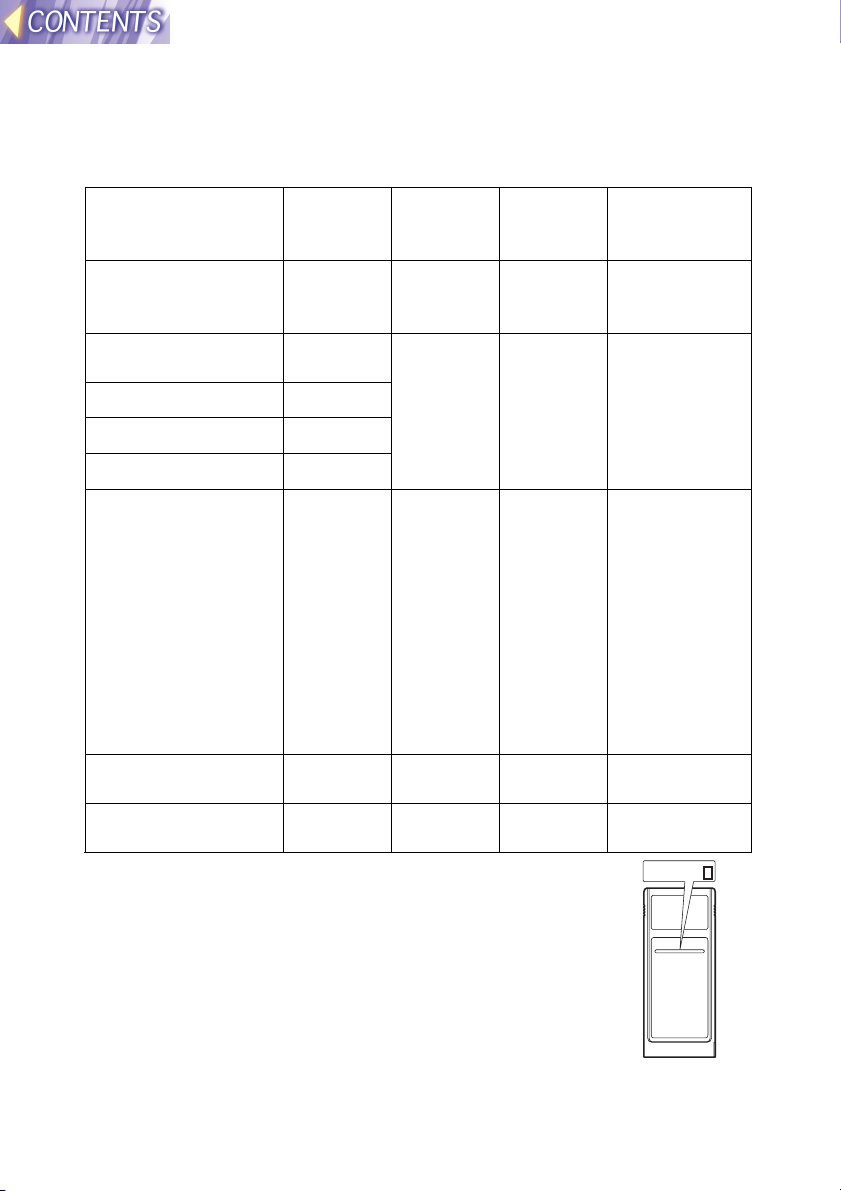
* To check the region of intended use for the wireless card
which you have purchased, check the last digit of the
product number which appears on the label on the reverse
side of the card in the position shown in the illustration at
right.
ETSI
300.328
300.328
3 1~13 2412 MHz ~
4 10,11 2457 MHz ~
Note:
• The wireless card cannot be used in countries other
than the country of purchase. If you try to use it in other
countries, you may be infringing the radio transmission
laws and regulations of that country.
-6-
2472 MHz
2462 MHz
2472 MHz
N5HBD0000002
Page 7
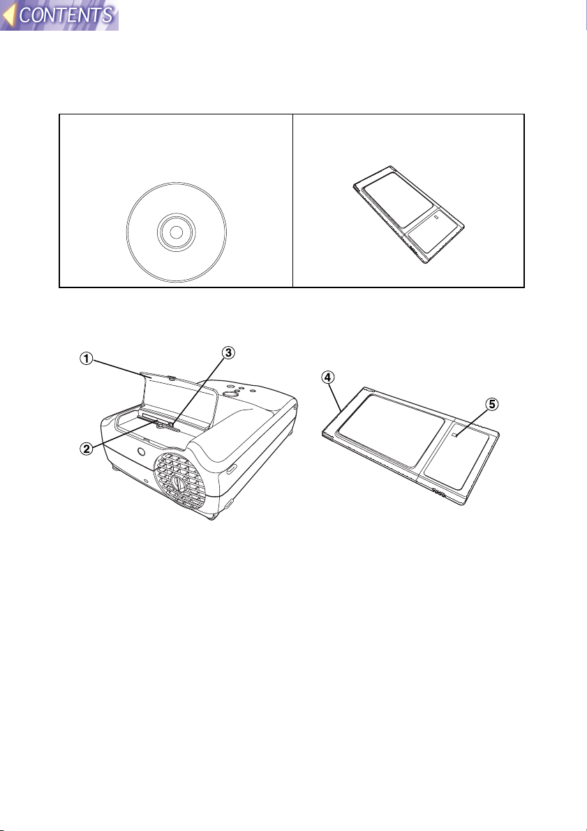
Check accessories
The following accessories are included with the projector, in addition to the
accessories which are listed in the separate Operating Instructions.
CD-ROM ... 1 pc. (Wireless
Manager, Driver, Configuration
Utility, JPEG Convertor, Operating
Instructions)
Wireless Card ... 1 pc.
Names of each part
Wireless card slot
#### Slot cover
Covers the card slot.
$$$$ Card slot
Insert the wireless card into here.
%%%% Eject switch
Use to remove the wireless card from the card slot.
Wireless card
&&&& Connector
This connector is for connecting the wireless card to the projector’s
card slot. Be careful not to touch the connector.
(((( Wireless card power monitor
Illuminates when the wireless card is operating.
-7-
Page 8
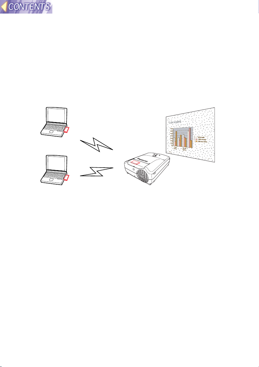
Wireless image transfer system for the projector
This system is designed to let you project images for presentations and
other purposes by transmitting images that appear on a computer screen
to the projector. This is possible by inserting the specified wireless cards
into the projector and into the computers that are to be used. More than
one computer can be connected to the projector in this way.
System diagram
Projected image
Note:
• An optional wireless card (ET-CDWL1 series) must be inserted into the
computer(s).
-8-
Page 9
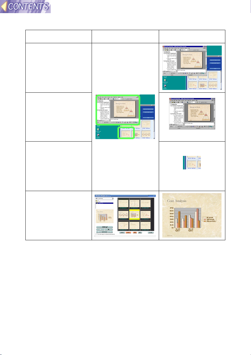
Transferable images
#### Screen shots of
a whole
computer
screen
$$$$ Screen shots of
the active
window on a
computer
screen
%%%% Screen shots of
specified areas
of a computer
screen
&&&& BMP, JPEG and
PNG images
Computer screens Projection images
-9-
Page 10

Main functions of the application software
Software Functions
Driver
Configuration Utility
Wireless Manager • Storing multiple network settings
JPEG Convertor • Converting Microsoft PowerPoint files to
• Basic software for carrying out wireless
communication with a optional wireless card
connected to a computer
• Capturing computer screen images and sending
the images to the projector
• Selecting images from a list and transferring
them to the projector
• Automatic playback
DCF-compliant JPEG images
• Converting JPEG, BMP and TIFF images to
DCF-compliant JPEG images
• Sorting images
• Converting images sizes and compression ratios
Notes on using the projector
The following points must always be observed.
• Do not drop the projector or subject it to strong shocks.
• Do not let the projector get wet.
• Do not use unnecessary force to open and close the slot cover.
• Do not use wireless cards which are cracked or bent.
• Do not use the projector in places with high humidity such as bathrooms,
or in places which are very dusty such as warehouses.
Please make sure that you understand the following before
using the wireless card.
• Panasonic shall not be liable for any direct or indirect losses which may
be incurred as a result of using this product or from any malfunction of
this product.
• Panasonic takes no responsibility for any loss or corruption of data
caused by this product.
• Panasonic takes no responsibility for any unauthorized disclosure of data
transmitted by means of this product.
-10-
Page 11

Explanation of terms
The following terms appear throughout these Operating Instructions, and
are defined here for easy reference.
LAN
Abbreviation for Local Area Network. A network which is small in scale,
such as an intra-company network. Both wired LANs and wireless LANs
can be found. This projector uses a wireless LAN.
TCP/IP
Abbreviation for Transmission Control Protocol/Internet Protocol. The
standard protocol for the Internet.
A protocol is a set of specifications and agreements which allow two
computers to communicate with each other.
IP Address
An Internet Protocol (IP) is a protocol used for the transmission of data,
and the IP address is the address of the destination where the data is
being sent to. Identical IP addresses cannot be used for two different
devices within the one LAN.
Subnet Mask
Limits the range of IP addresses that can be assigned to a computer when
using a TCP/IP connection, in order to allow a network to be divided into
several sub-sections. The parameters which divide the sub-network in this
way are called the subnet mask.
Gateway
A junction point where different types of networks are connected to each
other.
It is used to refer to the hardware and software which is used when
connecting a particular network to another network which has been set up
under different network specifications. It makes adjustments for differences
in the protocols used by the two networks and makes it possible to connect
to other networks.
DHCP
Abbreviation for Dynamic Host Configuration Protocol. A function which
automatically assigns IP addresses to each computer that is connected to
a network. If a device which functions as a DHCP server is located within a
LAN, this device automatically assigns IP addresses to computers which
are connected to the LAN. Not available with this product.
-11-
Page 12

Ad Hoc Mode
A mode for direct communication between the projector and a computer
with an optional wireless card.
Infrastructure Mode
A mode for communication via an access point which is connected to a
wired LAN.
A computer without an optional wireless card can still be used to send
images to the projector via an access point.
Access Point
A point of connection between a wired LAN and a wireless LAN.
Channel
If several access points which use the same frequency band are located
near each other, radio transmission interference between these access
point can occur when they are being used, and this can in turn result in
drops in transmission speeds. In order to reduce this problem when using
wireless LANs, the frequency band can be divided into 11 channels for
communication purposes. (The number of channels varies depending on
the country.) However, because interference between adjacent channels
can occur, the channels available for use are normally spaced 2 or 3
channels apart from each other.
SSID
Abbreviation for Service Set ID. Wireless LANs that utilise access points
require the setting of SSID identification codes in order to distinguish
between devices which are a part of the LAN and devices which are not.
WEP
Abbreviation for Wired Equivalent Privacy. A method of encrypting
transmitted data. An encryption key is generated and is given only to the
person who will be using the transmitted data, in order to prevent third
parties from decoding the transmitted data. Not available with this product.
-12-
Page 13

JPEG
Abbreviation for Joint Photographic Experts Group. JPEG is the name of
an international organisation which was jointly established by the ISO and
the ITU-TS (formerly the CCIT), but the term is normally used to refer to the
specifications for the still picture compression algorithm which was
formulated by the JPEG. This algorithm allows still images such as
photographs, single frames of moving images and scanned images to be
compressed to up to 1/100th of their original sizes. However, images which
are compressed in this way cannot be fully restored to their original quality
(some deterioration in quality occurs), so that compression rates of 1/5 to
1/30 are normally used. Because of differences in color separation, two
format sub-types are used: RGB (red, green and blue) and CMYK (cyan,
magenta, yellow, black).
The projector and the JPEG Convertor software do not support the CMYK
sub-type of JPEG file.
BMP
Abbreviation for BitMaP. This is the standard image format for the
bitmapped files (image files consisting of a collection of dots) which are
handled by Windows.
Color levels of monochrome, 16 colors, 256 colors and 16.7 million colors
are supported.
PNG
Abbreviation for Portable Network Graphics.
A high compression rate file format that provides restorable compression
for line raster images.
Because it uses restorable compression, it does not result in any loss of
image resolution unlike JPEG.
RLE
Abbreviation for Run Length Encoding. It can be used to achieve high rates
of compression for image files which contain large areas of a single color.
RLE can be used with monochrome, 16-color and 256-color BMP image
files. (JPEG Convertor does not support files compressed using RLE.)
TIFF
Abbreviation for Tagged-Image File Format. This type of file is used to
exchange documents between computers. Color levels of monochrome,
256 colors and 16.7 million colors are supported. TIFF files in 16.7 million
color format can include transparent color.
-13-
Page 14

LZW
Abbreviation for Lempel-Ziv-Welch. LZW is a compression method used
for TIFF files, and is named thus because it was developed by three people
named Lempel, Ziv and Welch. It compresses the files by converting
patterns within the images into short codes. There is no deterioration in
image quality resulting from compression, but high rates of compression
which are comparable to JPEG files cannot be expected to be obtained.
(JPEG Convertor does not support files compressed using LZW.)
DCF
Abbreviation for Design rule for Camera File system. DCF is a standard
which was established by the Japan Electronic Industry Development
Association (JEIDA) with the aim of realising a common image file format,
directory name format and file name format for the images used with digital
still cameras. It is based on recommendations such as Exif Version 2.1.
Exif 2.1
Abbreviation for Exchangeable Image File Format. This is an image file
format which was established by the Japan Electronic Industry
Development Association (JEIDA). It defines the common information
format and range of application for images used with digital still cameras,
centring around TIFF and JPEG-format images. Version 2.1 is the latest
version of the Exif standard.
PowerPoint
Application software for creating presentations which is included as part of
Microsoft Office. 95, 97 and 2000 versions are available, but the JPEG
Convertor software which is bundled with the projector is only compatible
with the 97 and 2000 versions.
-14-
Page 15
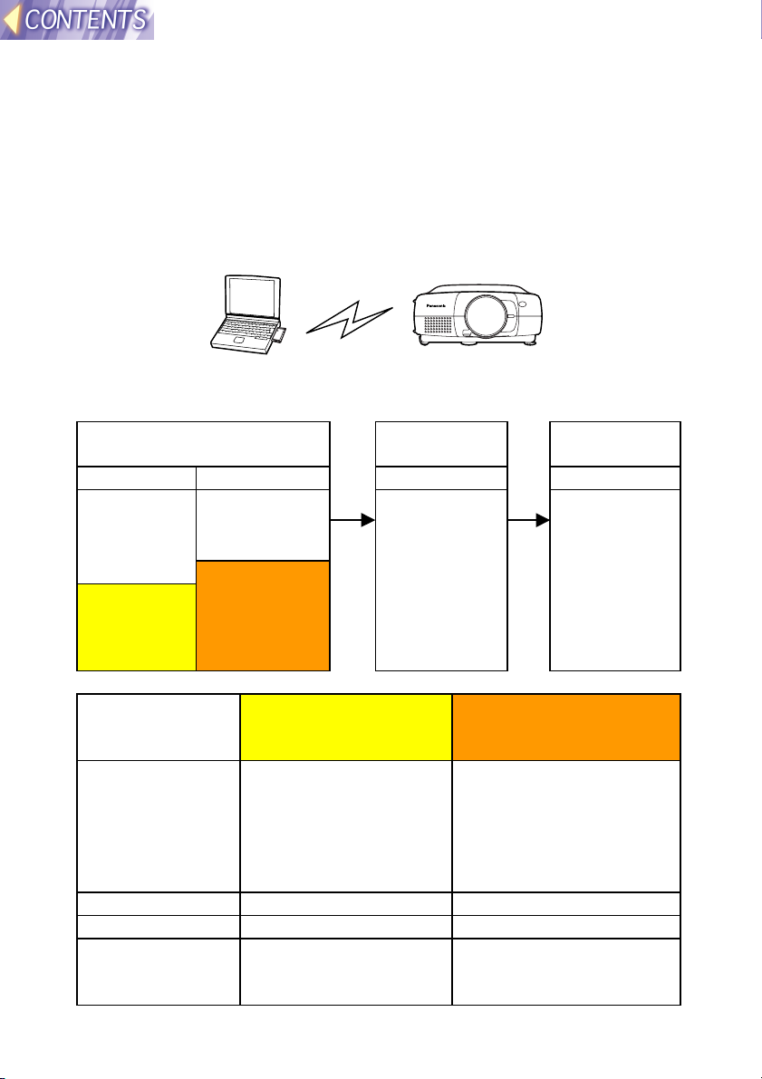
Wireless function preparation
The methods of transferring images using a wireless LAN can be broadly
classified into three types according to the environment you are currently
using.
(1) Firstly, when using the wireless function
Insert an optional ET-CDWL1 series wireless card into a computer, and
use Ad Hoc mode so that the computer can carry out direct wireless
communication with the projector.
Computer Projector
Setting procedure
Set the computer and the projector according to the following procedure.
Preparation & settings Check
communication
<Projector> <Computer> <Computer> <Computer>
Inserting the
wireless
card (page
19)
LAN
settings
(page 22)
Inserting the
wireless card
(page 28)
Network
settings using
Wireless
Manager
(page 38)
Use Wireless
Manager to
check
communicatio
n with the
projector
(page 41)
Transmit
images
Use Wireless
Manager to
transmit the
images (page
42)
Setting example
Setting item Projector LAN
settings
IP ADDRESS 192.168.10.10 (default)
If using two or more
projectors, use different
addresses for each.
SUBNET MASK 255.255.255.0 (default) 255.255.255.0
MODE AD HOC Ad Hoc
CHANNEL 11 (default)
Use the same setting
for the computer.
Network settings using
Wireless Manager at
computer
Set the address to
something like
192.168.10.11 or
192.168.10.12. Do not
use the same address as
used for the projector.
11
Use the same setting for
the projector.
-15-
Page 16
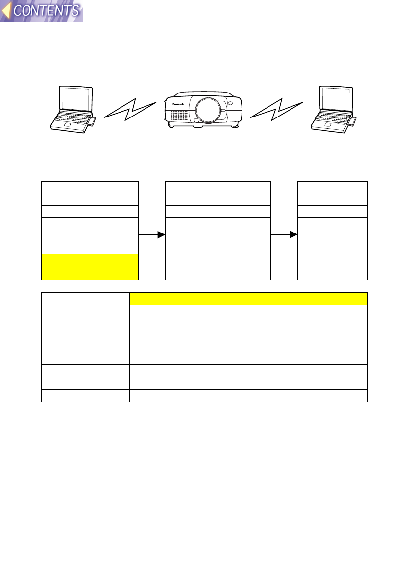
(2) If already using computers for wireless
transmission (Ad Hoc mode)
Use the existing wireless cards for the computers to carry out direct
wireless communication with the projector in Ad Hoc mode.
Computer Projector Computer
Setting procedure
Set the computer and the projector according to the following procedure.
Preparation &
settings
<Projector> <Computer> <Computer>
Inserting the
wireless card (page
19)
LAN settings (page
22)
Check communication Transmit
images
Use Wireless
Manager to check
communication with
the projector (page
41)
Use Wireless
Manager to
transmit the
images (page
42)
Setting example
Setting item Projector LAN settings
IP ADDRESS Set the computer IP address to an address with the
last number different.
e.g. If the computer IP address is 192.168.10.11, set
the projector’s address to something like
192.168.10.12.
SUBNET MASK Use the same setting for the computer.
MODE AD HOC
CHANNEL Use the same setting for the computer.
Note:
• The computer settings can be used without further changes. However, if
using the WEP function, communication with the projector will not be
possible. You will first need to turn off the WEP function for all computers
which are to communicate with the projector.
Furthermore, when the WEP function is turned off, the data encryption
function will also be turned off, so it is recommended that you use a
feature such as the Sharing Settings for folders to set password
protection for your data. Ask your network administrator for further
details.
• If you any wireless cards other than the optional ET-CDWL1 series,
correct operation cannot be guaranteed.
-16-
Page 17
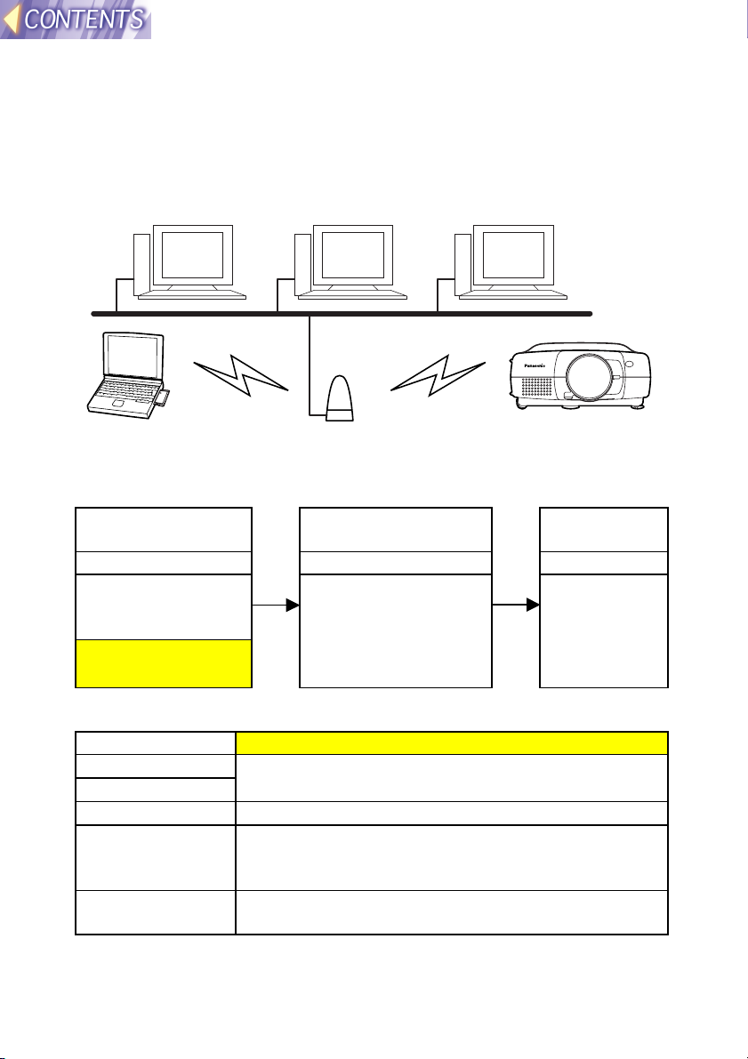
(3) When using an existing access point for
wireless communication
Use the access point to carry out wireless communication between the
computer and the projector in Infrastructure mode. Some access points
may not let you make connections.
Computer Computer Computer
LAN
Computer Access point Projector
Setting procedure
Set the computer and the projector according to the following procedure.
Preparation &
settings
<Projector> <Computer> <Computer>
Inserting the
wireless card (page
19)
LAN settings (page
22)
Check communication Transmit
images
Use Wireless
Manager to check
communication with
the projector (page
41)
Use Wireless
Manager to
transmit the
images (page
42)
Setting example
Setting item Projector LAN settings
IP ADDRESS
SUBNET MASK
MODE INFRASTRUCURE
CHANNEL Set to the same CHANNEL as the CHANNEL for the
SSID Set to the same SSID as the SSID for the access
Ask your network administrator for details on
settings.
access point. (Ask your network administrator for
details.)
point. (Ask your network administrator for details.)
Note:
• If either the projector or computer is out of the range of the access point,
use Ad Hoc mode as described in page 15.
-17-
Page 18

• The projector’s SSID can be up to 16 characters in length, and must
consist of capital letters (A-Z) and numerals (0-9). Accordingly, if the
SSID that has been set for the access point is invalid as an SSID for the
projector, ask your network administrator to change the access point’s
SSID to one that can be used by the projector.
• The projector is not compatible with DHCP. For LANs that use DHCP
servers, a fixed IP address needs to be assigned to the projector for it to
be used. Ask your network administrator for further details.
• If using the WEP function, communication with the projector will not be
possible. You will first need to turn off the WEP function for all computers
which are to communicate with the projector.
Furthermore, when the WEP function is turned off, the data encryption
function will also be turned off, so it is recommended that you use a
feature such as the Sharing Settings for folders to set password
protection for your data. Ask your network administrator for further
details.
-18-
Page 19
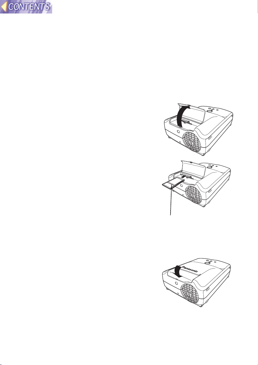
Installing and removing the wireless card
Inserting the wireless card
#### Turn off the power supply for the projector.
Turn of the power supply for the projector while referring to “Turning off
the power” on page 23 of the PT-L711XU Operating Instructions.
$$$$ Open the slot cover.
%%%% Insert the wireless card as shown in
the illustration at right.
Hold the wireless card so that the power
monitor is facing upward when inserting it,
and push it all the way in until it locks.
Wireless card power monitor
Note:
• Make sure the wireless card is facing the correct way when inserting it. If
you try to force the wireless card the wrong way into the slot, it will
damage the wireless card and the projector.
&&&& Close the slot cover.
-19-
Page 20
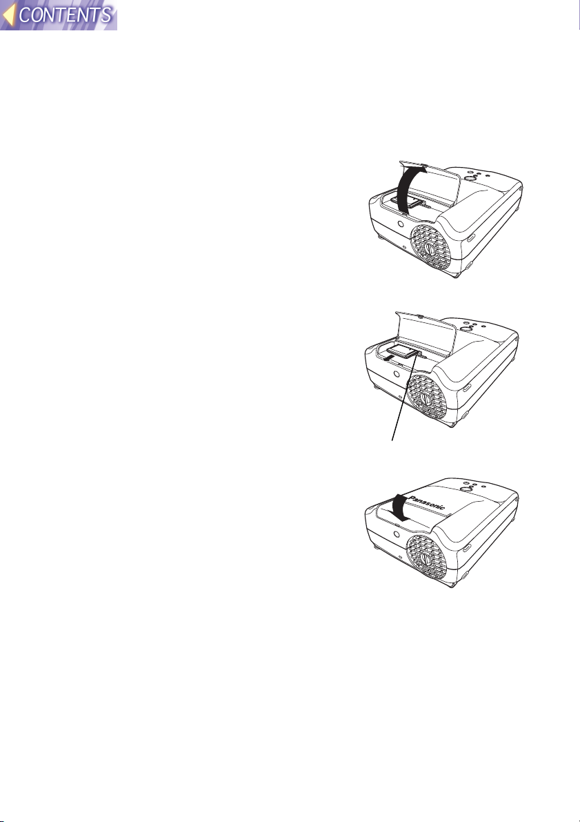
Removing the wireless card
#### Turn off the power supply for the projector.
Turn of the power supply for the projector while referring to “Turning off
the power” on page 23 of the PT-L711XU Operating Instructions.
$$$$ Open the slot cover.
%%%% Press the eject switch.
When you press the eject switch, it pops
out.
&&&& Push in the eject switch and then
remove the wireless card.
Eject switch
(((( Close the slot cover.
-20-
Page 21
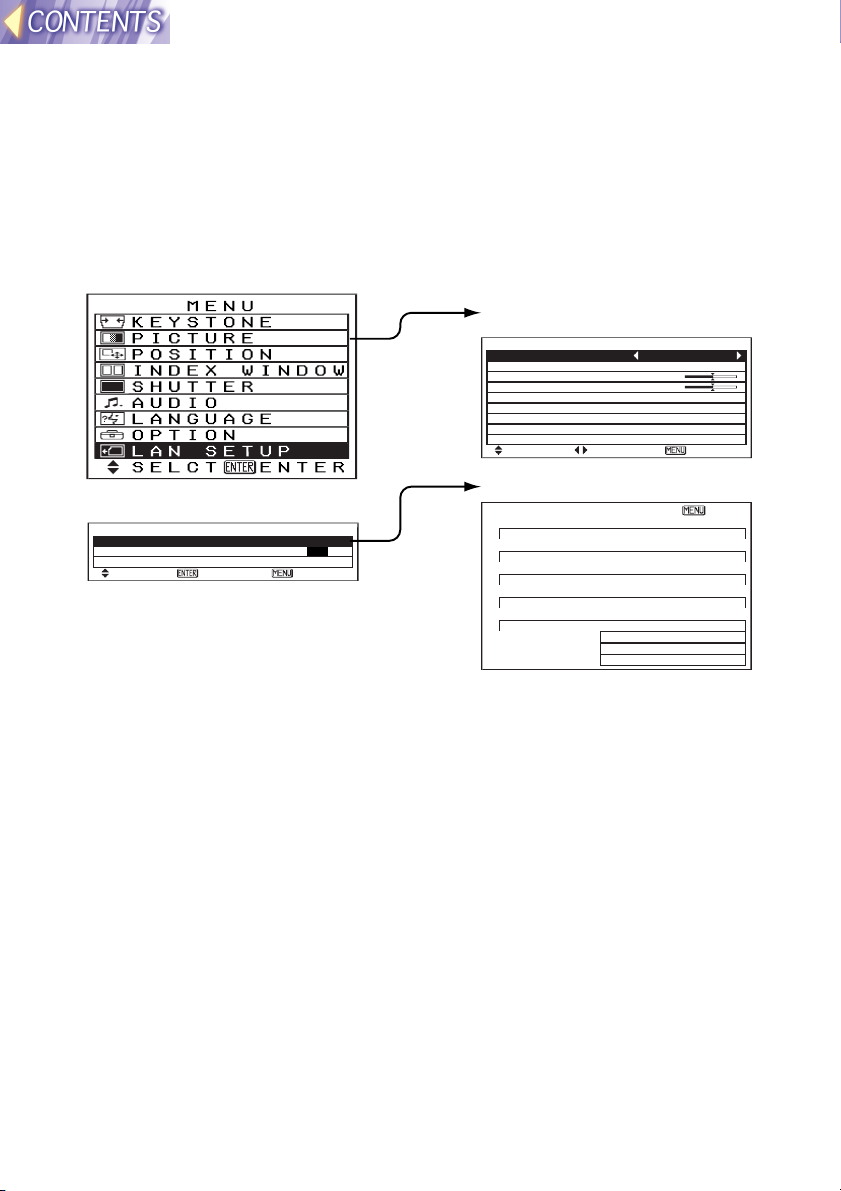
On-screen menus
List of menu screens
Adjustments and setting changes for this projector are carried out using
on-screen menu operations. The configuration for the projector’s LAN
SETUP menu is shown in the illustration below.
MAIN MENU
PICTURE
PICTURE
PICTURE MODE NATURAL
BRIGHT 32
CONTRAST 32
SELCT ADJ ESC
LAN SETUP(page22)
LAN SETUP
STATUS LAN 1
LOCK SETUP OFF ON
SETUP
SELCT ENTER ESC
[LAN 1] ESC
IP ADDRESS
192.168. 10. 10
SUBNET MASK
255.255.255. 0
HOSTNAME
PANASONIC PRJ-01
MODE
AD HOC
SSID
SSID
CH 11
ENCRYPT OFF
KEY 0- 0
Note:
Please refer to the separate PT-L711XU Operating instructions for details
on main menu items other than LAN SETUP.
STATUS(page22)
-21-
Page 22
Projector LAN settings
After inserting the wireless card into the projector, you need to make the
necessary LAN settings.
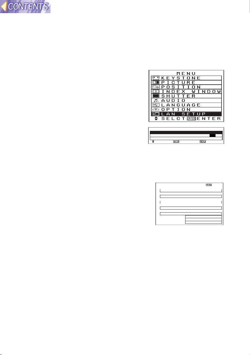
Displaying the LAN Setup screen
#### Press the MENU button. The MAIN
MENU screen will be displayed.
$$$$ Press the FFFF or GGGG button to select
“LAN SETUP”.
%%%% Press the ENTER button. The LAN
SETUP screen will be displayed.
STATUS
LAN SETUP
STATUS LAN 1
LOCK SETUP OFF ON
SETUP
SELCT ENTER ESC
The projector can store up to five different types
of LAN settings. The STATUS command can
be used to view the settings which are currently
selected.
Press the F or G button on the projector’s
control panel or the remote control to select
[LAN 1] ESC
IP ADDRESS
192.168. 10. 10
SUBNET MASK
255.255.255. 0
HOSTNAME
PANASONIC PRJ-01
MODE
AD HOC
SSID
SSID
CH 11
ENCRYPT OFF
KEY 0- 0
“STATUS”, and then press the [ENTER] button.
The STATUS screen will be displayed.
Note:
• Refer to SETUP on page 23 for details on making the various LAN
settings.
• If the CH display appears in red, it means that the selected channel
cannot be used. Use the SETUP menu to change the CHANNEL setting.
-22-
Page 23

LOCK SETUP
The LOCK SETUP setting is automatically changed to ON after the SETUP
function has been used, in order to prevent accidental changes from being
made to the LAN settings.
When LOCK SETUP is ON, the SETUP function cannot be used. Before
using the SETUP function, you need to change the LOCK SETUP setting
to OFF.
Use the F or G button to select “LOCK
SETUP”, and then press the I or H
button to change the setting.
LAN SETUP
STATUS LAN 1
LOCK SETUP OFF ON
SETUP
SELCT ADJ ESC
SETUP
In order to make it easier to configure the projector’s network settings, the
SETUP function displays the following setting screens in order from # to
-.
Before using the SETUP function, use the “SELECT SETUP” menu to
select the LAN settings that you would like to make or change. Also check
that “LOCK SETUP” is OFF.
Use the F or G button on the projector or
remote control unit to select “SELECT
SETUP”, and then press the ENTER
button to start making the settings.
Note:
• When the final settings are made, “WAIT A MINUTE” appears briefly,
and then the LAN is reset.
• If you press the MENU button at any time before the final settings have
been made, all setting changes will be discarded and the previous
settings will be restored.
####
SELECT
The projector can store up to five
different types of LAN settings.
This is useful when using the
projector in different places with
different network environments.
Use the I or H button to select
the desired type of setting and then
press the [ENTER] button.
-23-
LAN SETUP
STATUS LAN 1
LOCK SETUP OFF ON
SETUP
SELCT ENTER ESC
SETUP
SELECT
LAN 1
LAN 2
LAN 3
LAN 4
LAN 5
Page 24

$$$$
MODE
This can be set to either “AD HOC”
or “INFRASTRUCTURE”. If using
SETUP
MODE
AD HOC
INFRASTRUCTURE
methods (1) or (2) as described on
page 15 of “Wireless function
preparation”, set to “AD HOC”. If
using method (3) in “Wireless
function preparation”, set to
“INFRASTRUCTURE”.
Use the I or H button to change
the setting, and then press the
ENTER button.
Some of the settings used differ between AD HOC mode and
INFRASTRUCTURE mode.
%%%%
Channel
AD HOC
This lets you set the channel. You must set the channel to the
same channel that is being used by the wireless card of the
transmitting computer.
In INFRASTRUCTURE mode, operation is usually possible
regardless of the settings used. However, for some access points,
you may need to set the channel to the same channel that is used
by the access point, otherwise communication may not be possible.
Use the I or H button to change the setting, and then press the
ENTER button.
SETUP
CH
11
INFRASTRUCTURE
Note:
• The channels that can be used will vary depending on the
country (page 6).
-24-
Page 25

In Ad Hoc mode, make the “IP
&&&&
ADDRESS” setting in step
AD HOC
( below.
INFRASTRUCTURE
SSID
If using Infrastructure mode,
change the “SSID” setting to the
same SSID for the access point
that will be used for
communication. However, the
projector’s SSID can be up to 16
characters in length, and must
consist of capital letters (A-Z)
and numerals (0-9).
Accordingly, if the SSID that has
been set for the access point is
invalid as an SSID for the
projector, ask your network
administrator to change the
access point’s SSID to one that
can be used by the projector.
Use the F or G button to
change the characters, and use
the I or H button to change
the character position. When
you have finished, press the
ENTER button.
SETUP
SSID
SSID
((((
IP ADDRESS
This lets you set the projector’s IP address.
Refer to page 15 of “Wireless function preparation” while making
this setting. However, the projector’s IP address cannot be the
same as the IP address that is being used by the transmitting
computer.
Use the F or G button to change the number position, and use the
I or H button to set the numbers. When you have finished, press
the ENTER button.
SETUP
IP ADDRESS
192.168. 10. 10
-25-
Page 26

))))
SUBNET MASK
AD HOC
INFRASTRUCTURE
This lets you set the projector’s subnet mask.
Refer to page 15 of “Wireless function preparation” while making
this setting.
Use the For G button to set the numbers, and use the I or H
button to change the number position. When you have finished,
press the ENTER button.
SETUP
SUBNET MASK
255.255.255. 0
****
HOSTNAME
This lets you set a network name for the projector. The projector’s
host name can be up to 16 characters in length, and can contain
capital letters (A-Z), numerals (0-9) and “-” (hyphen).
Use the F or G button to change the characters, and use the I or
H button to change the character position. When you have
finished, press the ENTER button.
SETUP
HOSTNAME
PANASONIC PRJ-01
++++
ENCRYPT
You can use this function to encrypt the image data. However,
when encryption is enabled, it takes longer for images to be
transferred.
To enable encryption, set to “ON”. If set to “OFF”, encryption is not
carried out.
The Wireless Manager encryption settings on page 52 must be
carried out.
Use the I or H button to change the setting. When you have
finished, press the ENTER button.
SETUP
ENCRYPT
ON
OFF
-26-
Page 27

----
AD HOC
INFRASTRUCTURE
KEY
This appears when the ENCRYPT setting in step + is ON.
Set an encryption key using a combination of numbers from “0-0” to
“255-255”.
When an encryption key has been set, you must set the same
encryption key for the Wireless Manager (see page 52), otherwise
communication will not be possible.
Use the F or G button to set the numbers, and use the I or H
button to change the number position. When you have finished,
press the ENTER button.
SETUP
KEY
0- 0
-27-
Page 28

Setting up the computer wireless card
When using an optional ET-CDWL1 series wireless card, it must be
installed to a computer and the driver software and Configuration Utility
must be installed into the computer.
This section describes the method of setting up the optional
ET-CDWL1 series wireless card.
If you have already set up your computer’s wireless card, you
can skip to “Using the Wireless Manager” on page 37.
Setup procedure
Carry out the following steps in the order given to set up the computer’s
wireless card.
Install the
card.
(Page 28)
Install the
driver.
(Page 29)
Install the
utilities.
(Page 36)
Use Wireless
manager to
make
network
settings.
(Page 38)
Installing and removing the computer’s wireless card
Installing the wireless card
Hold the wireless card so that the power monitor is facing upward, and
insert it into the computer’s PC card slot as far as it will go. Make sure that
the card is facing the right way.
Computer Wireless card
Note:
• Read the documentation provided with the computer at this time also.
• If you try to force the wireless card the wrong way into the slot, it will
damage the wireless card and the projector.
-28-
Page 29

Removing the wireless card
#### Close Wireless Manager if it is running.
$$$$ Left-click on the PC Card icon (
) on the taskbar at the
bottom-right corner of the screen.
Note:
• If the PC Card icon does not appear in the taskbar at the bottom-right of
the screen, click “Start”, point to “Settings”, click “Control Panel” and then
open “PC Card”. Click the “Show control on taskbar” check box and then
click “OK”.
%%%% Select “Stop Panasonic Wireless
Card”.
&&&& The screen shown at right will
appear. Click “OK” to remove the
wireless card.
Installing the driver
When the wireless card is inserted, the driver installation screen appears.
The driver can be found on the CD-ROM which is included with the
projector as an accessory.
Install the driver by following the procedure below.
For Windows 98
Note:
• The Windows 98 Setup CD-ROM may be needed while the driver is
being installed.
#### When the wireless card is inserted,
the “Add New Hardware Wizard” will
start. Click “Next”.
-29-
Page 30

$$$$ Select “Search for the best driver for
your device” and then click “Next”.
%%%% Insert the accessory CD-ROM into
the CD-ROM drive of the computer,
select “CD-ROM drive” and then
click “Next”.
&&&& When “netcw10.inf” appears, click
“Next”.
Driver installation will start.
(((( Click “OK” without changing any of
the detailed settings.
Note:
• Use the Wireless Manager to change the
wireless card settings (page 38).
)))) Click “Finish”.
-30-
Page 31

**** Click “Yes”. The computer will then
re-start.
Once the computer has restarted,
installation of the driver will be complete.
Next, you should check the protocol (page 32).
For Windows 95
• If using Windows 95, refer to the installation procedure for Windows 98.
For Windows 2000
#### When the wireless card is inserted,
the Found New Hardware Wizard will
start. Click “Next”.
$$$$ Select “Search for a suitable driver
for my device” and then click “Next”.
%%%% Insert the accessory CD-ROM into
the CD-ROM drive of the computer,
select “CD-ROM drive” and then
click “Next”.
&&&& When “netcw10.inf” appears, click
“Next”.
-31-
Page 32

(((( Click “Yes”.
Driver installation will start.
)))) Click “Finish”.
Installation of the driver will be complete.
Next, you should check the protocol
(page 34).
Checking the protocol
TCP/IP is used to transfer the images from the computer to the projector.
Check that the computer has TCP/IP available.
For Windows 98
Note:
• The Windows 98 Setup CD-ROM may be needed while the driver is
being installed.
#### Click “Start”, point to “Settings”, and
click “Control Panel”.
$$$$ Double-click the “Network” icon.
-32-
Page 33

%%%% Check that “TCP/IP” is present in the
list of installed network components.
• If TCP/IP is installed, click “Cancel” and
install the Configuration Utility. (See page
36.)
• If TCP/IP is not installed, continue on to step
&
below.
&&&& Click “Add”.
(((( Select “Protocol” and then click
“Add”.
)))) Select “Microsoft” in the
Manufacturers column, select
“TCP/IP” in the Network Protocols
column, and then click “OK”.
-33-
Page 34

**** Click “OK”.
++++ Click “Yes”. The computer will then
re-start.
• When the computer has restarted, TCP/IP
will be installed. Continue with the installation
of the Configuration Utility (page 36).
For Windows 95
• If using Windows 95, refer to the protocol checking (adding) procedures
for Windows 98.
For Windows 2000
#### Click “Start”, point to “Settings”, and
click “Network and Dial-up
Connections”.
$$$$ Select “Local Area Connection”, click
the right mouse button, and select
“Properties”.
• If there are several “Local Area Connection”
entries, select the one which gives
“Panasonic Wireless Card” as the card name
when you click on it with the right mouse
button.
Card name
-34-
Page 35

%%%% Check that “Internet Protocol
(TCP/IP)” is present and selected in
the “Components checked are used
by this connection” list.
• If TCP/IP is installed, click “Cancel” and
install the Configuration Utility. (See page
36.)
• If TCP/IP is installed but the check box is
unselected, select the check box to enable
TCP/IP.
• If TCP/IP is not installed, continue on to step
&
below.
&&&& Click “Install”.
(((( Select “Protocol” and then click
“Add”.
)))) Select “Internet Protocol (TCP/IP)”
and then click “OK”.
-35-
Page 36

**** Click “Close”.
• TCP/IP will be added. Continue with the
installation of the Configuration Utility (page
36).
Installing the Configuration Utility
You need to install the Wireless LAN Configuration Utility to the computer
in order to use the optional ET-CDWL1 series wireless card. The Wireless
LAN Configuration Utility is contained in the CD-ROM which is included
with the projector as an accessory. Follow the steps below to install the
Configuration Utility.
#### Open the “English” folder in “CONFIGURATION UTILITY” on
the CD-ROM.
$$$$ Double-click “Setup.exe”.
%%%% Follow the instructions which appear on the screen to
complete the installation.
&&&& Start the Configuration Utility.
You can also start the Configuration Utility by
clicking “Start”, pointing to “Programs”, pointing
to “Wireless Card”, and then pointing to
“Configuration Utility”. When the Configuration
Utility starts, the menu screen appears and an
icon appears on the taskbar at the bottom-right
corner of the screen.
• Be sure to start the program only once.
The various wireless card settings are made using the
Wireless Manager which is also supplied on the accessory
CD-ROM. There is no need to change any settings using the
Configuration Utility.
-36-
Page 37

Displaying the Configuration Utility
• If you use the mouse to left-click on the Configuration Utility icon in the
taskbar, a menu appears.
• Refer to the online help for the Configuration Utility for details on using
the Utility.
Using the Wireless Manager
The Wireless Manager is a program that runs on the computer and is used
to send images to the projector. The Wireless Manager is included on the
CD-ROM that is supplied with the projector as an accessory. Read the
“Read this first” that is included with the projector for instructions on
installing the Wireless Manager.
Wireless Manager capabilities
• The Wireless Manager is used to make network settings. It lets you
register multiple network settings so that you can easily select the
settings that apply to the network you are currently using. (See page 38)
• It also lets you capture images from the computer screen and transmit
them to the projector so that they can be projected. (See page 43)
• You can also use the Wireless Manager to view a list of existing image
files in folders, and to select images from these folders for transmitting to
the projector for display. Furthermore, the images can be played back
automatically. (See page 48)
• The Wireless Manager is compatible with BMP, JPEG and PNG image
formats. (However, it cannot handle files that are larger than 4 MB in
size.)
Starting and closing the Wireless Manager
Before starting Wireless Manager
Check the computer settings by following the procedure below, and make
any changes that are necessary.
• Click with the right mouse button on an empty part of the desktop and
select "Properties". Then open the "Settings" tab in the "Display
Properties" window and change the "Colors" setting to "High Color (16
bit)" or greater. (For Windows 95, open the "Display Details" tab.)
• Follow the same procedure as above to open the "Settings" tab in the
"Display Properties" window. Then click the "Advanced" button, and
change the "Font Size" setting to "Small Fonts". (For Windows 95, open
the "Display Details" tab.)
-37-
Page 38

You can start the Wireless Manager by clicking
“Start”, pointing to “Programs”, pointing to
“Wireless Manager” and then click the
“Wireless Manager”. When the Wireless
Manager starts, an icon appears on the taskbar
at the bottom-right corner of the screen.
• If you right-click on the icon on the taskbar,
a menu appears. Select an item in the
menu and click the left mouse button to
display the respective window.
• To close the Wireless Manager, choose
“End”.
Computer network settings
The computer’s network settings must be correct in order to be able to
send images to the projector. Multiple network setting values can be stored.
When TCP/IP settings are made or changed, it is sometimes necessary to
restart the computer before they can take effect.
Wireless Manager cannot be used to change the settings if
you are using a wireless card other than the optional
ET-CDWL1 series card. You will need to use the software that
is supplied with the wireless card in order to change the
settings.
Right-click on the icon in the taskbar, select
“Option” to display the Option window, and
then select “SETTING NETWORK”.
-38-
Page 39

Make the following settings.
#### Select Setting
If creating several network
settings, use the G button to
select a setting.
$$$$ Setting Name
Lets you type a name for the
network setting.
(Example) LAN1
%%%% Create
Creates a new network setting.
&&&& Delete
Deletes the currently-displayed network setting.
(((( Copy
Creates a new network setting and copies the contents of the
currently-displayed network setting to the new setting.
)))) NIC (Network Interface Card)
Selects the wireless card to be used.
**** LAN card’s number
Type in the last digit of the product number for the wireless card that
you are using (see page 6).
TCP/IP
++++ Use DHCP
Select if you would like to assign an IP address so that the computer
can use a DHCP server.
---- IP address
Type in the computer’s IP address. The computer’s IP address cannot
be the same as the projector’s IP address or another computer’s IP
address.
Refer to page 15 of “Wireless function preparation” while making this
setting.
.... Subnet Mask
Type in the subnet mask.
Refer to page 15 of “Wireless function preparation” while making this
setting.
//// Gateway
Type in the gateway address.
This setting is not required for communication with the projector.
This setting is not compatible with the metric settings for Windows 2000.
If metric settings are required, make the setting using the “Advanced
TCP/IP settings” window in Windows 2000.
-39-
Page 40

Wireless LAN
0000 Mode
Set to either “Ad Hoc” mode or
“Infrastructure” mode.
Refer to page 15 of “Wireless
function preparation” while
making this setting.
Note:
• If setting to “Ad Hoc” mode, do
not set to “802.11Ad Hoc”.
1111 SSID
Change the name so that it is the same as the SSID that has been set
for the access point to be used for transmissions in Infrastructure mode.
2222 Channel
Set the channel to be used during Ad Hoc mode. The projector must be
set to the same channel.
3333 READ CURRENT SETTING
Loads the setting values which are currently set for the wireless card.
When all settings have been completed, click “OK”. It may then
be necessary to restart Windows.
After making the settings, do the “Checking communication
with the projector” described on page 41.
-40-
Page 41

Checking communication with the projector
Right-click on the icon in the taskbar, and select
“Search Projector”.
• If communication with the projector is
successful, the host name and IP address for
the projector will appear.
• Select the projector for transmitting the
images to, and then click “OK”.
• If you would like to repeat the search for a
projector, click “SEARCH”.
Note:
• Projector searching cannot be carried out for
approximately 30 seconds after the projector
power is turned on, even if “Search Projector”
is selected.
• If the IP addresses have not been set for projectors and computers within
the same network group, searching may not be carried out correctly.
• If the message “No projector detected.”
appears as shown at right, the projector
and/or computer settings may be incorrect.
Check the settings and then repeat the
search.
-41-
Page 42

Basic image transmission examples
(Example 1) Capturing computer screen images and projecting
them
Projector
The current image on the computer screen can be captured and
transmitted to the projector for projecting. (See page 43.)
(Example 2) Projecting already-existing images
Projector
Images which already exist and are in BMP, JPEG or PNG format can be
selected from an image list and transmitted to the projector for projecting.
Furthermore, the images can be played back automatically. (See page 48.)
(Example 3) Converting Microsoft PowerPoint data for
projection using the JPEG Convertor
Projector
Microsoft PowerPoint files can be converted into JPEG files using the
JPEG Convertor as described on page 53. The converted JPEG files can
be selected from an image list and sent to the projector for projection. (See
page 48.)
Note:
• The time that elapses between when the images are sent from the
computer and when they are projected by the projector will depend on
the volume of image data being sent and the wireless transmission
conditions.
-42-
Page 43

Before transmitting images
Before using the Wireless Manager to transmit images to the projector, you
must select the correct input source for the projector.
Press the input select (INPUT, RGB)
WIRELESS
buttons on the projector or remote
control unit to set the input source to
“WIRELESS”.
Capturing and transmitting computer screen images
The image which is currently displayed on the computer screen can be
captured and transmitted to the projector, and it can also be saved at the
computer.
Functions of the Capture window
Right-click the icon on the taskbar, and select
“Capture”. The Capture window appears.
#### “CAPTURE START” button
Captures screen images.
There are three types of capturing
methods that can be used. See “Selecting
the capturing method” on
page 44 for details.
$$$$ Image capture history
column
Shows the image capture
history (up to 4 images) .
%%%% Preview column
Shows an enlarged view of
the image selected in the
image capture history column.
&&&& “SEND” button
Sends images selected in the
image capture history list to
the projector.
-43-
Page 44

(((( “CLOSE” button
Closes the Capture window.
Note:
• Items $ to ( above appear
when the “Preview & History”
check box in the “SETTING
CAPTURE” windows is
selected. (See page 47.)
Selecting the capturing method
Three types of capturing method are available.
(1) “Full Screen”: Captures the whole of the computer screen.
(2) “Area”: Captures the area selected using the mouse.
(3) “Active Window”: Captures only the active window.
The capturing method can be changed using the “Option” command in the
pop-up menu.
#### Right-click the icon on the taskbar,
and select “Option”. The “Option”
window appears.
$$$$ Select “SETTING CAPTURE” in the
“Option” window.
%%%% Select the capturing method from the
“Capture Form” box.
&&&& Click “OK”.
Note:
• See “Setting the capturing conditions” on
page 47 for details on the other setting
options in the “SETTING CAPTURE” window.
-44-
Page 45

(1) Full Screen capture
This captures the whole of the computer screen.
#### Select “SETTING CAPTURE” in the
“Option” window and then select “Full
Screen” from the “Capture Form”.
See “Selecting the capturing method” above for
details on the “Capture Form” settings.
$$$$ Right-click the icon on the taskbar, and
select “Capture”.
The Capture window appears.
%%%% When the screen image that you would
like to capture is being displayed, click
“CAPTURE START”.
Note:
• Depending on the computer's processing speed, the image may be
captured while it is still being redrawn on the computer screen. If this
happens, click “CAPTURE START” in “( Still Timer For Capture” on
page 47, and then set the waiting time before capturing starts.
• If the setting for “% After Capture” on page 47 is “Send Projector”, the
captured image will be sent to the projector automatically without
needing to click the SEND button. Furthermore, you can save the image
by selecting “Save Picture”.
(2) Area capture
This captures a rectangular area of the computer screen which is selected
using the mouse.
#### Select “SETTING CAPTURE” in the
“Option” window and then select “Area”
from the “Capture Form” box.
See “Selecting the capturing method” on page
44 for details on the “Capture Form” settings.
$$$$ Right-click the icon on the taskbar, and
select “Capture”.
The Capture window appears.
%%%% Click “CAPTURE START”.
&&&& Move the mouse pointer to a corner of
the area to be selected for capturing,
and then hold down the left mouse
button and drag the mouse pointer to
select the whole of the area to be
captured. Once the area is selected
release the mouse button.
-45-
Page 46

• If the setting for “% After Capture” on page 47 is “Send Projector”, the
captured image will be sent to the projector automatically without
needing to click the SEND button. Furthermore, you can save the image
by selecting “Save Picture”.
(3) Active Window capture
This captures only the window which is selected on
the computer screen.
#### Select “SETTING CAPTURE” in the
“Option” window and then select “Active
Window” from the “Capture Form”.
See “Selecting the capturing method” on page
44 for details on the “Capture Form” settings.
$$$$ Right-click the icon on the taskbar, and
select “Capture”.
The Capture window appears.
%%%% Click “CAPTURE START”.
&&&& Select the window to be captured.
Note:
• Depending on the computer's processing
speed, the image may be captured while it is
still being redrawn on the computer screen. If
this happens, click “CAPTURE START” in
“( Still Timer For Capture” on page 47, and
then set the waiting time before capturing
starts.
• If the setting for “% After Capture” on page 47 is “Send Projector”, the
captured image will be sent to the projector automatically without
needing to click the SEND button. Furthermore, you can save the image
by selecting “Save Picture”.
-46-
Page 47

Setting the capturing conditions
The Setting Capture window contains various
options which affect how images are captured.
Right-click the icon on the taskbar, and select
“Option”. Then select “SETTING CAPTURE”
from the “Option” window.
#### Capture Format
Lets you select the format for
saving the captured images in.
You can select either PNG,
BMP or JPEG.
$$$$ Option
When “Capture Format” is set
to “JPEG”, this lets you
specify the JPEG
compression ratio. If the slide
bar is moved towards “High”, the image quality becomes higher, but the
resulting image file size is larger. If the slide bar is moved towards
“Low”, the image quality becomes poorer but the resulting image file
size is smaller.
%%%% After Capture
If you would like images to be sent to the projector as soon as they are
captured, select “Send Projector”.
If you would like to save the captured images to a location such as the
computer’s hard disk, select “Save Picture”. Furthermore, click the
button and specify the location to save the image. You can select the
same location that was used to save the previous image by clicking the
G button.
&&&& Preview & History
If this is selected, you can view the captured image preview and the
history for the captured images in the Capture window.
(((( Still Timer For Capture
Depending on the computer's processing speed, the image may be
captured while it is still being redrawn on the computer screen. When
doing a full screen capture, click “CAPTURE START” in the “Capture”
window. When capturing the active window, select the window to be
captured. After this, select the “Still Timer for Capture” box if you would
like to set an interval of time before capturing actually starts. You can
then set the time to between 1 and 30 seconds in the box below.
-47-
Page 48

Transmitting existing images
The “Image List” window lets you view existing images and then select
images to be transmitted to the projector.
Functions in the “Image List” window
Right-click the icon on the taskbar, and select
“Image List”. The “Image List” window appears.
#### “GGGG” button
Lets you specify the drive that contains the
image files.
$$$$ Folder Selection box
Lets you specify the folder that
contains the image files.
%%%% Image List box
Displays a list of the image
files in the folder that was
specified in the folder
selection box. If you click on
an image in the image list box,
the selected image appears in
the Preview window.
Only files that are in BMP,
JPEG or PNG format can be
displayed in this way.
&&&& Preview window
Displays the image that is selected in the Image List box.
(((( “HHHH” button
When you click the H button, the next image is selected and appears in
the preview window.
)))) “SEND” button
When this button is clicked, the image that is currently being displayed
in the Preview window is transmitted to the projector.
**** “IIII” button
When you click the I button, the previous image is selected and
appears in the preview window.
++++ Sort buttons
Lets you change the sorting method for the image data that is being
displayed.
-48-
Page 49

---- Thumbnail buttons
Lets you change the number
of images that can be
displayed in the Image List
box.
.... The next image is selected
automatically
If this is selected, the selected
image is sent to the projector
when the SEND button is
clicked, and then the next
image in the image list is
selected and appears in the
preview window. Furthermore, the image in the preview window is
stored in the projector’s memory. The Wireless Manager functions
cannot be used while an image is being stored by the projector in this
way.
//// “CLOSE” button
Closes the “Image List” window.
Auto Play
0000 “AUTO PLAY” button
If you click the “AUTO Play” button, the images displayed in the Image
List box are changed and transmitted to the projector automatically in
the order they appear after a certain interval of time. This interval can
be set using the “$ Interval” setting on page 50.
1111 Pause button
If you click the pause button during Auto Play, playback is momentarily
paused. If you click the pause button again, playback resumes.
2222 Stop button
If you click the stop button during Auto Play, Auto Play stops.
Basic operations
#### Use the GGGG button and the Folder
Selection box to select the folder
containing the existing image files.
$$$$ Select the images to be projected in
the Image List box and then click
“SEND”.
The selected images will be sent to the
projector and projected.
-49-
Page 50

Using Auto Play to play images in a specified
order
#### Use the sorting function of JPEG Convertor (page 58) to sort
the images in the order that you would like Auto Play to play
them back, and then convert the images to JPEG files.
JPEG Convertor can handle images that are in JPEG, BMP and TIFF
format. It is not compatible with images that are in PNG format.
$$$$ Use the GGGG button and the Folder
Selection box to select the folder
containing the JPEG files that were
created by JPEG Convertor.
%%%% Click “AUTO PLAY”.
Auto Play will then start.
Note:
• It may not be possible to send images with filenames that contain
double-byte characters.
• Do not transmit images from other computers to the projector while the
automatic playback function is in use.
Image List status settings
You can change the details of some settings
that affect how the image list is displayed.
Right-click the icon on the taskbar, and select
“Option”. The “Option” window appears. Then
select “Setting Image List”.
#### Number of Loops
This sets the number of times
that playback is repeated
when “AUTO PLAY” is
selected.
$$$$ Interval
This sets the interval of time
between the display of one
image and then next during
automatic playback.
-50-
Page 51

Other useful Wireless Manager functions
Shortcut Key Assignment
The Wireless Manager lets you create shortcut keys for quick access to the
various windows.
#### Right-click the icon on the taskbar,
and select “Option”. Then select
“OTHER SETTING” from the “Option”
window.
$$$$ Select the function to be assigned to a
shortcut.
Capture Start: Captures images in
accordance with the current capture
settings.
Image List: Displays the “Image List”
window.
Projector Search: Displays the Projector
Search window.
%%%% Select the shortcut key to be assigned to the selected
function.
&&&& Select the key (Ctrl, Alt, Shift) to be pressed at the same time.
(((( Click “Set”. (This completes the setting.)
Note:
• When using shortcut keys, the selected keys should be pressed
simultaneously.
• To clear a shortcut key setting, select the function to be cleared and then
click “Clear”.
• You can check the shortcut key setting in the “Key Preview” box.
• If you select a shortcut key combination that is already being used by
Windows or some other applications that is running at the same time as
Wireless Manager, the shortcut key may not function correctly.
-51-
Page 52

Encryption settings
The images that are sent to the projector can be encrypted. Use the same
encryption key that has been set for the projector. (See page 26.)
When images are encrypted, it takes longer for them to be sent.
#### Right-click the icon on the taskbar,
and select “Option”. Then select
“Other Setting” from the “Option”
window.
$$$$ Select “Enable Encrypt”.
%%%% Set the encryption key to the same
key that has been set for the projector.
(See page 27.)
&&&& Click “OK”. (This completes the
setting.)
Note:
• To clear the setting, unselect the “Enable Encrypt” check box.
• The computer communciations will not be encrypted when “Enable
Encrypt” is selected. It is recommended that you assign a password for
shared folders on the computer in order to protect the data.
-52-
Page 53

Using JPEG Convertor
The CD-ROM which is included with the projector contains the JPEG
Convertor software (for Windows only). To use this software, read the
“Read this first” booklet which is also included, and then install the JPEG
Convertor.
This projector cannot be used to write data to SD memory cards.
What JPEG Convertor can do
Conversion of PowerPoint files (.ppt extension) to DCF-compliant JPEG
images
PowerPoint 97/2000 must be installed on the computer which is being
used to do the conversion.
Conversion of JPEG, BMP and TIFF images to DCF-compliant JPEG
images
Changing image sizes and compression rates
XGA SXGA SVGA XGA XGA XGA
Sorting of images
B C AA B C
Saving images to locations such as a SD memory card, hard disk or MO
drive
16
MB
This projector cannot be used to write data to SD memory cards.
-53-
Page 54

Starting JPEG Convertor
To start JPEG Convertor, click Start, point to
Programs, point to JPEG Convertor Ver 1.0 and
then click JPEG Convertor Ver 1.0.
Main screen functions
When JPEG Convertor is started, the main screen shown in the illustration
below appears.
#### Import Slide button
Imports presentation files
created using Microsoft
PowerPoint into JPEG
Convertor.
$$$$ Import file button
Imports image files (JPEG, BMP
or TIFF format) created using
other applications into JPEG
Convertor.
%%%% Thumbnail screen
Displays small previews of the
images which have been imported into JPEG Convertor. If you
right-click on any of the thumbnail images in this screen, the images
can be displayed in actual size, sorted or deleted.
This projector cannot be used to write data to SD memory cards.
&&&& File menu
Commands such as Import Slide, Import file, Save to SD Memory Card,
Save to other folder and Close can be selected from this menu.
(((( Setting menu
Lets you select the various settings to be applied (such as DCF format
conversion, thumbnail creation and size conversion) when images are
imported.
)))) Version
Lets you check the software version information for JPEG Convertor.
**** Slide size list box
Lets you select the image size for presentation files created using
Microsoft PowerPoint when they are imported into JPEG Convertor.
-54-
Page 55

++++ Picture quality slider
Lets you adjust the quality
(compression rate) of the JPEG
images when they are being
saved using the Save to SD
Memory Card and Save to other
folder commands.
This projector cannot be used to
write data to SD memory cards.
---- Save to SD Memory Card
button
This projector cannot be used to
write data to SD memory cards.
.... Minimize (
Minimizes the JPEG Convertor window and makes it appear as a
button on the taskbar.
//// Maximize (
Enlarges the JPEG Convertor window so that it fills the whole of the
screen. When the window is maximized, click the Restore button (
return the window to its previous size.
0000
button
Closes JPEG Convertor. It works in the same way as the Close button.
) button
) button
) to
1111 Save to other folder button
Saves the JPEG images to some other location such as a hard disk or
MO drive.
2222 Close button
Works in the same way as the button.
Importing presentation files created using Microsoft PowerPoint
#### Check the size in the Slide size
drop-down list box.
The projector can project JPEG images
which are of XGA size, so Slide size should
be set to “XGA (1024 x 768)”.
Note:
• If Slide size is set to SXGA size, you can
create JPEG files with the maximum quality, but they will be converted to
XGA size when they are projected by the projector. Furthermore, the file
size will also become bigger. In addition, Slide size can be set to SVGA
size to reduce the file size, but when such images are projected by the
projector, they will be increased to XGA size, resulting in losses in picture
-55-
Page 56

quality.
$$$$ Click Import Slide, and then select the presentation file to
import.
An Open window such as the one shown in the illustration will appear.
Use the drop-down list box or double-click the folder icons to navigate
to the location of the presentation file to be converted, and then select
the file to be converted and click Open.
Note:
• Only presentation files which are in PPT format (which have a .ppt
extension) can be imported. For files in other formats (such as those
with .pps extensions), open the file in PowerPoint and re-save it in PPT
format.
%%%% An import window such as the one in
the illustration will appear. If you wish
to import all slides in the presentation,
click Import All.
If you wish to import selected slides, click
Prev Slide or Next Slide to display a slide
you wish to import, and then click Import.
When the import is finished, click
Cancel/Exit.
Note:
• The imported slides will be converted to an
aspect ratio of 4:3. It is not recommended that you import slides which do
not have a 4:3 aspect ratio, as the image may not reproduce correctly.
• If you wish to cancel the import after clicking Import All, click Cancel/Exit.
• An error may occur when the files are converted on a computer which
has PowerPoint 97 installed. If this happens, the error may disappear if
the files are converted on a computer which has PowerPoint 2000
installed.
-56-
Page 57

Importing JPEG, BMP and TIFF files
created using other
applications
Click Import file, and then select the
folder and then the image you wish to
import.
An Open window such as the one shown in the
illustration will appear. Use the drop-down list
box or double-click the folder icons to navigate
to the location of the image file(s) to be converted, and then select the
file(s) to be converted and click Open. If you click Import All, all image files
in the folder which is currently open will be imported.
Images which cannot be imported
It may not be possible to import some files with the following properties,
even if they are in JPEG, BMP or TIFF format.
• Files which are more than 10,000 pixels in width or height
• BMP files which have been compressed using RLE compression
• TIFF files which have been compressed using LZW compression
• JPEG or TIFF images in CMYK (Cyan, Magenta, Yellow, Black) format
Importing files using drag-and-drop
JPEG Convertor is compatible with drag-and-drop operations. Select the
folder and then the file to be converted, and then drag it onto the JPEG
Convertor shortcut icon on the Desktop, or drag it to the open JPEG
Convertor window. If JPEG Convertor is not already running, it will then
start and the selected file will be imported.
Dragging and dropping onto
the shortcut icon
Dragging and dropping into
the application window
-57-
Page 58

Checking, sorting and deleting images
JPEG Convertor lets you enlarge the imported images which are displayed
in the thumbnail screen for checking, and also lets you sort the images into
a particular order for displaying during a presentation. You can also delete
unneeded images.
Checking images
Double click on the image you wish to
check.
An enlarged view of the image will appear, so
that you can check that the image has
imported correctly.
Note:
• You can also enlarge thumbnail images by
right-clicking on them and selecting Display
picture from the pop-up menu.
Sorting images
Drag the thumbnail image and drop it in
the place where you wish the image to
appear.
A green dividing line appears between the
images. If you release the mouse button when
the thumbnail image is in the desired location,
the image will move to that location.
Note:
• You can also move thumbnail images by
right-clicking on them and selecting Sort from
the pop-up menu, and then using the Arrange
Images dialog box which appears.
-58-
Page 59

Deleting images
Select the image you wish to delete.
You can select multiple images by pressing the
Ctrl key while clicking on each image to be
selected. You can also press the Shift key to
select all images within a range between two
images.
Right-click in the thumbnail image
screen, and then select Delete slide
from the pop-up menu to delete the
selected images from the thumbnail
screen.
If you select Delete All in the pop-up menu, all imported images will be
deleted.
Click Yes in the confirmation dialog box.
The selected image files will be deleted from the thumbnail screen.
Note:
• The original image files will not be deleted. Only the imported files will be
deleted.
Conversion settings for saving images
The conversion settings to be used when saving images onto the SD
memory card or into other folders can be set using the Preferences dialog
box which appears when Preferences is selected from the Setting menu, or
using the Picture quality slider in the main application window.
This projector cannot be used to write data to SD memory cards.
Save as DCF check box
If this check box is selected, the file name and folder name will be
converted to DCF format (refer to page 61)
when the file is saved.
If this check box is not selected, the file will be
saved with the file name which appears below
the image in the thumbnail screen.
Prepare thumbnail check box
If this check box is selected, a thumbnail image
will be created and embedded in the JPEG file
when the file is saved.
-59-
Page 60

Save as different size check box
If this check box is selected, the file will be converted to the size specified
in the Converted size list box when the file is saved.
Note:
• When converting from PowerPoint presentation files, the file will be
saved at the same size which was set at the time of importing, regardless
of this check box setting.
Converted size list box
The projector can project JPEG images which are of XGA size, so
Converted size should be set to “XGA (1024 x 768)”. If the Save as
different size check box is not selected, the Converted size setting will be
ignored.
Picture quality slider
This adjusts the image quality (compression
rate) for JPEG images when they are being
saved using the Save to SD Memory Card and
Save to other folder commands. If a higher
image quality is selected, the resulting file size
will be greater, and if a lower quality is selected, the resulting file size will
be smaller (about 1/5 the size compared to when high quality is selected).
Note:
• JPEG is an effective compression method for natural images such as
photographs. Presentations created using PowerPoint and illustrations
created using graphics programs may show some deterioration in image
quality even if a high-quality setting is used.
Saving to other folders
You can save images to a location such as the computer’s hard disk or a
MO drive by clicking on Save to other folder.
Click Save to other folder and select
the destination folder for saving.
A Select folder window such as the one in the
illustration will appear. Use the drop-down list
box or double-click the folder icons to open
the folder you wish to save the file in, and
then click Save.
Note:
• You can create new folders by clicking Create new folder (
-60-
).
Page 61

DCF standard
The DCF specification imposes the following conditions.
Limits on directory names
Directories must be created within the main DCIM directory.
• Data which is contained within any directory other than the DCIM
directory cannot be recognised.
Directory names must consist of three numerals (directory
number) followed by five alphanumeric characters. (Example:
100abcde)
• The three numerals must make up a number between 100 and 999, and
the alphanumeric characters can be taken from the following set of 37
characters: 0123456789abcdefghijklmnopqrstuvwxyz_ (No distinction is
made between upper-case and lower-case alphabetic characters.
Double-byte characters cannot be used.)
Multiple directories using the same three-digit combination
(directory number) cannot be created.
Directory sub-hierarchies are not supported.
File names
File names must consist of four alphanumeric characters
followed by four numerals (file number), followed by “.jpg”.
(Example: abcd0001.jpg)
• The four numerals must make up a number between 0001 and 9999, and
the alphanumeric characters can be taken from the following set of 37
characters: 0123456789abcdefghijklmnopqrstuvwxyz_ (No distinction is
made between upper-case and lower-case alphabetic characters.
Double-byte characters cannot be used.)
Multiple file names using the same four-digit combination (file
number) cannot be created.
File format
Only JPEG image files which comply with the Exif 2.1 standard
are recognized.
-61-
Page 62

Using the SERIAL connector
The following command parameters have been added to the serial
connector control commands which are listed in the separate PT-L711XU
Operating Instructions.
Command Control Contents Remarks
IIS Input signal selection Parameter
VID = VIDEO
SVD = S-VIDEO
RG1 = RGB1(YP
RG2 = RGB1(YP
BPR
BPR
1)
2)
NWP = WIRELESS
Message List
NO CARD No wireless card has been inserted.
ERR 03 Incompatible wireless card
ERR 90 An internal error has occurred. Turn off the power
according to the procedure given in “Turning off the
power” in the separate PT-L711XU Operating
Instructions, and then turn the power back on.
Before asking for service
Check the following before asking for service.
Symptom Check the following
The computer does not
recognize the wireless
card.
Transmission speed is
very slow.
• Is the wireless card inserted all the way into
the PC card slot in the computer?
• Has the driver been installed correctly?
• Are insufficient computer system resources
available? (Refer to the Windows online
help.)
• If encryption has been set, extra
transmission time is required in order to
convert the image data.
• If another device is carrying out wireless
communication using the same channel, the
transmission speed may become slower.
Change the selection to a different channel.
-62-
Page 63

Symptom Check the following
The projector cannot be
found when using the
Search Projector
function of the Wireless
Manager.
Images appear in the
“Image List” screen of
the Wireless Manager,
but some images do not
appear and errors also
appear.
The image projected is
different from the image
that was transmitted.
Images do not appear
even though the
encryption key has
been set correctly.
• Check if the computer and the projector are
too far apart, or if something is between
them and obstructing signal transmission
and reception. Refer to page 5 also.
• Check if network settings such as the IP
address and subnet mask are correct.
• Has TCP/IP been installed to the computer?
(Page 32)
• Has the WEP function been enabled? If
using a wireless card other than the optional
card or if using an access point and the WEP
function has been enabled, the computer
cannot communicate with the projector.
Disable the WEP function.
• In Ad Hoc mode, the channel settings for the
projector and computer must be the same.
• In Infrastructure mode, the projector and
computer must be set to the same SSID as
the access point being used. In addition,
check if any functions that limit the way that
the computer can communicate with the
access point are being used.
• If encryption has been set, check that the
encryption keys are the same for both the
projector and the computer.
• Images in formats such as JPEG have many
different sub-formats, and some of these
sub-formats may not display properly.
• If a file with the same filename and same file
size but in a different folder was previously
transmitted to the projector, the previous file
will be projected instead of the new file.
Change the name of the other file and then
re-transmit the new file.
• Turn off the power supply for the projector
while referring to “Turning off the power” in
the PT-L712E Operating Instructions, and
then turn the power back on.
-63-
Page 64

Symptom Check the following
The Wireless Manager
screen colors are
incorrect, and the
characters are hard to
read.
The Wireless Manager
screen display is
misaligned and buttons
do not appear correctly.
• Click with the right mouse button on an
empty part of the desktop and select
“Properties”. Then open the “Settings” tab
in the “Display Properties” window and
change the “Colors” setting to “High Color
(16 bit)” or greater. (For Windows 95, open
the “Display Details” tab.)
• Follow the same procedure as above to
open the “Settings” tab in the “Display
Properties” window. Then click the
“Advanced” button, and change the “Font
Size” setting to “Small Fonts”. (For
Windows 95, open the “Display Details”
tab.)
-64-
Page 65

Specifications
Identical specifications appear in the separate PT-L711XU Operating
Instructions, but the following should be referred to for details on
PT-L711XNTU specifications.
Power supply: 100 V - 240 V ~, 50 Hz/60 Hz
Power consumption: 240 W Approx. 5 W - 10 W when in
standby mode (when fan is stopped)
Amps: 2.8 A - 1.0 A
LCD panel:
Panel size (diagonal): 0.9 type (22.86 mm)
Aspect ratio: 4:3 (16:9 compatible)
Micro lens array: Available
Display method: 3 transparent LCD panels (RGB)
Drive method: Active matrix method
Pixels: 786 432 (1024 x 768) x 3 panels
Lens: Manual zoom (1 - 1.3) / focus lens
F 1.8 - 2.1, f 28.7 mm - 36.0 mm
Lamp: UHM lamp (165 W)
Luminosity: 1600 lm/ANSI
Scanning frequency: (for RGB signals)
Internal data (point scanning) method
Horizontal scanning frequency 24 kHz - 97 kHz
Vertical scanning frequency 50 Hz - 120 Hz
Dot clock frequency 135 MHz or less
YPBPR signals: NTSC (480i), 480p, PAL (625i), 720p,
HDTV (1080i/1035i)
Color system: 6 (NTSC / NTSC 4.43 / PAL / PAL-M /
PAL-N / SECAM)
Projection size: 762 mm - 7620 mm (30" - 300")
Throw distance: 1.1 m - 11.7 m (3'8" - 38'4")
Optical axis shift: 9:1 (fixed)
Screen aspect ratio: 4:3
Installation: Front/Rear/Ceiling/Desk (Menu
selection method)
Speakers: 2.8 cm round x 2
Max. useable volume output: 2 W (1 W + 1 W) (stereo)
Connection terminals:
RGB/YP
During YP
Y: 1.0 V [p-p] (including sync signal),
P
IN: Dual-line D-SUB HD 15-pin (female)
BPR
input:
BPR
75 Ω
: 0.7 V [p-p], 75 Ω
B,PR
-65-
Page 66

Connection terminals
During RGB input:
R.G.B.: 0.7 V [p-p], 75 Ω
G.SYNC: 1.0 V [p-p], 75 Ω
HD/SYNC: TTL high impedance, automatic
plus/minus polarity compatible
VD: TTL high impedance, automatic
plus/minus polarity compatible
AUDIO IN (for RGB): Double-line 0.5 V [rms] M3 jack
(Stereo MINI)
VIDEO IN: Single-line, RCA pin jack
1.0 V [p-p], 75 Ω
S-VIDEO IN: Single-line, Mini DIN 4-pin
Y 1.0 V [p-p], C 0.286 V [p-p], 75 Ω
AUDIO IN (for S-VIDEO/VIDEO): 0.5 V [rms] RCA pin jack x 2 (L-R)
AUDIO OUT: Single-line 0.5 V [rms] M3 jack
(Stereo MINI) (Monitor output/stereo
compatible)
0 V [rms] - 2.0 V [rms] (variable)
Serial connector: D-sub 9-pin (female) RS-232C
compatible
Wireless card slot: For wireless card only
Cabinet: Moulded plastic
Dimensions:
Width: 233 mm (9 5/32")
Height: 111 mm (4 3/8")
Length: 330 mm (13")(with lens cover fitted)
Weight: 4.0 kg (8.8 lbs.)
Operating environment:
Temperature: 0 ºC - 40 ºC (32 ºF - 104 ºF)
Humidity: 20 % - 80 % (no condensation)
Certifications: UL1950, C-UL
FCC
Remote control unit:
Power supply: 3 V DC (Lithium CR2025 battery x 1)
Operating range: Approx. 7 m (23')(when operated
directly in front of signal receptor)
Weight: 18 g (0.6 ozs.) (including battery)
Dimensions:
Width: 40 mm (1 9/16")
Height: 6.5 mm (1/4")
Length: 86 mm (3 3/8")
-66-
Page 67

Wireless card
Compatibility: IEEE 802.11, IEEE 802.11b
Transmission method: DS-SS method (direct dispersion
spectrum dispersion method)
Modulation method: DBPSK:1 Mbps, DQPSK:2 Mbps
CCK:5.5 Mbps, 11 Mbps
Diffusion coefficient: 10 or more
Data transmission speed: 1 Mbps / 2 Mbps / 5.5 Mbps / 11 Mbps
Output power: 5 mW/MHz
Input sensitivity: -75 dBm: 11 Mbps(Min)
-80 dBm: 5.5 Mbps(Min)
Transmission distance: <Outdoors>
50 m (164'1") (11 Mbps)
80 m (263'1") (5.5 Mbps)
120 m (394'4") (1/2 Mbps)
<Indoors>
30 m (98'5") (11 Mbps)
50 m (164'1") (5.5 Mbps)
80 m (263'1") (1/2 Mbps)
However, this will vary depending on
the operating environment.
Dimensions:
Width: 54 mm (2 1/8")
Height: 5 mm (3/16")
Length: 114.5 mm (4 1/2")
Weight: 50 g (1.8 ozs.)
Refer to the table on page 6 also.
Options:
Wireless card ET-CDWL1U
Ceiling bracket ET-PK701
Full function remote control unit ET-RM100
Trademark Information
• The SD logo is a trademark.
• Windows and Powerpoint are trademarks or registered trademarks of
Microsoft Corporation in the United States of America and other
countries.
• Macintosh and Mac are registered trademarks of Apple Computer Inc.
• All other model names, company names or product names are
trademarks or registered trademarks of their respective owners. TM and
(R) symbols identifying trademarks and registered trademarks are not
otherwise used throughout this manual.
-67-
Page 68

Dimensions
<Units: mm (")>
MAIN
POWER
L R
AUDIO IN
VIDEO IN S-VIDEO IN
RGB
AUDIO IN
RGB 2 IN
TEMPLAMP
RGB 1 IN
AUDIO OUT
SERIAL
INPUT
RGB
ONOFF
330(13)
ENTER
MENU
INPUTAUTO SETUP
ON(G)
STANDBY(R)
POWER
93(3-21/32)
53(2-3/32)
14.5(9/16)
233(9-3/16)
98(3-27/32)
255(10-1/32)
ATTENTION
• Unauthorized use or reproduction of this software or this manual in full
or in part is strictly forbidden.
• Panasonic assumes no responsibility for any results or effects arising
from the use of this software and this manual.
• The specification for this software and the contents of this manual are
subject to change without prior notice.
111(4-3/8)
-68-
Page 69

Ce que vous devez savoir
Attention
Cet équipement a été soumis à des tests qui ont démontré que celui-ci
respectait les limites spécifiées pour les appareils numériques de la classe
B aux termes de la partie 15 des règles de la FCC (Federal
Communications Committee U.S.A.). Ces limites ont pour objet de fournir
une protection raisonnable contre les interférences nuisibles dans le cas
d’une installation en milieu résidentiel. Cet équipement produit, utilise et
peut rayonner de l’énergie de haute fréquence, et s’il n’est pas installé et
utilisé conformément aux instructions fournies avec celui-ci, peut
provoquer des interférences nuisibles aux communications radio. En outre,
même en cas d’utilisation conforme, il n’est pas garanti qu’aucune
interférence ne saurait survenir avec certaines installations. Si cet
équipement s’avère nuire à la bonne réception d’émissions de radiophonie
ou de télévision, ce que l’on pourra déterminer en mettant l’équipement
successivement hors tension puis sous tension, il est conseillé de tenter de
remédier au problème par l’une des méthodes suivantes :
• Réorientez ou déplacez l’antenne du récepteur ;
• Éloignez l’équipement du récepteur ;
• Branchez l’équipement dans une prise de courant située sur un circuit
autre que celui qui alimente la prise de courant du récepteur ;
• Demandez conseil à votre distributeur ou à un technicien de
radio/télévision expérimenté.
Déclaration de conformité
Modèle n°: PT-L711XNTU
Désignation commerciale:
Fabricant responsable: Matsushita Electric Corporation of America.
Adresse: One Panasonic Way, Secaucus, New Jersey
07094, U.S.A.
Téléphone: 1-800-528-8601
Cet appareil est conforme à la partie 15 des règles de la FCC (Federal
Communications Committee U.S.A.) ce qui signifie : (1) que l’appareil ne
produit pas d’interférences nuisibles, et (2) que l’appareil est capable de
supporter sans danger les interférences reçues, y compris celles
susceptibles de perturber son fonctionnement.
-69-
Page 70

Consignes de sécurité
Attention
Veillez à n’insérer aucun corps étranger dans le logement
pourcarte du projecteur.
• Vous risqueriez d’endommager le projecteur. En outre, vous pourriez
aussi endommager la carte de radiocommunication en l’insérant dans
son logement alors qu’un corps étranger s’y trouve déjà.
À propos de la carte de
radiocommunication et du projecteur
Attention
Avant de toucher la carte de radiocommunication,
assurez-vous de mettre votre corps en contact avec une masse
reliée à la terre afin d’en dissiper les charges d’électricité
statique qui risqueraient d’endommager la carte.
• Les décharges d’électricité statique transmises par le corps humain
risquent d’endommager la carte de radiocommunication. Pour décharger
votre corps à la terre, vous devez toucher une masse métallique telle
qu’un châssis de fenêtre en aluminium ou une poignée de porte
métallique.
Ne tentez pas d’installer la carte de radiocommunication
ailleurs que dans le logement prévu à cet effet dans le
projecteur.
• Vous risqueriez d’endommager la carte ou l’autre appareil.
Fréquences radio utilisées par la
carte de radiocommunication
La carte de radiocommunication fournie (en tant qu’accessoire) et la carte
de radiocommunication optionnelle (référence ET-CDWL1) émettent et
reçoivent des fréquences dans la bande des 2,4 GHz. Aucune autorisation
spéciale n’est nécessaire pour pouvoir émettre avec cette carte de
radiocommunication, cependant vous devez comprendre les points
suivants avant d’utiliser une carte de radiocommunication.
N’utilisez pas ces cartes près d’un autre appareil
émettant des ondes radio.
Les types d’appareils suivants sont susceptibles d’utiliser les mêmes
-70-
Page 71

fréquences que la carte de radiocommunication. Si vous utilisez votre carte
près de l’un de ces appareils, vous risquez de perturber, de brouiller ou de
ralentir les communications de ces appareils.
• Équipements industriels, scientifiques, médicaux, etc.
• Fours électriques, etc.
• Dispositifs radio intégrés destinés à l’identification d’équipements mobiles
sur des chaînes de production industrielles.
• Certains appareils radio à faible consommation électrique.
Maintenez la carte de radiocommunication à
bonne distance d’appareils tels que téléphones
portables, téléviseurs et radio en cours
d’utilisation.
Les appareils tels que téléphones mobiles, téléviseurs et postes de radio
utilisent des fréquences différentes de celles de la carte de
radiocommunication, si bien qu’ils ne risquent pas de brouiller les
communications de carte de radiocommunication. En revanche, les ondes
émises par la carte de radiocommunication peuvent perturber la réception
vidéo ou audio de ces appareils.
Les ondes radio émises par la carte de
radiocommunication ne sont pas capables de
traverser les structures d’acier, les plaques de tôle
ni le béton armé.
Les ondes radio de la carte de radiocommunication traversent facilement
les matériaux comme le bois ou le verre (excepté les vitres incorporant un
grillage métallique d’armature), si bien que la communication peut
facilement se faire au travers de murs et de planchers faits de ces
matériaux. Mais les ondes radio de la carte de radiocommunication ne
traverseront pas les armatures d’acier, les plaques de tôle et le béton armé,
si bien que la communication ne pourra pas se faire au travers de murs ou
de planchers faits de ces matériaux.
-71-
Page 72

Canaux disponibles
Les canaux (fréquences) utilisés par la carte de radiocommunication
dépendent de la région du monde ou du pays dans lequel la carte est
destinée à être utilisée. Le tableau ci-dessous donne le détail de ces
bandes de fréquences.
Pays / Région Agrément Dernier
chiffre
du n° de
la carte*
Japon ARIB STD33
& T66
États-Unis FCC part 15
Canada IC
Taiwa n DGT
Malaisie SIRIM
Royaume-Uni,
Allemagne, France,
Italie, Belgique,
Autriche, Suède,
Norvège,
Danemark, Suisse,
Hollande, Finlande,
Portugal, Grèce,
Thaïlande, Corée,
Australie et
Nouvelle-Zélande
Espagne ETSI 300.328 4 10,11 2457 MHz ~
Singapour IDA 5 10~13 2457 MHz ~
* Pour vérifier la région d’utilisation prévue de la carte de
radiocommunication que vous avez achetée, examinez le
dernier chiffre du numéro de produit qui figure sur
l’étiquette apposée au dos de la carte, à l’endroit illustré
ci-contre.
ETSI 300.328 3 1~13 2412 MHz ~
1 1~14 2412 MHz ~
2 1~11 2412 MHz ~
Remarque:
• Votre carte de radiocommunication ne doit pas être
utilisée dans d’autres pays que celui dans lequel elle a
été achetée. En tentant de l’utiliser dans un autre pays,
vous risqueriez de vous placer en infraction par rapport
à la législation ou réglementation concernant les
émissions radio.
-72-
Canaux
utilisés
Bande de
fréquence
(fréquence
médiane)
2484 MHz
2462 MHz
2472 MHz
2462 MHz
2472 MHz
N5HBD0000002
Page 73

ATTENTION
• Toute utilisation ou reproduction, même partielle, de ce logiciel ou de ce
manuel est strictement interdite.
• Panasonic ne saurait être tenue pour responsable d'aucun dommage
ou préjudice lié à l'utilisation de ce logiciel ou de ce manuel.
• Les caractéristiques techniques du logiciel et le contenu de ce manuel
sont sujets à modifications sans préavis.
R
R
Professional/Industrial Video
Panasonic Broadcast & Television Systems Company
Division of Matsushita Electric Corporation of America
3330 Cahuenga Blvd West Los Angeles, CA 90068 (323) 436-3500
Technical Support:
(800) 222 -0741
E-Mail: pbtscservice@panasonic.com
Panasonic Canada Inc.
5770 Ambler Drive, Mississauga, Ontario L4W 2T3 (905) 624-5010
Made in Japan
S0701-3081D
 Loading...