

Panasonic PT-DZ6710U, PT-DZ6710E, PT-DZ6700U, PT-DZ6700E, PT-DW6300US Service Manual
...
ORDER NO. BSD0904A95CE
DLP Based Projector
PT-DZ6710U
PT-DZ6710E
PT-DZ6700U
PT-DZ6700E
PT-DW6300US
PT-DW6300ES
PT-D6000US
D10
PT-D6000ES
PT-DZ6710UL
PT-DZ6710EL
PT-DZ6700UL
PT-DZ6700EL
PT-DW6300ULS
PT-DW6300ELS
PT-D6000ULS
PT-D6000ELS
© Panasonic Corporation 2009. Unauthorized
copying and distribution is a violation of law.
PT-DZ6710U / PT-DZ6710E / PT-DZ6700U / PT-DZ6700E / PT-DW6300US / PT-DW6300ES / PT-D6000US / PT-D6000ES
2

PT-DZ6710U / PT-DZ6710E / PT-DZ6700U / PT-DZ6700E / PT-DW6300US / PT-DW6300ES / PT-D6000US / PT-D6000ES
CONTENTS
Page Page
1 Safety Precautions 5
1.1. General Guidelines
1.2. Leakage Current Check
1.3. UV Precaution and UHM Lamp Precautions
2 Specifications
3 Function for Safety
3.1. Interlock Function
4 Serviceman Mode
4.1. Setting to Serviceman Mode
4.2. Resetting to User Mode
4.3. Functions in Serviceman Mode
5 External Controls
5.1. Control through Serial terminal (SERIAL)
5.2. Control through LAN
5.3. Control commands
6 Using a Wired Remote Control
6.1. Connection Example
6.2. Setting Projector ID Number to Remote Control
7 Support for Service
7.1. Supporting Methods
7.2. Note for Replacement of P.C.Boards
7.3. Replacement of the lithium battery on the A-P.C.Board
8 Cautions for Service
8.1. Servicing Methods
8.2. Light Source Lamp
9 Parts Location
9.1. Electrical Parts Location
9.2. Electromechanical Parts Location
10 Disassembly Instructions
10.1. Flowchart for Disassembly
10.2. Removal of Upper Case
10.3. Removal of A-P.C.Board
10.4. Removal of F-P.C.Board
10.5. Removal of J-P.C.Board (PT-DZ6700*/DW6300*/D6000*)
10.6. Removal of J2-P.C.Board (PT-DZ6710*)
10.7. Removal of R2-P.C.Board
10.8. Removal of R3-P.C.Board
10.9. Removal of RL-P.C.Board
10.10. Removal of S-P.C.Board
10.11. Removal of WL-P.C.Board
10.12. Removal of Ballast-1 and Ballast-2 Modules
10.13. Removal of Power Module
10.14. Removal of Lamp Unit
10.15. Removal of Projection Lens
10.16. Removal of Analysis/Synthesis Block
10.17. Removal of Rod
10.18. Removal of Color Wheel Block
10.19. Removal of Full Reflection Mirror
10.20. Removal of DMD Block
10.21. Removal of Liquid Cooling Module
10
15
15
17
19
20
20
20
22
22
22
22
22
22
23
24
24
24
25
25
26
27
28
28
28
29
29
30
30
31
31
33
33
34
35
37
37
37
38
39
10.22. Removal of Mechanical Shutter
5
5
5
6
8
8
8
8
9
10.23. Removal of ACF (Auto Cleaning Filter) Unit
10.24. Removal of ACF Drive Unit
11 Replacement of Lamp Unit
11.1. Before replacing the Lamp Unit
11.2. When to replace the Lamp Unit
11.3. Indication of Lamp Monitor
12 Tr oubleshooting
13 Int erc onnection Bloc k Diagram
13.1. Interconnection Block Diagram (1/2) (PT-DZ6710*)
13.2. Interconnection Block Diagram (2/2) (PT-DZ6710*)
13.3. Interconnection Block Diagram (1/2) (PT-DZ6700*)
13.4. Interconnection Block Diagram (2/2) (PT-DZ6700*)
13.5. Interconnection Block Diagram (1/2) (PT-
DW6300*/D6000*)
13.6. Interconnection Block Diagram (2/2) (PT-
DW6300*/D6000*)
14 Block Diagram
14.1. Power Supply
14.2. Signal Processing (1/2) (PT-DZ6710*/DZ6700*)
14.3. Signal Processing (2/2) (PT-DZ6710*)
14.4. Signal Processing (1/2) (PT-DW6300*/D6000*)
14.5. Signal Processing (2/2) (PT-DZ6700*/DW6300*/D6000*)
14.6. Control and Driving System
15 Schematic Diagram
15.1. A-P.C.Board (1/14) (PT-DZ6710*/D6700*)
15.2. A-P.C.Board (2/14) (PT-DZ6710*/D6700*)
15.3. A-P.C.Board (3/14) (PT-DZ6710*/D6700*)
15.4. A-P.C.Board (4/14) (PT-DZ6710*/D6700*)
15.5. A-P.C.Board (5/14) (PT-DZ6710*/D6700*)
15.6. A-P.C.Board (6/14) (PT-DZ6710*/D6700*)
15.7. A-P.C.Board (7/14) (PT-DZ6710*/D6700*)
15.8. A-P.C.Board (8/14) (PT-DZ6710*/D6700*)
15.9. A-P.C.Board (9/14) (PT-DZ6710*/D6700*)
15.10. A-P.C.Board (10/14) (PT-DZ6710*/D6700*)
15.11. A-P.C.Board (11/14) (PT-DZ6710*/D6700*)
15.12. A-P.C.Board (12/14) (PT-DZ6710*/D6700*)
15.13. A-P.C.Board (13/14) (PT-DZ6710*/D6700*)
15.14. A-P.C.Board (14/14) (PT-DZ6710*/D6700*)
15.15. A-P.C.Board (1/12) (PT-DW6300*/D6000*)
15.16. A-P.C.Board (2/12) (PT-DW6300*/D6000*)
15.17. A-P.C.Board (3/12) (PT-DW6300*/D6000*)
15.18. A-P.C.Board (4/12) (PT-DW6300*/D6000*)
15.19. A-P.C.Board (5/12) (PT-DW6300*/D6000*)
15.20. A-P.C.Board (6/12) (PT-DW6300*/D6000*)
15.21. A-P.C.Board (7/12) (PT-DW6300*/D6000*)
15.22. A-P.C.Board (8/12) (PT-DW6300*/D6000*)
15.23. A-P.C.Board (9/12) (PT-DW6300*/D6000*)
15.24. A-P.C.Board (10/12) (PT-DW6300*/D6000*)
15.25. A-P.C.Board (11/12) (PT-DW6300*/D6000*)
15.26. A-P.C.Board (12/12) (PT-DW6300*/D6000*)
40
41
41
42
42
42
43
44
57
57
58
59
60
61
62
63
63
64
65
66
67
68
69
70
71
72
73
74
75
76
77
78
79
80
81
82
83
84
85
86
87
88
89
90
91
92
93
94
95
3

PT-DZ6710U / PT-DZ6710E / PT-DZ6700U / PT-DZ6700E / PT-DW6300US / PT-DW6300ES / PT-D6000US / PT-D6000ES
15.27. J-P.C.Board (PT-DZ6700*/DW6300*/D6000*) 96
15.28. J2-P.C.Board (1/5) (PT-DZ6710*)
15.29. J2-P.C.Board (2/5) (PT-DZ6710*)
15.30. J2-P.C.Board (3/5) (PT-DZ6710*)
15.31. J2-P.C.Board (4/5) (PT-DZ6710*)
15.32. J2-P.C.Board (5/5) (PT-DZ6710*)
15.33. WL-P.C.Board (1/2)
15.34. WL-P.C.Board (2/2)
15.35. Ballast-Module (1/2)
15.36. Ballast-Module (2/2)
16 C irc uit Boards
16.1. A-P.C.Board (Foil Side) (PT-DZ6710*/DZ6700*)
97
98
99
100
101
102
103
104
105
107
107
16.2. A-P.C.Board (Component Side) (PT-DZ6710*/DZ6700*)
16.3. A-P.C.Board (Foil Side) (PT-DW6300*/D6000*)
16.4. A-P.C.Board (Component Side) (PT-DW6300*/D6000*)
16.5. J-P.C.Board (PT-DZ6700*/DW6300*/D6000*)
16.6. J2-P.C.Board (Foil Side) (PT-DZ6710*)
16.7. J2-P.C.Board (Component Side) (PT-DZ6710*)
16.8. WL-P.C.Board
17 Ex ploded View s
18 Replacement Parts List
108
109
110
111
112
113
114
115
119
4
PT-DZ6710U / PT-DZ6710E / PT-DZ6700U / PT-DZ6700E / PT-DW6300US / PT-DW6300ES / PT-D6000US / PT-D6000ES
1 Safety Precautions
1.1. General Guidelines
· For continued safety, no modification of any circuit must be
attempted.
· Unplug the power cord from the power outlet before
disassembling this projector.
· Use correctly the supplied power cord and must ground it.
· It is advisable to use an isolation transformer in the AC
power line before the service.
· Be careful not to touch the rotation part (cooling fan, etc.) of
this projector when you service with the upper case
removed and the power supply turned ON.
· Observe the original lead dress during the service. If a short
circuit is found, replace all the parts overheated or
damaged by the short circuit.
· After the service, all the protective devices such as
insulation barriers, insulation papers, shields, and isolation
R-C combinations must be properly installed.
· After the service, check the leakage current to prevent the
customer from getting an electric shock.
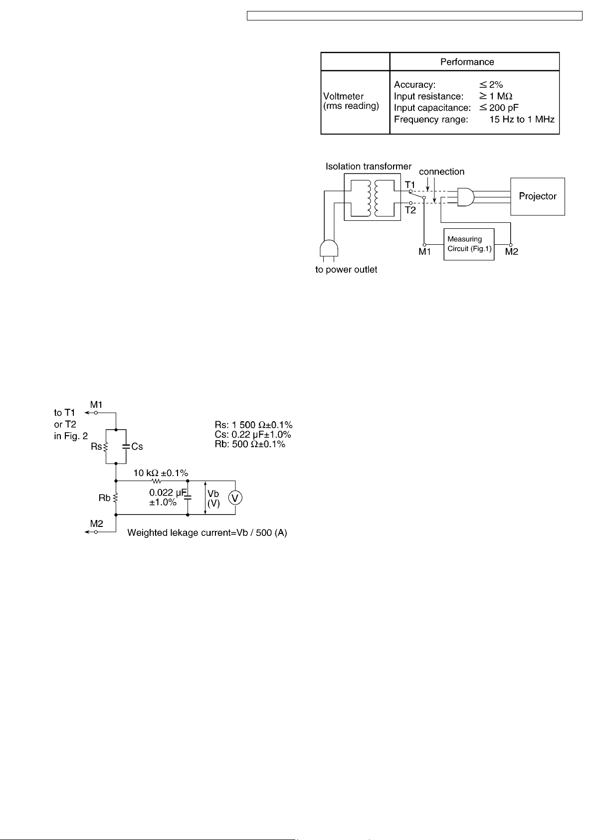
1.2. Leakage Current Check
1. Prepare the measuring circuit as shown in Fig.1.
Be sure to use a voltmeter having the performance
described in Table 1.
Table 1
Fig. 2
2. Assemble the circuit as shown in Fig. 2. Plug the power
cord in a power outlet.
3. Connect M1 to T1 according to Fig. 2 and measure the
voltage.
4. Change the connection of M1 from T1 to T2 and measure
the voltage again.
5. The voltmeter must read 0.375 V or lower in both of steps
3 and 4. This means that the current must be 0.75 mA or
less.
6. If the reading is out of the above standard, the projector
must be repaired and rechecked before returning to the
customer because of a possibility of an electric shock.
Fig. 1
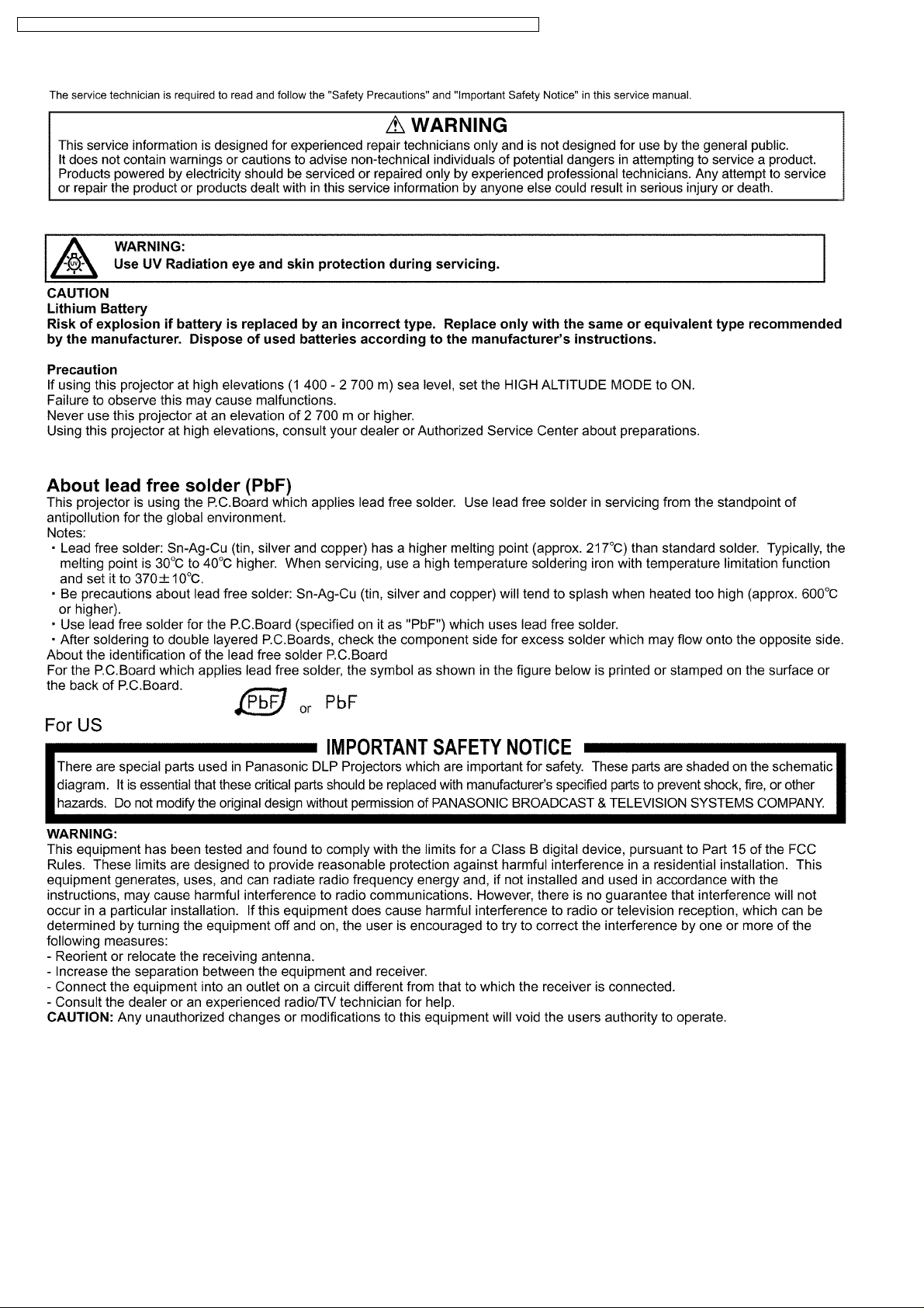
1.3. UV Precaution and UHM Lamp
Precautions
· Be sure to unplug the power cord from the power outlet
when replacing the lamp.
· Because the lamp reaches a very high temperature during
its operation, wait until it cools completely when replacing
the Lamp Unit.
· The lamp emits small amounts of UV-radiation, avoid directeye contact with the light.
· The lamp unit has high internal pressure. If improperly
handled, explosion might result.
5
PT-DZ6710U / PT-DZ6710E / PT-DZ6700U / PT-DZ6700E / PT-DW6300US / PT-DW6300ES / PT-D6000US / PT-D6000ES
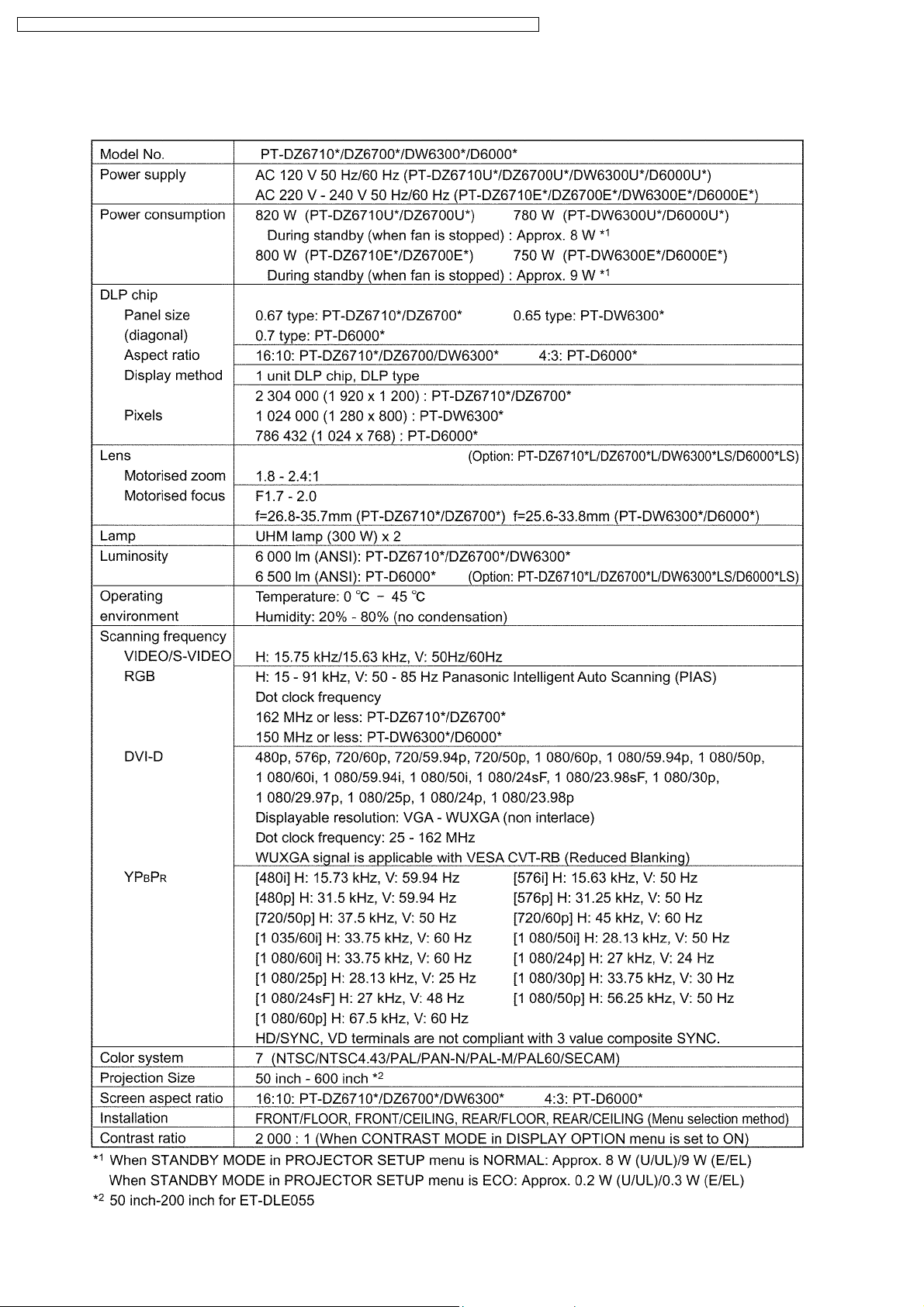
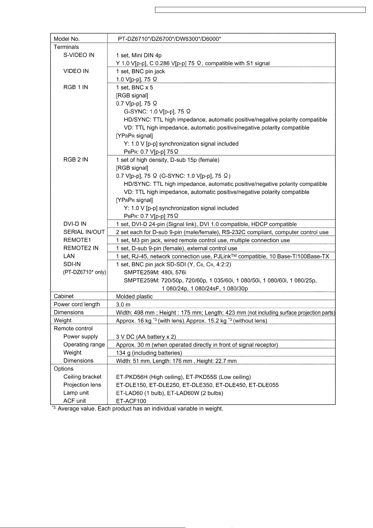
2 Specifications
6
PT-DZ6710U / PT-DZ6710E / PT-DZ6700U / PT-DZ6700E / PT-DW6300US / PT-DW6300ES / PT-D6000US / PT-D6000ES
7
PT-DZ6710U / PT-DZ6710E / PT-DZ6700U / PT-DZ6700E / PT-DW6300US / PT-DW6300ES / PT-D6000US / PT-D6000ES
3 Function for Safety
3.1. Interlock Function
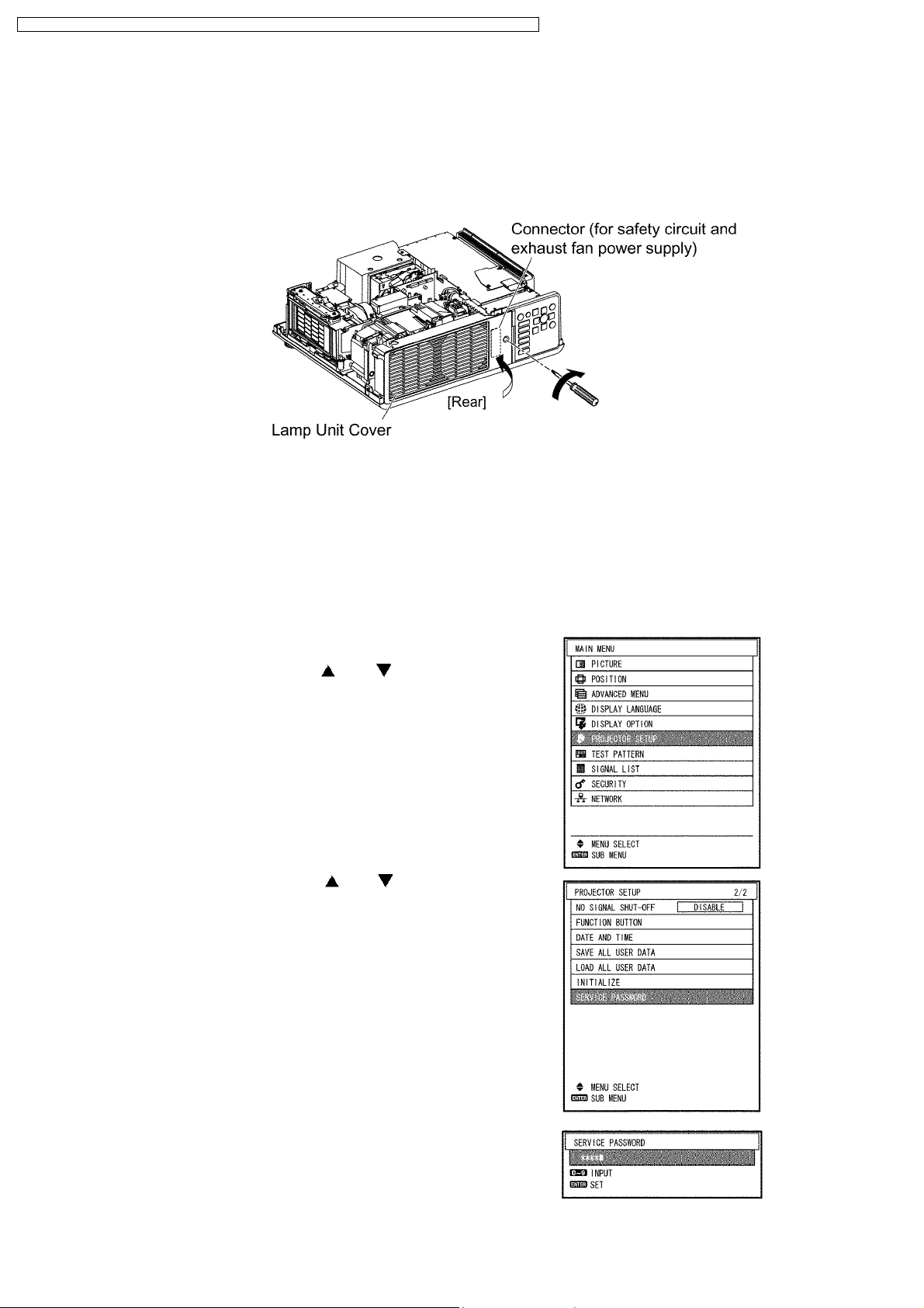
To ensure safety, the protection circuit of the main unit functions, and this projector becomes operation halt condition (a part of
circuit is energizing) when the lamp unit cover is removed or installed incorrectly.
When servicing, install the lamp unit cover in former position when energizing with the upper case removed.
(Be careful enough for safety.)
4 Serviceman Mode
This projector has Serviceman Mode in addition to standard on-screen menus (User Mode).
4.1. Setting to Serviceman Mode
(1) Press the MENU button.
The MAIN MENU screen will appear.
(2) Select “PROJECTOR SETUP” using the or buttons and
press the ENTER button.
The PROJECTOR SETUP screen will appear.
(3) Select “SERVICE PASSWORD” using the or buttons and
press the ENTER button.
The SERVICE PASSWORD screen will appear.
(4) Input the password "1565" by remote control and press the ENTER
button.
Note:
· Asterisk (*) will appear for the password numbers.
8
PT-DZ6710U / PT-DZ6710E / PT-DZ6700U / PT-DZ6700E / PT-DW6300US / PT-DW6300ES / PT-D6000US / PT-D6000ES
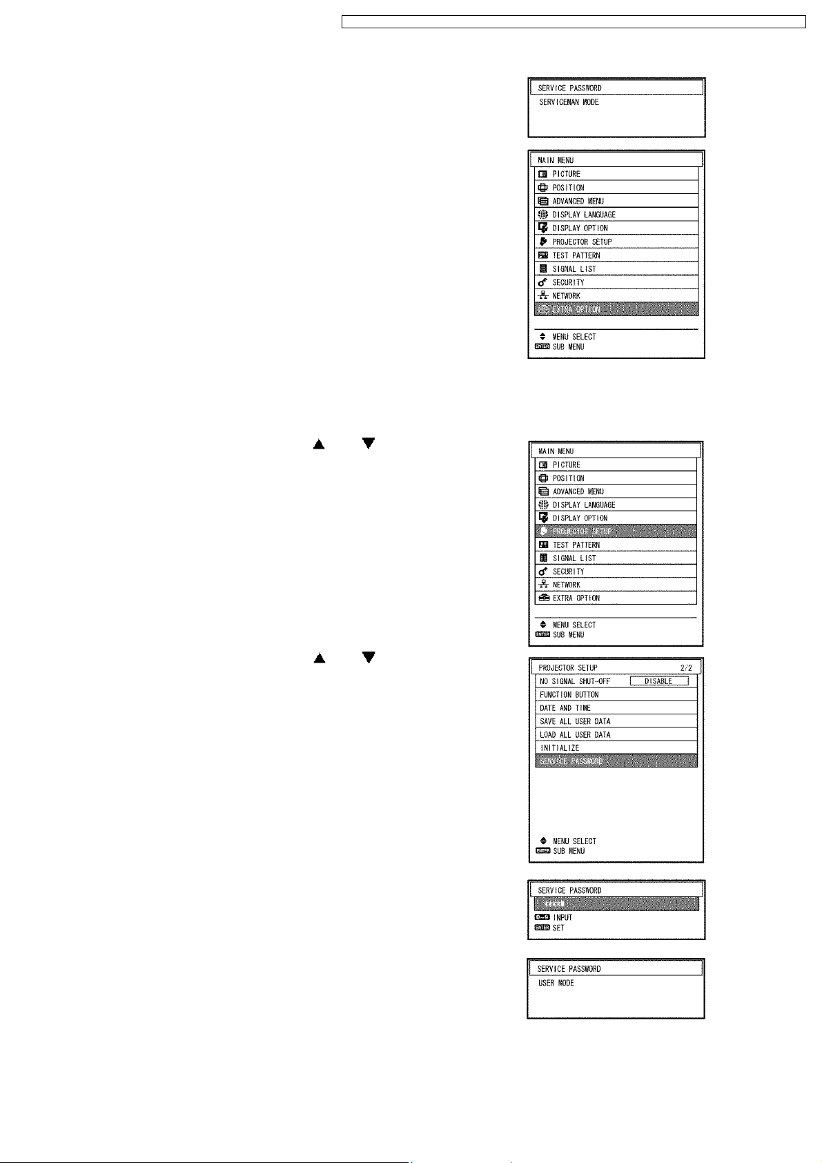
(5) Press the MENU button.
"SERVICEMAN MODE" (MAIN MENU) will be displayed.
4.2. Resetting to User Mode
(1) Press the MENU button.
The MAIN MENU screen will appear.
(2) Select “PROJECTOR SETUP” using the or buttons and
press the ENTER button.
The PROJECTOR SETUP screen will appear.
(3) Select SERVICE PASSWORD using the or buttons and
press the ENTER button.
The SERVICE PASSWORD screen will appear.
(4) Input the password "0000" by remote control and press the ENTER
button.
Note:
· Asterisk (*) will appear for the password numbers.
(5) Press the MENU button.
"USER MODE" (MAIN MENU) will be displayed.
9
PT-DZ6710U / PT-DZ6710E / PT-DZ6700U / PT-DZ6700E / PT-DW6300US / PT-DW6300ES / PT-D6000US / PT-D6000ES
4.3. Functions in Serviceman Mode
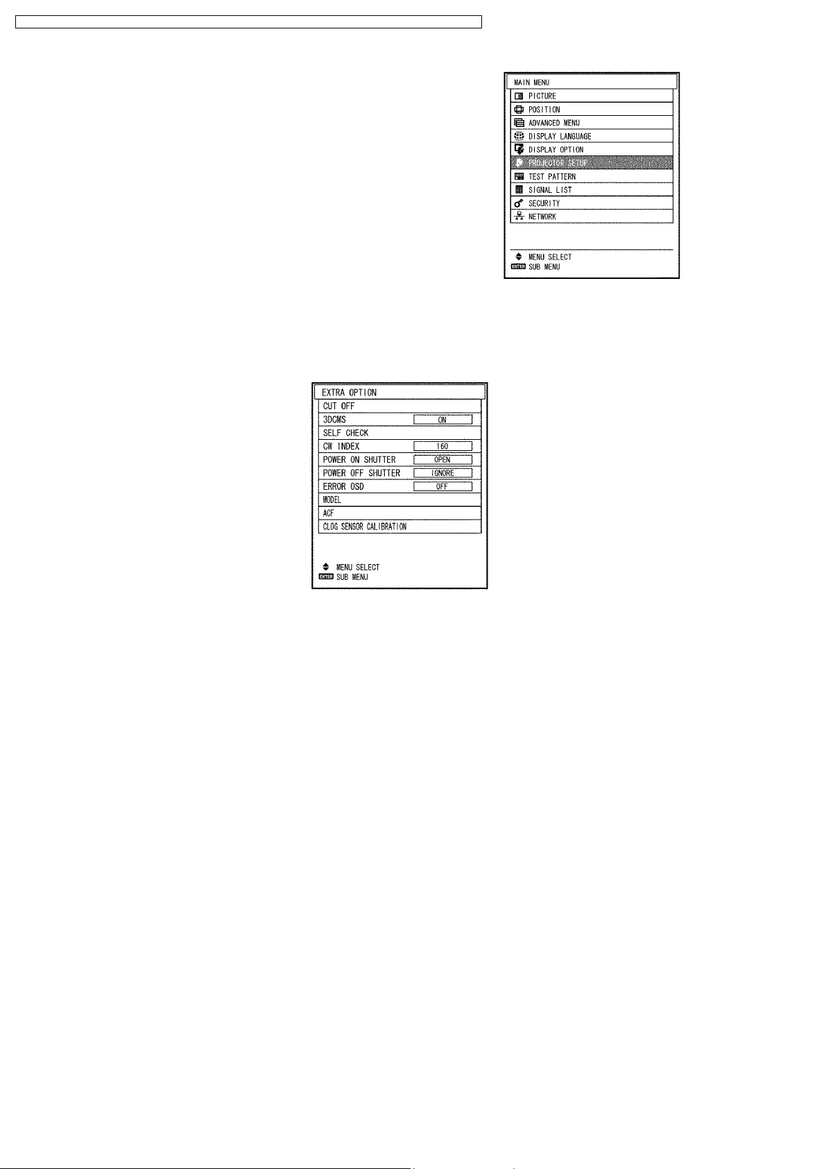
4.3.1. EXTRA OPTION
"EXTRA OPTION" is added to the MENU.
1. CUT OFF
Sets the display ON/OFF for each color (R, G, B).
2. 3DCMS
Sets ON (Valid) / OFF (Invalid) of 3DCMS.
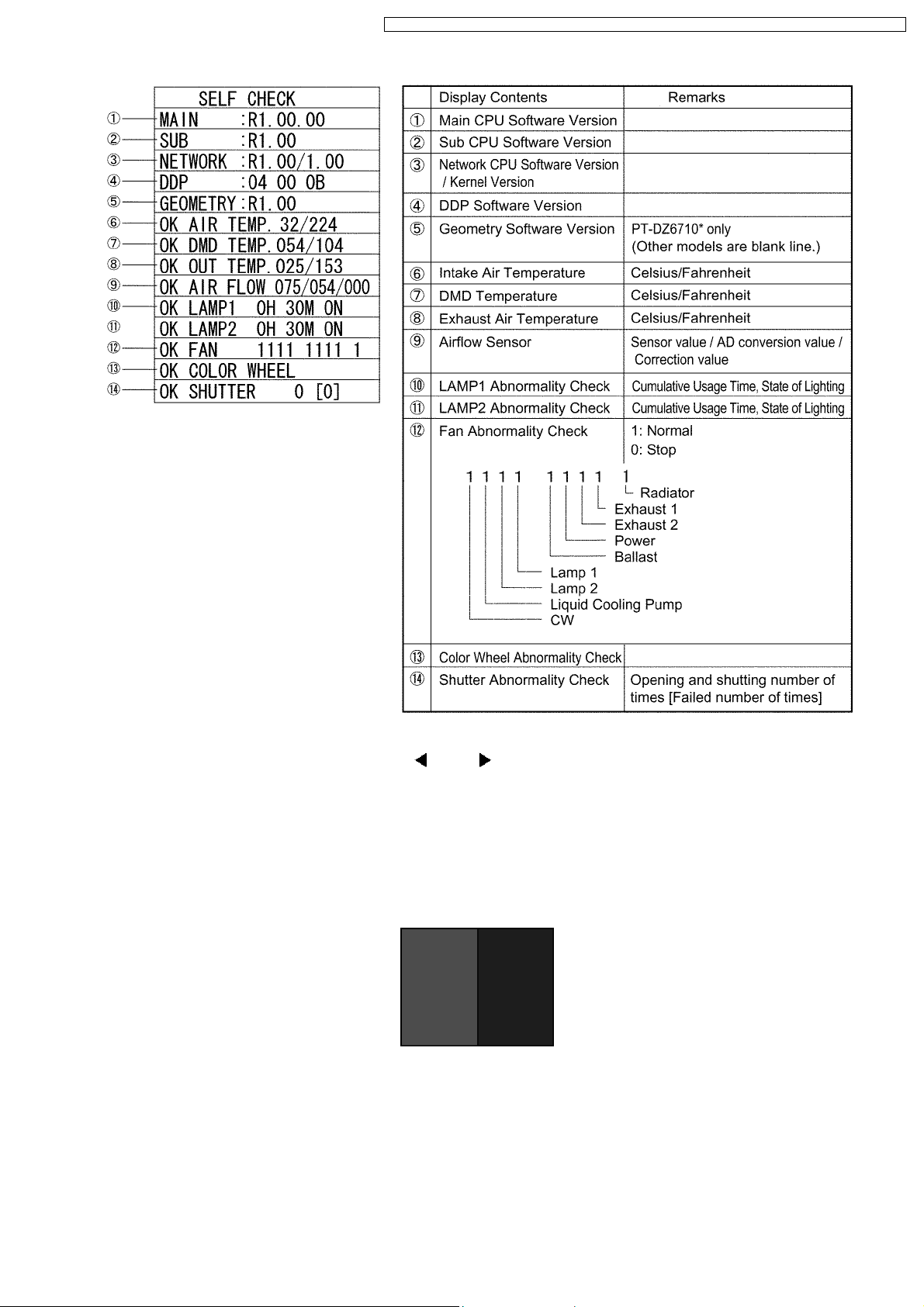
3. SELF CHECK
Displays SELF CHECK.
10
PT-DZ6710U / PT-DZ6710E / PT-DZ6700U / PT-DZ6700E / PT-DW6300US / PT-DW6300ES / PT-D6000US / PT-D6000ES
4. CW INDEX
When the color wheel is replaced, adjusts it with
and buttons.
a. Display the test pattern (Red & Blue pattern).
b. Confirm whether there is a horizontal line.
c. If a horizontal line is in the red area, decrease CW INDEX setting value by 1, and record the value where the horizontal line
(in both red area and blue area) disappears. (The recorded value is assumed to "A".)
d. If a horizontal line is in the blue area, increase CW INDEX setting value by 1, and record the value where the horizontal line
(in both red area and blue area) disappears. (The recorded value is assumed to "B".)
e. Set the mean value (omission below decimal point) of "A" and "B" to the CW INDEX setting value.
5. POWERONSHUTTER
· OPEN: Opens the shutter when power ON.
· CLOSE: Closes the shutter when power ON.
6. POWER OFF SHUTTER
· IGNORE: Does not control the shutter when power OFF.
· OPEN: Opens the shutter when power OFF.
· CLOSE: Closes the shutter when power OFF.
11
PT-DZ6710U / PT-DZ6710E / PT-DZ6700U / PT-DZ6700E / PT-DW6300US / PT-DW6300ES / PT-D6000US / PT-D6000ES
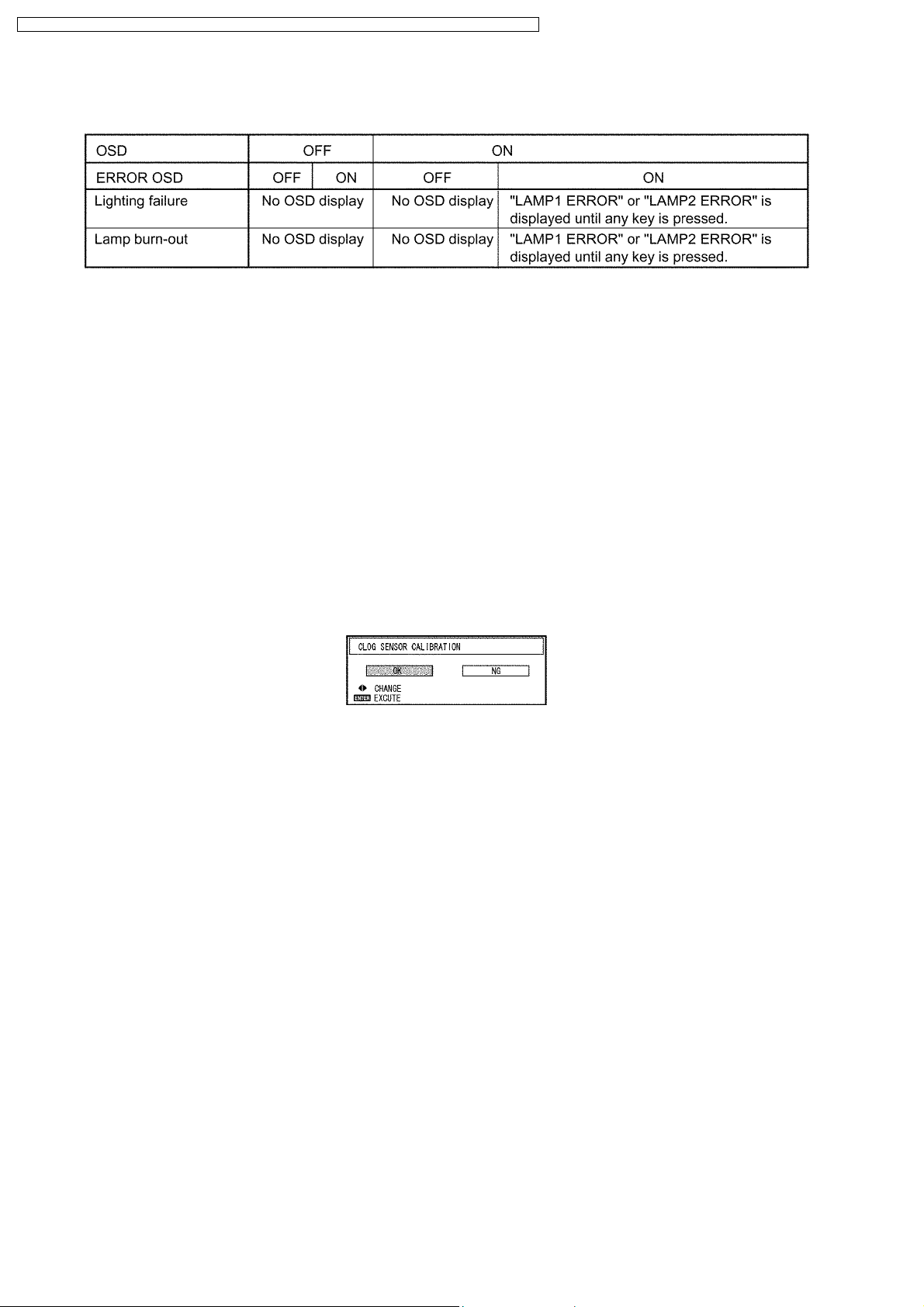
7. ERROR OSD
Displays the lamp status with OSD when you do not see the status LED lights because the rear projection, etc.
8. MODEL
Set it when the A-P.C.Board is replaced.
· If replacing A-P.C.Board (assembly), set MODEL.
* Never set it to a model name different from the model that installs the new A-P.C.Board. If a different model name is set,
it becomes impossible to output normal pictures after the next startup.
* When a new A-P.C.Board is installed without maintenance of adjustment data, it is required to adjust the color wheel.
9. ACF
Executes ACF setting/operation.
· FILTER SETUP: Sets the interval time of automatic rewinding of the filter.
· ROLL: Rewinds the filter once compulsorily.
10. CLOG SENSOR CALIBRATION
Execute the sensor calibration when EEPROM (IC3103 or IC3104) / A-P.C.Board or Airflow sensor (CF1302) is replaced.
* Make the main unit to the assembled state without fail, set the projector to the floor installation, and calibrate.
* If the projector installed at an elevation of 1 400 m or higher sea level, be sure to set the HIGH ALTITUDE MODE sub-menu
in PROJECTOR SETUP menu to ON, and attempt the calibration.
When OK is selected and ENTER button is pressed, the calibration is executed.
· When the calibration is started, the screen becomes whole magenta.
· While calibrating, all lamps will light (DUAL mode).
· Do not switch OFF the projector while calibrating.
· When the magenta screen will disappear in approx. 15 minutes and it returns to the normal screen, the calibration is
completed.
· Turn the POWER switch OFF and turn ON it again, then confirm whether to operate normally.
4.3.2. Ye MODULATE Addition
When the PICTURE MODE menu is displayed, it is enabled to be adjusted with the ENTER button.
· ON: Validates Ye MODULATE function.
· OFF: Invalidates Ye MODULATE function.
4.3.3. ADVANCED MENU Addition
The following 4 items are added to the ADVANCED MENU.
1. FRAME LOCK
When the input signal is RGB, FRAME LOCK is added.
2. 480i SD
When non-standard signal of 480i/576i is inputted (AV amplifier, etc.), synchronization might be disordered according to
connected equipment. In this case, set 480i SD to ON.
3. 480p OS
When 480p/576p is received, aliasing noise (longitudinal striated beat noise) might be generated according to connected
equipment. In this case, set 480p OS to ON. However, the resolution decreases a little.
12

PT-DZ6710U / PT-DZ6710E / PT-DZ6700U / PT-DZ6700E / PT-DW6300US / PT-DW6300ES / PT-D6000US / PT-D6000ES
4. HPLL
When non-standard signal of VIDEO/S-VIDEO is inputted (VCR, VHD, etc.), horizontal synchronization might be disordered
according to connected equipment. In this case, set HPLL to OFF.
4.3.4. STATUS Addition
The following items are added to the STATUS sub-menu in PROJECTOR SETUP menu.
1. APPROXIMATE TIME
Prediction remainder time of the filter in ACF
2. FPGA VERSION
FPGA software version
3. DDP VERSION
DDP software version
4. BALLAST VERSION
Ballast software version
5. GEOMETRY VERSION
Geometry software version (PT-DZ6710* only)
6. LAMP1 ON
Number of times LAMP1 has been lit [Failure number of times]
7. LAMP2 ON
Number of times LAMP2 has been lit [Failure number of times]
8. SHUTTER
Opening and shutting number of times [Failed number of times]
9. TEMP(°C)
Intake air temperature / Exhaust air temperature / Optical module temperature
10. AIR FLOW
Sensor value / AD conversion value
11. VOLT
Voltage of LAMP1/LAMP2
12. POWER
Power fan status (Rotational speed)
13. OUT1
Exhaust 1 fan status (Rotational speed)
14. OUT2
Exhaust 2 fan status (Rotational speed)
15. LAMP1
Lamp 1 fan status (Rotational speed)
16. LAMP2
Lamp 2 fan status (Rotational speed)
17. BALLAST
Ballast fan status (Rotational speed)
18. RADIATOR
Radiator fan status (Rotational speed)
19. CW
CW fan status (Rotational speed)
20. LIQU ID
Liquid cooling pump fan status (Rotational speed)
4.3.5. Shutter Counter Reset
SHUTTER COUNTER is added to the INITIALIZE sub-menu in PROJECTOR SETUP menu.
· The shutter counter can be initialized.
13
PT-DZ6710U / PT-DZ6710E / PT-DZ6700U / PT-DZ6700E / PT-DW6300US / PT-DW6300ES / PT-D6000US / PT-D6000ES
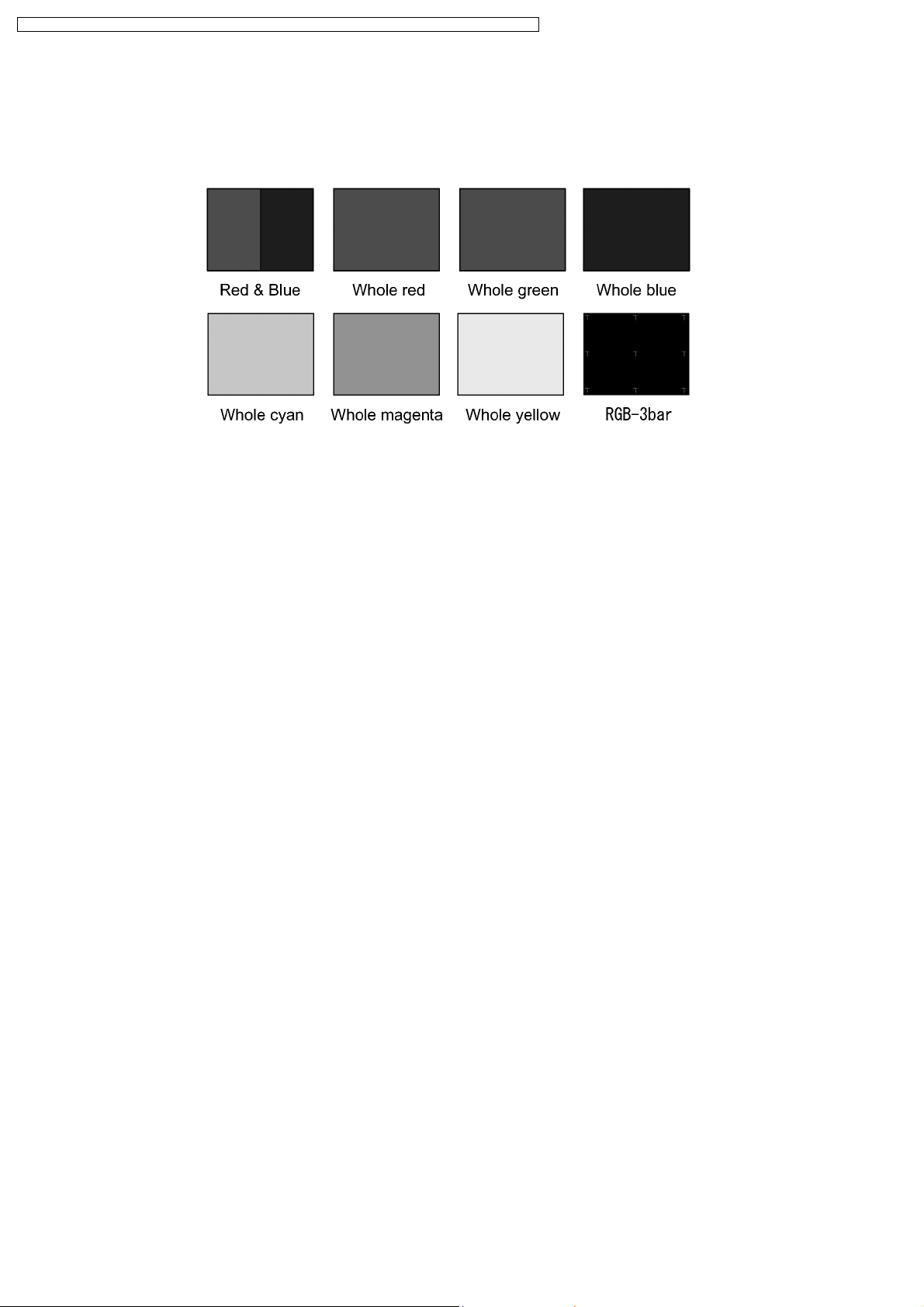
4.3.6. Test Pattern Addition
"Red & Blue", "Whole red", "Whole green", "Whole blue", "Whole cyan", "Whole magenta", "Whole yellow" and "RGB-3bar"
patterns are added to TEST PATTERN.
"Red & Blue" is used for CW INDEX adjustment.
14
PT-DZ6710U / PT-DZ6710E / PT-DZ6700U / PT-DZ6700E / PT-DW6300US / PT-DW6300ES / PT-D6000US / PT-D6000ES
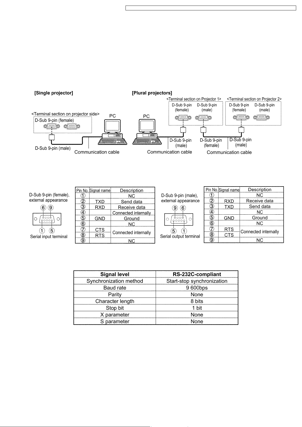
5 External Controls
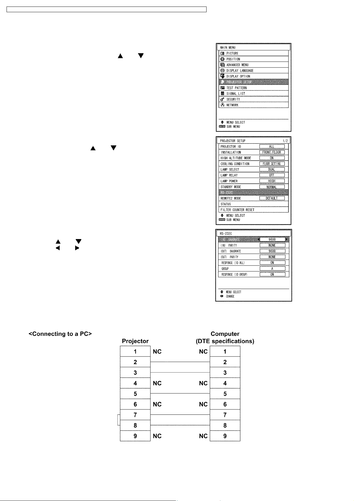
5.1. Control through Serial terminal (SERIAL)
SERIAL terminals which are on the side of the projector conform to RS-232C standard. This projector can be controlled by a PC
which is connected as shown below. Also SERIAL OUT terminal is provided to enable plural projector control.
For controlling this projector by a PC, requires communication software on the market, and inputs control commands according to
5.1.3. "Communication Condition (Factory Settings)" and Basic Format (Refer to 5.3. "Control Commands").
5.1.1. Examples of Connection
5.1.2. Pin Assignments and Signal Names
5.1.3. Communication Condition (Factory Settings)
15
PT-DZ6710U / PT-DZ6710E / PT-DZ6700U / PT-DZ6700E / PT-DW6300US / PT-DW6300ES / PT-D6000US / PT-D6000ES
5.1.4. Procedure of Communication Condition Settings
(1) Press the MENU button.
The MAIN MENU screen will appear.
(2) Select PROJECTOR SETUP using the or button.
(3) Press the ENTER button.
The PROJECTOR SETUP screen will appear.
(4) Select RS-232C using the or button.
(5) Press the ENTER button.
The RS-232C screen will appear.
(6) Press the or button to select communicat i on settings.
(7) Press the or button to confirm the setting..
(8) Press the MENU button three times.
The on-screen indications disappear, and the system returns to the
normal screen.
5.1.5. Cable Specifications
16
PT-DZ6710U / PT-DZ6710E / PT-DZ6700U / PT-DZ6700E / PT-DW6300US / PT-DW6300ES / PT-D6000US / PT-D6000ES
5.2. Control through LAN
Connection and the method of command transmission are different according to the mode (the setting of Admin password on WEB
CONTROL). Control according to the procedure in 5.2.1. on the protection mode (the password is set), and according to the
procedure in 5.2.2. on the unprotected mode (the password is not set).
Refer to 5.3. "Control Commands" for control commands because it is common in the case of Control through Serial terminal
(SERIAL).
5.2.1. When WEB CONTROL Admin Password is set (Protection Mode)
5.2.1.1. Connection
1. Access IP address and the port number (default = 1024) of the projector, then connect to the projector with them.
IP address and the port number can be accessed from the menu of the projector.
· IP address: MAIN MENU → NETWORK → NETWORK STATUS
· Port number: MAIN MENU → NETWORK → NETWORK CONTROL → COMMAND PORT
2. Receive a response message.
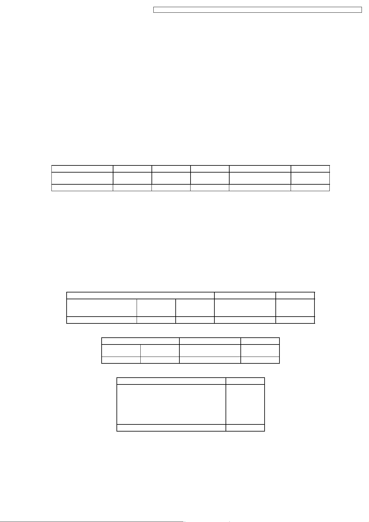
Response Message
Data section Space Mode Space Random characters End character
"NTCONTROL"
(ASCII character string)
9bytes 1byte 1byte 1byte 8bytes 1byte
´´
0x20
´1´
0x31
´´
0x20
"zzzzzzzz"
(Hexadecimal ASCII code)
(CR)
0x0d
Mode: 1 = Protection mode
3. Generate 32 bytes hash value (message digest) from the following data by using the MD5 (Message Digest Algorithm 5).
"xxxxxx:yyyyy:zzzzzzzz"
· xxxxxx: Administrator authority user-name on WEB CONTROL [default = "admin1"]
· yyyyy: Password corresponding to above-mentioned user-name (admin1) [default = "panasonic"]
· zzzzzzzz: 8 bytes random characters obtained from the response message
· (colon): Separator
5.2.1.2. Method of Command Transmission
Transmits command by the following format.
Transmission Data
Header Data section End character
Hash value
(Refer to the step 3 in
5.2.1.1.)
32 bytes 1byte 1byte Undefined length 1byte
Reception Data
Header Data section End character
´0´
0x30
1byte 1byte Undefined length 1byte
Error Response
"ERR1" Command format error (CR) 0x0d
"ERR2" Out of parameter (CR) 0x0d
"ERR3" Busy or unavailable time (CR) 0x0d
"ERR4" Timeout or unavailable time (CR) 0x0d
"ERR5" Data length error (CR) 0x0d
"ERRA" Invalid password (CR) 0x0d
´0´
0x30
´0´
0x30
Error Message End character
4bytes 1byte
´0´
0x30
Control command
(ASCII character string)
Control command
(ASCII character string)
(CR)
0x0d
(CR)
0x0d
Example 1: Query Power "QPW"
1. Connects to the projector.
IP = 192.168.0.8, Port number = 1024
2. Receives a response.
Response = "NTCONTROL 1 1aa6c14e" + (CR)
"1aa6c14e" = 8 bytes random characters
17

PT-DZ6710U / PT-DZ6710E / PT-DZ6700U / PT-DZ6700E / PT-DW6300US / PT-DW6300ES / PT-D6000US / PT-D6000ES
3. Generates a hash value (message digest) from "admin1:panasonic:1aa6c14e" by using the MD5.
"admin1" = Administrator authority user-name
"panasonic" = Password corresponding to "admin1"
Hash value = "01466bc27ed8c0b7e607471580c55953"
4. Transmits the command.
Transmission data = "01466bc27ed8c0b7e607471580c5595300QPW" + (CR)
5. Receives a response.
Reception data = "00000" + (CR)
6. Disconnects the connection with the projector.
Example 2: Query FILTER INFORMATION - RUNTIME "QFI:0"
1. Connects to the projector.
IP = 192.168.0.8, Port number = 1024
2. Receives a response.
Response = "NTCONTROL 1 0bda3637" + (CR)
"0bda3637" = 8 bytes random characters
3. Generates a hash value (message digest) from "admin1:panasonic:0bda3637" by using the MD5 .
"admin1" = Administrator authority user-name
"panasonic" = Password corresponding to "admin1"
Hash value = "a5bf5df3e35c4802a6cdf21880f69093"
4. Transmits the command.
Transmission data = "a5bf5df3e35c4802a6cdf21880f6909300QFI:0" + (CR)
5. Receives a response.
Reception data = "00 (SP) (SP) 142" + (CR)
6. Disconnects the connection with the projector.
5.2.2. When WEB CONTROL Admin Password is not set (Unprotected Mode)
5.2.2.1. Connection
1. Access IP address and the port number (default = 1024) of the projector, then connect to the projector with them.
IP address and the port number can be accessed from the menu of the projector.
· IP address: MAIN MENU → NETWORK → NETWORK STATUS
· Port number: MAIN MENU → NETWORK → NETWORK CONTROL → COMMAND PORT
2. Receive a response message.
Response Message
Data section Space Mode End character
"NTCONTROL"
(ASCII character string)
9bytes 1byte 1byte 1byte
´´
0x20
´0´
0x30
(CR)
0x0d
Mode: 0 = Unprotected mode
5.2.2.2. Method of Command Transmission
Transmits command by the following format.
Transmission Data
Header Data section End character
´0´
0x30
1byte 1byte Undefined length 1byte
´0´
0x30
Control command
(ASCII character string)
(CR)
0x0d
Reception Data
Header Data section End character
´0´
0x30
1byte 1byte Undefined length 1byte
´0´
0x30
Control command
(ASCII character string)
(CR)
0x0d
18
PT-DZ6710U / PT-DZ6710E / PT-DZ6700U / PT-DZ6700E / PT-DW6300US / PT-DW6300ES / PT-D6000US / PT-D6000ES
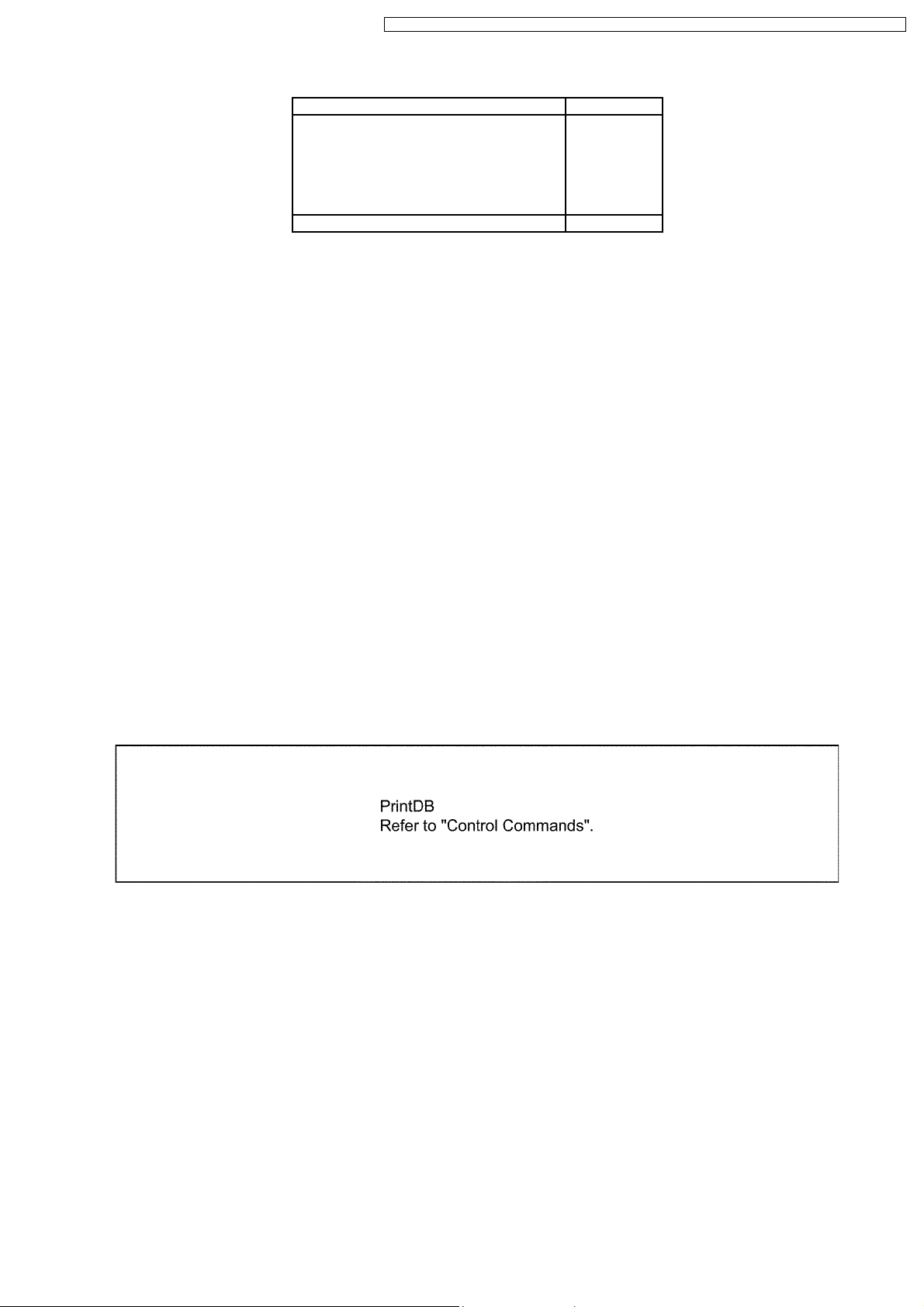
Error Response
Error Message End character
"ERR1" Command format error (CR) 0x0d
"ERR2" Out of parameter (CR) 0x0d
"ERR3" Busy or unavailable time (CR) 0x0d
"ERR4" Timeout or unavailable time (CR) 0x0d
"ERR5" Data length error (CR) 0x0d
"ERRA" Invalid password (CR) 0x0d
4bytes 1byte
Example 1: Query Power "QPW"
1. Connects to the projector.
IP = 192.168.0.8, Port number = 1024
2. Receives a response.
Response = "NTCONTROL 0" + (CR)
3. Transmits the command.
Transmission data = "00QPW" + (CR)
4. Receives a response.
Reception data = "00000" + (CR)
5. Disconnects the connection with the projector.
Example 2: Query FILTER INFORMATION - RUNTIME "QFI:0"
1. Connects to the projector.
IP = 192.168.0.8, Port number = 1024
2. Receives a response.
Response = "NTCONTROL 0" + (CR)
3. Transmits the command.
Transmission data = "00QFI:0" + (CR)
4. Receives a response.
Reception data = "00 (SP) (SP) 142" + (CR)
5. Disconnects the connection with the projector.
5.3. Control commands
19
PT-DZ6710U / PT-DZ6710E / PT-DZ6700U / PT-DZ6700E / PT-DW6300US / PT-DW6300ES / PT-D6000US / PT-D6000ES
6 Using a Wired Remote Control
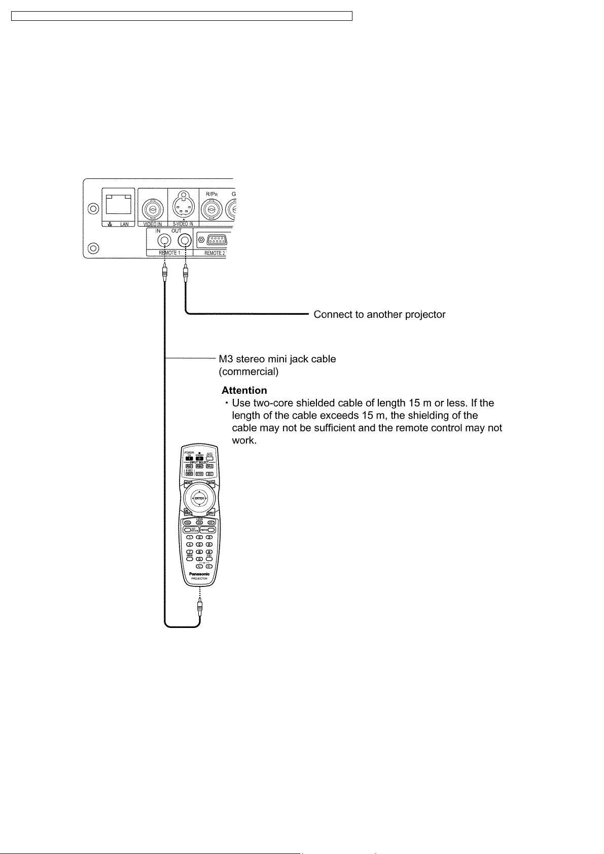
6.1. Connection Example
When multiple projectors are connected as part of the system, connect to units with a M3 stereo mini jack commercial cable to
simultaneously control multiple main units with a single remote control through the REMOTE1 IN/OUT terminal. It is effective to use
the wired remote control in the environment in which an obstacle stands in the light path or where devices are susceptible to outside
light.
6.2. Setting Projector ID Number to Remote Control
Each projector can be assigned a unique 2 digits ID number, and the remote control 2 digits ID number must be set to match the
intended projector. The default setting of the projector ID is ALL. Set the ID of the projector in advance from the menu items.
Procedure of ID setting
1. Press the ID SET button.
Displays the projector ID number on the screen.
2. Within 5 seconds, enter the same number of the required projector by pressing the numeric buttons.
ID number range: 01 - 64
Note:
· Do not press the ID SET button accidentally or carelessly because the ID number on the remote control can be set even
20

PT-DZ6710U / PT-DZ6710E / PT-DZ6700U / PT-DZ6700E / PT-DW6300US / PT-DW6300ES / PT-D6000US / PT-D6000ES
when no projector is around.
· If you do not enter the 2 digits ID number within 5 seconds after the ID SET button has been pressed, the ID will remain
at the number that was set before the ID SET button was pressed.
· Your specified ID will be erased if the batteries of the remote control are left exhausted. When the batteries are replaced,
set the same ID number again.
21

PT-DZ6710U / PT-DZ6710E / PT-DZ6700U / PT-DZ6700E / PT-DW6300US / PT-DW6300ES / PT-D6000US / PT-D6000ES
7 Support for Service
7.1. Supporting Methods
We will support according to the following methods.
Supporting methods Applied parts
Replaced by module or block FM-Module
Ballast-Module (For specified components, supplies them discretely.)
Power-Module
Rod (complete)
Full Reflection Mirror (complete)
Liquid Cooling Unit
Mechanical Shutter Unit
ACF Drive Unit
Replaced by discrete components Other components
Replaced at the manufacturing
department
7.2. Note for Replacement of P.C.Boards
7.2.1. When replacing the A-P.C.Board
· Transfer the data of the original A-P.C.Board to the new A-P.C.Board using the adjustment software and a personal computer.
· If you cannot transfer the data that uses the adjustment software, remove IC3102-IC3104 from the original board and mount
them on the new board.
· Set the model name according to the item 8. "MODEL" in the paragraph 4.3.1. "EXTRA OPTION".
* Consult your dealer or Authorized Service Center for the adjustment software.
DMD block
7.2.2. When replacing the WL-P.C.Board
· When WL-P.C.Board is replaced, explain that to the customer because the MAC (Media Access Control) address for wired LAN
is changed.
7.3. Replacement of the lithium battery on the A-P.C.Board
If the lithium battery will be empty, replace it with a new one (CR2032 or equivalent).
Cautions
· Explosion may occur if replacing the battery with an incorrect one.
· Dispose of used batteries according to the instructions.
8 Cautions for Service
Service or repair the product according to service information on the service manual, etc. so that a fire, injury or electric shock
caused by an improper repair may not occur.
1. Do not modify equipments, components and materials when attempting to service or repair.
2. Do not repair nor connect wires even in case of a part of the disconnection when the wiring unit is supplied as a replacement
parts, replace the wiring unit (complete).
3. For a fasten terminal (push-in type terminal), pull out or insert straightly without twisting it.
4. When the fuse has blown, do not turn on the power supply replacing only the fuse because the secondary disaster of fumes,
fire or other hazards is expected. Turn on the power supply after doing the confirmation and measures of defective causes
(structure and circuit, etc.).
5. After the service or the repair is completed, confirm the operation of the product is normal.
6. Do handling and safekeeping carefully because the user setup information remains in the projector.
8.1. Servicing Methods
· Never unplug the power cord from the outlet, open the circuit breaker, or perform other procedures to cut off the power line
during the operation of any cooling fan.
· Be sure to unplug the power cord from the power outlet before servicing.
Powering off the projector
1. Press the POWER STANDBY "
2. Select "OK" with
or button and press the ENTER button. (or press the POWER STANDBY " " button again.)
" button.
22

PT-DZ6710U / PT-DZ6710E / PT-DZ6700U / PT-DZ6700E / PT-DW6300US / PT-DW6300ES / PT-D6000US / PT-D6000ES
The projection of the image stops, and power indicator of the main unit lights up orange. (The cooling fan keeps running.)
3. Wait until the power indicator of the main unit turns to red (i.e., until the cooling fan stops).
4. Press the "
" marked side of the MAIN POWER switch to remove all power from the projector.
8.2. Light Source Lamp
Strong light is emitted from the projector´s lens. Never look into the lens while the projector is being used. If you look directly into
this light, it can hurt and damage your eyes.
23
PT-DZ6710U / PT-DZ6710E / PT-DZ6700U / PT-DZ6700E / PT-DW6300US / PT-DW6300ES / PT-D6000US / PT-D6000ES
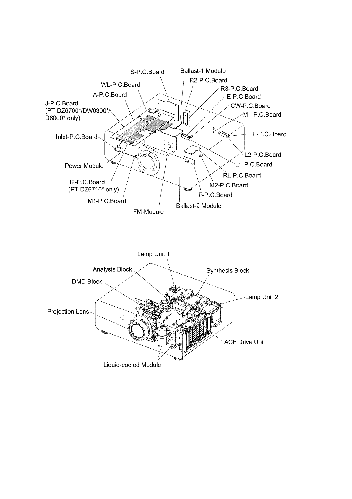
9 Parts Location
9.1. Electrical Parts Location
9.2. Electromechanical Parts Location
24

PT-DZ6710U / PT-DZ6710E / PT-DZ6700U / PT-DZ6700E / PT-DW6300US / PT-DW6300ES / PT-D6000US / PT-D6000ES
10 Disassembly Instructions
10.1. Flowchart for Disassembly
To assemble, reverse the disassembly procedures.
25
PT-DZ6710U / PT-DZ6710E / PT-DZ6700U / PT-DZ6700E / PT-DW6300US / PT-DW6300ES / PT-D6000US / PT-D6000ES
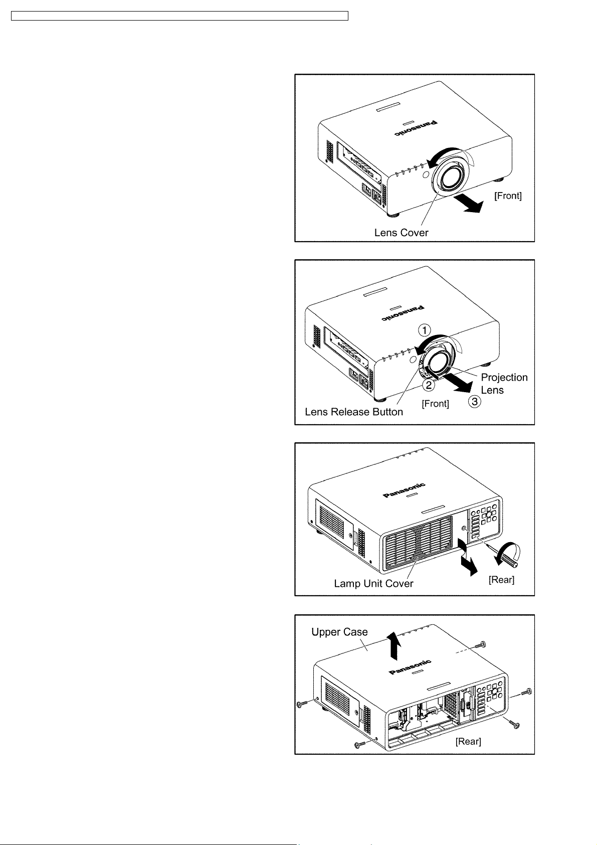
10.2. Removal of Upper Case
(1) Turn the lens cover counterclockwise and remove.
(2) Remove the projection lens.
1. Fully turn the projection Lens counterclockwise.
2. While pressing the lens release button, turn the projection
lens counterclockwise in addition.
3. Remove the projection lens.
(3) Loosen the 1 screw until it idles, then remove the lamp unit
cover.
Note:
· The lamp unit cover is connected to the main unit with
the connector. Be careful when removing it.
(4) Unscrew the 5 screws and remove the upper case.
Note:
· Confirm the lens release button actuates correctly when
you reassemble the upper case as it was.
26
PT-DZ6710U / PT-DZ6710E / PT-DZ6700U / PT-DZ6700E / PT-DW6300US / PT-DW6300ES / PT-D6000US / PT-D6000ES
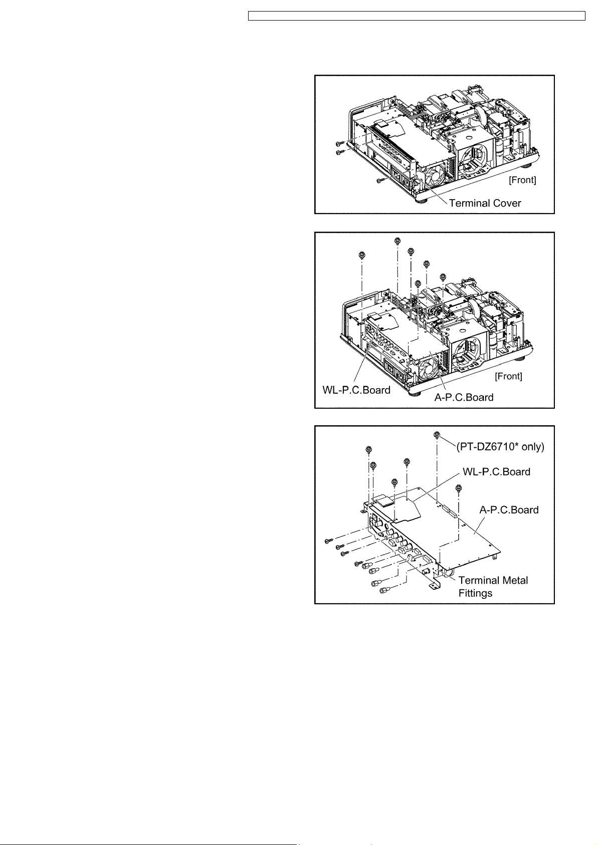
10.3. Removal of A-P.C.Board
(1) Remove the upper case according to the section 10.2. "Removal
of Upper Case".
(2) Unscrew the 3 screws and remove the terminal cover.
(3) Unscrew the 6 screws and remove the A-P.C.Board block.
(4) Unscrew the 3 screws and remove the WL-P.C.Board.
Note:
· The WL-P.C.Board is connected onto the A-P.C.Board
with the connector. Work carefully when removing it.
(5) Disconnect the flexible cable and connectors (only for PT-
DZ6710*) between the A-P.C.Board and J*-P.C.Board (PTDZ6710*: J2-P.C.Board, Other models: J-P.C.Board).
(6) Unscrew the screws (PT-DZ6710*: 11, Other models: 10) and
remove the A-P.C.Board.
27
PT-DZ6710U / PT-DZ6710E / PT-DZ6700U / PT-DZ6700E / PT-DW6300US / PT-DW6300ES / PT-D6000US / PT-D6000ES
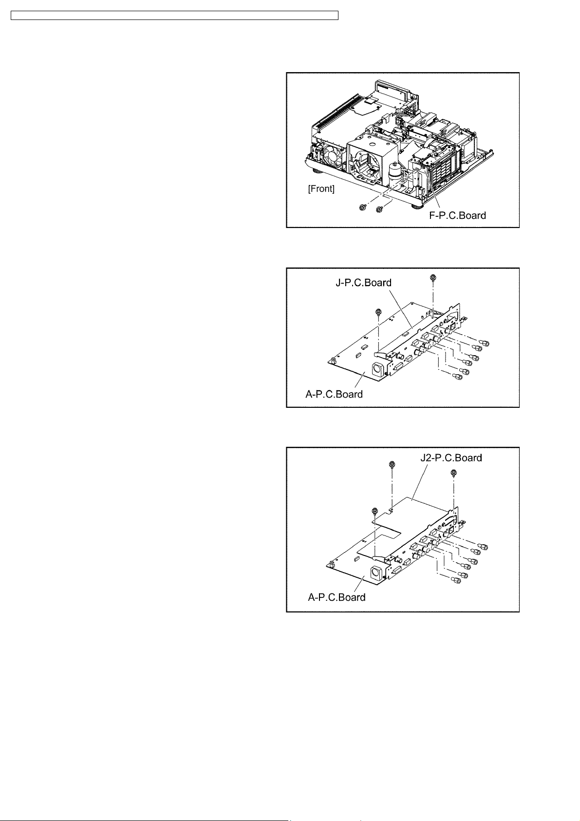
10.4. Removal of F-P.C.Board
(1) Remove the upper case according to the section 10.2. "Removal
of Upper Case".
(2) Unscrew the 2 screws and remove the F-P.C.Board.
10.5. Removal of J-P.C.Board (PT-DZ6700*/DW6300*/D6000*)
(1) Remove the A-P.C.Board block according to the steps 1 through
3 in the section 10.3. "Removal of A-P.C.Board".
(2) Disconnect the flexible cable and connectors between the A-
P.C.Board and J-P.C.Board.
(3) Unscrew the 8 screws and remove the J-P.C.Board.
10.6. Removal of J2-P.C.Board (PT-DZ6710*)
(1) Remove the A-P.C.Board block according to the steps 1 through
3 in the section 10.3. "Removal of A-P.C.Board".
(2) Disconnect the flexible cable and connectors between the A-
P.C.Board and J2-P.C.Board.
(3) Unscrew the 9 screws and remove the J2- P.C.Board.
28
PT-DZ6710U / PT-DZ6710E / PT-DZ6700U / PT-DZ6700E / PT-DW6300US / PT-DW6300ES / PT-D6000US / PT-D6000ES
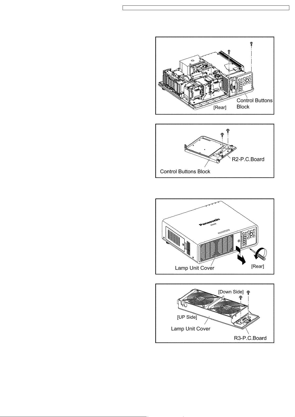
10.7. Removal of R2-P.C.Board
(1) Remove the upper case according to the section 10.2. "Removal
of Upper Case".
(2) Unscrew the 2 screws and remove the Control Buttons Block.
(3) Unscrew the 2 screws and remove the R2-P.C.Board.
10.8. Removal of R3-P.C.Board
(1) Loosen the 1 screw until it idles, then remove the lamp unit cover.
Note:
· The lamp unit cover is connected to the main unit with
the connector. Be careful when removing it.
(2) Unscrew the 2 screws and remove the R3-P.C.Board.
29
PT-DZ6710U / PT-DZ6710E / PT-DZ6700U / PT-DZ6700E / PT-DW6300US / PT-DW6300ES / PT-D6000US / PT-D6000ES
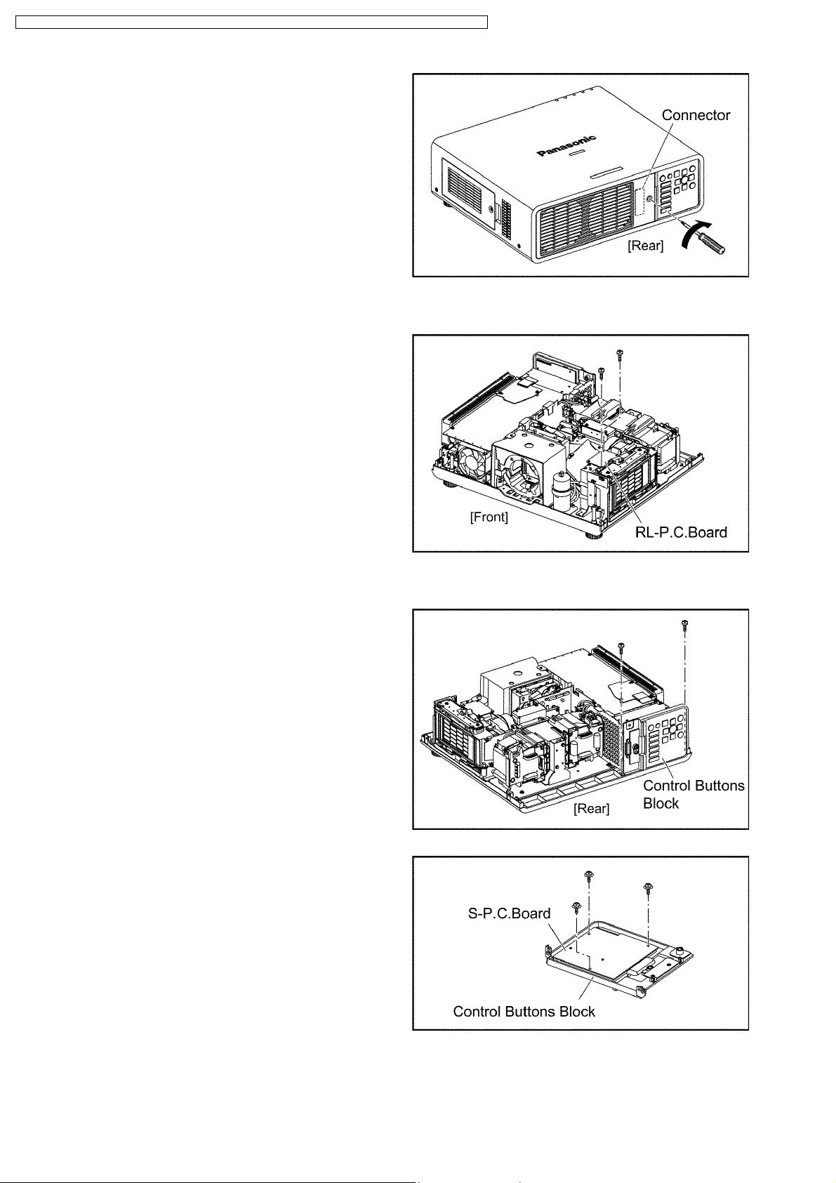
(3)
Note:
· When installing the lamp unit cover, confirm the
connector is connected properly, then tighten the 1
screw.
10.9. Removal of RL-P.C.Board
(1) Remove the upper case according to the section 10.2. "Removal
of Upper Case".
(2) Unscrew the 2 screws and remove the RL-P.C.Board .
10.10. Removal of S-P.C.Board
(1) Remove the upper case according to the section 10.2. "Removal
of Upper Case".
(2) Unscrew the 2 screws and remove the Control Buttons Block.
(3) Unscrew the 3 screws and remove the S-P.C.Board .
30
 Loading...