

Panasonic PT-D5700U, PT-D5700E, PT-D5700UL, PT-D5700EL, PT-DW5100U Service Manual
...
DLP Based Projector
PT-D5700U
PT-D5700E
PT-D5700UL
PT-D5700EL
PT-DW5100U
PT-DW5100E
PT-DW5100UL
ORDER NO. VED0706378C0
D10
PT-DW5100EL
© 2007 Matsushita Electric Industrial Co., Ltd. All
rights reserved. Unauthorized copying and
distribution is a violation of law.
PT-D5700U / PT-D5700E / PT-D5700UL / PT-D5700EL / PT-DW5100U / PT-DW5100E / PT-DW5100UL / PT-DW5100EL
2

PT-D5700U / PT-D5700E / PT-D5700UL / PT-D5700EL / PT-DW5100U / PT-DW5100E / PT-DW5100UL / PT-DW5100EL
CONTENTS
Page Page
1 Safety Precautions 4
1.1. General Guidelines
1.2. Leakage Current Check
1.3. UV Precaution and UHM Lamp Precautions
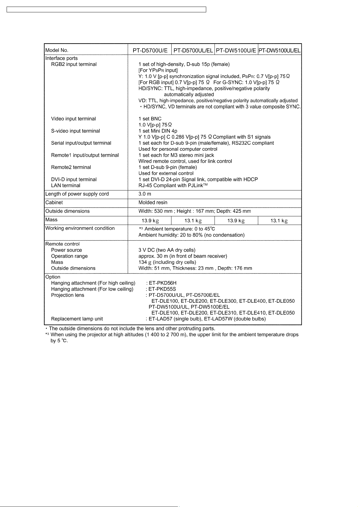
2 Specifications
3 Function for Safety
3.1. Interlock Switch
4 Serviceman Mode
4.1. Setting to Serviceman Mode
4.2. Resetting to User Mode
4.3. Functions in Serviceman Mode
5 Using the Serial Terminals
5.1. Examples of Connection
5.2. Pin Assignments and Signal Names
5.3. Communication Conditions (Factory Setting)
5.4. Procedure of Communication Condition Settings
5.5. Control commands
5.6. Cable specifications
6 Using a Wired Remote Control
6.1. Connection Example
6.2. Setting the Projector ID Number for Remote Control
7 Support for Service
7.1. Supporting Methods
7.2. Note for Replacement of P.C.Boards
7.3. Replacement of the lithium battery on the A-P.C.Board
8 Cautions for Service
8.1. Servicing Methods
8.2. Light Source Lamp
9 Parts Location
9.1. Electrical Parts Location
9.2. Electromechanical Parts Location
10 Replacement of Lamp Unit
10.1. Before replacing the Lamp Unit
10.2. When to replace the Lamp Unit
10.3. Indication of Lamp Monitor
11 Disassembly Instructions
11.1. Flowchart for Disassembly
11.2. Removal of Upper Case
11.3. Removal of A-P.C.Board
11.4. Removal of J-P.C.Board
11.5. Removal of Power Module
13
13
13
13
14
14
15
16
16
16
18
18
18
18
18
18
18
19
19
19
20
20
20
21
22
22
23
23
24
24
11.6. Removal of R-P.C.Board
4
4
4
5
7
7
7
7
8
9
11.7. Removal of S-P.C.Board
11.8. Removal of Ballast-1 and Ballast-2 Modules
11.9. Removal of Lamp Unit
11.10. Removal of Projection Lens
11.11. Removal of Analysis Block
11.12. Removal of Synthesis Mirror
11.13. Removal of Color Wheel Block (Analysis Block)
11.14. Removal of Rod (complete)
11.15. Removal of Full Reflection Mirror (complete)
11.16. Removal of DMD Block (complete)
11.17. Removal of Mechanical Shutter Unit
12 Tr oubleshooting
13 Int erc onnection Block Diagram
13.1. Interconnection Block Diagram (1/2)
13.2. Interconnection Block Diagram (2/2)
14 Block Diagram
14.1. Power Supply
14.2. Signal Processing (1/2)
14.3. Signal Processing (2/2)
14.4. Fan/Motor Drive
15 Schematic Diagram
15.1. A-P.C.Board (1/9)
15.2. A-P.C.Board (2/9)
15.3. A-P.C.Board (3/9)
15.4. A-P.C.Board (4/9)
15.5. A-P.C.Board (5/9)
15.6. A-P.C.Board (6/9)
15.7. A-P.C.Board (7/9)
15.8. A-P.C.Board (8/9)
15.9. A-P.C.Board (9/9)
15.10. R/S-P.C.Board
15.11. J-P.C.Board
16 C irc uit Boards
16.1. A-P.C.Board (Foil Side)
16.2. A-P.C.Board (Component Side)
16.3. J-P.C.Board
17 Te rm inal guide of ICs and tr ansis tors
18 Ex ploded View s
19 Replacement Parts List
25
25
25
28
28
29
30
31
32
33
34
35
36
47
47
48
49
49
50
51
52
53
54
55
56
57
58
59
60
61
62
63
64
65
65
66
67
69
70
74
3
PT-D5700U / PT-D5700E / PT-D5700UL / PT-D5700EL / PT-DW5100U / PT-DW5100E / PT-DW5100UL / PT-DW5100EL
1 Safety Precautions
1.1. General Guidelines
· For continued safety, no modification of any circuit must be
attempted.
· Unplug the power cord from the power outlet before
disassembling this projector.
· Use correctly the supplied power cord and must ground it.
· It is advisable to use an isolation transformer in the AC
power line before the service.
· Be careful not to touch the rotation part (cooling fan, etc.) of
this projector when you service with the upper case
removed and the power supply turned ON.
· Observe the original lead dress during the service. If a short
circuit is found, replace all the parts overheated or
damaged by the short circuit.
· After the service, all the protective devices such as
insulation barriers, insulation papers, shields, and isolation
R-C combinations must be properly installed.
· After the service, check the leakage current to prevent the
customer from getting an electric shock.
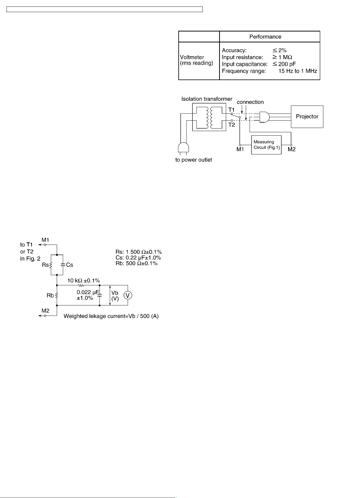
1.2. Leakage Current Check
1. Prepare the measuring circuit as shown in Fig.1.
Be sure to use a voltmeter having the performance
described in Table 1.
2. Assemble the circuit as shown in Fig. 2. Plug the power
cord in a power outlet.
3. Connect M1 to T1 according to Fig. 2 and measure the
voltage.
4. Change the connection of M1 from T1 to T2 and measure
the voltage again.
5. The voltmeter must read 0.375 V or lower in both of steps
3 and 4. This means that the current must be 0.75 mA or
less.
6. If the reading is out of the above standard, the projector
must be repaired and rechecked before returning to the
customer because of a possibility of an electric shock.
Table 1
Fig. 2
Fig. 1
1.3. UV Precaution and UHM Lamp
Precautions
· Be sure to unplug the power cord from the power outlet
when replacing the lamp.
· Because the lamp reaches a very high temperature during
its operation, wait until it cools completely when replacing
the Lamp Unit.
· The lamp emits small amounts of UV-radiation, avoid directeye contact with the light.
· The lamp unit has high internal pressure. If improperly
handled, explosion might result.
4
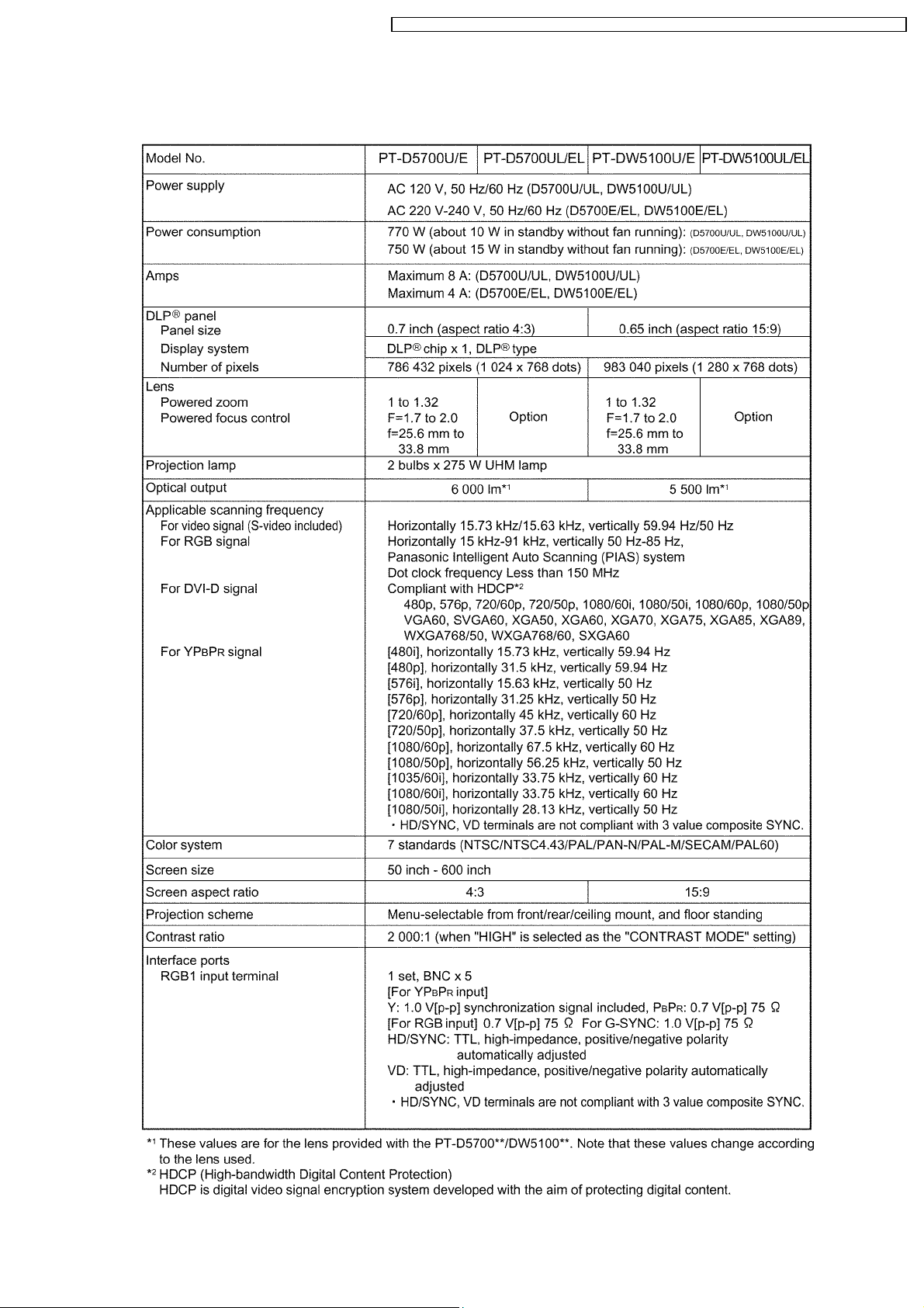
2 Specifications
PT-D5700U / PT-D5700E / PT-D5700UL / PT-D5700EL / PT-DW5100U / PT-DW5100E / PT-DW5100UL / PT-DW5100EL
5
PT-D5700U / PT-D5700E / PT-D5700UL / PT-D5700EL / PT-DW5100U / PT-DW5100E / PT-DW5100UL / PT-DW5100EL
6
PT-D5700U / PT-D5700E / PT-D5700UL / PT-D5700EL / PT-DW5100U / PT-DW5100E / PT-DW5100UL / PT-DW5100EL
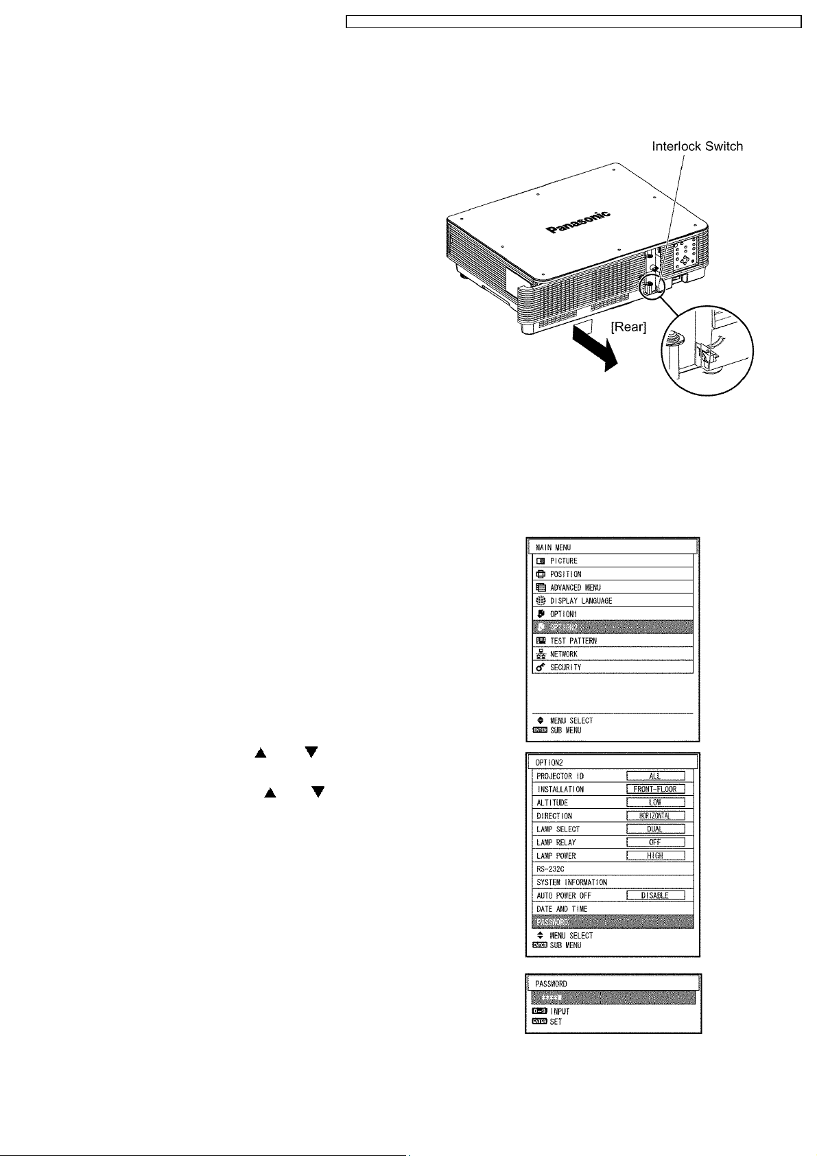
3 Function for Safety
3.1. Interlock Switch
To ensure safety, the protection circuit of the main unit functions, and
this projector becomes operation halt condition (a part of circuit is
energizing) when the l amp unit cover is removed or installed incorrectly.
4 Serviceman Mode
This projector has Serviceman Mode in addition to standard on-screen menus (User Mode).
4.1. Setting to Serviceman Mode
(1) Press the MENU button.
The MAIN MENU screen will appear.
(2) Select “OPTION2” using the or buttons and press the
ENTER button.
The OPTION2 screen will appear.
(3) Select “PASSWORD” using the or buttons and press the
ENTER button.
The PASSWORD screen will appear.
(4) Input the password "1565" by remote control unit and press the
ENTER button.
Note:
· Asterisk (*) will appear for the password numbers.
7
PT-D5700U / PT-D5700E / PT-D5700UL / PT-D5700EL / PT-DW5100U / PT-DW5100E / PT-DW5100UL / PT-DW5100EL
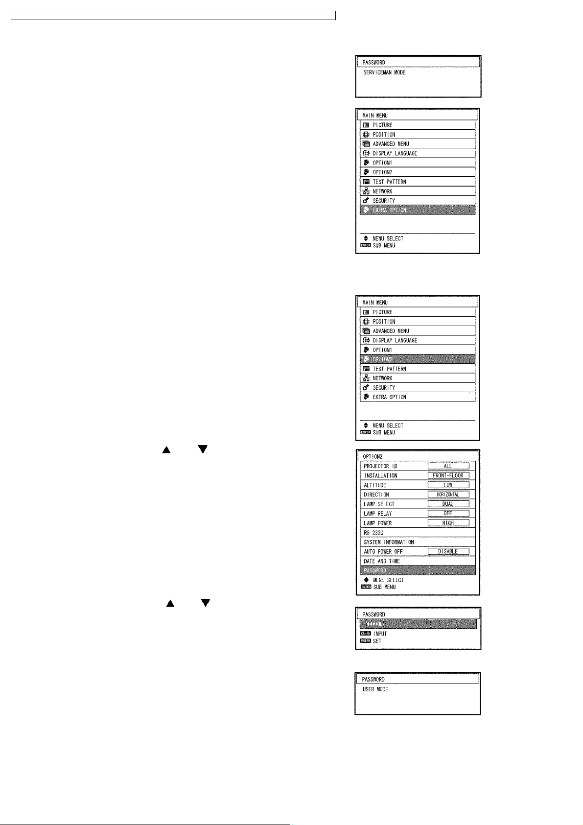
(5) Press the MENU button.
Note:
· "SERVICEMAN" will appear in a few seconds, then appear the
MENU display as shown in right.
4.2. Resetting to User Mode
(1) Press the MENU button.
The MAIN MENU screen will appear.
(2) Select “OPTION2” using the or buttons and press the
ENTER button.
The OPTION2 screen will appear.
(3) Select PASSWORD using the or buttons and press the
ENTER button.
The PASSWORD screen will appear.
(4) Input the password "0000" by remote control unit and press the
ENTER button.
Note:
· Asterisk (*) will appear for the password numbers.
(5) Press the MENU button.
8
PT-D5700U / PT-D5700E / PT-D5700UL / PT-D5700EL / PT-DW5100U / PT-DW5100E / PT-DW5100UL / PT-DW5100EL
Note:
· "USER" will appear in a few seconds, then appear the MENU
display as shown in right.
4.3. Functions in Serviceman Mode
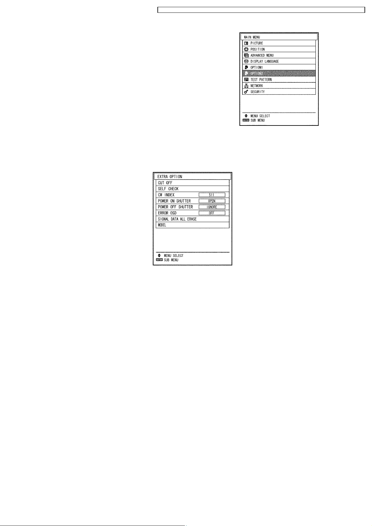
4.3.1. EXTRA OPTION
"EXTRA OPTION" is added to the MENU.
1. CUT OFF
Sets the display ON/OFF for each color (R, G, B).
9
PT-D5700U / PT-D5700E / PT-D5700UL / PT-D5700EL / PT-DW5100U / PT-DW5100E / PT-DW5100UL / PT-DW5100EL
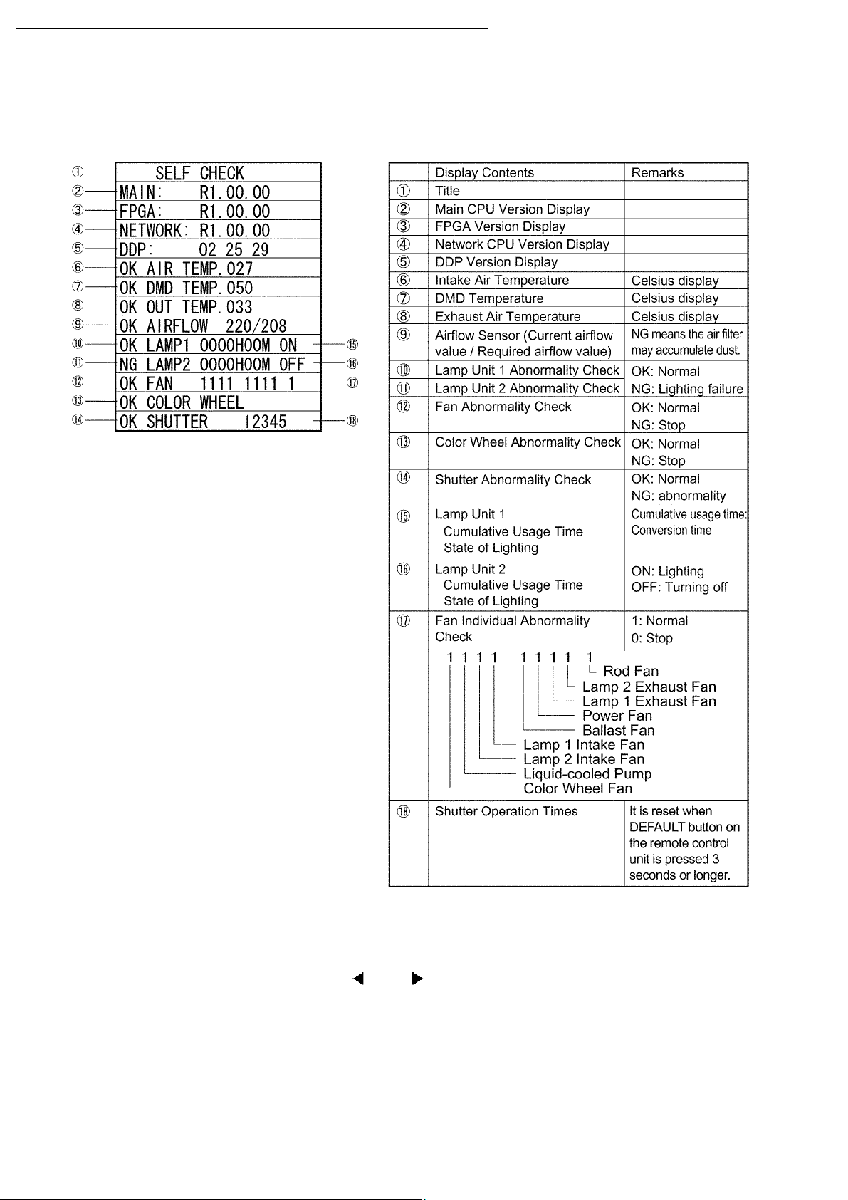
2. SELF CHECK
Displays SELF CHECK.
3. CW INDEX
When the color wheel is replaced, adjusts it with
and buttons.
a. Display the test pattern 9 (Red & Blue pattern).
b. Confirm whether there is a horizontal line.
c. If a horizontal line is in the red area, decrease CW INDEX setting value by 1, and record the value where the horizontal line
(in both red area and blue area) disappears. (The recorded value is assumed to "A".)
d. If a horizontal line is in the blue area, increase CW INDEX setting value by 1, and record the value where the horizontal line
(in both red area and blue area) disappears. (The recorded value is assumed to "B".)
10
PT-D5700U / PT-D5700E / PT-D5700UL / PT-D5700EL / PT-DW5100U / PT-DW5100E / PT-DW5100UL / PT-DW5100EL
e. Set the mean value (omission below decimal point) of "A" and "B" to the CW INDEX setting value.
4. POWERONSHUTTER
· OPEN: Opens the shutter when power ON.
· CLOSE: Closes the shutter when power ON.
5. POWER OFF SHUTTER
· IGNORE: Does not control the shutter when power OFF.
· OPEN: Opens the shutter when power OFF.
· CLOSE: Closes the shutter when power OFF.
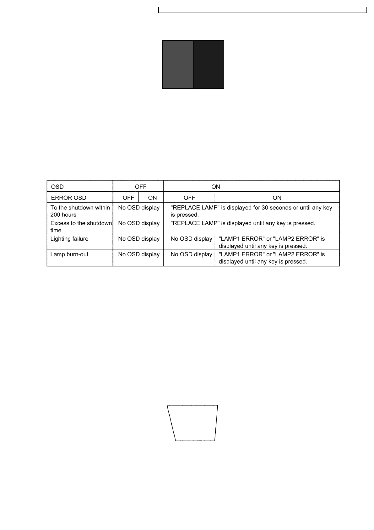
6. ERROR OSD
Displays the lamp status with OSD when you do not see the status LED lights because the rear projection, etc.
7. SIGNAL DATA ALL ERASE
Resets the setting value of each signal to the initial value of the factory shipment.
8. MODEL
Sets the model name.
· Set it when you install a new A-P.C.Board without maintenance (data transfer or IC replacement) of adjustment data etc.
according to the paragraph 7.2.1.
* Never set it to a model name different from the model that installs the new A-P.C.Board. If a different model name is set,
it becomes impossible to output normal pictures after the next startup.
* When a new A-P.C.Board is installed without maintenance of adjustment data, it is required to adjust the color wheel.
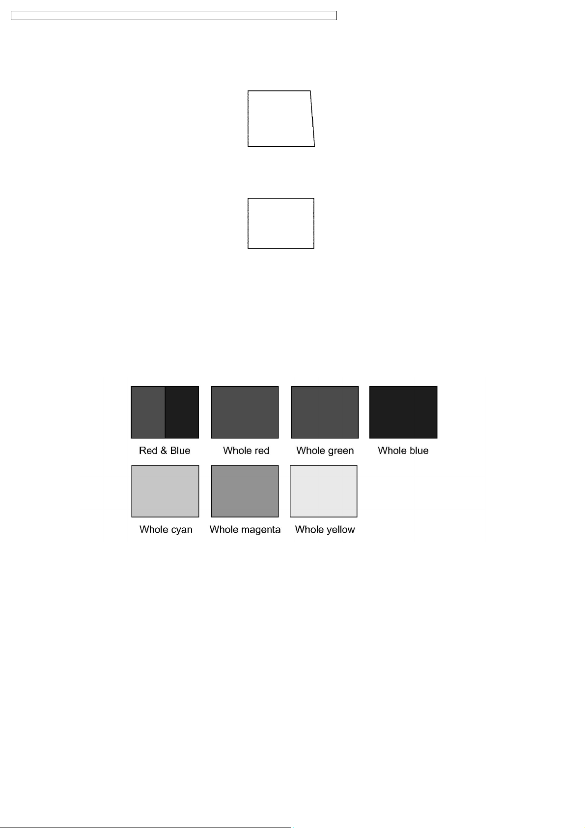
4.3.2. SUB KEYSTONE
"SUB KEYSTONE" is added to KEYSTONE in the "POSITION" menu.
If KEYSTONE and "Lens shift" are used at the same time, the right and left is corrected in the unbalance.
At this time, only the right side can be corrected by SUB KEYSTONE.
11
PT-D5700U / PT-D5700E / PT-D5700UL / PT-D5700EL / PT-DW5100U / PT-DW5100E / PT-DW5100UL / PT-DW5100EL
1. The left side is adjusted straight by KEYSTONE.
2. The right side is adjusted straight by SUB KEYSTONE.
Note:
· SUB KEYSTONE is a supplementary adjustment function and there is no guaranty of completely functioning. Use it
within the range where the trouble such as deforming the shape of the image does not occur.
4.3.3. Test Pattern Addition
"Red & Blue", "Whole red", "Whole green", "Whole blue", "Whole cyan", "Whole magenta" and "Whole yellow" patterns are added
to the test pattern.
"Red & Blue" is used for CW INDEX adjustment.
4.3.4. Ye MODULATE Addition
When the PICTURE MODE menu is displayed, it is enabled to be adjusted with the ENTER button.
· ON: Validates Ye MODULATE function.
· OFF: Invalidates Ye MODULATE function.
4.3.5. FRAME LOCK
When the input signal is RGB, FRAME LOCK is added to the POSITION menu.
4.3.6. ADVANCED MENU Addition
The following 3 items are added to ADVANCED MENU.
1. 480i SD
When non-standard signal of 480i/576i is inputted (AV amplifier, etc.), synchronization might be disordered according to
connected equipment. In this case, set 480i SD to ON.
2. 480p OS
When 480p/576p is received, aliasing noise (longitudinal striated beat noise) might be generated according to connected
equipment. In this case, set 480p OS to ON. However, the resolution decreases a little.
12
PT-D5700U / PT-D5700E / PT-D5700UL / PT-D5700EL / PT-DW5100U / PT-DW5100E / PT-DW5100UL / PT-DW5100EL
3. HPLL
When non-standard signal of VIDEO/S-VIDEO is inputted (VTR, VHD, etc.), horizontal synchronization might be disordered
according to connected equipment. In this case, set HPLL to OFF.
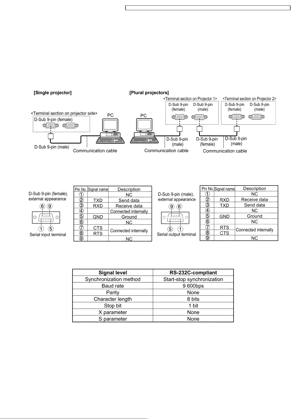
5 Using the Serial Terminals
SERIAL terminals which are on the side-mounted connection terminals conform to RS-232C standard. This projector can be
controlled by a PC which is connected as shown below. Also SERIAL OUT terminal is provided to enable plural projector control.
5.1. Examples of Connection
5.2. Pin Assignments and Signal Names
5.3. Communication Conditions (Factory Setting)
13
PT-D5700U / PT-D5700E / PT-D5700UL / PT-D5700EL / PT-DW5100U / PT-DW5100E / PT-DW5100UL / PT-DW5100EL
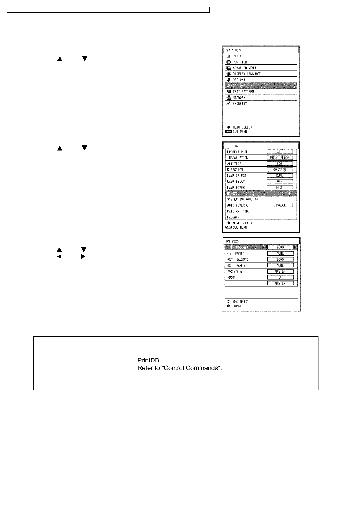
5.4. Procedure of Communication Condition Settings
(1) Press the MENU button.
The MAIN MENU screen will be displayed.
(2) Press the and buttons to select “OPTION2”.
(3) Press the ENTER button.
(4) Press the and buttons to select “RS-232C”.
(5) Press the ENTER button.
The RS-232C screen will be displayed.
(6) Press the and buttons to select communication conditions.
(7) Press the and buttons to confirm the setting..
(8) Press the MENU button three times.
The on-screen indications disappear, and the system returns to the
normal screen.
5.5. Control commands
14
PT-D5700U / PT-D5700E / PT-D5700UL / PT-D5700EL / PT-DW5100U / PT-DW5100E / PT-DW5100UL / PT-DW5100EL
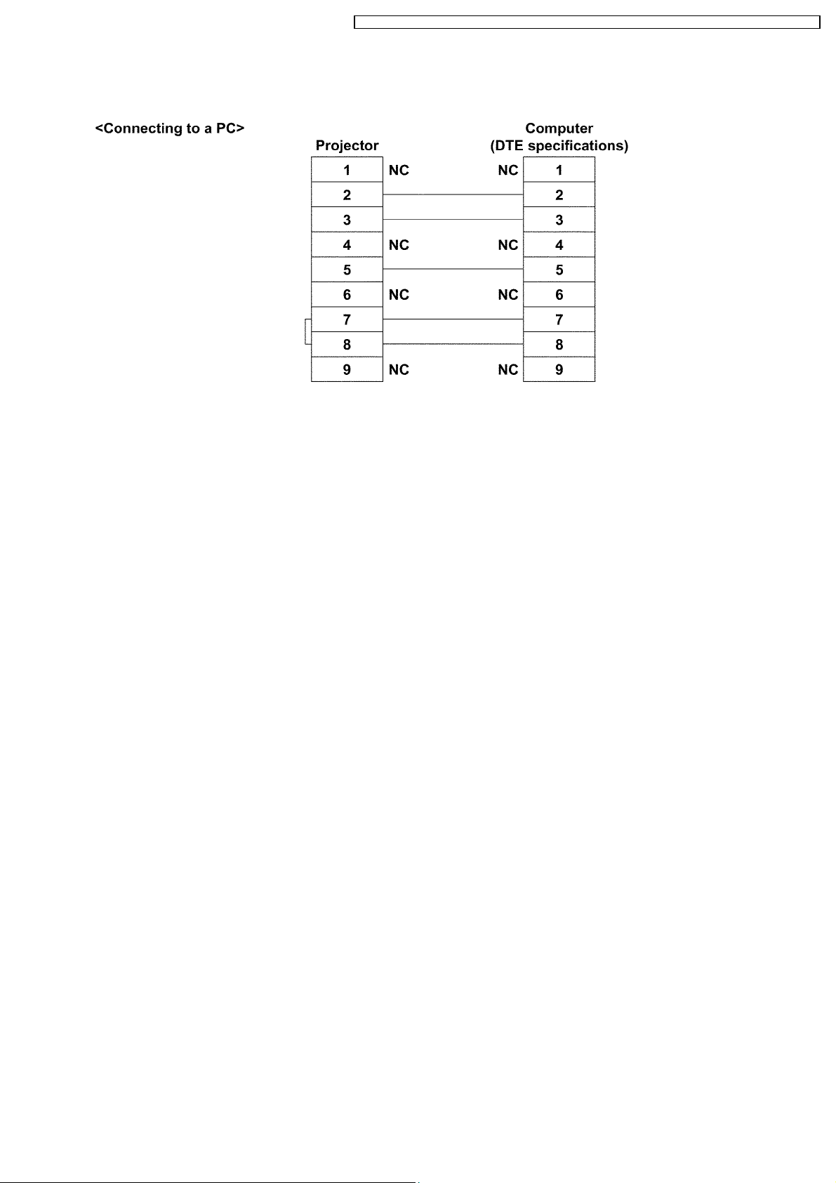
5.6. Cable specifications
Note
To connect the computer to the SERIAL terminal, prepare an adequate communication cable that fits to your personal
computer.
15
PT-D5700U / PT-D5700E / PT-D5700UL / PT-D5700EL / PT-DW5100U / PT-DW5100E / PT-DW5100UL / PT-DW5100EL
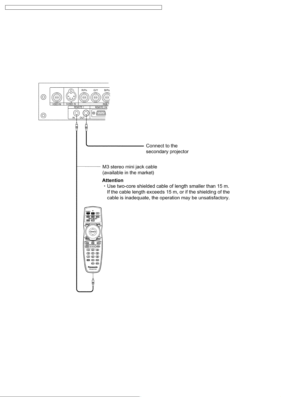
6 Using a Wired Remote Control
6.1. Connection Example
When multiple main units are connected in the system, connect the units with the M3 stereo mini jack cable available in the market
to simultaneously control the multiple main units with a single remote control unit through the REMOTE1 IN/OUT terminal. It is
effective to use the wired remote control in the environment in which an obstacle stands in the light path or where devices are
susceptible to outside light.
6.2. Setting the Projector ID Number for Remote Control
Every projector has its ID number and the ID number of the controlling projector must be set to the remote control in advance so
that the user can operate the remote control. The ID number of the projector is set to “ALL” on shipping, and use the ID ALL button
of the remote control when using only a single projector.
Procedure of ID setting
Press the ID SET button, and within five seconds use the number (0 to 9) buttons to enter the 2-digit ID number set by the
projector.
However, if the ID ALL button is pressed, the projector can be controlled regardless of the ID number of the projector
(simultaneous control mode).
16

PT-D5700U / PT-D5700E / PT-D5700UL / PT-D5700EL / PT-DW5100U / PT-DW5100E / PT-DW5100UL / PT-DW5100EL
Note:
· Do not press the ID SET button accidentally or carelessly because the ID number on the remote control can be set even
when no projector is around.
If the ID SET button is pressed, the ID number goes back to the one set before pressing the ID SET button unless a
numeric button is pressed within five seconds after the ID SET button is pressed.
· Your specified ID number is stored in the remote control unit unless another one is specified later. However, the stored
ID will be erased if the batteries of the remote control are left exhausted. When the dry cells are replaced, set the same
ID number again.
17
PT-D5700U / PT-D5700E / PT-D5700UL / PT-D5700EL / PT-DW5100U / PT-DW5100E / PT-DW5100UL / PT-DW5100EL
7 Support for Service
7.1. Supporting Methods
We will support according to the following methods.
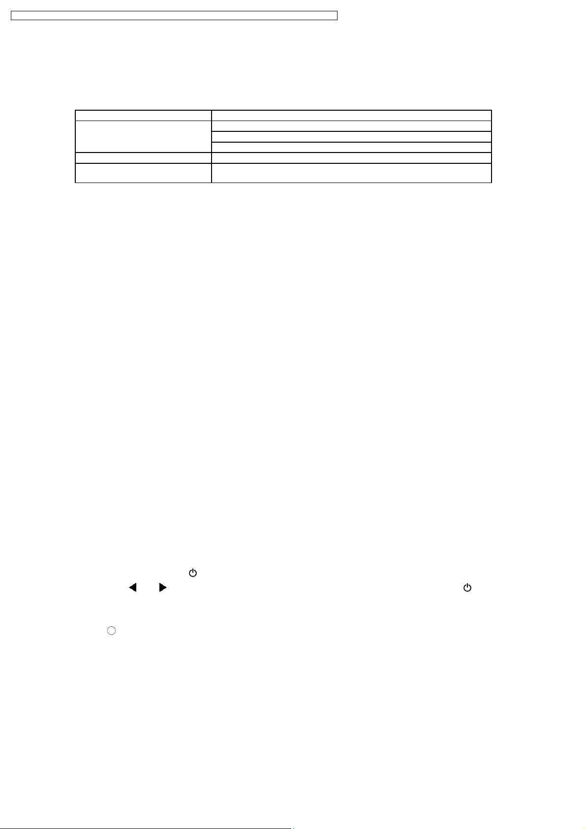
Supporting methods Applied parts
Replaced by module or block FM-Module (For specified components, supplies them discretely.)
Ballast module
Power module
Replaced by discrete components Other components
Replaced at the manufacturing
department
7.2. Note for Replacement of P.C.Boards
7.2.1. When replacing the A-P.C.Board
· Transfer the data of the original A-P.C.Board to the new A-P.C.Board using the adjustment software and a personal computer.
· If you cannot transfer the data that uses the adjustment software, remove IC2508 and IC2509 from the original board and
mount them on the new board.
* Consult your dealer or Authorized Service Center for the adjustment software.
Optical block unit (including DMD™ block), DMD™ drive module, Assembly
parts
7.3. Replacement of the lithium battery on the A-P.C.Board
If the lithium battery will be empty, replace it with a new one (CR2032 or equivalent).
Cautions
· Explosion may occur if replacing the battery with an incorrect one.
· Dispose of used batteries according to the instructions.
8 Cautions for Service
Service or repair the product according to service information on the service manual, etc. so that a fire, injury or electric shock
caused by an improper repair may not occur.
1. Do not modify equipments, components and materials when attempting to service or repair.
2. Do not repair nor connect wires even in case of a part of the disconnection when the wiring unit is supplied as a replacement
parts, replace the wiring unit (complete).
3. For a fasten terminal (push-in type terminal), pull out or insert straightly without twisting it.
8.1. Servicing Methods
· Never unplug the power cord from the outlet, open the circuit breaker, or perform other procedures to cut off the power line
during the operation of any cooling fan.
· Be sure to unplug the power cord from the power outlet before servicing.
Powering off the projector
1. Press the POWER STANDBY "
2. Select "OK" with
The projection of the image stops, and power indicator of the main unit lights up orange. (The cooling fan keeps running.)
3. Wait until the power indicator of the main unit turns to red (i.e., until the cooling fan stops).
4. Press the "
or button and press the ENTER button. (or press the POWER STANDBY " " button again.)
" marked side of the MAIN POWER switch to remove all power from the projector.
" button.
8.2. Light Source Lamp
Strong light is emitted from the projector´s lens. Never look into the lens while the projector is being used. If you look directly into
this light, it can hurt and damage your eyes.
18
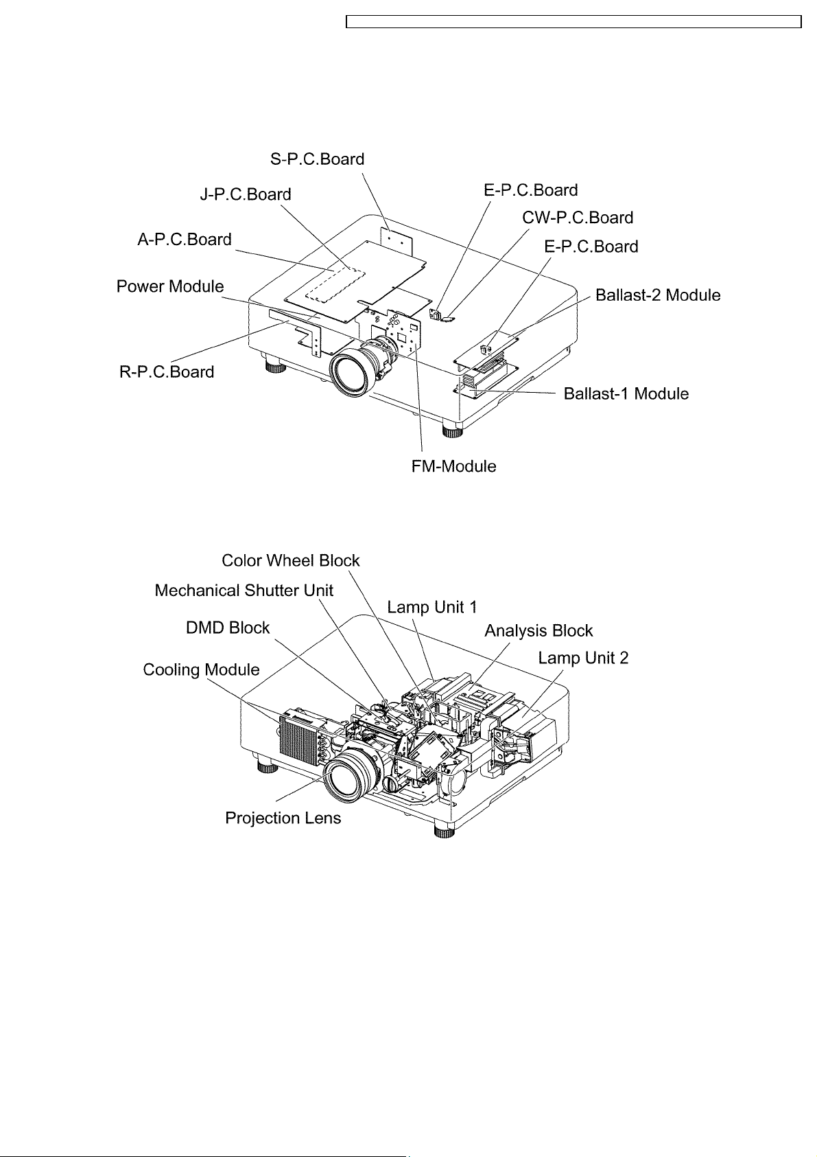
9 Parts Location
9.1. Electrical Parts Location
PT-D5700U / PT-D5700E / PT-D5700UL / PT-D5700EL / PT-DW5100U / PT-DW5100E / PT-DW5100UL / PT-DW5100EL
9.2. Electromechanical Parts Location
19
PT-D5700U / PT-D5700E / PT-D5700UL / PT-D5700EL / PT-DW5100U / PT-DW5100E / PT-DW5100UL / PT-DW5100EL
10 Replacement of Lamp Unit
10.1. Before replacing the Lamp Unit
WARNING!
· When replacing the lamp, allow it to cool for at least one hour before handling it.
· Make sure that two lamp units are always installed.
10.1.1. Precautions on lamp unit replacement
Remove the power plug and confirm that the surroundings of the lamp unit have cooled off.
· Be careful when handling a light source lamp. The lamp unit has high internal pressure. If improperly handled, explosion might
result.
· A used lamp unit may burst if it is handled violently.
For disposition of used lamps, request an industrial waste disposal contractor.
· If you continue to use a lamp after the replacement time, the lamp may break.
· Philips screwdriver is necessary when replacing a lamp unit.
Take care not to slip your hand when using a screwdriver.
· It is not possible to turn on the power unless two lamp units are installed.
· A lamp unit is an optional part. Contact the dealer.
Replacement lamp unit model No.: ET-LAD57 (single bulb), ET-LAD57W (double bulbs)
· Other lamps than specified above cannot be used. Be sure to use the specified lamp.
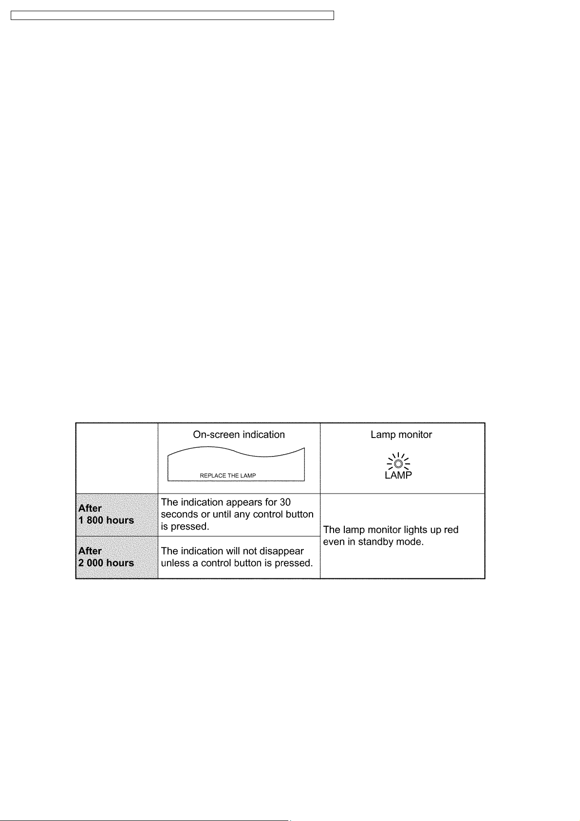
10.2. When to replace the Lamp Unit
The lamp units are consumable parts. The lamp brightness decreases gradually as the cumulative operating time increases, so
periodic replacement is necessary. The replacement guideline is 2 000 hours, although the lamp may become dead (will not light)
before 2 000 hours is reached depending on the characteristics of individual lamps and other factors such as the operating
conditions and the installation environment. Therefore, it is recommended for the user to keep a spare lamp unit.
The risk of the lamp bursting increases after 2 000 hours of operation, so the lamp unit turns off automatically.
20
PT-D5700U / PT-D5700E / PT-D5700UL / PT-D5700EL / PT-DW5100U / PT-DW5100E / PT-DW5100UL / PT-DW5100EL
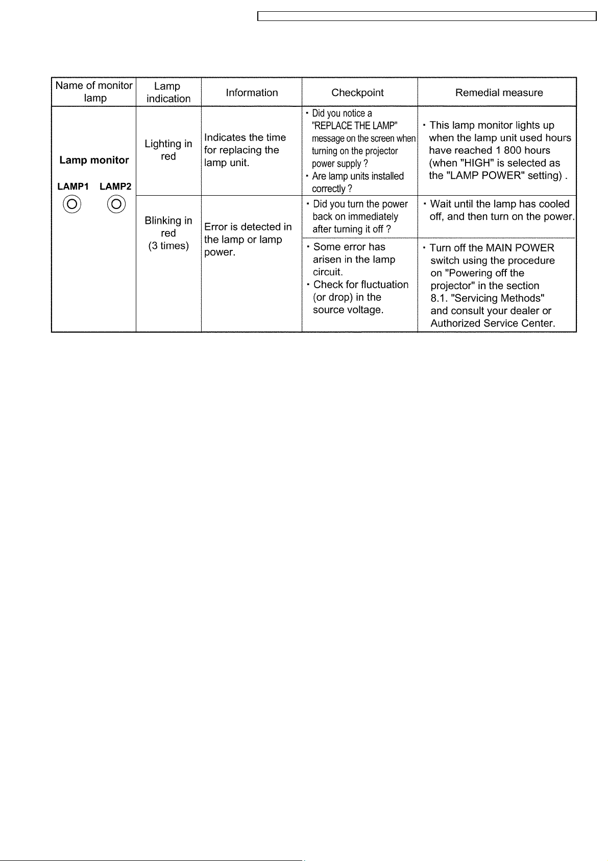
10.3. Indication of Lamp Monitor
21
PT-D5700U / PT-D5700E / PT-D5700UL / PT-D5700EL / PT-DW5100U / PT-DW5100E / PT-DW5100UL / PT-DW5100EL
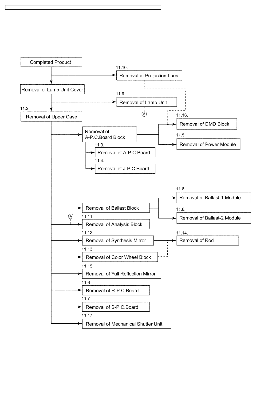
11 Disassembly Instructions
11.1. Flowchart for Disassembly
To assemble, reverse the disassembly procedures.
22
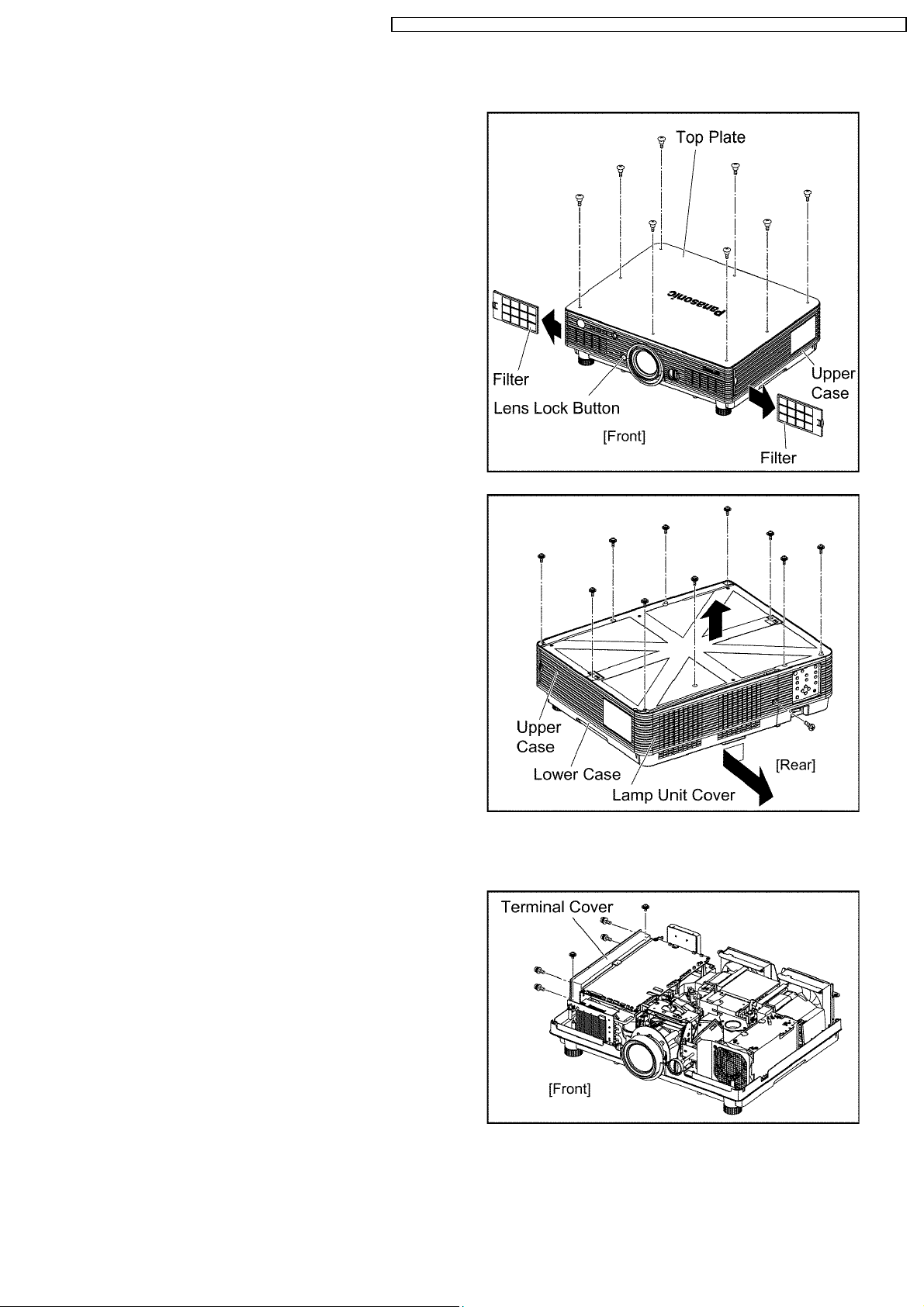
11.2. Removal of Upper Case
(1) Unscrew the 8 screws and remove the top plate.
(2) Remove the filters (R, L). (Pull them horizontally out.)
PT-D5700U / PT-D5700E / PT-D5700UL / PT-D5700EL / PT-DW5100U / PT-DW5100E / PT-DW5100UL / PT-DW5100EL
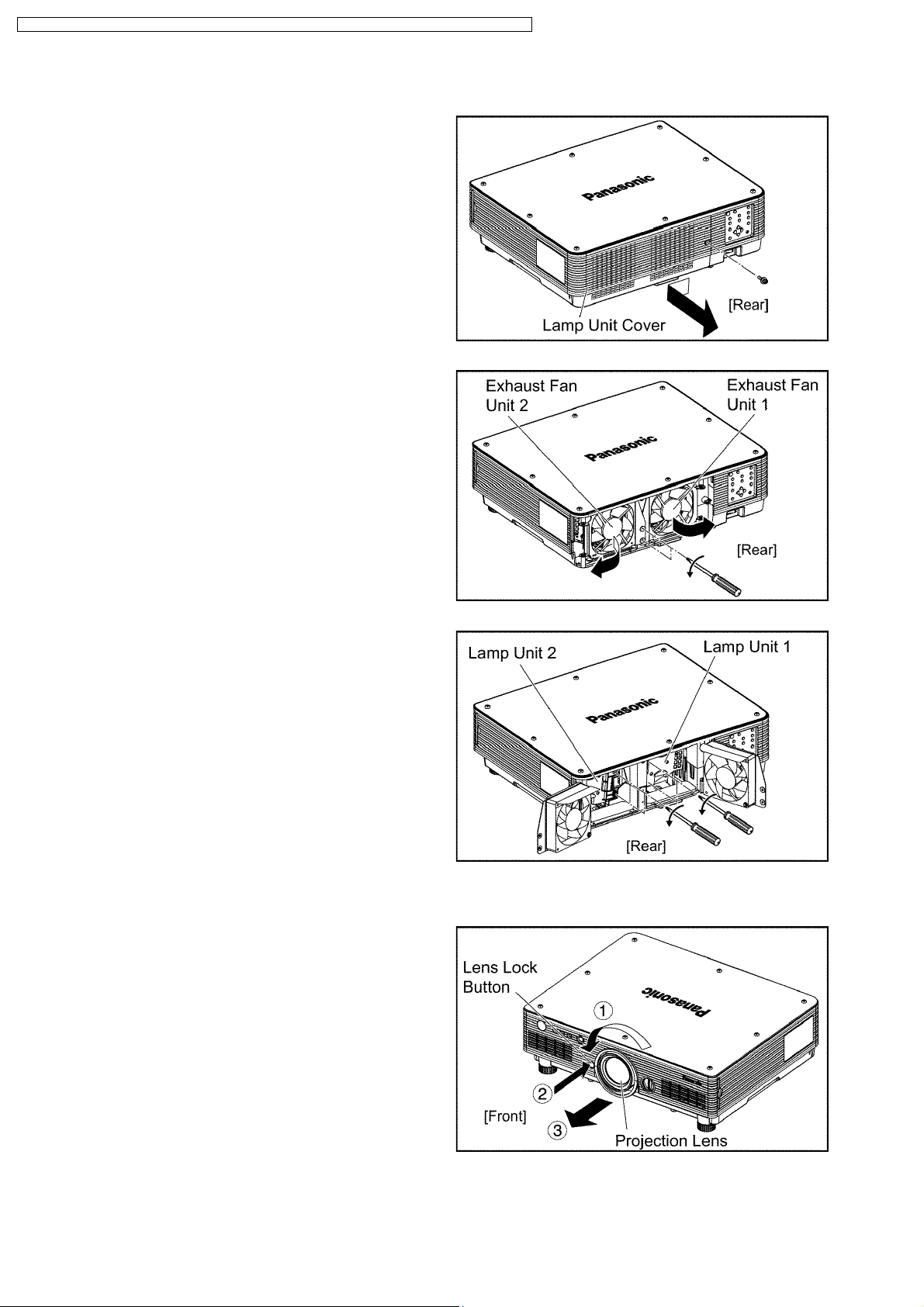
(3) Unscrew the 1 screw and remove the lamp unit cover while
sliding it horizontally.
(4) Unscrew the 10 screws and remove the upper case.
Note:
· Confirm the lens lock button actuates correctly when
you reassemble the upper case as it was.
· When you attach the upper case, take care not caught
nor protruding of the dustproof sheet around the
projection lens.
· After attaching the upper case, remove and reinstall the
projection lens according to the section 11.10.
"Removal of Projection Lens" because the dustproof
sheet might protrude or deform.
11.3. Removal of A-P.C.Board
(1) Remove the upper case according to the section 11.2. "Removal
of Upper Case".
(2) Unscrew the 6 screws and remove the terminal cover.
23
PT-D5700U / PT-D5700E / PT-D5700UL / PT-D5700EL / PT-DW5100U / PT-DW5100E / PT-DW5100UL / PT-DW5100EL
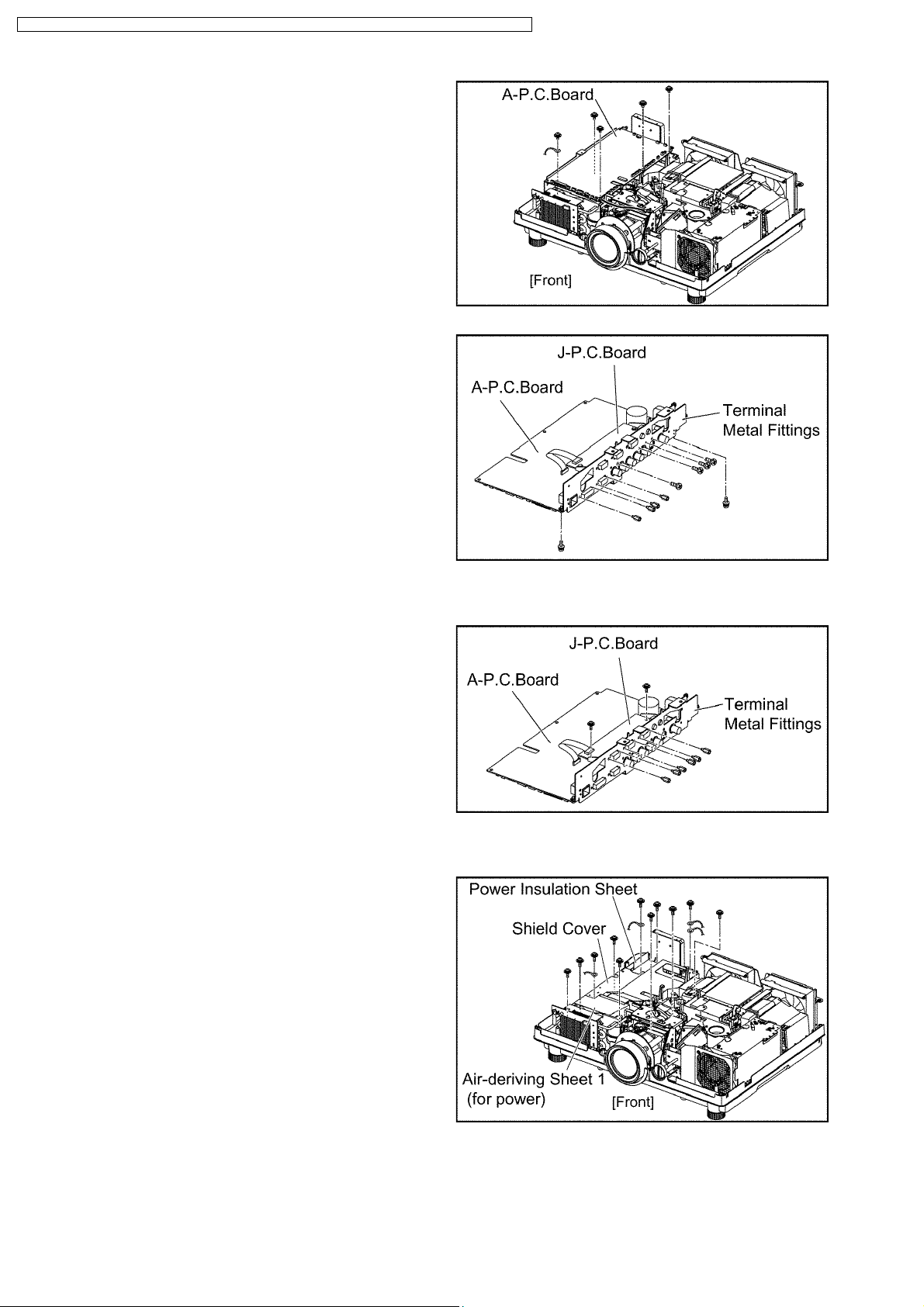
(3) Unscrew the 5 screws and remove the A-P.C.Board blo ck.
(4) Pull out the flexible cable connected to the J-P.C.Board. (The
reverse side of A-P.C.Board)
(5) Unscrew the 10 screws and remove the A-P.C.Board. (The block
of the terminal metal fittings and J-P.C.Board remains.)
11.4. Removal of J-P.C.Board
(1) Remove the A-P.C.Board block according to the steps 1 through
3 in the section 11.3. "Removal of A-P.C.Board".
(2) Pull out the flexible cable connected to the A-P.C.Board.
(3) Unscrew the 8 screws and remove the J-P.C.Board.
11.5. Removal of Power Module
(1) Remove the A-P.C.Board block according to the steps 1 through
3 in the section 11.3. "Removal of A-P.C.Board".
(2) Unscrew the 1 screw and remove the power insulation sheet.
(3) Unscrew the 3 screws and release the 3 grounding terminals.
(4) Unscrew the 5 screws and remove the shield cover.
(5) Unscrew the 2 screws and remove the air-deriving sheet 1 (for
power).
24
PT-D5700U / PT-D5700E / PT-D5700UL / PT-D5700EL / PT-DW5100U / PT-DW5100E / PT-DW5100UL / PT-DW5100EL
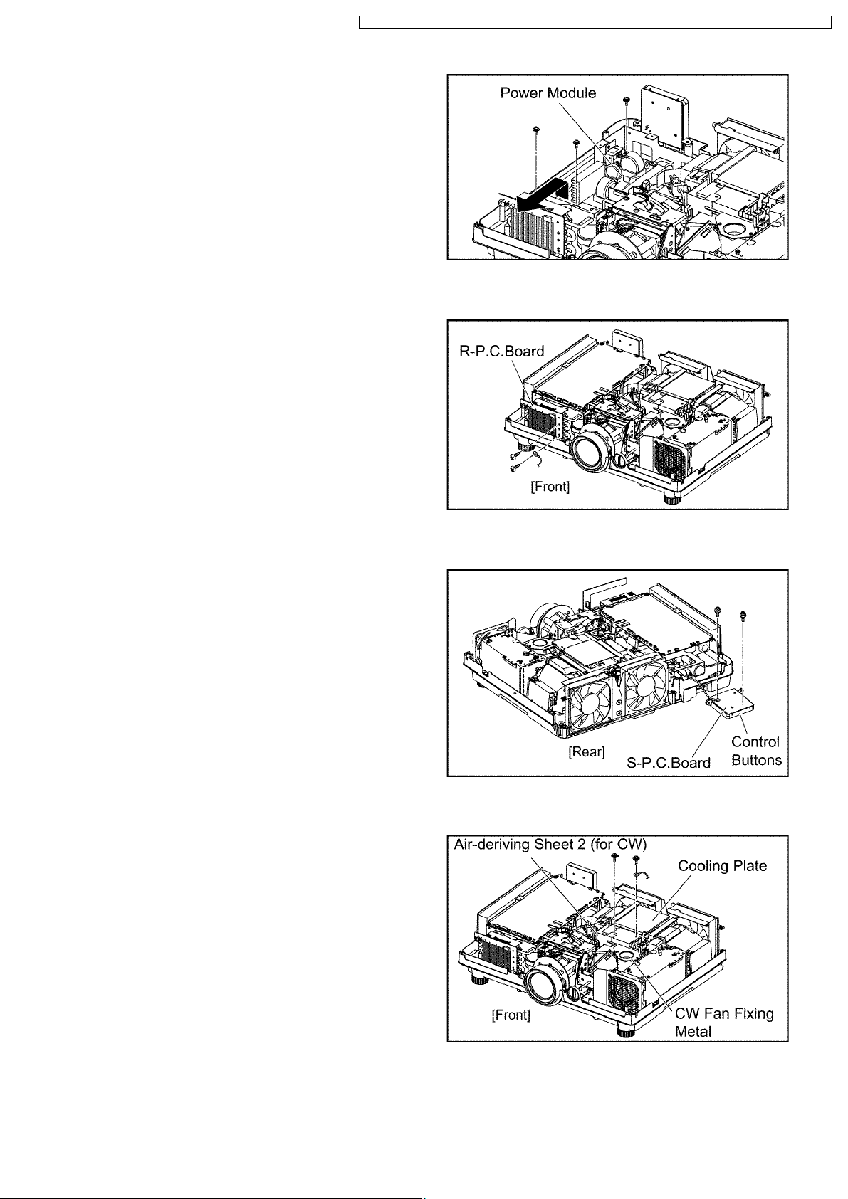
(6) Unscrew the 3 screws and remove the power module.
11.6. Removal of R-P.C.Board
(1) Remove the upper case according to the section 11.2. "Removal
of Upper Case".
(2) Unscrew the 2 screws and remove the R-P.C.Board.
11.7. Removal of S-P.C.Board
(1) Remove the upper case according to the section 11.2. "Removal
of Upper Case".
(2) Unscrew the 2 screws and remove the S-P.C.Board from the
control buttons.
11.8. Removal of Ballast-1 and Ballast-2 Modules
(1) Remove the upper case according to the section 11.2. "Removal
of Upper Case".
(2) Unscrew the 2 screws and remove the air-deriving sheet 2 (for
CW), the CW fan fixing metal and the Cooling plate.
25
PT-D5700U / PT-D5700E / PT-D5700UL / PT-D5700EL / PT-DW5100U / PT-DW5100E / PT-DW5100UL / PT-DW5100EL
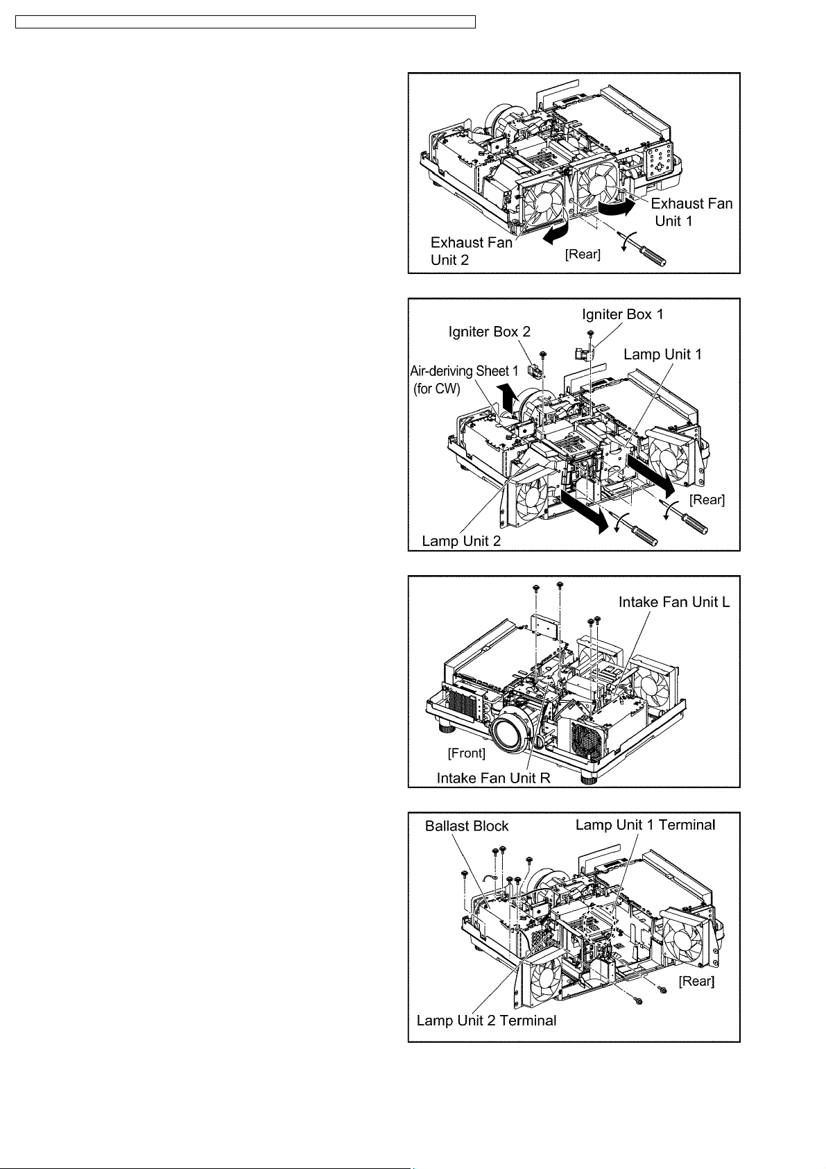
(3) Loosen the 2 screws until they idle and open the exhaust fan unit
1 and 2.
(4) Loosen each of 2 screws fixing the lamp units until they idle,
remove the lamp units 1 and 2.
(5) Unscrew each of 1 screw and release the 2 igniter boxes.
(6) Remove the air-deriving sheet 1 (for CW).
(7) Unscrew the 2 screws and remove the intake fan unit L.
(8) Unscrew the 2 screws and remove the intake fan unit R.
(9) Unscrew the 1 screw and release the lamp unit 1 terminal.
(10) Unscrew the 1 screw and release the lamp unit 2 terminals.
(11) Unscrew the 3 screws and release the grounding terminals.
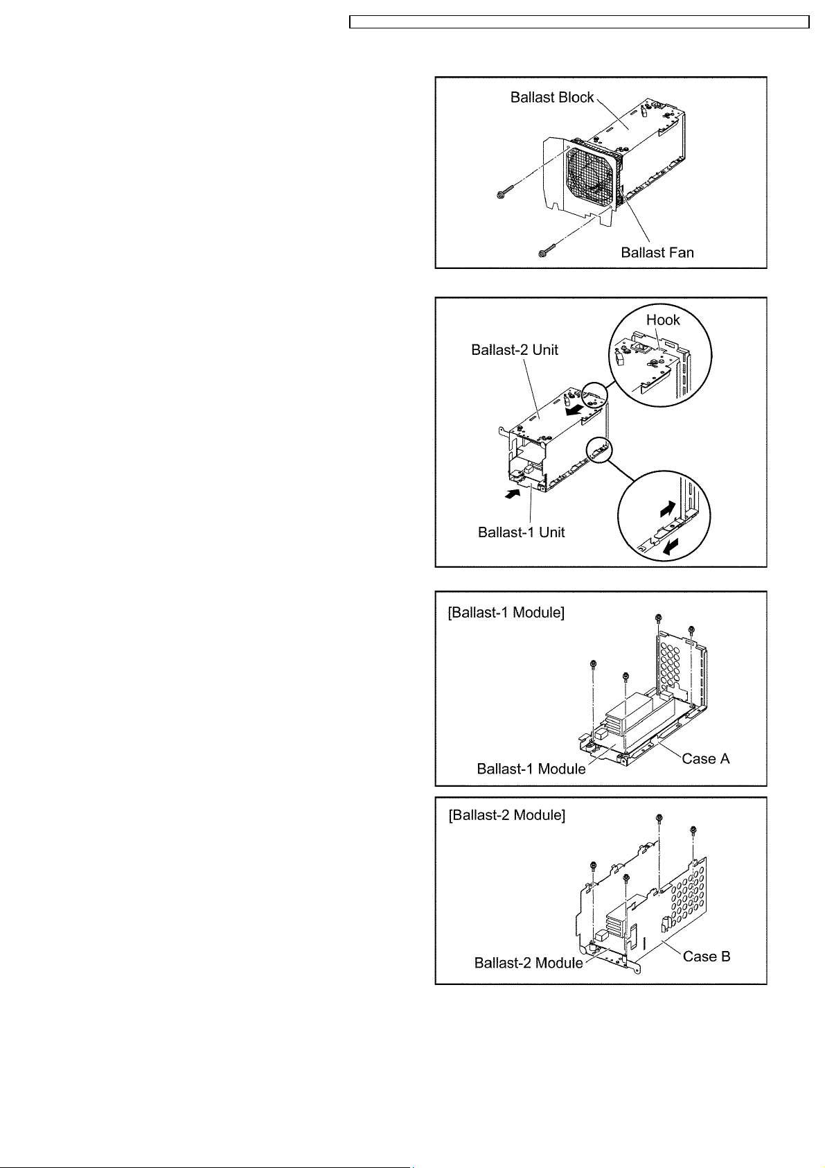
(12) Unscrew the 3 screws and release the ballast block.
26
PT-D5700U / PT-D5700E / PT-D5700UL / PT-D5700EL / PT-DW5100U / PT-DW5100E / PT-DW5100UL / PT-DW5100EL
(13) Unscrew the 2 screws and remove the ballast fan.
(14) Disconnect the connectors to the ballast-1 and ballast-2 units.
(15) While sliding the ballast-1 and ballast-2 units mutually,
disconnect their hooks and separate the units.
Note:
· Work carefully not to deform the ballast unit case (A,
B).
(16) Unscrew the 4 screws and remove the ballast module.
27
PT-D5700U / PT-D5700E / PT-D5700UL / PT-D5700EL / PT-DW5100U / PT-DW5100E / PT-DW5100UL / PT-DW5100EL
11.9. Removal of Lamp Unit
(1) Unscrew the 1 screw fixing the lamp unit cover and slightly slide
the cover horizontally and remove it.
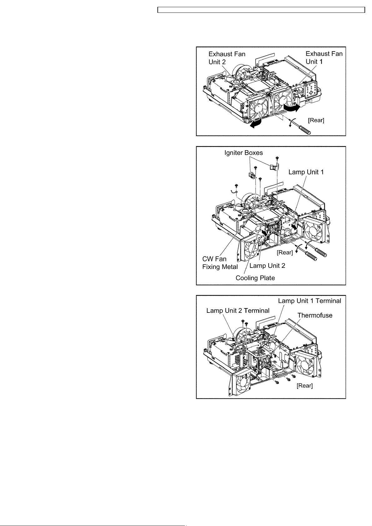
(2) Loosen the 2 screws until they idle and open the exhaust fan
units outside.
(3) Loosen each of 2 screws fixing the lamp unit until they idle, hold
the grip and take the lamp unit out.
11.10. Removal of Projection Lens
(1) Fully turn the projection Lens countercloc kwise.
(2) Turn the projection lens counterclockwise in addition while
pressing the lens lock button.
(3) Remove the projection lens.
28
PT-D5700U / PT-D5700E / PT-D5700UL / PT-D5700EL / PT-DW5100U / PT-DW5100E / PT-DW5100UL / PT-DW5100EL
11.11. Removal of Analy sis Block
(1) Remove the upper case according to the section 11.2. "Removal
of Upper Case".
(2) Loosen the 2 screws until they idle and open the exhaust fan
units 1 and 2 outside.
(3) Loosen each of 2 screws fixing the lamp units until they idle,
remove the lamp units 1 and 2.
(4) Unscrew the 2 screws and remove the CW fan fixing metal with
fan and the cooling plate.
(5) Unscrew each of 1 screw and release the 2 igniter boxes.
(6) Unscrew the 1 screw for the lamp unit 1 terminal.
(7) Unscrew the 1 screw for the lamp unit 2 terminal.
(8) Unscrew the 1 screw and remove the thermofuse.
29
PT-D5700U / PT-D5700E / PT-D5700UL / PT-D5700EL / PT-DW5100U / PT-DW5100E / PT-DW5100UL / PT-DW5100EL
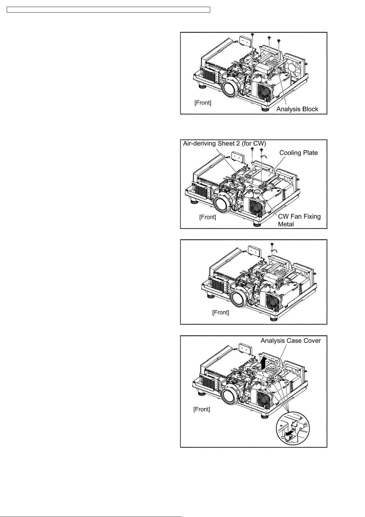
(9) Unscrew the 3 screws and remove the analysis block.
11.12. Removal of Synthesis Mirror
(1) Remove the upper case according to the section 11.2. "Removal
of Upper Case".
(2) Unscrew the 2 screws and remove the CW fan fixing metal with
fan and the cooling plate.
(3) Unscrew the 1 screw and remove the grounding terminal.
(4) Unhook the 4 hooks and remove the analysis case cover.
Notes:
· Work carefully not to deform the hooks of the analysis
case cover.
· When the analysis case cover is removed, be careful
not to touch the rod.
30
 Loading...