

Panasonic PT-D5700E, PT-DW5100E, PT-DW5100EL, PT-D5700EL User Manual
DLPTMBased Projector Commercial Use
Operating Instructions
Read these instructions completely before operating this unit.
TQBJ0220-1
Model No. PT-D5700E
PT-D5700EL
PT-DW5100E
PT-DW5100EL
ENGLISHDEUTSCHFRANÇAISESPAÑOLITALIANO

2
Dear Panasonic Customer:
This instruction booklet provides all the necessary operating information that you might require. We hope it will help
you to get the most performance out of your new product, and that you will be pleased with your Panasonic DLP
TM
based projector.
The serial number of your product may be found on its back. You should note it in the space provided below and
retain this booklet in case service is required.
Model number: PT-D5700E/PT-D5700EL/PT-DW5100E/PT-DW5100EL
Serial number:
IMPORTANT SAFETY NOTICE
WARNING: THIS APPARATUS MUST BE EARTHED.
WARNING: To prevent damage which may result in fire or shock hazard, do not expose
this appliance to rain or moisture.
Machine Noise Information Ordinance 3. GSGV, January 18 1991: The sound pressure level
at the operator position is equal or less than 70 dB (A) according to ISO 7779.
WARNING:
1) Remove the plug from the wall outlet when this unit is not in use for a prolonged period of time.
2) To prevent electric shock, do not remove cover. No user serviceable parts inside. Refer servicing to qualified
service personnel.
3) Do not remove the earthing pin on the power plug. This apparatus is equipped with a three prong earthingtype power plug. This plug will only fit an earthing-type power outlet. This is a safety feature. If you are unable
to insert the plug into the outlet, contact an electrician. Do not defeat the purpose of the earthing plug.
CAUTION:
To assure continued compliance, follow the attached installation instructions, which include using the shielded
interface cables when connecting to a computer or peripheral device.
Pursuant to at the directive 2004/108/EC, article 9(2)
Panasonic Testing Centre
Panasonic Service Europe, a division of
Panasonic Marketing Europe GmbH
Winsbergring 15, 22525 Hamburg, F.R. Germany
3
ENGLISH
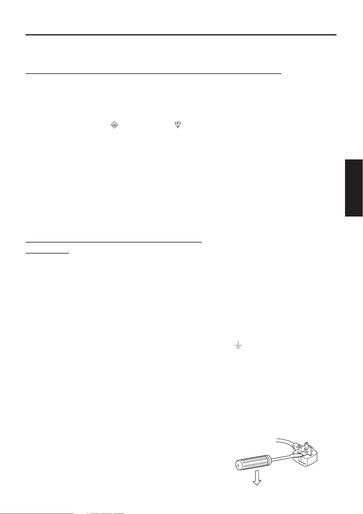
IMPORTANT: THE MOULDED PLUG (U.K. only)
FOR YOUR SAFETY
, PLEASE READ THE FOLLOWING TEXT CAREFULL
Y
.
This appliance is supplied with a moulded three pin mains plug for your safety and convenience.
A 13 amp fuse is fitted in this plug. Should the fuse need to be replaced, please ensure that the
replacement fuse has a rating of 13 amps and that it is approved by ASTA or BSl to BS1362.
Check for the ASTA mark or the BSl mark on the body of the fuse.
If the plug contains a removable fuse cover, you must ensure that it is refitted when the fuse is
replaced. If you lose the fuse cover, the plug must not be used until a replacement cover is
obtained. A replacement fuse cover can be purchased from an Authorized Service Centre.
If the fitted moulded plug is unsuitable for the socket outlet in your home, then the fuse
should be removed and the plug cut off and disposed of safely. There is a danger of
severe electrical shock if the cut off plug is inserted into any 13 amp socket.
If a new plug is to be fitted, please observe the wiring code as shown below.
If in any doubt, please consult a qualified electrician.
WARNING: –THIS APPLIANCE MUST BE EARTHED.
IMPORTANT: –The wires in this mains lead are coloured in accordance with the following code: –
Green-and-Yellow: Earth
Blue: Neutral
Brown: Live
As the colours of the wire in the mains lead of this appliance may not correspond with the
coloured markings identifying the terminals in your plug, proceed as follows.
The wire which is coloured GREEN-AND-YELLOW must be connected to the terminal in the
plug which is marked with the letter E or by the Earth symbol or coloured GREEN or
GREEN-AND-YELLOW.
The wire which is coloured BLUE must be connected to the terminal in the plug which is
marked with the letter N or coloured BLACK.
The wire which is coloured BROWN must be connected to the terminal in the plug which is
marked with the letter L or coloured RED.
How to replace the fuse. Open the fuse compartment with
a screwdriver and replace the fuse.
FUSE

4
Contents
IMPORTANT SAFETY NOTICE ..................................2
Precautions with regard to safety ............................5
Accessories ................................................................7
Precautions on handling ...........................................8
Name and function of parts.......................................9
Remote control ..................................................................9
Front and side of the projector ........................................11
Rear view of the main unit/Controls on rear panel ..........12
Side-mounted connection terminals ................................13
Using the remote control unit .................................14
Loading dry cells .............................................................14
Effective range of remote control operation ....................14
Setting projector ID number to remote control ................15
Connect to the projector to use with a cable ...................15
Installation ................................................................16
Projection schemes .........................................................16
Installation geometry .......................................................16
Projection distance by projection lens .............................17
Calculation formulas for projection distance by lens types
..19
Connection ...............................................................20
Setup precautions ...........................................................20
Example of connecting with AV products ........................21
Example of connecting with PCs.....................................21
Projection..................................................................22
Powering up the projector ...............................................22
Making adjustment and selection ....................................22
Powering off the projector ...............................................23
Direct power off function..................................................23
How to install and remove the projection lens......24
How to install the projection lens.....................................24
How to remove the projection lens ..................................24
How to adjust the lens .............................................24
How to adjust the FOCUS, ZOOM and SHIFT................24
How to adjust the lens position to the left or right............25
Status function .........................................................25
Automatic adjustment (AUTO SETUP)...................25
Using the SHUTTER function..................................25
On-screen menus.....................................................26
Structure of menu screens ..............................................26
Basic menu operations....................................................27
Returning to the previous page .......................................27
Menu items shown in black characters ...........................27
Menu items setting ..........................................................27
Resetting to the factory default........................................27
Adjusting the picture ...............................................28
PICTURE MODE.............................................................28
CONTRAST.....................................................................28
BRIGHTNESS .................................................................28
COLOR............................................................................28
TINT ................................................................................28
COLOR TEMP.................................................................28
WHITE GAIN ...................................................................28
SYSTEM DAYLIGHT VIEW ............................................28
SHARPNESS ..................................................................29
NOISE REDUCTION.......................................................29
AI .....................................................................................29
SYSTEM SELECTOR .....................................................29
Adjusting the position .............................................29
SHIFT ..............................................................................29
ASPECT ..........................................................................29
ZOOM..............................................................................30
CLOCK PHASE...............................................................30
KEYSTONE.....................................................................30
How to use ADVANCED MENU ...............................30
DIGITAL CINEMA REALITY ...........................................30
BLANKING ......................................................................30
INPUT RESOLUTION .....................................................31
CLAMP POSITION..........................................................31
EDGE BLENDING...........................................................31
RASTER POSITION........................................................32
XGA MODE .....................................................................32
SXGA MODE...................................................................32
Changing the display language ..............................32
OPTION1 settings.....................................................33
COLOR MATCHING .......................................................33
Adjusting the colour matching using a colourimeter........33
COLOR CORRECTION ..................................................34
CONTRAST MODE.........................................................34
AUTO SIGNAL ................................................................34
BACK COLOR.................................................................34
STARTUP LOGO ............................................................34
SUB MEMORY LIST .......................................................34
DVI EDID.........................................................................35
DVI SIGNAL LEVEL ........................................................35
FUNC1 ............................................................................35
OSD POSITION ..............................................................35
OSD MEMORY ...............................................................35
OPTION2 settings.....................................................36
PROJECTOR ID..............................................................36
INSTALLATION...............................................................36
ALTITUDE .......................................................................36
DIRECTION.....................................................................36
LAMP SELECT................................................................37
LAMP RELAY..................................................................37
LAMP POWER ................................................................37
RS-232C..........................................................................37
SYSTEM INFORMATION ...............................................38
AUTO POWER OFF........................................................38
DATE AND TIME.............................................................38
PASSWORD ...................................................................38
Displaying the internal test pattern ........................38
Cycle of displayed internal test patterns..........................38
Setting the network..................................................39
Returning the network function setting back to the factory setting
..39
Connecting the PC ...................................................39
System requirements ......................................................39
Connection example........................................................39
Using Web Browser Control ...................................40
Accessing from Web browser..........................................40
Password change page...................................................40
Basic control page...........................................................41
Detail control page ..........................................................42
Monitor information page.................................................42
Error information page.....................................................43
E-mail set up page ..........................................................44
Authentication server set up page...................................45
DNS server set up page ..................................................46
Ping test page .................................................................46
Contents of mail sent.......................................................47
Adjust clock page ............................................................47
Network config page........................................................48
Network status page........................................................48
Using the PJLinkTMprotocol ....................................49
Supported commands .....................................................49
PJLink
TM
security authentication ......................................49
Setting the security..................................................50
PASSWORD ...................................................................50
PASSWORD CHANGE ...................................................50
DISPLAY SETTING.........................................................50
TEXT CHANGE...............................................................50
CONTROL DEVICE SETUP ...........................................50
Using the serial terminals .......................................51
Examples of connection .................................................51
Pin assignments and signal names.................................51
Communication conditions ..............................................51
Basic format ....................................................................51
Control commands ..........................................................52
Cable specifications ........................................................52
Using the Remote 2 terminal...................................52
Indication of lamp monitor ......................................53
Cleaning and replacement of air filter....................54
Procedure of cleaning .....................................................54
Replacing the lamp unit...........................................55
When to replace the Lamp unit .......................................55
Lamp unit replacement steps ..........................................56
Ceiling Mount Bracket Safeguards.........................57
Before asking for service ........................................58
Specifications...........................................................59
Compatible Signal List ............................................61
Dimensions...............................................................62
Installation dimensions diagram ............................62

5
Precautions with regard to safety
ENGLISH
WARNING
If you notice smoke, strange smells or noise coming from the projector, disconnect the
power cord plug from the wall outlet.
• Do not continue to use the projector in such cases, otherwise fire or electric shocks could result.
• Check that no more smoke is coming out, and then contact an Authorized Service Centre for repairs.
• Do not attempt to repair the projector yourself, as this can be dangerous.
Installation work (such as ceiling suspension) should only be carried out by a qualified
technician.
• If installation is not carried out correctly, there is the danger that injury or electric shocks may occur.
• Use the dedicated ceiling mount bracket specified for the model.
• Use the provided safety wire cable and take measures to prevent the projector from falling.
Do not overload the wall outlet.
• If the power supply is overloaded (for example, by using too many adapters), overheating may occur and fire
may result.
Do not look into the lens while the projector is being used.
• Strong light is emitted from the projector’s lens. If you look directly into this light, it can hurt and damage your
eyes.
• Be especially careful not to let young children look into the lens. In addition, turn off the power and disconnect
the power cord plug when you are away from the projector.
Never attempt to modify or disassemble the projector.
• High voltages can cause fire or electric shocks.
• For any inspection, adjustment and repair work, please contact an Authorized Service Centre.
Do not install this projector in a place which is not strong enough to take the full weight
of the projector or on top of a surface which is unstable.
• If the projector is installed in a place which is not strong enough or on top of a surface which is sloped or
unstable, it may fall down or tip over, and severe injury or damage could result.
If foreign objects or water get inside the projector, or if the projector is dropped or the
cabinet is broken, disconnect the power cord plug from the wall outlet.
• Continued use of the projector in this condition may result in fire or electric shocks.
• Contact an Authorized Service Centre for repairs.
Do not place liquid containers on top of the projector.
Do not place the projector into water or let it become wet.
• If water spills onto the projector or gets inside it, fire or electric shocks could result.
• If any water gets inside the projector, contact an Authorized Service Centre.
Do not insert any foreign objects into the projector.
• Do not insert any metal objects or flammable objects into the projector or drop them onto the projector, as doing
so can result in fire or electric shocks.
Use only the power cord supplied with the projector.
Do not use the supplied power cord with equipment other than the projector.
• Failure to observe this may result in electric shocks.
Insert the power cord plug securely into the wall outlet.
• If the plug is not inserted correctly, electric shocks or overheating could result.
• Do not use plugs which are damaged or wall outlets which are coming loose from the wall.
Do not do anything that might damage the power cord or the power cord plug.
• Do not damage the power cord, make any modifications to it, place it near any hot objects, bend it excessively,
twist it, pull it, place heavy objects on top of it or wrap it into a bundle.
• If the power cord is used while damaged, electric shocks, short-circuits or fire may result.
• Ask an Authorized Service Centre to carry out any repairs to the power cord that might be necessary.
Clean the power cord plug regularly to prevent it from becoming covered in dust.
• If dust builds up on the power cord plug, the resulting humidity can damage the insulation, which could result in
fire. Pull the power cord plug out from the wall outlet and wipe it with a dry cloth.
• If not using the projector for an extended period of time, pull the power cord plug out from the wall outlet.
Do not handle the power cord plug with wet hands.
• Failure to observe this may result in electric shocks.

6
Precautions with regard to safety
Do not set up the projector in humid or dusty places or in places where the projector may
come into contact with oily smoke or steam.
• Using the projector under such conditions may result in fire, electric shocks or plastic deterioration. The plastic
deterioration may cause the falling down of the projector which is mounted in the ceiling.
Do not place the projector on soft materials such as carpets or sponge mats.
• Doing so may cause the projector to overheat, which can cause burns, fire or damage to the projector.
During a thunderstorm, do not touch the projector or the cable.
• Electric shocks can result.
Do not place your hands or other objects close to the air outlet port.
• Heated air comes out of the air outlet port. Do not place your hands or face, or objects which cannot withstand
heat close to this port [allow at least 50 cm of space], otherwise burns or damage could result.
Do not use or handle the batteries improperly.
• Failure to observe these precautions may cause the batteries to leak, overheat, explode or catch fire.
- Do not disassemble the dry cell batteries.
- Do not heat, or disassemble the batteries or place them into fire or liquids such as water.
- Do not connect the + and - terminals with wire or other metallic objects.
- Do not store batteries together with metallic objects such as necklaces or hairpins.
- Make sure the polarities (+ and -) are correct when inserting the batteries.
- Do not use a new battery together with an old battery or mix different types of batteries.
- Do not use batteries with the outer covering peeling away or removed.
- Do not use rechargeable batteries in place of the dry cell batteries.
- The batteries have a protective outer covering. Do not remove this covering, as this may result in a short
circuit.
If the battery fluid leaks, do not touch it with bare hands, and take the following
measures if necessary.
• Battery fluid entering your eyes may result in loss of sight. In this case, do not rub your eyes. Rinse with clean
water and seek medical advice immediately.
• Battery fluid on your skin or clothing may result in skin inflammation or injury. Rinse with clean water and seek
medical advice immediately.
Remove empty batteries from the remote control at once.
• Do not leave empty batteries inside the equipment, as this may cause the batteries to leak, overheat or explode.
Before replacing the lamp, be sure to disconnect the power cord plug from the wall
outlet.
• Electric shocks or explosions can result if this is not done.
When replacing the lamp, allow it to cool for at least one hour before handling it.
• The lamp cover gets very hot, and touching it can cause burns.
Do not disassemble the lamp unit.
• If the lamp section breaks, it may cause injury.
When disconnecting the power cord, hold the plug, not the cord.
• If the power cord itself is pulled, the cord will become damaged, and fire, short-circuits or serious electric shocks
may result.
Always disconnect all cables before moving the projector.
• Moving the projector with cables still attached can damage the cables, which could cause fire or electric shocks
to occur.
Do not place a projector or other heavy object on top of the unit.
Do not put your weight on this projector.
• Failure to observe this may cause the projector to become unbalanced and fall, which could result in damage or
injury.
• The projector may be damaged or deformed.
Do not prevent heat loss.
• Doing so may cause the projector to overheat, which can cause fire or damage to the projector.
• Do not place the projector in narrow, badly ventilated places such as closets or bookshelves.
• Do not place the projector on cloth or papers, as these materials could be drawn into the air inlet port.
Caution
7
ENGLISH
Accessories
Check that all of the accessories shown below have been included with your projector.
If the lamp has broken, ventilate the room immediately. Do not touch or bring your face
close to the broken pieces.
• Failure to observe this may cause the user to absorb the gas which was released when the lamp broke and
which contains nearly the same amount of mercury as fluorescent lamps, and the broken pieces may cause
injury.
• If you believe that you have absorbed the gas or that the gas has got into your eyes or mouth, seek medical
advice immediately.
• Ask your dealer about the replacement of the lamp unit and check the inside of the projector.
If not using the projector for an extended period of time, disconnect the power cord plug
from the mains socket.
• If dust builds up on the power cord plug, the resulting humidity may damage the insulation, which could result in
fire.
Disconnect the power cord plug from the wall outlet as a safety precaution before
carrying out any cleaning.
• Electric shocks can result if this is not done.
Be careful not to catch your fingers between the lens and shroud when shifting the lens.
• Do not catch your fingers between the lens and shroud when shifting the lens as it may cause injury.
Ask an Authorized Service Centre to clean inside the projector at least once a year.
• If dust is left to build up inside the projector without being cleaned out, it can result in fire or problems with
operation.
• It is a good idea to clean the inside of the projector before the season for humid weather arrives. Ask your
nearest Authorized Service Centre to clean the projector when required. Please discuss with the Authorized
Service Centre regarding cleaning costs.
If not using the projector for an extended period of time, remove the batteries from the
remote control.
• Failure to do so may cause the batteries to leak, overheat, catch fire or explode, possibly resulting in fire or
corruption of surrounding areas.
Do not use the old lamp unit.
• The lamp section may break.
Do not place the projector in extremely hot locations.
• Doing so may cause the outer casing or internal components to deteriorate, or result in fire.
• Take particular care in locations exposed to direct sunlight or near stoves.
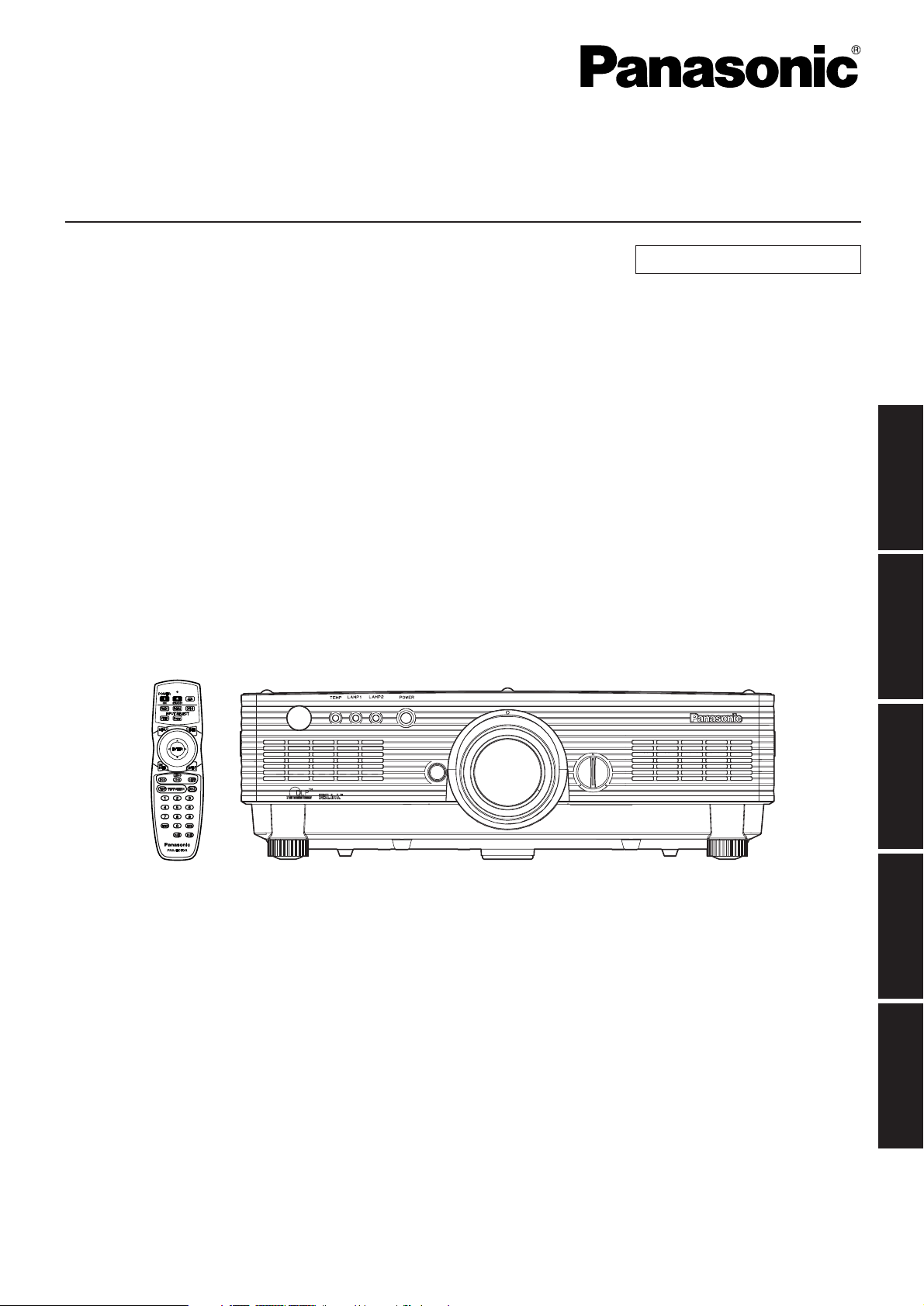
Remote control unit
[N2QAYB000164 x 1]
Battery for remote
control unit (AA)
[R6DW/2ST]
Lens cover
[TKKL5244-1 x 1]
Sefety cable
[TTRA0146]
Wire cable (x 1)
Wire fastening M6
(Length:10 mm)
screw (x 1)
Power cord
for U.K.
[K2CT3FZ00003 x 1]
for Continental
[K2CM3FZ00003 x 1]

8
Precautions on handling
Precautions on transport
Make absolutely sure that the lens cap is in place when
transporting the projector or carrying it around. Both the
projector and the projection lens are precision-made
and, as such, are susceptible to vibration and impacts.
When transporting the projector and lens or carrying
them around, place them in the boxes in which they
were housed at the time of purchase, and take care to
keep them away from vibration and impacts.
Precautions on installation
Be sure to observe the following precautions when
installing the product.
Avoid installing the product in a place
exposed to vibrations or impacts.
If the projector is installed in a place where vibrations
are transmitted from a source of driving power and
others or mounted in a car or a vessel, vibrations or
impacts may be transmitted to the product to
damage the internal parts, causing failure. Install the
product in a place free from vibrations and impacts.
Do not move the projector while it is
operating or subject it to vibration or impact.
The service life of its internal motors may be shortened.
Do not install the projector near highvoltage power lines or power sources.
The product may be exposed to interference if it
is installed in the vicinity of high-voltage electrical
power lines or power sources.
Do not place the projector on a vinyl
sheet or carpet.
If a vinyl sheet sucked up and blocks the air filter
intake port, the internal temperature of the
projector may increase, which triggers the
protection circuit, turning off the power.
Be sure to ask a specialized technician
when installing the product to a ceiling.
If the product is to be installed hanging from the ceiling,
purchase an optional hanging attachment (for high
ceiling: Model No. ET-PKD56H) (for low ceiling: Model
No. ET-PKD55S). Please call a specialized technician or
contact an Authorized Service Centre for installation.
Install the projector so that it will be
supported only by its bottom panel and
by none of its other parts or surfaces.
Do not place the projector over 2 700 m
above sea level. When using it over 1 400
m above sea level, set the “ALTITUDE”,
described on page 36, to “HIGH”.
Otherwise the life of the product may be shortened. When
using it over 2 700 m above sea level, consult your dealer.
Lens Focus
Do not adjust the lens focus in the initial period
(within approx. 30 minutes) after switching the
projector on. The high clarity projector lens is
thermally affected by the light from the light source,
making the focus unstable in the period just after
switching on. Please allow a warm-up time of at
least 30 minutes before adjusting the lens focus.
Failure to do so may cause heating focus drift.
Disposal
To discard the product, call the dealer or a specialized dealer.
Precautions on use
To view clear images:
• The audience cannot enjoy high-contrast and
clear images if outside light or the illumination
interferes the screen surface. Draw window
curtains or blinds, turn off the lightings near the
screen or take other proper measures.
• Depending on where the projector is used,
there are rare occasions when hot air from the
air exhaust vents or the warm air from air
conditioning can cause a shimmering effect on
the screen. For this reason, take care not to
shield the air exhaust vents and consider the
direction of the air flowing from air conditioning.
Do not touch the surface of the
projection lens with bare hand.
If fingerprints or stains are left on the projection
lens surface, they are magnified and projected
on the screen. Keep your hands away from the
lens. Cover the lens with the supplied lens cap
when the projector is not used.
Lamp
A mercury lamp with high internal pressure is used
for the light source of this product. A high-pressure
mercury lamp has the following characteristics:
•
It may burst with a loud sound or end its life cycle
by not illuminating because of given impacts,
flaws, or deterioration due to used hours.
•
The life cycle of a mercury lamp varies according
to the individual difference or conditions of use.
In particular, turning the power on and off frequently
and/or repeatedly will greatly affect the life cycle.
•
In rare cases, it may burst shortly after the first lighting.
• The possibility of burst increases when the
lamp is used beyond the replacement time.
• If the lamp bursts, gas inside the lamp is
released and smoke may appear.
•
Lamp deterioration accelerates when used
continuously for 24 hours or more. Lamp
deterioration due to continuous use can be
reduced by using the “LAMP RELAY” function.
Cleaning and maintenance
Be sure to remove the power cord plug from the
receptacle before cleaning.
Use soft and dry cloth to clean the cabinet.
If stains are hard to remove, use a cloth
dampened with a kitchen detergent solution
(neutral) and squeezed to wipe the cabinet and
finish with a dry cloth. If a chemical wipe is used,
follow its instructions.
Do not clean the lens surface with fuzzy
or dusty cloth.
If dust adheres to the lens, it will be magnified
and projected on the screen.
Use a soft and clean cloth to wipe off dust.
9
ENGLISH
Name and function of parts
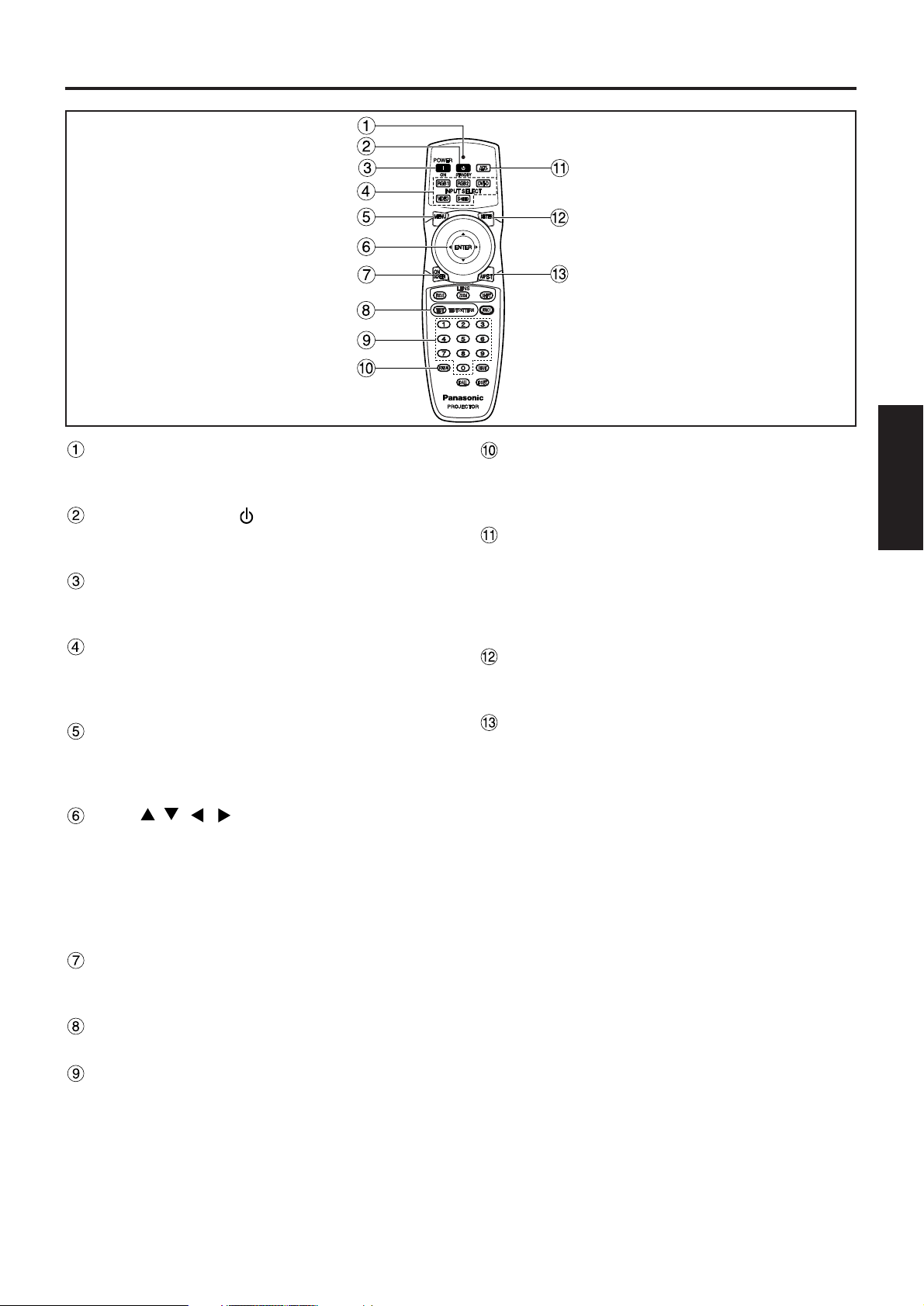
Remote control operation indicator lamp
The lamp flashes when any remote control button
is pressed.
POWER STANDBY ( ) button (page 23)
Switched the power to the “standby” mode if the
MAIN POWER has been put to the “l” position.
POWER ON ( I ) button (page 22)
Turns on the power if the MAIN POWER has been
put to the “l” position.
Input selector (RGB1, RGB2, DVI-D, VIDEO,
S-VIDEO) button
Use to toggle through the RGB1, RGB2, DVI-D,
VIDEO and S-VIDEO input ports.
MENU button (page 27)
Displays and clears the MAIN MENU. It can also
return to the previous screen when the menu is
displayed.
Arrow buttons (page 27)
Use these buttons to select an item on the menu
screen, change setting and adjust the level.
Also use them to enter the “SECURITY” password.
ENTER button (page 27)
Press this button to enter your menu selection or to
run function.
ON SCREEN button
This button turns on and off the on-screen
indication function.
TEST PATTERN button (page 38)
This displays the test pattern.
Numeric (0 - 9) buttons (pages 15, 38)
These buttons are used for systems where more
than one projector is being used.
They are used to enter ID numbers when selecting
an ID, and they are also used by service personnel
for entering passwords when password entry is
needed.
Remote control
STATUS button (page 25)
Press this button to display projector information. It
can also be used to send information about the
projector’s status via E-mail.
AUTO SETUP button (page 25)
Pressing this button while projecting an image
automatically corrects the picture positioning on
the screen. While the auto setup feature is active,
a message “AUTO SETUP” appears on the
screen.
SHUTTER button (page 25)
Press this button to black out the image
temporarily.
ASPECT button (page 29)
Switches the image aspect ratio.
10
Name and function of parts
Remote control transmitter window
Operate the remote control aiming at the remote
control receiver window on the main unit.
Remote control wired terminal (page 15)
To use the wired output terminal, connect the
remote control and the main unit with the M3
stereo mini jack cable available in the market.
LENS (FOCUS, ZOOM, SHIFT) buttons
(page 24)
These buttons are used to adjust the projection
lens.
Function 1 (FUNC1) button (page 35)
This button can control the functions set in
“FUNC1” of the “OPTION1” screen from the MAIN
MENU.
DEFAULT button (page 27)
Press this button to restore the default factory
setting.
ID SET button (page 15)
When two or more main units are used in the
system, this button specifies the ID of the remote
control.
ID ALL button (page 15)
When two or more main units are used in the
system, this button switches to the mode to control
them simultaneously with a single remote control.
Bottom
11
ENGLISH
AC IN terminal (page 22)
Connect the supplied line power cord into this
receptacle.
Do not connect any other cable to this socket.
Air filter (page 54)
Security lock
Attach a commercial burglar prevention cable (e.g.,
from Kensington) to this lock port. It is compatible
with the Microsaver Security System from
Kensington.
Anti-theft hook
Attach a chain or other fastening device available
from a hardware store through this clamp.
Level-adjusting feet (page 22)
Use these feet to adjust the tilt of the projector.
(The leveling feet at the front left and right can be
adjusted.)
Lens release button (page 24)
Press this to remove the projection lens.
Projection lens
Lens for projecting images on the screen.
Lens left/right adjusting dial (page 25)
Turn this clockwise to move the screen to the left;
conversely, turn it counterclockwise to move it to
the right.
Remote control receiver window (front) (page 14)
This window receives the signal beam emitted from
the remote control.
Focus ring (page 24)
For focus adjustment.
Powered focus adjustment is also available.
Temperature monitor (TEMP) (page 53)
Lighting or blinking of this lamp indicates an
abnormal condition of the internal temperature.
LAMP1 monitor (page 53)
This lamp lights up when the time to replace lamp
unit 1 is reached. It also blinks if something
unusual occurs in the lamp circuit.
LAMP2 monitor (page 53)
This lamp lights up when the time to replace lamp
unit 2 is reached. It also blinks if something
unusual occurs in the lamp circuit.
Power indicator (pages 22, 53)
The lamp lights in red when the MAIN POWER
switch is turned to “l” (on). It turns to green when
the POWER ON button of the remote control or the
main unit is pressed.
Lens cap
Cap the lens whenever the projector is left unused.
Air intake vents
Side-mounted
connection terminals
(page 13)
Status LED lights
(Refer to the figure
on the right.)
Front and side of the projector
Status LED lights
• Do not remove the upper cover (white or
black top panel).
Attention
12
Name and function of parts
Lamp unit cover
The lamp unit is housed.
MAIN POWER switch (page 22)
Use this switch to turn on “I” and off “O” the main
power applied to the projector.
Remote control receiver window (rear) (page 14)
This also receives the signal beam coming from
the remote control.
POWER ON ( I ) button (page 22)
Turns on the power.
POWER STANDBY ( ) button (page 23)
Switches the power to the “standby” mode.
RGB1 button (page 22)
Switches to RGB1 input.
RGB2 button (page 22)
Switches to RGB2 input.
VIDEO button (page 22)
Switches to video input.
S-VIDEO button (page 22)
Switches to S-VIDEO input.
MENU button (page 27)
Displays and clears the MAIN MENU. It can also
return to the previous screen when the menu is
displayed.
The on-screen display (OSD) selection menu can
be displayed by holding down the menu key for at
least three seconds.
Air exhaust vents AUTO SETUP button (page 25)
Pressing this button while projecting an image
automatically corrects the picture positioning on
the screen.
DVI button (page 22)
Switches to DVI-D input.
SHUTTER button (page 25)
Press this button to black out the image
temporarily.
ENTER button (page 27)
Press this button to enter your menu selection or to
run function.
LENS button (page 24)
Switches to the adjustment mode for lens focus,
zoom and shift (position).
Arrow ( ) buttons (page 27)
Use to select an item on the menu screen, change
setting and adjust the level.
Also use them to enter the “SECURITY” password.
Rear view of the main unit Controls on rear panel
Controls on rear panel
Do not place your hands or other
objects close to the air outlet port.
• Heated air comes out of the air outlet port. Do not
place your hands or face, or objects which cannot
withstand heat close to this port [allow at least 50
cm of space], otherwise burns or damage could
result.
13
ENGLISH
VIDEO IN terminal (page 21)
An input terminal for video signals. (BNC)
S-VIDEO IN terminal (page 21)
An input terminal for S-Video signals.
(MIN4-pin DIN)
This terminal complies with S1 signals and
automatically toggles between 16:9 and 4:3
according to the size of input signals.
RGB 1 input (RGB 1 IN) terminal (page 21)
A terminal to input RGB or YPBPR signals. (BNC)
RGB 2 input (RGB 2 IN) terminal (page 21)
A terminal to input RGB or YPBPR signals. (D-Sub
15-pin female)
DVI-D IN terminal (page 21)
DVI-D signals are applied to this terminal. (24-pin
DVI-D connector)
LAN terminal (page 39)
This terminal is used to control the projector from
the PC. (10BASE-T/100BASE-TX compliant)
REMOTE1 lN/OUT terminal (page 15)
When two or more main units are used in the
system, they can be connected and controlled with
M3 stereo mini jack cable available in the market.
REMOTE2 IN terminal (page 52)
The user can remotely control the main unit by
using an external control circuit to this terminal.
(D-Sub 9-pin female)
SERIAL IN terminal (pages 21, 51)
Use the RS-232C serial terminal as an alternative
interface for controlling the projector from your PC.
(D-Sub 9-pin female)
SERIAL OUT terminal (pages 21, 51)
The signal applied to the SERIAL IN terminal
appears at this terminal. (D-Sub 9-pin male)
RGB 2 IN
VD
SYNC/HD
B/P
B
G/Y
R
R/P
SERIAL
REMOTE 1
REMOTE 2 IN
IN
OUT
LAN
DVI-D IN
RGB 1 IN
VIDEO IN
S-VIDEO IN
IN OUT
Side-mounted
connection terminals
LAN terminal (10BASE-T/100BASE-TX)
Connect LAN cable.
LAN 10/100 lamp (Yellow)
Lights up when 100BASE-TX
connected.
LAN LINK/ACT lamp (Green)
Lights up when connected.
Flashes when receiving/sending
signals.
14
Using the remote control unit
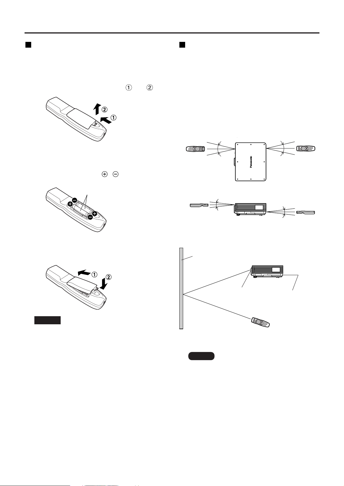
Loading dry cells
When loading batteries into the battery
compartment of the remote control, make sure that
their polarities are correct.
1.Open battery compartment lid.
Open the lid in the order of steps and .
2.Insert the dry cells.
Into battery compartment, with their polarities
orientated as indicated ( , ) in the
compartment.
3.Close the battery compartment lid.
Replace the battery compartment lid over the
compartment and slide until it clicks.
Effective range of remote
control operation
The remote control should normally be aimed at either
the front or rear remote control receiver window on
the projector (figure 1). Otherwise, it may also be
aimed at the screen, which will reflect commands
back to the projector’s front receiver window as
illustrated in figure 2.
The effective control range is approx. 30 m from the
beam receiver on the front or rear.
• Do not drop the remote control unit.
• Do not expose remote control unit to
any liquid.
• Do not use NiCd batteries.
Attention
Note
• When the remote control is aimed at
the screen, the effective control range
may be reduced due to the optical loss
by screen reflection.
• The remote control may not function
properly if an object is in the light path.
• The remote control receiver may not
function properly in intense ambient
light such as fluorescent lamps.
Carefully site the projector so its
remote control receiver windows will
not be directly exposed to intense
light.
Accessory type-AA dry
batteries (insert the negative
side first).
(Front)
(Rear)
[Top view]
Remote
control
Remote
control
30˚
30˚
30˚
30˚
[Side view]
Remote
control
Remote
control
15˚
15˚
15˚
15˚
Remote control
receiver window
(rear)
Remote control
receiver window
(front)
Projector
Remote control
Screen
Figure 1
Figure 2
15
ENGLISH
Setting projector ID number to remote control
Every projector has its ID number and the ID number of the controlling projector must be set to the remote
control in advance so that the user can operate the remote control. The ID number of the projector is set to
“ALL” on shipping, and use the ID ALL button of the remote control when using only a single projector.
Procedure of ID setting
Press the ID SET button, and within five seconds use the number (0 to 9) buttons
to enter the 2-digit ID number set by the projector.
However, if the ID ALL button is pressed, the projector can be controlled regardless of the ID number of the
projector (simultaneous control mode).
• Do not press the ID SET button accidentally or carelessly because the ID number on the remote
control can be set even when no projector is around.
If the ID SET button is pressed, the ID number goes back to the one set before pressing the ID
SET button unless a numeric button is pressed within five seconds after the ID SET button is
pressed.
• Your specified ID number is stored in the remote control unit unless another one is specified later.
However, the stored ID will be erased if the batteries of the remote control are left exhausted.
When the dry cells are replaced, set the same ID number again.
Attention
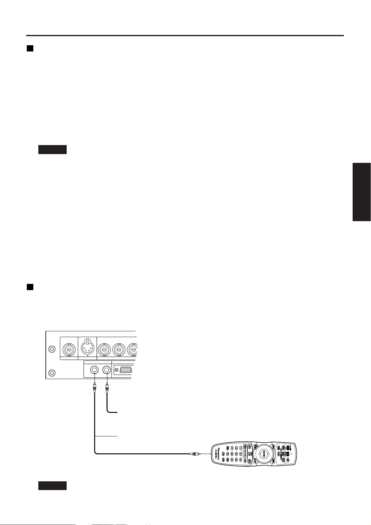
Connect to the projector to use with a cable
When multiple main units are connected in the system, connect the units with the M3 stereo mini jack cable
available in the market to simultaneously control the multiple main units with a single remote control unit through
the REMOTE1 IN/OUT terminal. It is effective to use the wired remote control in the environment in which an
obstacle stands in the light path or where devices are susceptible to outside light.
• Use two-core shielded cable of length smaller than 15 m. If the cable length exceeds 15 m, or if
the shielding of the cable is inadequate, the operation may be unsatisfactory.
Attention
B/P
B
G/Y
R
R/P
REMOTE 1
REMOTE 2 IN
RGB 1 IN
VIDEO IN
S-VIDEO IN
IN OUT
Connect to the
secondary projector
M3 stereo mini jack cable
(available in the market)
16
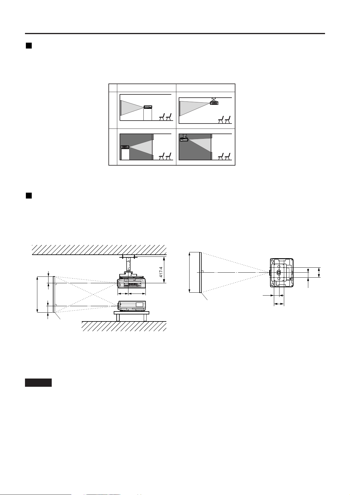
Installation
FRONT
REAR
FLOOR
CEILING
(Default position)
Installation geometry
When planning the projector and screen geometry, refer to the figure below and the information on the next
page for reference. After the projector is roughly positioned, picture size and vertical picture positioning can be
finely adjusted with the powered zoom lens and lens tilt mechanism.
Side view
With optional ceiling mount
bracket (ET-PKD56H)
256
H
H
Screen
SH
185
L
L
;
;
417-497
Top view
200
100
200
100
L
Screen
SW
L : Projection distance
SH : Image height
SW : Image width
H : Distance from centre of lens to bottom edge
of projected image.
• Do not place or use one projector on top of another projection unit.
• Leave a clearance of at least 50 cm so that the ventilation opening on the rear panel will not be
blocked. (page 62)
Attention
Projection schemes
Any of the following four projection schemes can be used depending on user’s needs or viewing conditions.
Use “OPTION2” menu (chosen from the MAIN MENU) to choose the appropriate projection scheme. (page 36)
unit : mm
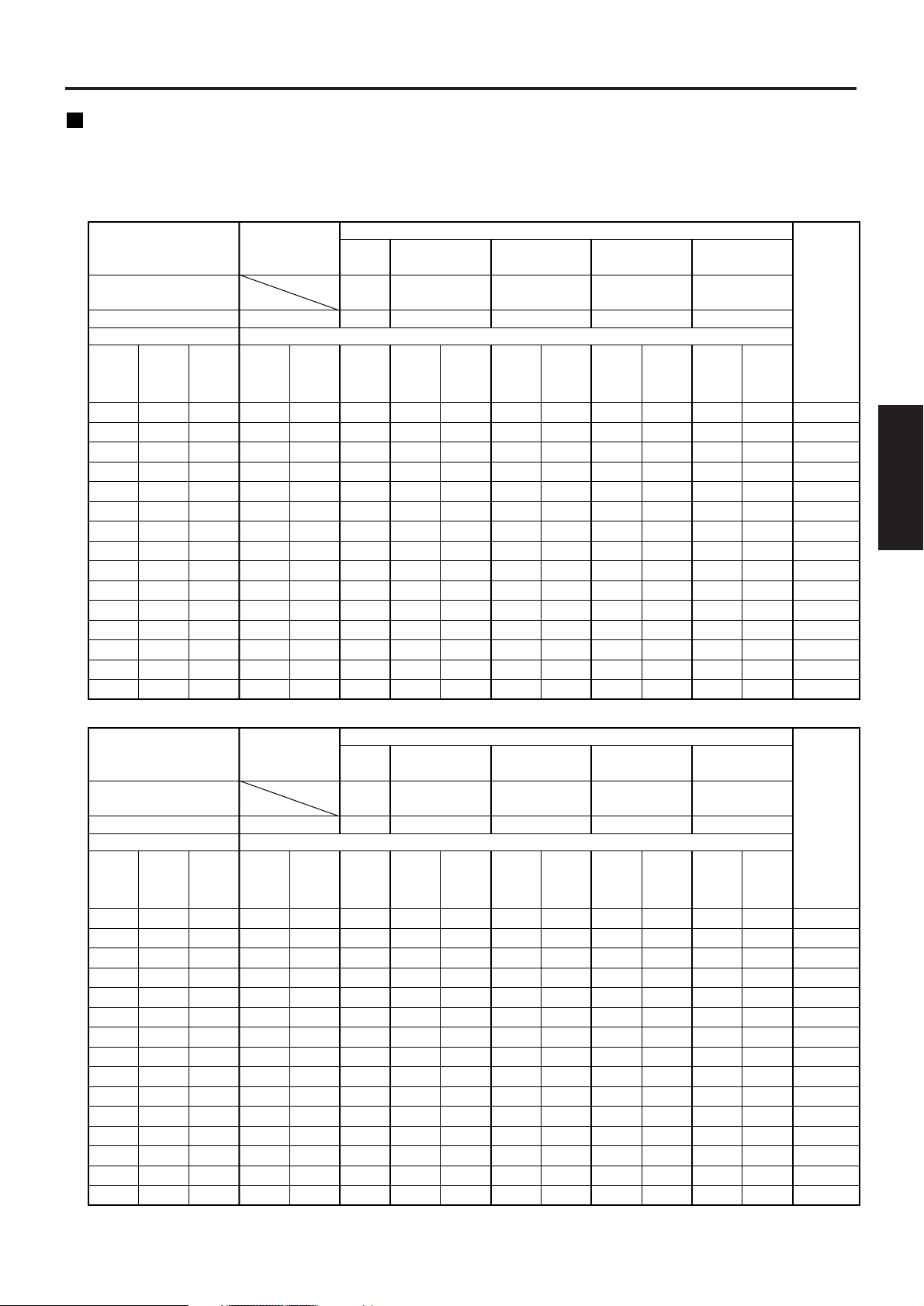
17
ENGLISH
50
60
70
80
90
100
120
150
200
250
300
350
400
500
600
Diagonal
length
(SD)
0.76
0.91
1.07
1.22
1.37
1.52
1.83
2.29
3.05
3.81
4.57
5.33
6.10
7.62
9.14
Height
(SH)
1.02
1.22
1.42
1.63
1.83
2.03
2.44
3.05
4.06
5.08
6.10
7.11
8.13
10.16
12.19
Width
(SW)
1.33
1.61
1.89
2.16
2.44
2.71
3.27
4.09
5.47
6.85
8.23
9.61
10.99
13.75
16.51
Minimum
(LW)
1.81
2.18
2.56
2.93
3.30
3.67
4.42
5.53
7.39
9.25
11.11
12.97
14.83
18.55
22.27
Maximum
(LT)
1.79
2.16
2.53
2.90
3.27
3.64
4.38
5.49
7.34
9.19
11.04
12.89
14.74
18.44
22.14
Minimum
(LW)
2.38
2.86
3.35
3.84
4.33
4.82
5.79
7.26
9.70
12.14
14.58
17.02
19.46
24.34
29.22
Maximum
(LT)
3.84
4.63
5.43
6.22
7.02
7.81
9.40
11.79
15.76
19.74
23.71
27.69
31.66
39.61
47.56
Minimum
(LW)
6.03
7.26
8.49
9.73
10.96
12.19
14.65
18.35
24.51
30.67
36.83
42.99
49.15
61.47
73.79
Maximum
(LT)
0.79
0.96
1.13
1.29
1.46
1.62
1.96
2.45
3.28
—
—
—
—
—
—
ETDLE050
Model number of
projection lens
Projection screen size
Throw ratio*
1
Projection distance (L)
Lens type
Wide-angle
zoom lens
ET-DLE100
Standard
zoom lens
2.45
2.96
3.46
3.97
4.47
4.97
5.98
7.49
10.01
12.53
15.05
17.57
20.09
25.13
30.17
Minimum
(LW)
4.04
4.87
5.69
6.52
7.34
8.16
9.81
12.28
16.40
20.52
24.64
28.76
32.88
41.12
49.36
Maximum
(LT)
Intermediate-focus
zoom lens
ET-DLE200
Optional lens
Long-focus
zoom lens
ET-DLE300
Wide-angle
fixed-focus
lens
(L)
(0.8:1) (1.3–1.8:1)(1.8–2.4:1) (2.4–4.0:1) (3.8–6.0:1)
5.90
7.08
8.26
9.43
10.61
11.78
14.14
17.66
23.54
29.42
35.30
41.18
47.06
58.82
70.58
Minimum
(LW)
8.30
9.94
11.59
13.23
14.88
16.53
19.82
24.76
32.99
41.22
49.45
57.68
65.91
82.37
98.83
0 - 0.38
0 - 0.46
0 - 0.53
0 - 0.61
0 - 0.69
0 - 0.76
0 - 0.91
0 - 1.14
0 - 1.52
0 - 1.91
0 - 2.29
0 - 2.67
0 - 3.05
0 - 3.81
0 - 4.57
Maximum
(LT)
Ultra-long-focus
zoom lens
ET-DLE400
Height
position:
H*
2
(5.8–8.1:1)
(Unit : m
SD : inch)Screen aspect ratio 4:3
Diagonal
length
(SD)
Height
(SH)
Width
(SW)
Minimum
(LW)
Maximum
(LT)
Minimum
(LW)
Maximum
(LT)
Minimum
(LW)
Maximum
(LT)
ETDLE050
Model number of
projection lens
Projection screen size
Throw ratio*
1
Projection distance (L)
Lens type
Wide-angle
zoom lens
ET-DLE100
Standard
zoom lens
Minimum
(LW)
Maximum
(LT)
Intermediate-focus
zoom lens
ET-DLE200
Optional lens
Long-focus
zoom lens
ET-DLE300
Wide-angle
fixed-focus
lens
(L)
Minimum
(LW)
Maximum
(LT)
Ultra-long-focus
zoom lens
ET-DLE400
Height
position:
H*
2
(Unit : m SD : inch)Screen aspect ratio 16:9
50
60
70
80
90
100
120
150
200
250
300
350
400
500
600
0.62
0.75
0.87
1.00
1.12
1.25
1.49
1.87
2.49
3.11
3.74
4.36
4.98
6.23
7.47
1.11
1.33
1.55
1.77
1.99
2.21
2.66
3.32
4.43
5.53
6.64
7.75
8.86
11.07
13.28
1.46
1.76
2.06
2.36
2.66
2.96
3.57
4.47
5.97
7.48
8.98
10.49
11.99
15.00
18.01
1.95
2.35
2.76
3.16
3.56
3.97
4.77
5.98
8.00
10.01
12.03
14.04
16.06
20.09
24.12
2.60
3.13
3.66
4.19
4.72
5.26
6.32
7.92
10.58
13.24
15.90
18.56
21.22
26.54
31.86
0.87
1.05
1.23
1.41
1.59
1.77
2.14
2.68
3.58
—
—
—
—
—
—
1.98
2.38
2.79
3.19
3.60
4.00
4.81
6.03
8.05
10.08
12.10
14.13
16.15
20.20
24.25
4.19
5.06
5.92
6.79
7.66
8.52
10.25
12.85
17.18
21.51
25.84
30.17
34.50
43.16
51.82
6.58
7.92
9.26
10.61
11.95
13.29
15.97
20.00
26.71
33.42
40.13
46.84
53.55
66.97
80.39
2.68
3.23
3.78
4.33
4.88
5.42
6.52
8.17
10.91
13.66
16.40
19.15
21.89
27.38
32.87
4.41
5.31
6.21
7.11
8.01
8.90
10.70
13.39
17.88
22.37
26.86
31.35
35.84
44.82
53.80
6.43
7.71
8.99
10.27
11.55
12.83
15.40
19.24
25.64
32.05
38.45
44.86
51.26
64.07
76.88
9.03
10.82
12.62
14.41
16.20
18.00
21.58
26.96
35.93
44.89
53.86
62.82
71.79
89.72
107.65
–0.10 - 0.31
–0.12 - 0.37
–0.15 - 0.44
–0.17 - 0.50
–0.19 - 0.56
–0.21 - 0.62
–0.25 - 0.75
–0.31 - 0.93
–0.42 - 1.25
–0.52 - 1.56
–0.62 - 1.87
–0.73 - 2.18
–0.83 - 2.49
–1.04 - 3.11
–1.25 - 3.74
(0.8:1) (1.3–1.8:1)(1.8–2.4:1) (2.4–4.0:1) (3.8–6.0:1) (5.8–8.1:1)
*1The throw ratio is based on the value during projection onto an 80-inch screen size.
*2Lens shift is not available when using the ET-DLE050, and so the height position (H) is SH/2.
Projection distance by projection lens
Listed in the table below are the lens projection distances for the PT-D5700E (lens included), PT-D5700EL (lens
sold separately), PT-DW5100E (lens included) and PT-DW5100EL (lens sold separately).
• PT-D5700E, PT-D5700EL
18
Installation
5.08
6.13
7.17
8.21
9.26
10.30
12.39
15.52
20.74
25.96
31.18
36.40
41.62
52.06
62.50
9.62
11.57
13.52
15.47
17.42
19.37
23.28
29.13
38.88
48.64
58.39
68.15
77.90
97.41
116.92
Diagonal
length
(SD)
Height
(SH)
Width
(SW)
Minimum
(LW)
Maximum
(LT)
Minimum
(LW)
Maximum
(LT)
Minimum
(LW)
Maximum
(LT)
ETDLE050
Model number of
projection lens
Projection screen size
Throw ratio*
1
Projection distance (L)
Lens type
Wide-angle
zoom lens
ET-DLE100
Standard
zoom lens
Minimum
(LW)
Maximum
(LT)
Intermediate-focus
zoom lens
ET-DLE200
Optional lens
Long-focus
zoom lens
ET-DLE310
Wide-angle
fixed-focus
lens
(L)
(0.8:1) (1.4–1.8:1)(1.8–2.4:1) (2.5–4.1:1) (3.5–4.7:1)
Minimum
(LW)
Maximum
(LT)
Ultra-long-focus
zoom lens
ET-DLE410
Height
position:
H*
2
(4.7–8.9:1)
(Unit : m
SD : inch)Screen aspect ratio 15:9
50
60
70
80
90
100
120
150
200
250
300
350
400
500
600
0.65
0.78
0.91
1.05
1.18
1.31
1.57
1.96
2.61
3.27
3.92
4.57
5.23
6.53
7.84
1.09
1.31
1.52
1.74
1.96
2.18
2.61
3.27
4.36
5.45
6.53
7.62
8.71
10.89
13.07
1.45
1.75
2.05
2.35
2.65
2.95
3.55
4.45
5.95
7.45
8.95
10.45
11.95
14.95
17.95
1.97
2.38
2.78
3.18
3.59
3.99
4.80
6.01
8.03
10.05
12.07
14.09
16.11
20.15
24.19
1.95
2.35
2.75
3.15
3.55
3.96
4.76
5.97
7.98
9.99
12.00
14.01
16.02
20.04
24.06
2.59
3.12
3.65
4.18
4.71
5.24
6.30
7.89
10.54
13.19
15.84
18.49
21.14
26.44
31.74
3.82
4.61
5.40
6.18
6.97
7.75
9.33
11.68
15.61
19.54
23.47
27.40
31.33
39.19
47.05
5.02
6.05
7.08
8.10
9.13
10.15
12.21
15.28
20.41
25.54
30.67
35.80
40.93
51.19
61.45
0.86
1.04
1.22
1.40
1.58
1.76
2.12
2.66
3.56
—
—
—
—
—
—
2.67
3.22
3.76
4.31
4.86
5.40
6.50
8.14
10.87
13.61
16.34
19.08
21.81
27.28
32.75
4.40
5.29
6.19
7.08
7.98
8.87
10.66
13.35
17.82
22.30
26.77
31.25
35.72
44.67
53.62
–0.09 - 0.33
–0.10 - 0.39
–0.12 - 0.46
–0.14 - 0.52
–0.16 - 0.59
–0.17 - 0.65
–0.21 - 0.78
–0.26 - 0.98
–0.35 - 1.31
–0.44 - 1.63
–0.52 - 1.96
–0.61 - 2.29
–0.70 - 2.61
–0.87 - 3.27
–1.05 - 3.92
5.17
6.23
7.29
8.35
9.41
10.47
12.59
15.78
21.08
26.39
31.69
37.00
42.30
52.91
63.52
9.78
11.76
13.75
15.73
17.71
19.69
23.66
29.61
39.52
49.44
59.35
69.27
79.18
99.01
118.84
Diagonal
length
(SD)
Height
(SH)
Width
(SW)
Minimum
(LW)
Maximum
(LT)
Minimum
(LW)
Maximum
(LT)
Minimum
(LW)
Maximum
(LT)
ETDLE050
Model number of
projection lens
Projection screen size
Throw ratio*
1
Projection distance (L)
Lens type
Wide-angle
zoom lens
ET-DLE100
Standard
zoom lens
Minimum
(LW)
Maximum
(LT)
Intermediate-focus
zoom lens
ET-DLE200
Optional lens
Long-focus
zoom lens
ET-DLE310
Wide-angle
fixed-focus
lens
(L)
Minimum
(LW)
Maximum
(LT)
Ultra-long-focus
zoom lens
ET-DLE410
Height
position:
H*
2
(Unit : m SD : inch)Screen aspect ratio 16:9
50
60
70
80
90
100
120
150
200
250
300
350
400
500
600
0.62
0.75
0.87
1.00
1.12
1.25
1.49
1.87
2.49
3.11
3.74
4.36
4.98
6.23
7.47
1.11
1.33
1.55
1.77
1.99
2.21
2.66
3.32
4.43
5.53
6.64
7.75
8.86
11.07
13.28
1.48
1.78
2.09
2.39
2.70
3.00
3.61
4.53
6.05
7.58
9.10
10.63
12.15
15.20
18.25
2.01
2.42
2.83
3.24
3.65
4.06
4.88
6.12
8.17
10.23
12.28
14.34
16.39
20.50
24.61
1.98
2.39
2.80
3.21
3.62
4.03
4.84
6.07
8.12
10.16
12.21
14.25
16.30
20.39
24.48
2.63
3.17
3.71
4.25
4.79
5.33
6.40
8.02
10.72
13.41
16.11
18.80
21.50
26.89
32.28
3.89
4.69
5.49
6.29
7.08
7.88
9.48
11.88
15.87
19.87
23.86
27.86
31.85
39.84
47.83
5.11
6.15
7.20
8.24
9.28
10.32
12.41
15.54
20.75
25.97
31.18
36.40
41.61
52.04
62.47
0.88
1.06
1.24
1.43
1.61
1.79
2.16
2.71
3.62
—
—
—
—
—
—
2.71
3.27
3.83
4.38
4.94
5.49
6.61
8.27
11.05
13.83
16.61
19.39
22.17
27.73
33.29
4.47
5.38
6.29
7.20
8.11
9.02
10.84
13.57
18.12
22.67
27.22
31.77
36.32
45.42
54.52
–0.11 - 0.31
–0.13 - 0.37
–0.15 - 0.44
–0.17 - 0.50
–0.20 - 0.56
–0.22 - 0.62
–0.26 - 0.75
–0.33 - 0.93
–0.44 - 1.25
–0.55 - 1.56
–0.66 - 1.87
–0.77 - 2.18
–0.87 - 2.49
–1.09 - 3.11
–1.31 - 3.74
(0.8:1) (1.4–1.8:1)(1.8–2.4:1) (2.5–4.1:1) (3.5–4.7:1) (4.7–8.9:1)
*1The throw ratio is based on the value during projection onto an 80-inch screen size.
*2Lens shift is not available when using the ET-DLE050, and so the height position (H) is SH/2.
• PT-DW5100E, PT-DW5100EL
Standard
zoom lens
Wide-angle fixedfocus lens
Wide-angle
zoom lens
Intermediate-focus
zoom lens
Long-focus
zoom lens
Ultra-long-focus
zoom lens
Model No. :
ET-DLE050
Model No. :
ET-DLE100
Model No. :
ET-DLE200
Model No. :
ET-DLE300
Model No. :
ET-DLE400
4:3
16:9
4:3
16:9
4:3
16:9
4:3
16:9
4:3
16:9
4:3
16:9
Minimum (LW)
Maximum (LT)
Minimum (LW)
Maximum (LT)
Minimum (LW)
Maximum (LT)
Minimum (LW)
Maximum (LT)
Minimum (LW)
Maximum (LT)
Minimum (LW)
Maximum (LT)
Minimum (LW)
Maximum (LT)
Minimum (LW)
Maximum (LT)
Minimum (LW)
Maximum (LT)
Minimum (LW)
Maximum (LT)
L=0.0370 x SD-0.0650
L=0.0488 x SD-0.0638
L=0.0403 x SD-0.0650
L=0.0532 x SD-0.0638
L=0.0166 x SD-0.0361
L=0.0181 x SD-0.0361
L=0.0276 x SD-0.0452
L=0.0372 x SD-0.0478
L=0.0301 x SD-0.0452
L=0.0405 x SD-0.0478
L=0.0504 x SD-0.0657
L=0.0824 x SD-0.0758
L=0.0549 x SD-0.0657
L=0.0898 x SD-0.0758
L=0.0795 x SD-0.1380
L=0.1232 x SD-0.1310
L=0.0866 x SD-0.1380
L=0.1342 x SD-0.1310
L=0.1176 x SD+0.0244
L=0.1646 x SD+0.0651
L=0.1281 x SD+0.0244
L=0.1793 x SD+0.0651
(L, LW, LT : m SD : inch)
Lens type Aspect ratio Projection distance (L) formula
Standard
zoom lens
Wide-angle fixedfocus lens
Wide-angle
zoom lens
Intermediate-focus
zoom lens
Long-focus
zoom lens
Ultra-long-focus
zoom lens
Model No. :
ET-DLE050
Model No. :
ET-DLE100
Model No. :
ET-DLE200
Model No. :
ET-DLE310
Model No. :
ET-DLE410
15:9
16:9
15:9
16:9
15:9
16:9
15:9
16:9
15:9
16:9
15:9
16:9
Minimum (LW)
Maximum (LT)
Minimum (LW)
Maximum (LT)
Minimum (LW)
Maximum (LT)
Minimum (LW)
Maximum (LT)
Minimum (LW)
Maximum (LT)
Minimum (LW)
Maximum (LT)
Minimum (LW)
Maximum (LT)
Minimum (LW)
Maximum (LT)
Minimum (LW)
Maximum (LT)
Minimum (LW)
Maximum (LT)
L=0.0402 x SD-0.0650
L=0.0530 x SD-0.0638
L=0.0409 x SD-0.0650
L=0.0539 x SD-0.0638
L=0.0180 x SD-0.0361
L=0.0183 x SD-0.0361
L=0.0300 x SD-0.0452
L=0.0404 x SD-0.0478
L=0.0305 x SD-0.0452
L=0.0411 x SD-0.0478
L=0.0547 x SD-0.0657
L=0.0895 x SD-0.0758
L=0.0556 x SD-0.0657
L=0.0910 x SD-0.0758
L=0.0786 x SD-0.1062
L=0.1026 x SD-0.1056
L=0.0799 x SD-0.1062
L=0.1043 x SD-0.1056
L=0.1044 x SD-0.1374
L=0.1951 x SD-0.1352
L=0.1061 x SD-0.1374
L=0.1983 x SD-0.1352
(L, LW, LT : m SD : inch)
Lens type Aspect ratio Projection distance (L) formula
19
ENGLISH
Calculation formulas for projection distance by lens types
• PT-D5700E, PT-D5700EL
• PT-DW5100E, PT-DW5100EL
Note
• The dimensions in the table in pages 17-18 and the values obtained from the above formulas may
contain slight errors.
• When an SXGA signal is input and projected, the right and left ends of the picture will be blanked
and the aspect ratio will be 5:4.
• The brightness is different between the wide lens position settings and telephoto lens position
settings.
20
Connection
Setup precautions
• Before connecting any of your video/audio equipment to the projector, carefully read the owners manual
supplied with the equipment once again.
• All cable connections should be made with the entire system devices, including the projector, first turned off.
• Obtain commercial interconnecting cables for devices supplied with no accessory or optional interconnect
cables.
• Video signals containing too much jitter may cause the images on the screen to randomly wobble or shake.
Inserting a time base corrector (TBC) in the projector’s video line will relieve this problem.
• The projector only accepts composite-video, S-Video, analogue-RGB (with TTL sync. level) and digital signal.
• Some PC models are not compatible with PT-D5700E/PT-D5700EL/PT-DW5100E/PT-DW5100EL projectors.
• When using long cables to connect various equipment to the projector, there is a possibility that the image will
not be output correctly unless a compensator is used.
• The pin assignments on the S-VIDEO IN terminal are
as follows:
• The pin assignments on the DVI-D input terminal
are as follows (interface with DVI-D output
terminal on PC):
• The pin assignments on the RGB2 input terminal are
as follows:
Viewed from mating side
Pin No.
Signal
Ground (luminance)
Ground (colour)
Luminance signal
Colour signal
Pin : Not used.
Pins - , and : Ground
Viewed from mating side
Signal
R/P
R
G/G · SYNC/Y
B/P
B
HD/SYNC
VD
Pin No.
Viewed from mating side
Pin No.
Signal
T. M. D. S data 2–
T. M. D. S data 2+
T. M. D. S data 2
shield
DDC clock
DDC data
T. M. D. S data 1–
T. M. D. S data 1+
T. M. D. S data 1
shield
Signal
+5 V
Ground
Hot plug sense
T. M. D. S data 0–
T. M. D. S data 0+
T. M. D. S data 0
shield
T. M. D. S clock
shield
T. M. D. S clock+
T. M. D. S clock–
Pin No.
• The DVI-D input terminal supports single link only.
• EDID settings may be needed depending on the DVI
equipment being connected. (page 35)
• The DVI-D input terminal can be used to connect to a
DVI equipment, but note that images may not appear
or the projector may not work properly when
connected to certain DVI equipment.
• This projector supports HDCP.
 Loading...