

Panasonic PT-51D31CE, PT-61D31CE Service Manual
ORDER NO. MTNC010420A1
B2
Service Manual
Color Video Projection System
S
m
i
p
l
i
f
i
e
d
Simplified Manual
P6
Panasonic
Models
PT-51D31CE AP821
PT-61D31CE AP821
Chassis
Note: Refer to Technical Guide (P6) for
functional descriptio ns and Bloc k Diag rams .
(MTNC010308G1).
This Simplified Se rvice Manual is issued to add listed model to the Main Ser vice Manual order No. MTNC010 307C1
(PT-51G36E). A full set of schematics, disassembly procedures, and a complete parts list are included in this Simplified
Manual. Please file and use this manual together with Main Service Manual, order No. MTNC010307C1 (PT-51G36E).
“WARNING! This Service Manual is desig ned for expe rienced repa ir technici ans only and is not de signed for u se by the general pub lic.
It does not contain warnings or cautions to advise non-technical individuals of potential dangers in attempting to service a product.
Products powered by electricity should be serviced or repai red only by exp erienced profe ssional techn icians. Any attemp t to
service or repair the product or products dealt with in this Service Manual by anyone else could result in serious injury or death.”
The service technician is required to read and follow the “Safety Precautions” and “Important Safety Notice” in this Manual.
Copyright 2001 by Matsushita Electric Corporation of
America. All rights reserved. Unauthorized copying
and distribution is a violation of law.
Service Mode (Electronic Controls)
To toggle between Aging and Service
modes:
While the “CHK” is di splayed on the left top corner
of the Screen, pressing “ACTION” and “VOL UP” on
the PTV simultaneously toggles between the
modes. Red “CHK” for Service and yellow “CHK” for
Aging.
This PTV has electronic techno logy using the I²C Bus
Concept. It performs as a control function and it
replaces many mechanical controls. Instead of
adjusting mechanical controls indivi dually, many of the
control functions are now performed by using “On
Screen Display Menu”. (The Service Adjustment
Mode.)
Note: It is suggested that the techni cian r eads al l the
way through and understand the following
procedure for Entering/Exiting the Service
Adjustment Mode and then proceed with the
instructions working with the PTV.
Quick Entry to Service Mode:
When minor adjustments need to be done to the
electronic controls, the me thod of Entering the S ervice
Mode without removal of th e cabi net bac k is as fo llows
using the Remote Control:
1. Select SET-UP icon and select CABLE mode.
2. Select TIMER icon and set SLEEP time for 30 Min.
3. Press “ACTION” twice to exit menus.
4. Tune to the Channel 124.
5. Adjust VOLUME to minimum (0).
6. Press VOL (decrease) on PTV. Red “CHK”
appears in upper corner.
8. “CHK” = Normal operation of CHANNEL
and VOLUME .
b
32 B 0 2 215 C 0
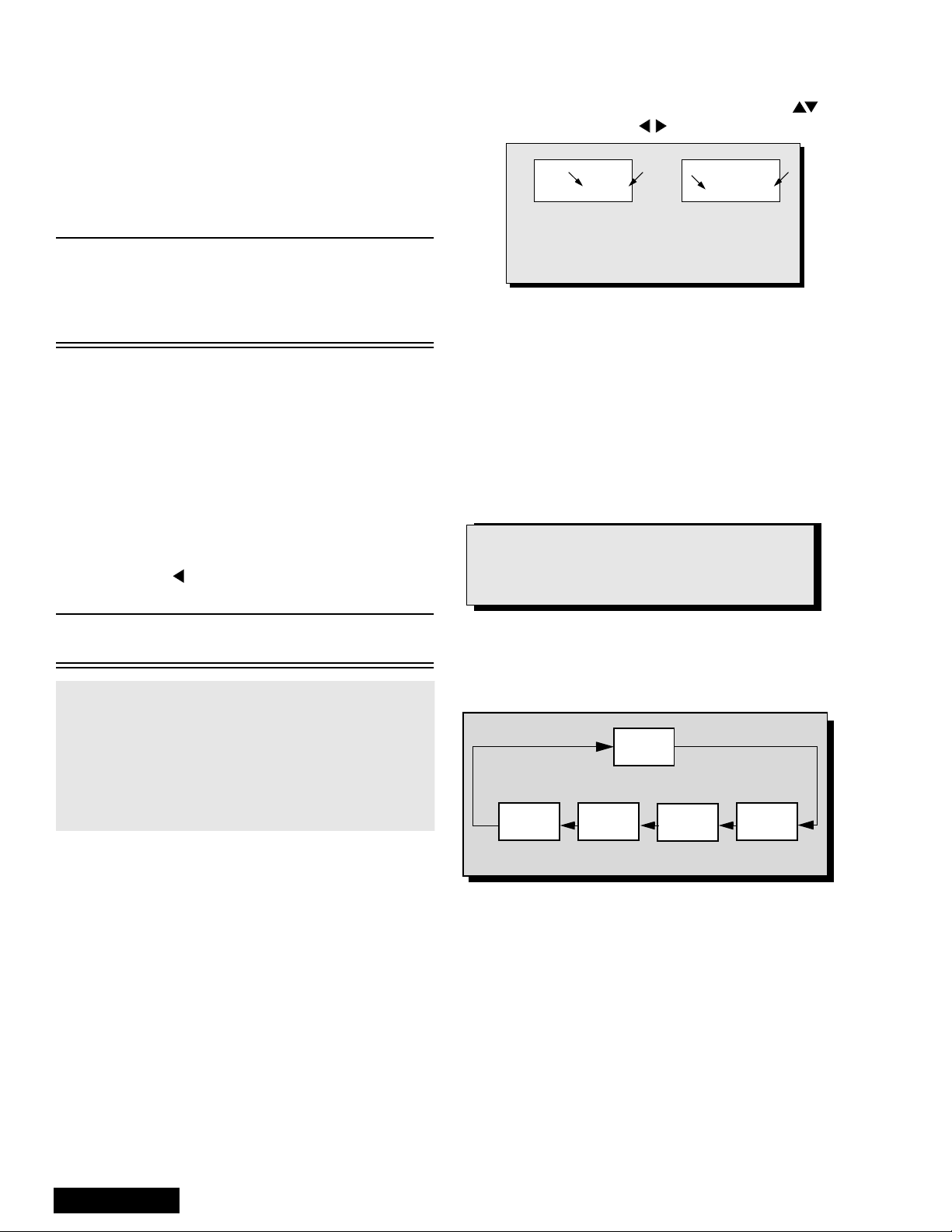
An address Menu appears in the right
hand corner of the screen
a
b
a
Figure 7. Service Mode Menu Adjustments.
Exiting the Service Mode:
Press “ACTION” and “POWER” on the PTV
simultaneously for at least 2 second s.
THE PTV EXITS SERVICE MODE.
The PTV momentarily shuts off; then comes back on
tuned to channel 3 with a preset level of audio.
Any programmed c hannel s, ch annels capt ion data an d
some others user defined settings will be erased.
NOTE
Always Exit the Service Mode
Following Adjustments.
Note: After PTV is set into SERVICE mode, set
TIMER back to NO.
7. Press “POWER” on the Remote Control to select
one of the Service Adjustment Modes.
1. B= Service VCJ SUB-DATA Adjustment s.
2. C= Service VCJ CUT-OFF Adjustments.
3. D= Service PINCUSHION Adjustments.
4. P= Servic e PIP Adjustments.
5. S =Service S OPTION Adjustments.
6. X =Service X OPTION Adjustments.
7. V= Service Y OPTION Adjustments.
To Check Purity:
Press “RECALL” on the Remote Control when in
Service Mode (red “CHK” is displayed) to enter the
Purity Field Check Mode.
NORMAL
SCREEN
Press “RECALL” again to select desired field.
BLUE
SCREEN
GRN.
SCREEN
RED
SCREEN
Figure 8. Purity Check Field Mode.
WHITE
SCREEN
Service Manual
- 10 -
Note: Registers marked as FIXED are factory preset.
The default value must not be changed.
Important Note:
Write down the original values (“b” in the
adjustment mode details, Fig. 7) for each address
adjustment before modifying values.
Follow the procedure bel ow to access various Servic e
adjustments. (Same procedures apply to each section.)
a. Press CH on the Remote Control to select
any of the seven Service Sub Adjustment
Addresses. (“a” in Fig. 7.)
b. Press on the Remote Control to adjust
the level of the selected Service Adj ustments.
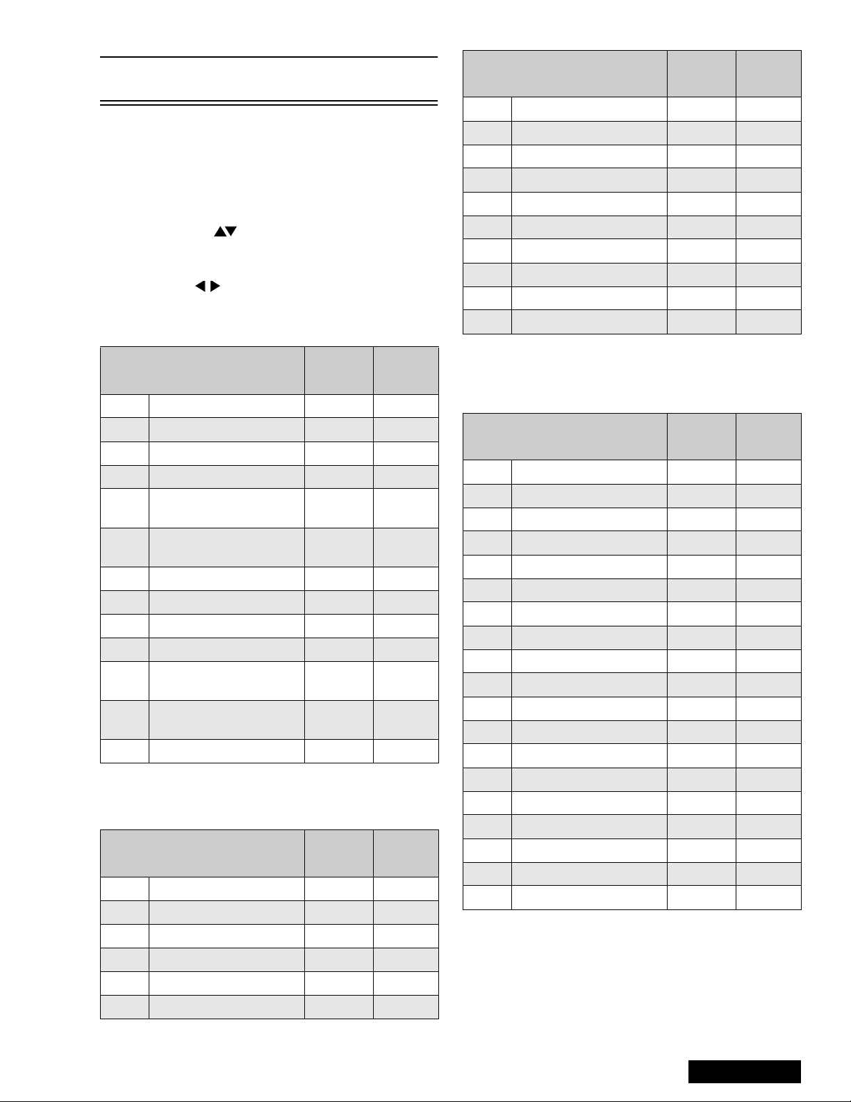
B Items: Service Sub Adjustments
Service Adjustment
B00 Sub B rightness 0 ~ 127 44
B01 Sub Contrast (RF) 0 ~ 15 5
B02 Sub C olor 0 ~ 63 18
B03 Sub Tint 0 ~ 63 34
B04
B05
B06 Sub Color (Video) FIXED 127
B07 Sub Tint (Video) FIXED 127
B08 Sub C olor (Component) FIXED 127
B09 Sub Tint (Component) FIXED 75
B0A
B0B
B0C Sub Contrast ---- ----
Sub Brightness
(Video/Component)
Sub Contrast
(Video/Component)
Sub Sharpness
(RF/Video)
Sub Sharpness
(Component)
Adj.
Range
FIXED 127
FIXED 16
FIXED 15
FIXED 20
Table 3: Ser vi ce Adj. B00 ~ B0C
Default
Level
Service Adjustment
C06 G CutOff (Video) FIXED 127
C07 B CutOff (Video) FIXED 127
C08 G Drive (Video) FIXED 127
C09 B Drive (Video) FIXED 127
C0A G CutOff (Component) FIXED 127
C0B B CutOff (Component) FIXED 127
C0C G Drive (Component) FIXED 127
C0D B Drive (Component) FIXED 127
C0E Drive Color Temp. FIXED 8
C0F Contrast Color Temp. FIXED 5
Adj.
Range
Default
Level
Table 4: Service Adj. C00 ~ C0F (Continued)
D Items: Pincushion Adjustments
Service Adjustment
D00 Vertical Amplitude 0 ~ 30 20
D01 Vertical Linearity 0 ~ 15 13
D02 Vertical S Correction 0 ~ 7 6
D03 Horizontal Amplitude 0 ~ 63 30
D04 Horizontal Centering 0 ~ 31 17
D05 EW Parabola 0 ~ 31 6
D06 Trapezoid 0 ~ 15 5
D07 EW Corner 2 0 ~ 15 8
D08 H EHT Correction 0 ~ 255 8
D09 Vertical Amplitude FIXED 3
D0A V BLK Start Phase FIXED 12
D0B V BLK Stop Phase FIXED 14
D0C V AGC FIXED 1
D0D Vertical Cente r in g FIXED 63
Adj.
Range
Default
Level
C Items: VCJ Cutoff Adjustments
Service Adjustment
C00 R Cutoff 0 ~ 255 128
C01 G Cutoff (RF) 0 ~ 255 128
C02 B Cutoff 0 ~ 255 129
C03 Brightness FIXED 31
C04 G Drive (RF) 0 ~ 127 65
C05 B Drive (RF) 0 ~ 127 66
Adj.
Range
Table 4: Service Adj. C00 ~ C0F
Default
Level
D0E V Cent. DAC SW FIXED 0
D0F Conver. FIXED 0
D10 Free Run ON/OFF FIXED 0
D11 V Size Off Set FIXED 2
D12 V Lin Off Set FIXED 8
Table 5: Service Adj. D0 0 ~ D12
- 11 -
Service Manual
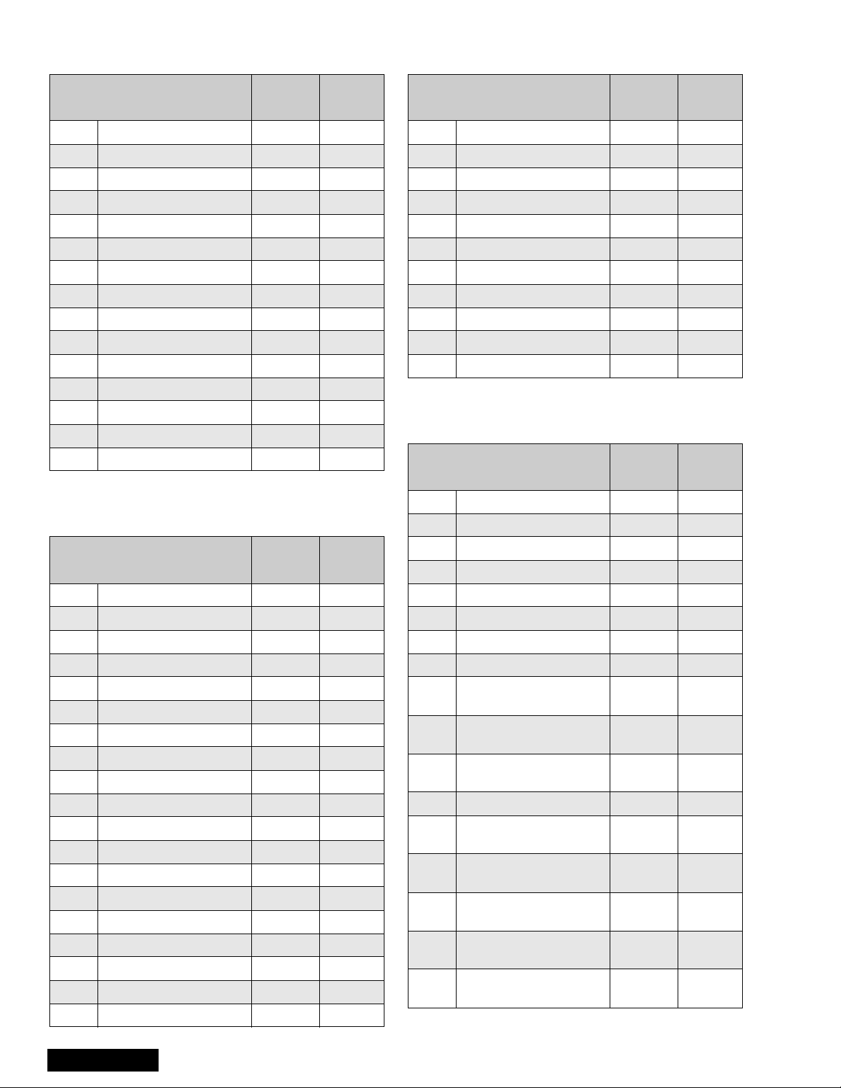
P Items: PIP Adjustments
X Option Items
Service Adjustment
P00 PIP Color FIXED 92
P01 PIP Tint FIXED 54
P02 PIP Brightness 0 ~ 31 22
P03 PIP Contrast 0 ~ 12 7 80
P04 PIP V Position 9 Up FIXED 27
P05 PIP V Position 9 Down FIXED 143
P06 PIP H Position 9 Left FIXED 12
P07 PIP H Position 9 Right FIXED 103
P08 PIP V Position 16 Up FIXED 27
P09 PIP V Posit 16 Down FIXED 161
P0A PIP H Position 16 Left FIXED 12
P0B PIP H Position 16 Right FIXED 118
P0C PIP Freerun ---- ---P0D PIP Y Delay FIXED 4
P0E PIP BG Start FIXED 17
Adj.
Range
Default
Level
Table 6: Service Adj. P00 ~ P0E
S Option Items
Service Adjustment
X00 Clip Level FIXED 8
X01 Correct Gain ---- ---X02 Limit Level FIXED 24
X03 Core Level FIXED 41
X04 C Delay (RF) FIXED 2
X05 C Delay (Video) FIXED 5
X06 VM Limit Level FIXED 90
X07 VM Core Level FIXED 8
X08 Sharpness FIXED 50
X09 VM Limit Level A FIXED 255
X0A VM Freq. SW FIXED 1
Adj.
Range
Default
Level
Table 8: Service Adj. X00 ~ X0A
V Option Adjustments
Service Adjustment
V00 Static Conv. Mode ---- ---V01 Point Conv . Mo de ---- ----
Adj.
Range
Default
Level
Service Adjustment
S00 B.S. Point FIXED 7
S01 RGB Gamma FIXED 1
S02 Col Gamma FIXED 0
S03 ABL Gain FIXED 2
S04 ABL Point FIXED 0
S05 RGB Brightness FIXED 10
S06 MTS Input Level 0 ~ 63 33
S07 MTS Low Separation 0 ~ 63 8
S08 MTS H i gh Separatio n 0 ~ 63 30
S09 Clock Adjustment 0 ~ 255 128
S0A Loudness Comp FIXED 7
S0B Caption Digital Filter SW FIXED 1
S0C Caption Scroll FIXED 1
S0D RGB MTX (RF/Video) FIXED 6
S0E RGB MTX (Component) FIXED 5
S0F BBE ON/OFF FIXED 1
S10 BBE Low Level FIXED 4
S11 BBE High Level FIXED 6
S12 Surround Effect FIXED 3
Adj.
Range
Default
Level
Table 7: Serviceman Adj. S00 ~ S12
Service Manual
V02 DAF Mode ---- ---V03 DAF ON/OFF FIXED 0
V04 ABL Input Level FIXED 10
V05 Blue Gamma FIXED 0
V06 VM ON/OFF FIXED 0
V07 ABL ON/OFF FIXED 0
V08
V09
V0A
V0B V1 Delay 0 ~ 255 1
V0C
V0D
V0E
V0F
V10
Test Pattern
Vertic al Phas e
Test Pattern
Vertical OSD
Test Pattern
Horizontal OSD
User St at ic Data
(Vertical, Red)
User St at ic Data
(Vertical, Green)
User St at ic Data
(Vertical, Blue)
User St at ic Data
(Horizon, Red)
User St at ic Data
(Horizon, Green)
0 ~ 255 20
0 ~ 255 29
0 ~ 255 65
FIXED 100
FIXED 100
FIXED 100
FIXED 100
FIXED 100
Table 9: Service Adj. V00 ~ V15
- 12 -
Service Adjustment
V1 1
V12
V13
V14
V15 Start Line (LOW) FIXED 11
User Static Data
(Horizon, Blue)
Test Pattern Horizon t al
Phase (LOW)
Test Pattern Fine
Horizontal Phase (LOW)
Test Pattern Coarse
Horizontal Phase (LOW)
Adj.
Range
FIXED 100
FIXED 90
FIXED 235
FIXED 0
Default
Level
Table 9: Service Adj. V00 ~ V15 (Continued)
HV_Feedback Voltage (D08)
Procedure:
1. Apply a NTSC all black pattern.
2. Connect meter (+) to TPA38 and (-) to TPA20.
3. Adjust DAC D08 until reading on meter is
5.0V ± 0.2V.
Sub-Bright Adjustment (B00)
Procedure:
1. Normalize picture.
2. Connect meter (+) to TPA18 and (-) to TNPA19.
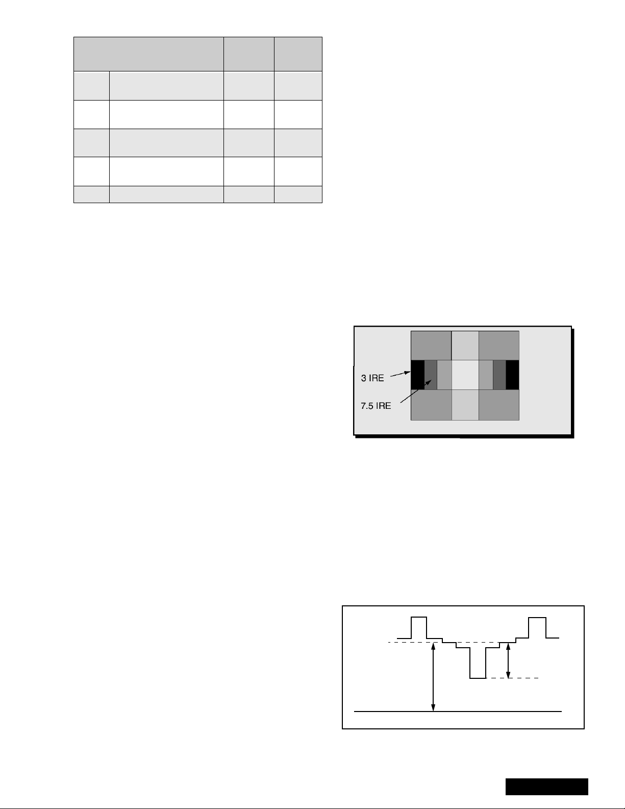
3. Apply a black level pattern.
4. Adjust DAC B00 (Sub-Brightn ess) until reading on
meter is 17.0V ± 1V (7.5 IRE part is same light
output as 3 IRE part. See Fig. 9.
5. Apply a monoscope pattern and adjust bright
control to max. and confirm same reading on
meter.
Contrast Adjustment
Preparation:
1. Set Auto Color and AI Picture to “OFF”.
2. Set the following in the user picture menu as
follows:
COLOR: min. (0)
PICTURE: max (63)
BRIGHT: center (31)
SHARPNESS: min. (0)
Set Cut Off Data:
• DAC C00 (R_CutOff) to 128.
• DAC C01 (G_RF CutOff) to 128.
• DAC C02 (B_CutOff) to 128.
• DAC C06 (G_Video CutOff) to 127.
• DAC C07 (B_Video CutOff) to 127.
• DAC C0A (G_Video Component) to 127.
• DAC C0B (B_Video Component) to 127.
Set Drive Data:
•DAC C04 (
•DAC C05 (B_Drive RF) to 64.
Procedure:
1. Use 100:1 probe for measurements.
2. Apply a black/white pattern. See Fig. 9.
G_Drive RF) to 64.
Figure 9. Black/white Pattern
3. Connect scope to TPLR1 and adjust Sub-Bright
(B00) data until voltage measured is 190V ± 2V.
See Fig. 10.
4. Connect scope to TPLG1 and adjust R-CutOff
(C00) data until voltage measured is 190V ± 2V.
See Fig. 10.
5. Connect scope to TPLB1 and adjust B-CutOff
(C02) data until voltage measured is 190V ± 2V.
See Fig. 10.
6. Connect scope to TPLR1 an d adjust Sub-Co ntrast
(B01) data to obtain 85V ± 2V between black
(7.5 IRE) and White level. See Fig. 10.
7.5 IRE
85V ± 2V (R)
190V±2V (R, G, B)
Use 100:1 Probe
GND
100 IRE
Figure 10. Contrast Adjustment.
- 13 -
Service Manual
Red, Green & Blue Screen Cutoff
1. Use either a no input signal condition or raster from
the NTSC generator.
2. Observing the green tube directly or via a reflective
surface, adjust the VR on the green tube for
minimum noise.
3. Adjust the noise level i n the red and blue tubes to
match the noise level in the green tube.
White Balance Adjustment
Prior to this adjustment, perform Contrast Adjustment.
This adjustment requires that the service technician
use skills in observing what a screen without color
should look like (White Picture).
1. Enter the service mode.
2. Apply a black and white pattern to one of the vi de o
inputs.
High Light White Balance Adjustment
1. Adjust DAC C04 for green and C05 for blue
adjustments.
2. Make sure the screen is not blue or green. The
screen should be white in all areas.
3. Check the black and white pattern for a black and
white picture with even shades of gray and no color
tint in the picture.
Low Light White Balance Adjustment
1. Adjust DAC C01 for green and DAC C02 for blue.
2. Check the screen for even pure white in all areas.
3. Check the black and white pattern for a black and
white picture, even shades of gray and no color tint
in the low light areas.
4. Repeat the High Light and Low Light White
Balance again until the white bal ance tracks from
high light to low light.
Tint and Color Check
Again, the service technician ability to see color and
the balance of color is important for these adjustments.
Tint Check
1. In Picture Menu set Picture Norm to YES.
2. Apply color bars to the video input.
3. Magenta is composed of two colors, blue and red.
4. Check to see that magenta does not have too
much blue or too much red.
5. Check cyan. Cyan is c omposed of blu e and green .
It should not have too much blue or green.
6. Use a test signal from a V CR or la se r dis k that has
a pre-recorded close up of a sign al that has good
flesh tones.
7. The signal on the VCR or laser disk should look
normal.
Color Check
Using a clean RF or video s ignal, s et the col or level so
that it does not sat urate or appear harsh. Make sure
that color is n ot set so that it a ppears du ll and washed
out. Look for natural co lors; try to adjust the pic ture to
appear as a normal photograph.
MTS Circuit Adjustments
Note: It is important to a djust the MTS circuit in th e
order shown below.
The MTS Circuit Adjustments require two steps:
1. Input Level Adjustment.
2. Stereo Separation Adjustment.
Input Level Adjustment (S06)
Preparation:
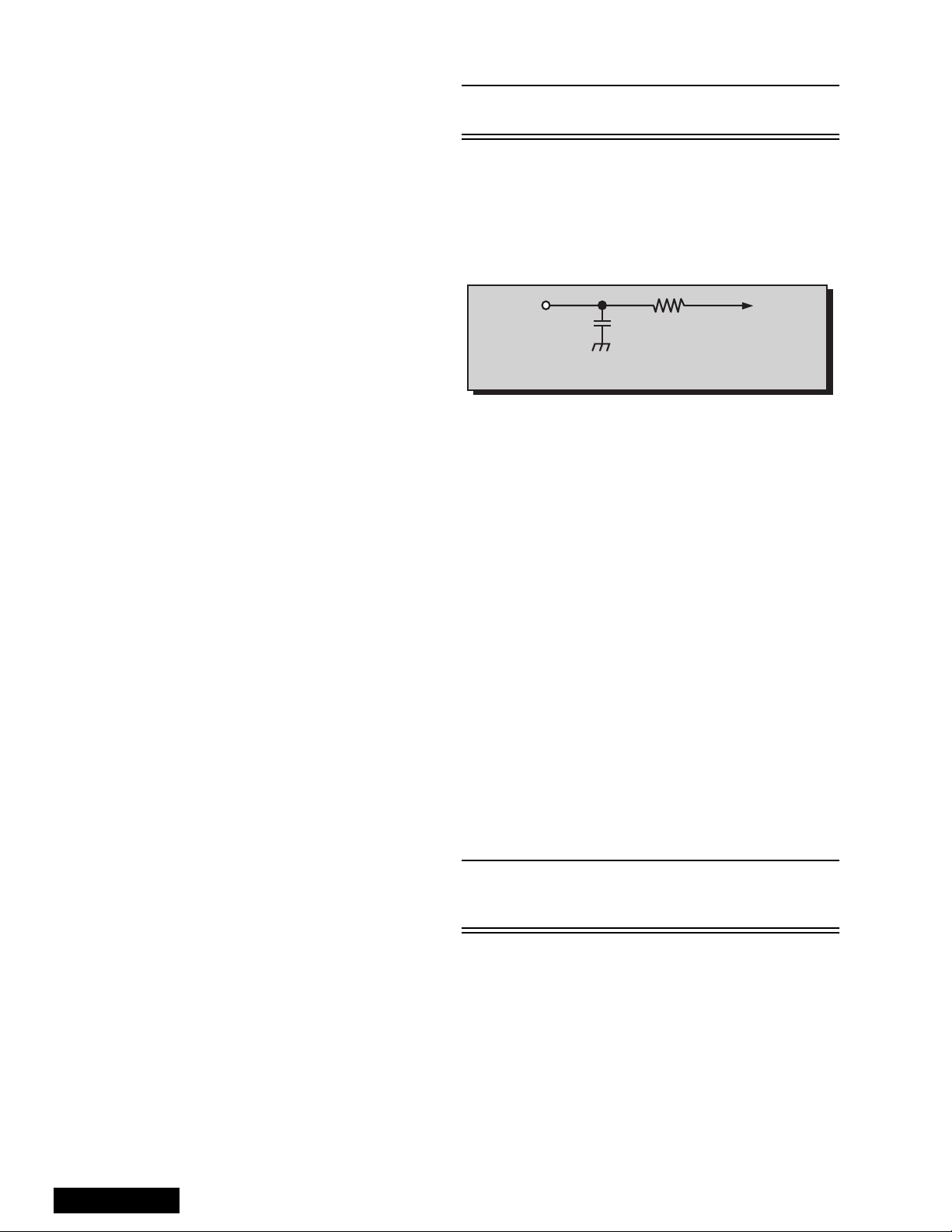
1. Connect an RMS meter (AC Range) with fil ter jig
as shown in Fig. 11.
RMS
METER
10k
TPE11
L_OUT
4700p
Figure 11. Filter Jig
2. Connect an RF signal generator to the RF
antenna input.
Procedure:
1. Apply the following signal from the RF signal
generator:
Video: 100 IRE flat field, 30% modulation.
Audio: 300Hz, 100% modulation, monaural
(70 ± 5dB/mV, 75Ω OPEN, P/S 10dB). Make sure
to turn off 75ms pre-emphasis.
2. Adjust (S6)
measured is 106mV ± 6.0mV rms.
MTS-INPUT
data until the voltage
Stereo Separation Adjustment (S07 & S08)
Preparation:
1. Connect an RF signal generator to the RF
antenna input.
2. Connect an oscilloscope probe to TPE10 (R_out).
Procedure:
1. Set PTV to Stereo Mode (in the Audio Menu).
2. Apply the following signal from the RF signal
generator:
Video: 100 IRE flat field, 30% modulation.
Audio: 300Hz, 30% modulation, stereo (left only)
(70 ± 5dB/mV, 75Ω OPEN, P/S 10dB).
Note: Set the 30% modulation with the pilot ligh t SW
and N.R. switches “OFF” then turn the m “ON”
while testing.
3. Adjust MTS Low-Level Separation (S07) data (in
the Service Adjus tment Menu) until the amplitude
of the measured waveform on the scope is
minimum.
4. Apply the following signal from the RF
signal generator:
Video: 100 IRE flat field, 30% modulation. Audio:
3KHz, 30% modulation, stereo (left only).
(70 ± 5dB/mV, 75Ω OPEN, P/S 10dB) .
Service Manual
- 14 -
 Loading...