

Panasonic PT-50LCZ70, PT-56LCZ70, PT-61LCZ70, PT-50LCZ7, PT-56LCZ7 Service Manual
...
Multi Media Display
PT-50LCZ70
PT-56LCZ70
PT-61LCZ70
PT-50LCZ7
PT-56LCZ7
PT-61LCZ7
PT-50LCZ70-K
ORDER NO. MKE0706852CE
B2
PT-56LCZ70-K
PT-61LCZ70-K
Vol. 1
© 2007 Panasonic Shikoku Electronics Co., Ltd. All
rights reserved. Unauthorized copying and
distribution is a violation of law.
PT-50LCZ70 / PT-56LCZ70 / PT-61LCZ70 / PT-50LCZ7 / PT-56LCZ7 / PT-61LCZ7
CONTENTS
Page Page
1 Safety Precautions 3
1.1. General Guidelines
1.2. Leakage Current Cold Check
1.3. Leakage Current Hot Check
1.4. Disposal Lamp
2 Warning
2.1. Prevention of Electro Static Discharge (ESD) to
Electrostatically Sensitive (ES) Devices
3 Service Navigation
3.1. Introduction
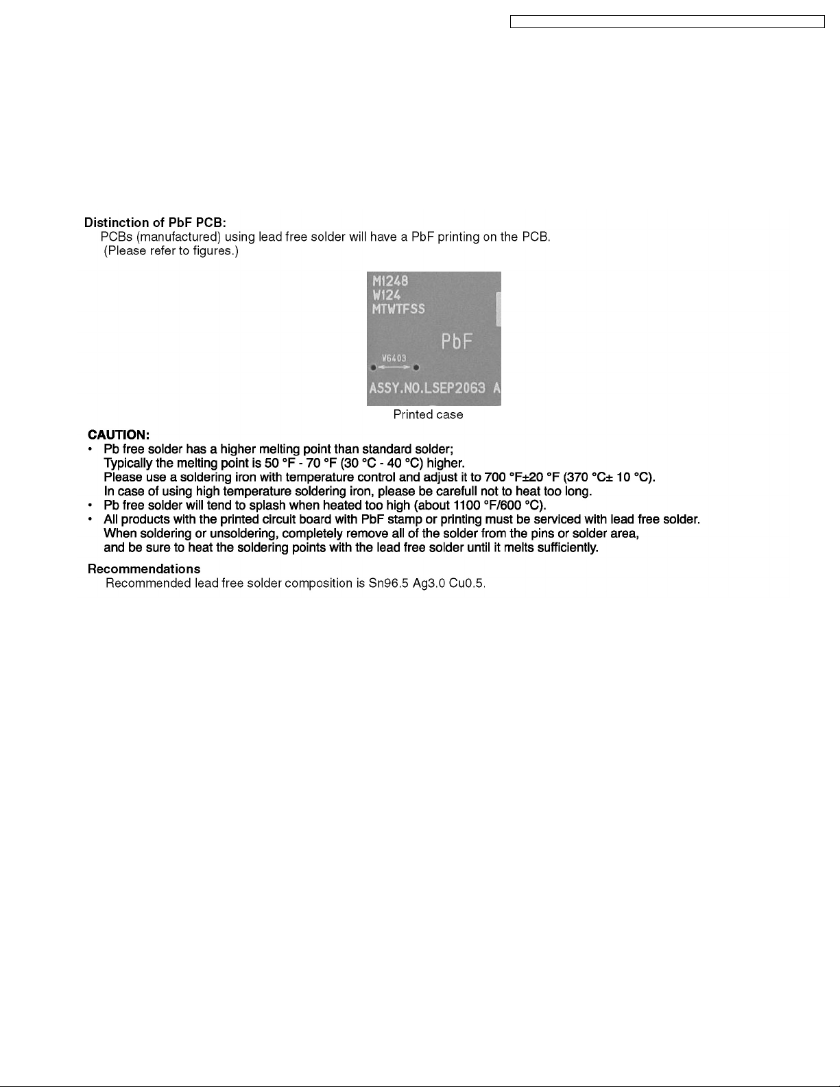
3.2. About Lead Free Solder (PbF)
4 Specifications
5 Service Mode
6 Troubleshooting Guide
6.1. Troubleshooting Hints for Block Level Repair
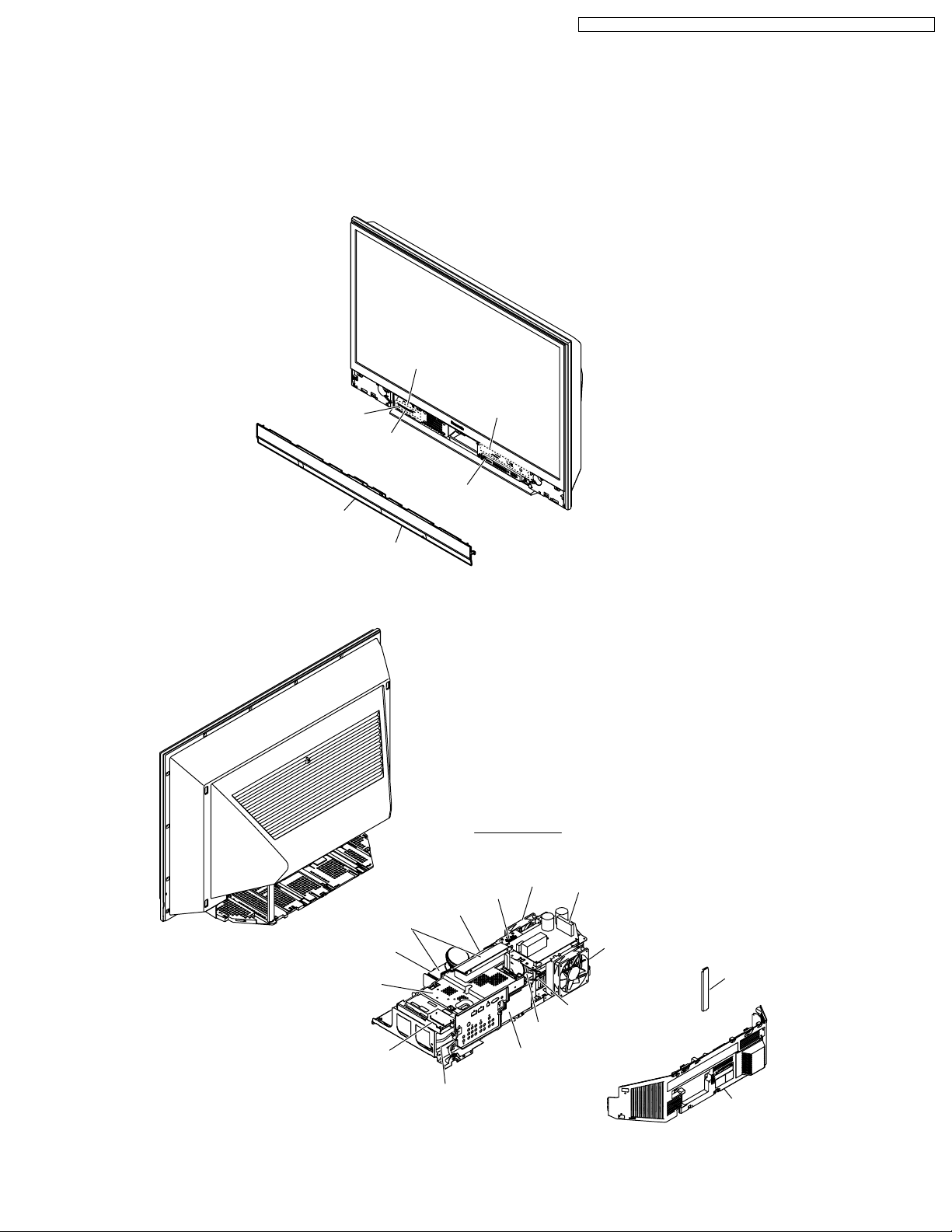
7 Disassembly and Assembly Instructions
7.1. Cabinet Section
8 Measurements and Adjustments
8.1. Adjustment Procedures 1
9 Maintenance
9.1. Cleaning Methods
10 Voltage Chart and Waveform of Connectors
11 Block Diagrams
12 Schematic Diagrams
12.1. SCHEMATIC DIAGRAM & CIRCUIT BOARD LAYOUT
NOTES
19
19
33
33
55
55
58
58
59
63
65
65
3
3
3
3
4
4
5
5
5
6
7
12.2. INTERCONNECTION SCHEMATIC DIAGRAM
12.3. POWER SCHEMATIC DIAGRAMS
12.4. SD/HDMI SCHEMATIC DIAGRAM
12.5. REAR JACK SCHEMATIC DIAGRAM
12.6. FRONT JACK/OPERATION / POWER SWITCH / TUNER
SCHEMATIC DIAGRAM
13 Printed Circuit Board
13.1. POWER P.C.B.
13.2. SD/HDMI P.C.B.
13.3. REAR JACK P.C.B.
13.4. FRONT JACK/OPERATION P.C.B. / TUNER P.C.B. /
POWER SWITCH/OPERATION P.C.B.
14 Ex ploded Vie w s
14.1. MAIN PARTS SECTION
14.2. BASE BODY SECTION
14.3. DISPLAY SECTION
14.4. SCREEN SECTION
14.5. OPT/TV UNIT SECTION
14.6. LAMP UNIT SECTION
14.7. PACKING PARTS AND ACCESSORIES SECTION
15 Replacement Parts List
15.1. REPLACEMENT NOTES
15.2. MECHANICAL REPLACEMENT PARTS LIST
15.3. ELECTRICAL REPLACEMENT PARTS LIST
66
67
68
69
74
75
75
76
77
78
79
79
81
82
84
86
87
88
89
89
90
91
2
1 Safety Precautions
1.1. General Guidelines
1. For continued safety, no modification of any circuit should
be attempted.
2. Disconnect AC Plug before disassembling this unit.
3. It is advisable to use an isolation transformer in the AC
supply before servicing.
4. When servicing, observe the original lead dress. If a short
circuit is found, replace all parts which have been
overheated or damaged by the short circuit.
5. After servicing, see to it that all the protective devices such
as insulation barriers, insulation papers, shield, and
isolation R-C combinations etc. are properly installed.
6. After servicing, be sure to restore the wires, leads,
insulation barriers, shields, etc.
7. After servicing, make the leakage current checks to prevent
the customer from being exposed to shock hazards.
Caution:
Use a separate Isolation Transformer for this unit when
servicing.
PT-50LCZ70 / PT-56LCZ70 / PT-61LCZ70 / PT-50LCZ7 / PT-56LCZ7 / PT-61LCZ7
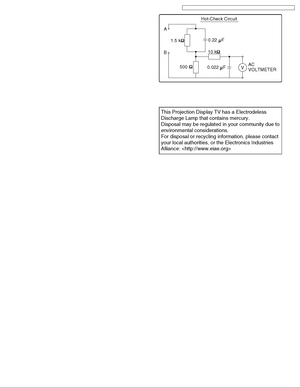
Figure 1
1.4. Disposal Lamp
1.2. Leakage Current Cold Check
1. Unplug the AC cord and connect a jumper between the two
prongs on the plug.
2. For physically operated power switches, turn power on.
Otherwise skip step 2.
3. Measure the resistance value, with an ohmmeter, between
the jumpered AC plug and each exposed metallic cabinet
part on the receiver, such as screwheads, connectors, etc.
When the exposed metallic part has a return path to the
chassis, the reading should be between 1 MΩ and 12 MΩ.
When the exposed metal does not have a return path to the
chassis, the reading must be infinity.
1.3. Leakage Current Hot Check
1. Plug the AC cord directly into the AC outlet.
Do not use an isolation transformer for this check.
2. Connect "A" to exposed metallic part on the set. And
connect "B" to a good earth ground, as shown in Figure 1.
3. Use an AC voltmeter, with 1 kΩ/V or more sensitivity, to
measure the potential across the resistor.
4. Check each exposed metallic part, and measure the
voltage at each point.
5. Reverse the AC plug in the AC outlet and repeat each of the
above measurements.
6. The potential at any point should not exceed 0.25 V RMS.
A leakage current tester (Simpson Model 228 equivalent)
may be used to make the hot checks. Leakage current must
not exceed 1/2 mA. In case a measurement is outside of
the limits specified, there is a possibility of shock hazard,
and the receiver should be repaired and rechecked before
it is returned to the custom er.
3

PT-50LCZ70 / PT-56LCZ70 / PT-61LCZ70 / PT-50LCZ7 / PT-56LCZ7 / PT-61LCZ7
2 Warning
2.1. Prevention of Electro Static Discharge (ESD) to Electrostatically Sensitive (ES) Devices
Some semiconductor (solid state) devices can be damaged easily by static electricity. Such components commonly are called
Electrostatically Sensitive (ES) Devices. Examples of typical ES devices are integrated circuits and some field-effect transistors and
semiconductor "chip" components. The following techniques should be used to help reduce the incidence of component damage
caused by electro static discharge (ESD).
1. Immediately before handling any semiconductor component or semiconductor-equipped assembly, drain off any ESD on your
body by touching a known earth ground. Alternatively, obtain and wear a commercially available discharging ESD wrist strap,
which should be removed for potential shock reasons prior to applying power to the unit under test.
2. After removing an electrical assembly equipped with ES devices, place the assembly on a conductive surface such as
aluminum foil, to prevent electrostatic charge buildup or exposure of the assembly.
3. Use only a grounded-tip soldering iron to solder or unsolder ES devices.
4. Use only an antistatic solder removal device. Some solder removal devices not classified as "antistatic (ESD protected)" can
generate electrical charge sufficient to damage ES devices.
5. Do not use freon-propelled chemicals. These can generate electrical charges sufficient to damage ES devices.
6. Do not remove a replacement ES device from its protective package until immediately before you are ready to install it. (Most
replacement ES devices are packaged with leads electrically shorted together by conductive foam, aluminum foil or comparable
conductive material).
7. Immediately before removing the protective material from the leads of a replacement ES device, touch the protective material
to the chassis or circuit assembly into which the device will be installed.
CAUTION :
Be sure no power is applied to the chassis or circuit, and observe all other safety precautions.
8. Minimize bodily motions when handling unpackaged replacement ES devices. (Otherwise harmless motion such as the
brushing together of your clothes fabric or the lifting of your foot from a carpeted floor can generate static electricity (ESD)
sufficient to damage an ES device).
4
PT-50LCZ70 / PT-56LCZ70 / PT-61LCZ70 / PT-50LCZ7 / PT-56LCZ7 / PT-61LCZ7
3 Service Navigation
3.1. Introduction
This service manual contains technical information which will allow service personnel´s to understand and service this model.
Please place orders using the parts list and not the drawing reference numbers.
If the circuit is changed or modified, this information will be followed by supplement service manual to be filed with original service
manual.
3.2. About Lead Free Solder (PbF)
5
PT-50LCZ70 / PT-56LCZ70 / PT-61LCZ70 / PT-50LCZ7 / PT-56LCZ7 / PT-61LCZ7
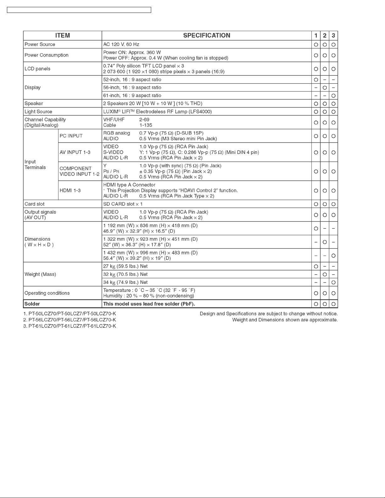
4 Specifications
6
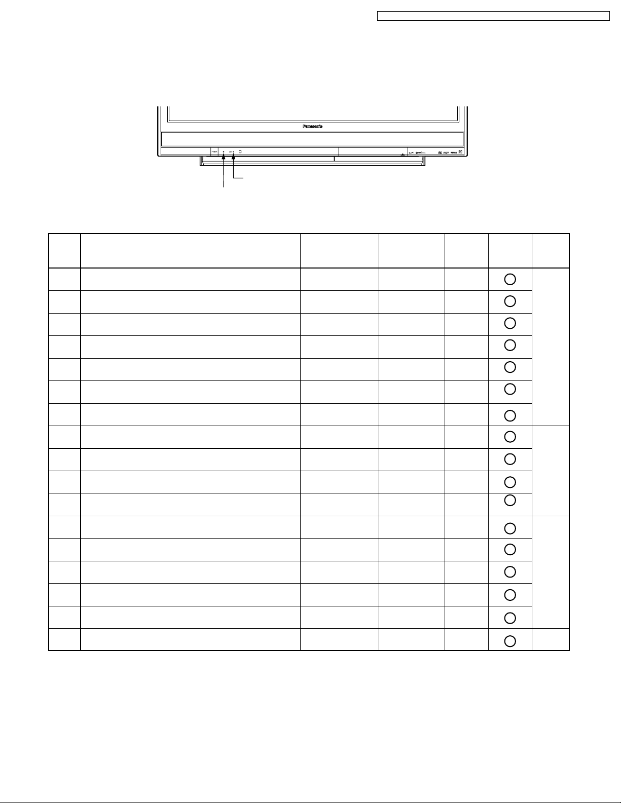
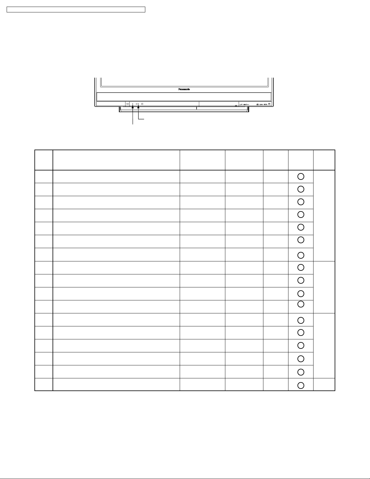
5 Service Mode
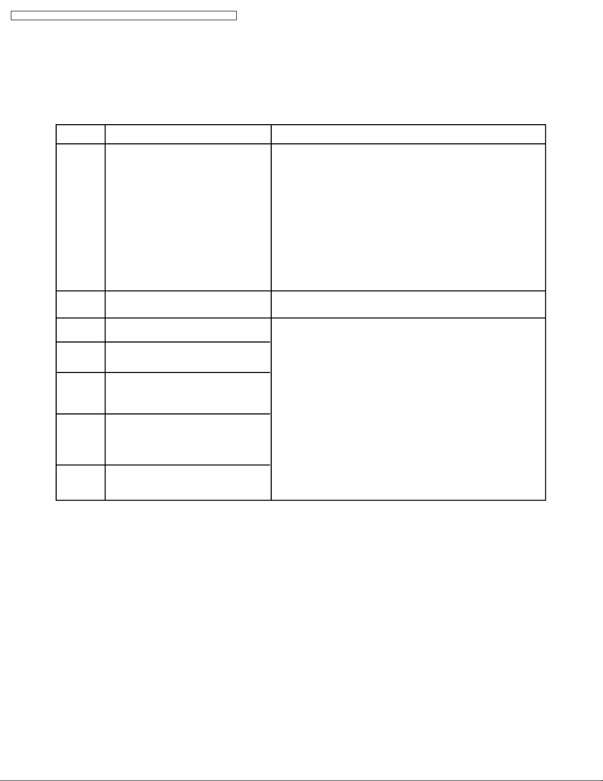
INDICATIONS FOR ERROR CONDITIONS
Each Indicator facilitates finding the cause of an error.
When an error is detected, the Lamp goes off and the indicators on the front flash.
LAMP Indicator
POWER Indicator
PT-50LCZ70 / PT-56LCZ70 / PT-61LCZ70 / PT-50LCZ7 / PT-56LCZ7 / PT-61LCZ7
(Note 1)
Priority
1
Over voltage/Over current (SOS)
2
Abnormal voltage (DTV+9V line)
Abnormal voltage (SUB+5V line)
3
4
Abnormal voltage (MAIN+3.3V line)
5
IC4501 (Audio Amp) failure
Communication error between Peaks (IC8001)
6
and TV Microcontroller (IC6004)
Communication error between Peaks (IC8001)
7
and TV Microcontroller (IC6004)
12
Lamp does not light up
9
Lamp failure
10
Abnormal Lamp temperature
11
Lamp communication error
14
Lamp Fan stops
Error Information
POWER Indicator
flashes orange
1
2
3
4
6
7
9
-
-
-
-
-
LAMP Indicator
flashes red
-
-
-
-
-
-
-
2
3
4
5
8
SOS
01
02
03
04
06
07
09
02
03
04
05
08
LAMP OFF
RESET
AC
ON/OFF
Power
ON/OFF
(Note 2)
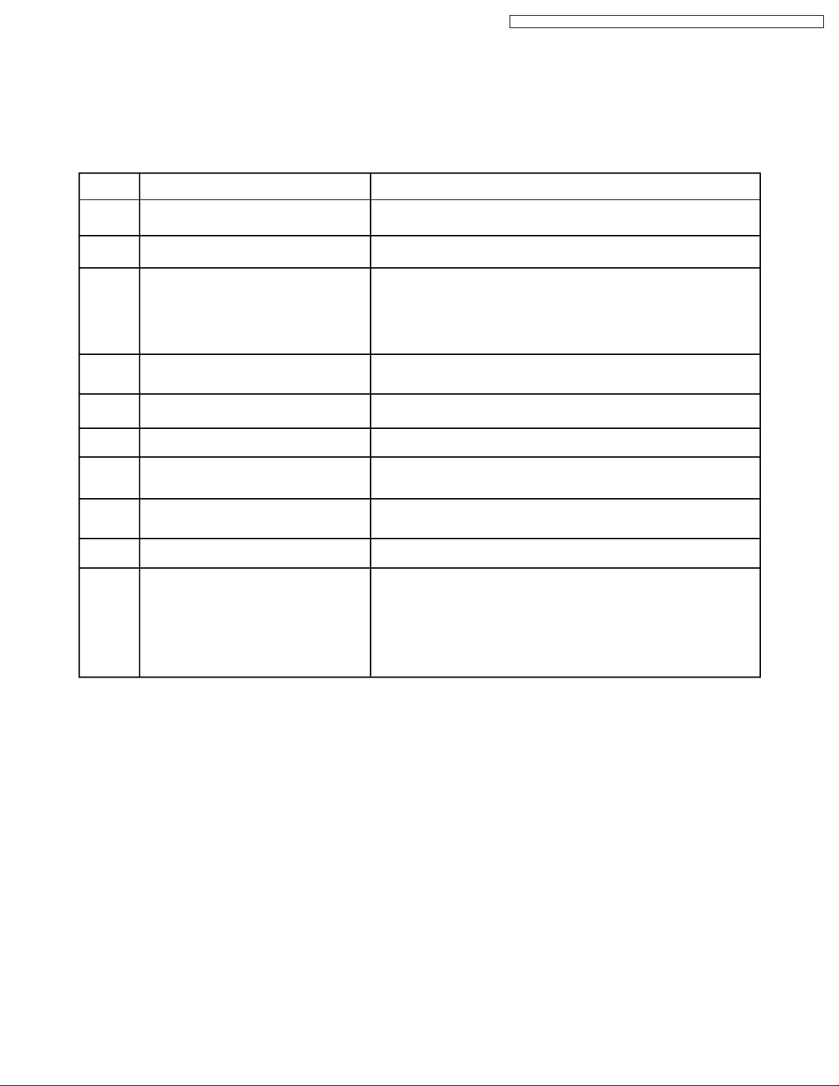
15
Fan Case Unit (OPT Fan) stops
16
Front Fan or Rear Fan stops
17
Rear Fan or Front Fan stops
13
Rear Jack PCB connection error
8
Abnormal Lamp input voltage (+26V)
Note:
1. The detected Error data will be stored in the EEPROM, and SOS History (Code) is displayed in Self Check mode
or Service Adjust mode (SRV-TOOL).
2. The Lamp Indicator will flash X5 immediately after the Lamp goes off. For this SOS only, the TV power will remain on.
-
-
-
-
-
7
9
10
11
12
13
09
0A
0B
0C
0D
AC
ON/OFF
Power
ON/OFF
PT-50LCZ70 / PT-56LCZ70 / PT-61LCZ70 / PT-50LCZ7 / PT-56LCZ7 / PT-61LCZ7
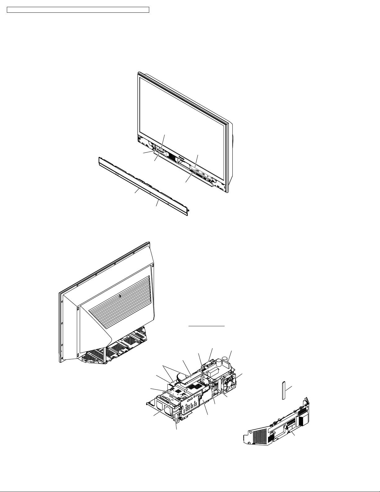
MAIN PARTS LOCATION
POWER LED
LAMP LED
Front Cover Unit
<Front View>
Power Switch
/Operation P.C.B.
Front Jack
/Operation P.C.B.
SD/HDMI P.C.B.
Front Door
Air Filters
Fan Case Unit
(OPT Fan)
Main P.C.B./
Drive P.C.B.
<Rear View>
Lamp Fan
Top Duct Unit
OPT/TV Unit
Front Fan
Lamp Unit
RF AMP
Power Supply P.C.B.
Rear Fan
Support
Shield
Thermal Fuse
Tuner P.C.B.
Rear Jack P.C.B.
Power P.C.B.
Rear Cover
8
PT-50LCZ70 / PT-56LCZ70 / PT-61LCZ70 / PT-50LCZ7 / PT-56LCZ7 / PT-61LCZ7
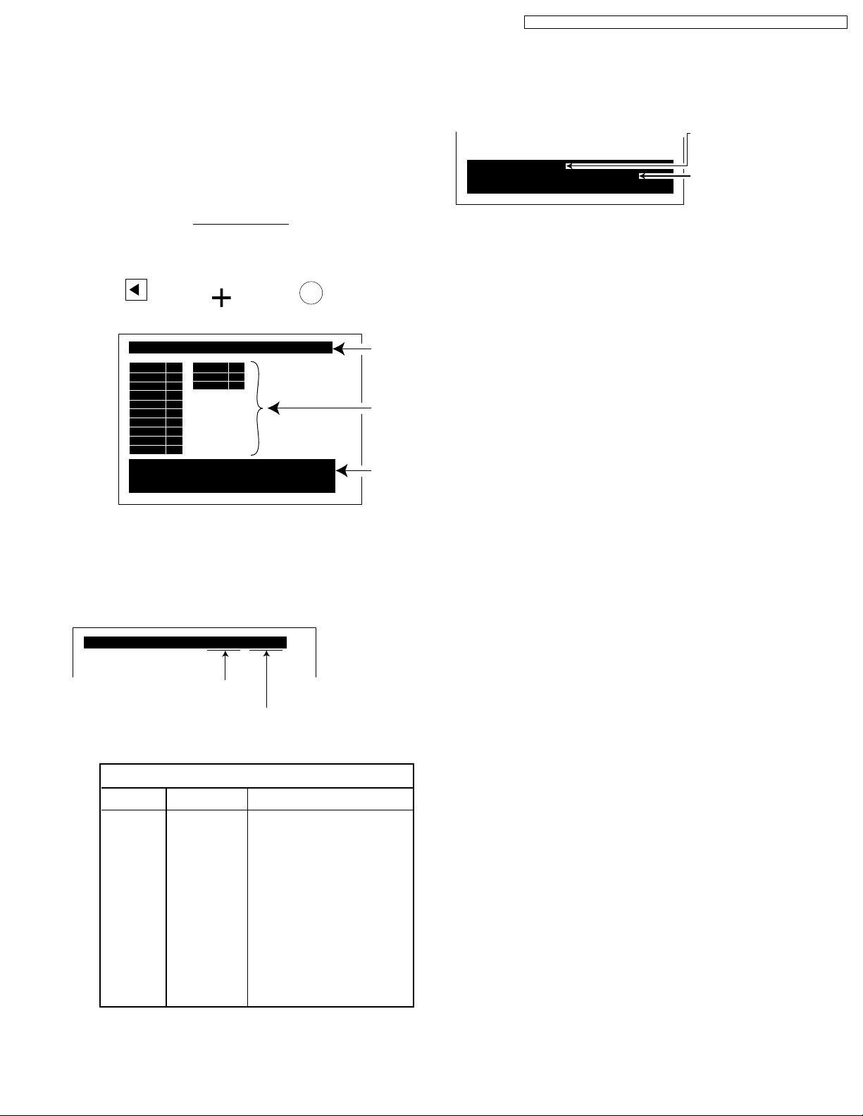
SELF CHECK
In this mode, the following information can be confirmed on the
screen:
- Peaks software version and EEPROM data version
- Communication check between Peaks IC and each ICs
- SOS History
Self Check
Enter:
VOLUME DOWN button + OK key
(for more than 3 seconds in power on condition)
_
VOL
(on the front)
SELF CHECK 0.480-00.16
DT
ADV
VSW
ADAV
ASW
TUN1
TUN2
FE
GenX4
MEM1
SOS POWER: 02 04
SOS LAMP : 08 09 0A 0B
Copyright 2007 Matsushita Electric Industrial Co., Ltd.
MEM2 OK
OK
GC5P OK
OK
FPGA OK
OK
OK
OK
OK
OK
OK
OK
OK
OK
(on the remote)
*1
*2
*3
*3. SOS History
SOS History
The number of time
Power Indicator flashed
: 01 ~ 09
SOS POWER: 02 04
SOS LAMP : 08 09 0A 0B
Copyright 2007 Matsushita Electric Industrial Co., Ltd.
The number of time
Lamp Indicator flashed
: 02 ~ 0D
Note:
If the same SOS error occurs more than once, only one
code will be displayed.
<Self Check>
Exit:
Unplug the AC cord.
Fig. 1-1
*1. Peaks software version and Peaks EEPROM data version
SELF CHECK 0.480-00.16
Peaks software version
Peaks EEPROM data version
*2. Communication check results (OK or NG) between Peaks
IC8001 and each of the following ICs.
(Communication check for I2C bus)
Display Item
DT
ADV
VSW
ADAV
ASW
TUN1
TUN2
FE
GenX 4
MEM1
MEM2
GC5P
FPGA
ICs Description
IC8001
IC5510
IC3001
IC4001
IC4101
TU8201
TU8201
IC8802
IC6004
IC6005
IC8201
IC7101
IC7119
PEAKS internal check
AD/HDMI Interface
Video SW
Audio DSP
Audio SW
Tuner PLL block
Tuner MTS block
Demodulator
TV Microcontroller
GenX4 EEPROM
Peaks EEPROM
GC
FPGA
9
PT-50LCZ70 / PT-56LCZ70 / PT-61LCZ70 / PT-50LCZ7 / PT-56LCZ7 / PT-61LCZ7
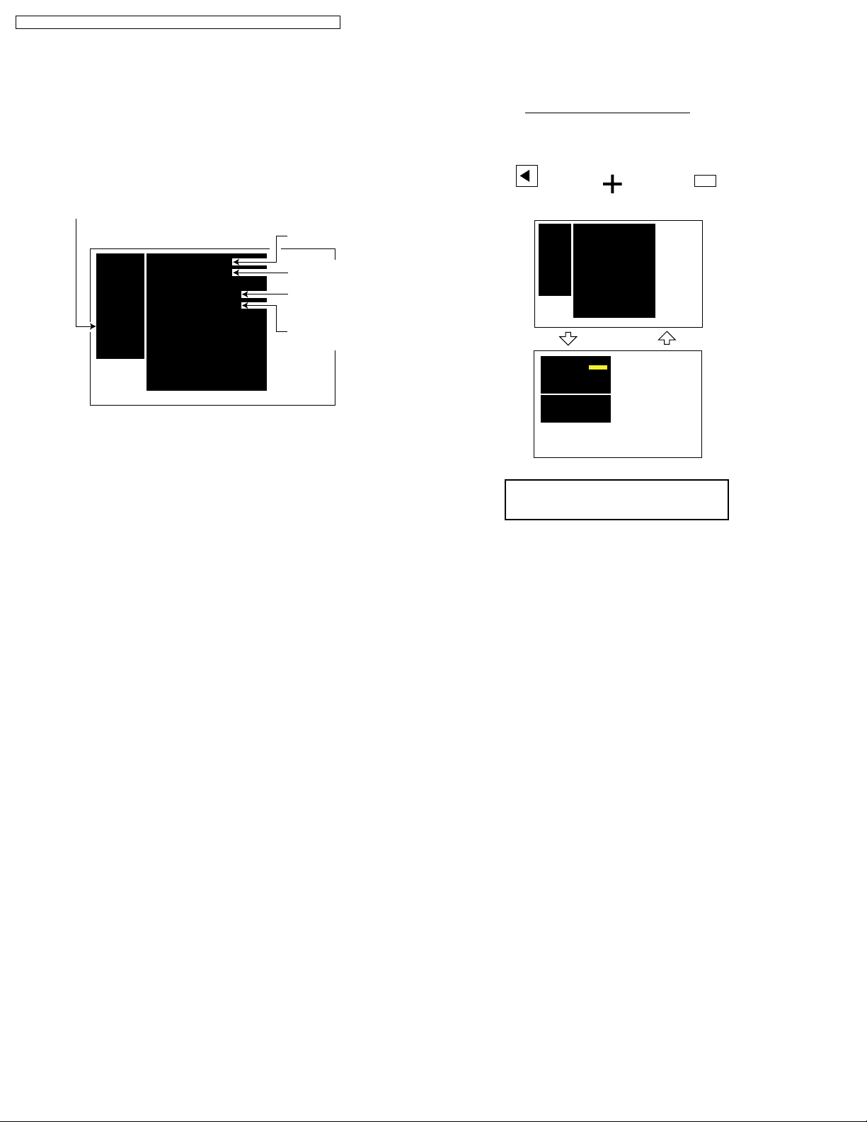
SERVICE ADJUST MODE
In this mode, the following information can be confirmed on the
screen:
MMD-CHK
- Focus, Tilt, H/V Picture Position adjustment
- Internal pattern for LCD-CHK, GC-CHK
Peaks software
version
SRVICE
ADJUST
WB-ADJ
OPTION
RM-SET
SRV-TOOL
MMD-CHK
Peaks SOFT
Peaks EEP
LSI DATA
GenX SOFT
GenX EEP
GenX ROMCOR
GC5P EEP
FPGA
FACTDATA
<Main Menu>
0.480
0.16
0.00.5b
0.15.60
0.00.00
0.00.00
20
0.3a
12FF-FFFF
Peaks EEPROM
data version
TV Microcontroller
software version
TV Microcontroller
EEPROM data version
Service Adjust Mode
Enter:
VOLUME DOWN button + RECALL key (3 times)
(in power on condition)
RECALL (X3)
_
VOL
(on the front)
SRVICE
Peaks SOFT
ADJUST
WB-ADJ
OPTION
RM-SET
SRV-TOOL
MMD-CHK
MMD-CHK
FREQ
1,2:MAIN SELECT
3,4:SUB SELECT
9 :PICTURE MENU SELECT
VOL:ADJUST
0.480
Peaks EEP
0.16
LSI DATA
0.00.5b
GenX SOFT
0.15.60
GenX EEP
0.00.00
GenX ROMCOR
0.00.00
GC5P EEP
20
FPGA
0.3a
FACTDATA
12FF-FFFF
<Main Menu>
VIVID
ON
<MMD-CHK 1/8>
CAUTION:
Do not change any parameters!
(on the remote)
1 key2 key
Exit from Main Menu:
Power OFF.
Fig. 2-1
10
PT-50LCZ70 / PT-56LCZ70 / PT-61LCZ70 / PT-50LCZ7 / PT-56LCZ7 / PT-61LCZ7
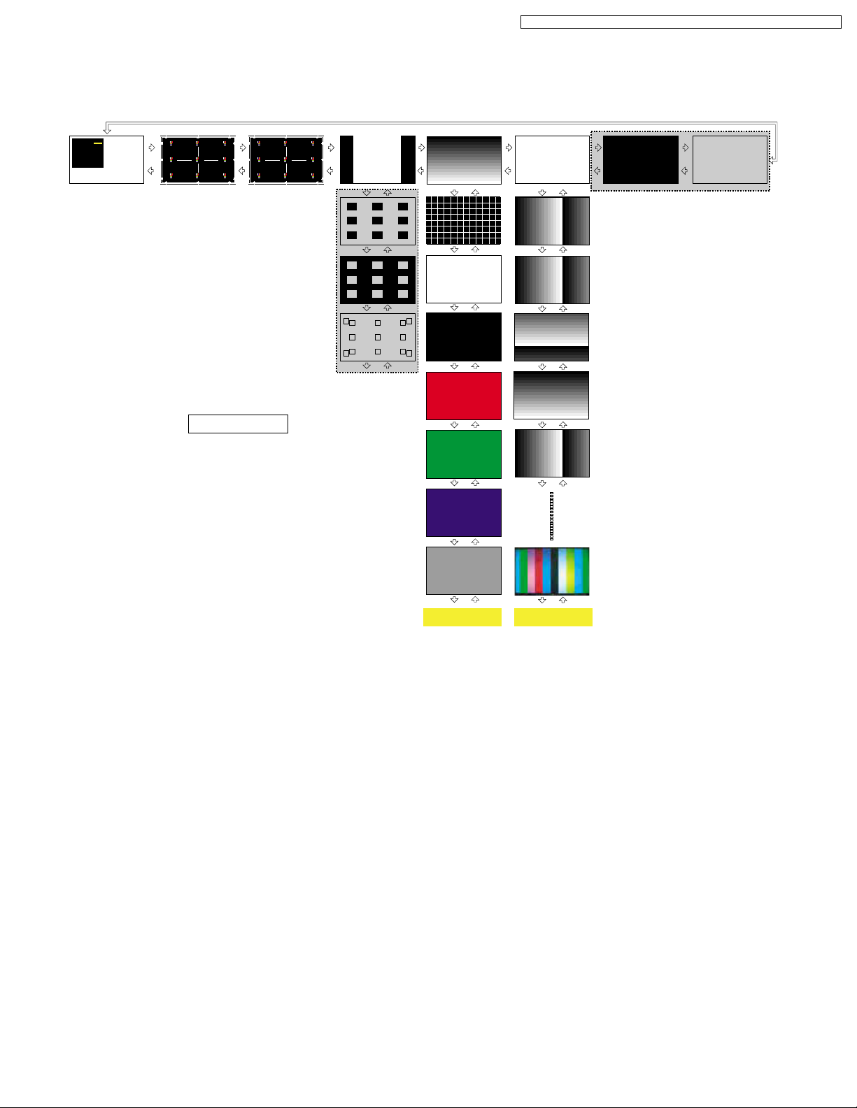
MMD-CHK 1/8~8/8 and internal pattern
Perform the Picture Position adjustment by pressing VOL+/- key, and display the internal pattern for LCD-CHK, GC-CHK.
3 key
MMD-CHK
VIVID
FREQ
ON
1,2:MAIN SELECT
3,4:SUB SELECT
9 :PICTURE MENU SELECT
VOL:ADJUST
<MMD-CHK 1/8> <MMD-CHK 2/8> <MMD-CHK 3/8> <MMD-CHK 4/8> <MMD-CHK 5/8> <MMD-CHK 6/8> <MMD-CHK 7/8> <MMD-CHK 8/8>
3 key
OPT HPOS 0024 OPT HPOS 001F
4 key
3 key
4 key
3 key
(Not used for service)
4 key
VOL+ key VOL- key
<SRV-TOOL>
3 key
4 key
VOL+ key
VOL- key
3 key
4 key
VOL+ key VOL- key
3 key
4 key
(Not used for service)
3 key
4 key
4 key
(Not used for service)
CAUTION:
Do not change any parameters!
Note:
Press 1 key to return Main Menu.
VOL+ key VOL- key
VOL+ key VOL- key
VOL+ key VOL- key
VOL+ key VOL- key
VOL+ key VOL- key
VOL+ key VOL- key
VOL+ key VOL- key
VOL+ key VOL- key
VOL+ key VOL- key
VOL+ key VOL- key
Internal Pattern for
LCD-CHK (Figure. A)
VOL+ key VOL- key
VOL+ key VOL- key
VOL+ key VOL- key
VOL+ key VOL- key
VOL+ key VOL- key
VOL+ key VOL- key
Internal Pattern for
GC-CHK (Figure. B)
11
PT-50LCZ70 / PT-56LCZ70 / PT-61LCZ70 / PT-50LCZ7 / PT-56LCZ7 / PT-61LCZ7
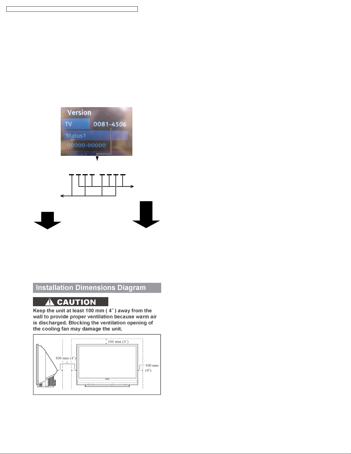
TO READ THE PEAKS SOFTWARE
VERSION AND TV MICROCONTROLLER
SOFTWARE VERSION
1. Press MENU key with the power on.
2. Press CH UP/DOWN key and select "Setup."
Then press OK key.
3. Press CH UP/DOWN key and select "About."
Then press OK key.
4. Select "Version" and press OK key.
Version menu will appear as shown below.
0081-4506
Read every
Read every
other number
from the right:
other number
from the left:
LAMP CAUTION
The Lamp Unit becomes very hot during operation. When
replacing the Lamp Unit, wait until it has cooled off (1 hour or
more).
TOP DUCT UNIT NOTE
The optical parts will be exposed to the dust in the air when the
Top Duct Unit is removed. Therefore, it is strongly recommend
to remove the Top Duct Unit only in a clean room.
Peaks software
Ver. : 0.480
TV Microcontroller
software Ver. : 0.156
INSTALLATION DIMENSIONS DIAGRAM
12
MODEL
PT-50LCZ70
PT-56LCZ70
PT-61LCZ70
PT-50LCZ7
PT-56LCZ7
PT-61LCZ7
PT-50LCZ70-K
PT-56LCZ70-K
PT-61LCZ70-K
NOT USED
MARK
A
B
C
D
E
F
G
H
I
PT
Note:
Refer to Item 3 of Schematic Diagram Notes of
Schematic Diagram and Circuit Board Layout Notes,
for mark "PT."
PT-50LCZ70 / PT-56LCZ70 / PT-61LCZ70 / PT-50LCZ7 / PT-56LCZ7 / PT-61LCZ7
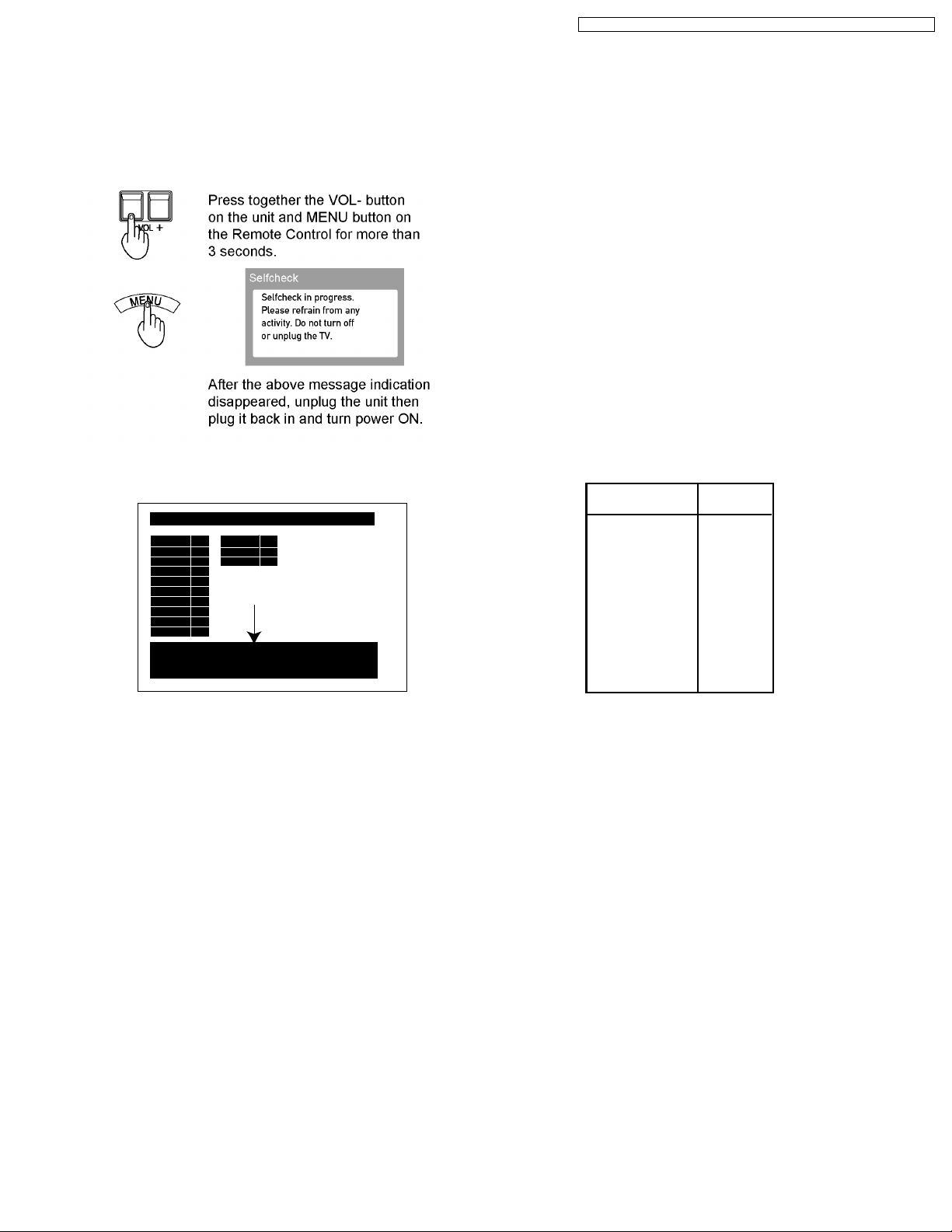
RESET USER’S MEMORY FUNCTIONS
Use when moving unit to a new location, or when First
Time Setup needs to be done over, or if the password
for V-chip has been forgotten.
Note:
SOS History will be cleared after it is displayed.
SELF CHECK 0.480-00.16
DT
ADV
VSW
ADAV
ASW
TUN1
TUN2
FE
GenX4
MEM1
SOS POWER: 02 04
SOS LAMP : 08 09 0A 0B
Copyright 2007 Matsushita Electric Industrial Co., Ltd.
MEM2 OK
OK
OK
GC5P OK
OK
FPGA OK
OK
OK
OK
OK
OK
OK
OK
SOS History
DO NOT UNPLUG AC CORD DURING
COOLING OPERATION
The lamp cooling fan will continue to operate for approximately
30 seconds after the power is turned off.
At the same time, the POWER LED will flash red.
Do not disconnect the AC Cord from the power outlet and do
not open any circuit breakers while the cooling fan is still
operating.
HOT CIRCUIT
Primary circuit exists on the Power P.C.B.
This circuit is identified as "HOT" on the P.C.B. and in the
Service Manual. Use extreme care to prevent accidental shock
when servicing.
MODEL NO. IDENTIFICATION MARK
Use Marks shown in the chart below to distinguish the different
models included in this Service Manual.
<Self Check-2>
13
PT-50LCZ70 / PT-56LCZ70 / PT-61LCZ70 / PT-50LCZ7 / PT-56LCZ7 / PT-61LCZ7
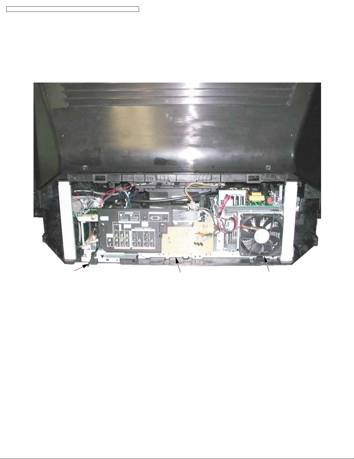
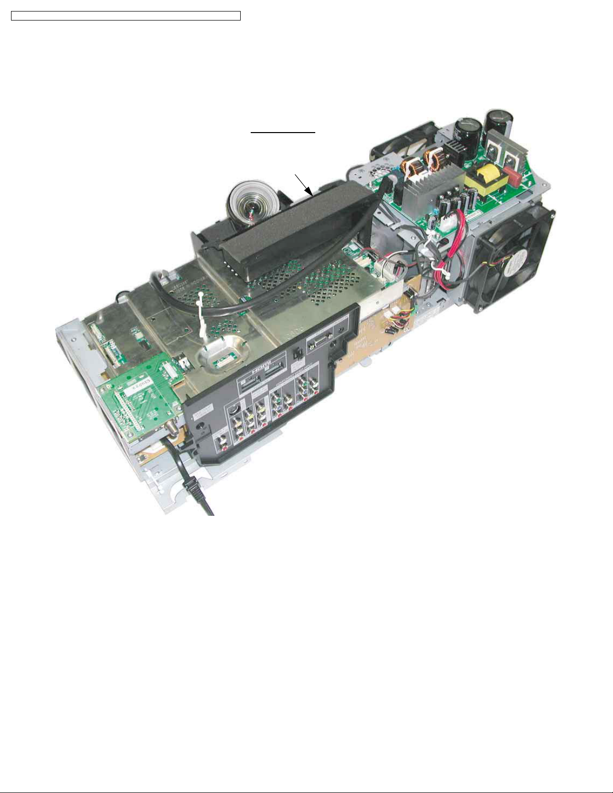
WIRE AND LEAD POSITION DIAGRAM OF THE UNIT
After servicing, make sure that all wires, leads, and clampers are placed in their original position. It is important for the best
operation of the unit.
Note: Use extreme care especially for the following.
AC Cord
OPT/TV Unit
Fig. 9-1
Rear Fan
14
PT-50LCZ70 / PT-56LCZ70 / PT-61LCZ70 / PT-50LCZ7 / PT-56LCZ7 / PT-61LCZ7
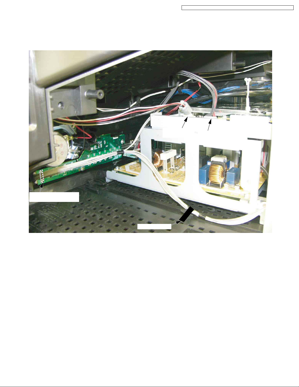
After servicing, make sure that all wires, leads, and clampers are placed in their original position. It is important for the best
operation of the unit.
Note: Use extreme care especially for the following.
CN6701
(From Rear Jack P.C.B.)
CN4501
(From Speaker)
Non Fabric Tape
Fig. 9-2
CN8201
(From SD/HDMI P.C.B.)
15
PT-50LCZ70 / PT-56LCZ70 / PT-61LCZ70 / PT-50LCZ7 / PT-56LCZ7 / PT-61LCZ7
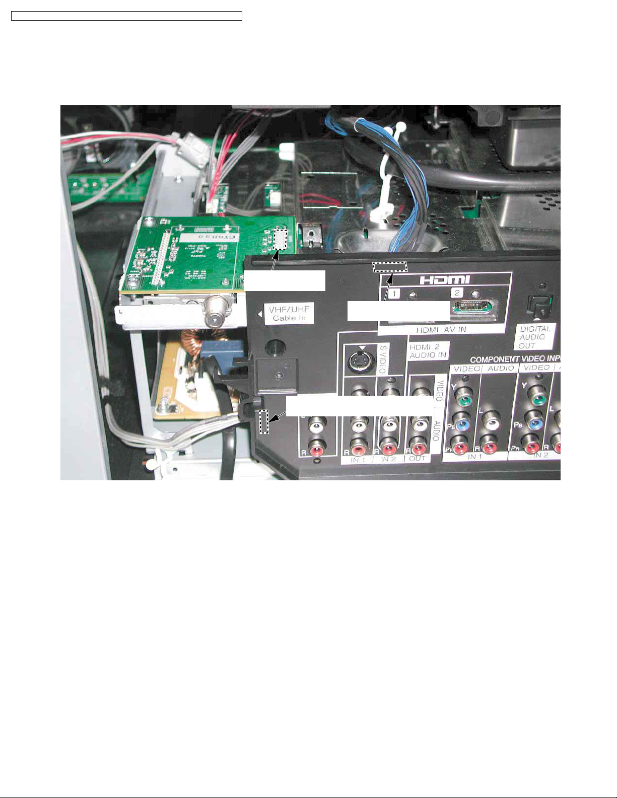
After servicing, make sure that all wires, leads, and clampers are placed in their original position. It is important for the best
operation of the unit.
Note: Use extreme care especially for the following.
CN8970
(From Main P.C.B.)
CN5503
(From SD/HDMI P.C.B.)
CN3502
(From Front Jack/Operation P.C.B.)
Fig. 9-3
16
PT-50LCZ70 / PT-56LCZ70 / PT-61LCZ70 / PT-50LCZ7 / PT-56LCZ7 / PT-61LCZ7
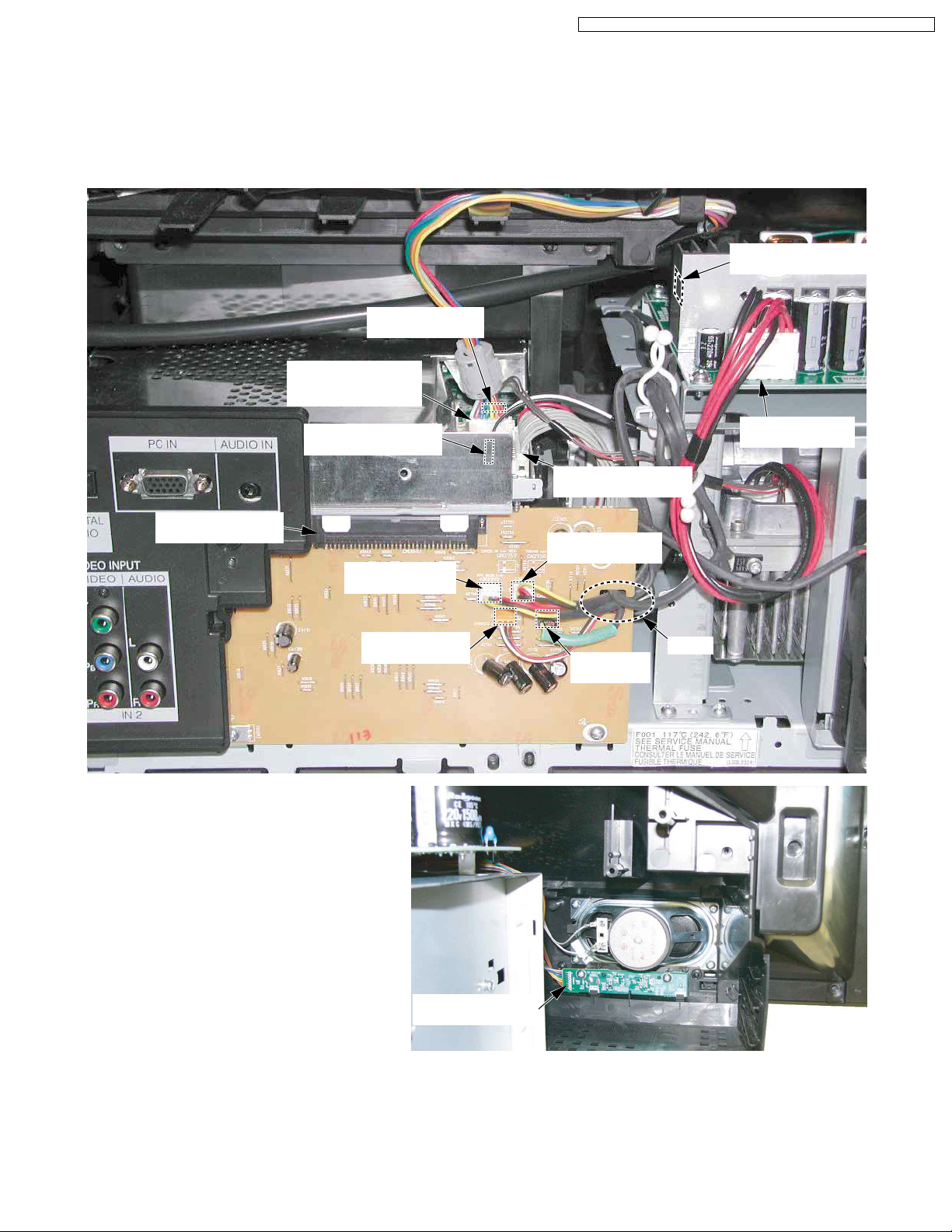
After servicing, make sure that all wires, leads, and clampers are placed in their original position. It is important for the best
operation of the unit.
Note: Use extreme care especially for the following.
CN1
(From Power P.C.B.)
CN6005
(From Lamp Unit)
CN6003
(From Power Switch
/Operation P.C.B.)
CN3501
(From Main P.C.B.)
CN1102
(From Thermal Fuse)
CN2752
(From Rear Fan)
CN2754
(From OPT Fan)
CN151
(From Lamp Unit)
CN1101
(From Power P.C.B.)
CN2751
(From Front Fan)
Clamp
CN2753
(Lamp Fan)
CN6801
(From Main P.C.B.)
Fig. 9-4
17
PT-50LCZ70 / PT-56LCZ70 / PT-61LCZ70 / PT-50LCZ7 / PT-56LCZ7 / PT-61LCZ7
After servicing, make sure that all wires, leads, and clampers are placed in their original position. It is important for the best
operation of the unit.
Note: Use extreme care especially for the following.
OPT/TV Unit
Top Duct Unit
Fig. 9-5
18
PT-50LCZ70 / PT-56LCZ70 / PT-61LCZ70 / PT-50LCZ7 / PT-56LCZ7 / PT-61LCZ7
6 Troubleshooting Guide
6.1. Troubleshooting Hints for Block Level Repair
MAIN PARTS LOCATION
<Front View>
Power Switch
/Operation P.C.B.
Front Jack
POWER LED
LAMP LED
/Operation P.C.B.
Front Cover Unit
Front Door
Fan Case Unit
(OPT Fan)
Main P.C.B./
Drive P.C.B.
Tuner P.C.B.
SD/HDMI P.C.B.
<Rear View>
Top Duct Unit
Air Filters
OPT/TV Unit
Front Fan
Lamp Fan
RF AMP
Power Supply P.C.B.
Rear Fan
Support
Shield
Thermal Fuse
Lamp Unit
Rear Jack P.C.B.
Power P.C.B.
19
Rear Cover
PT-50LCZ70 / PT-56LCZ70 / PT-61LCZ70 / PT-50LCZ7 / PT-56LCZ7 / PT-61LCZ7
INDICATIONS FOR ERROR CONDITIONS
Each Indicator facilitates finding the cause of an error.
When an error is detected, the Lamp goes off and the indicators on the front flash.
POWER Indicator
LAMP Indicator
(Note 1)
Priority
1
Over voltage/Over current (SOS)
2
Abnormal voltage (DTV+9V line)
Abnormal voltage (SUB+5V line)
3
4
Abnormal voltage (MAIN+3.3V line)
5
IC4501 (Audio Amp) failure
Communication error between Peaks (IC8001)
6
and TV Microcontroller (IC6004)
Communication error between Peaks (IC8001)
7
and TV Microcontroller (IC6004)
12
Lamp does not light up
9
Lamp failure
10
Abnormal Lamp temperature
11
Lamp communication error
14
Lamp Fan stops
15
Fan Case Unit (OPT Fan) stops
Error Information
POWER Indicator
flashes orange
1
2
3
4
6
7
9
-
-
-
-
-
-
LAMP Indicator
flashes red
-
-
-
-
-
-
-
2
3
4
5
8
9
SOS
01
02
03
04
06
07
09
02
03
04
05
08
09
LAMP OFF
RESET
AC
ON/OFF
Power
ON/OFF
(Note 2)
16
Front Fan or Rear Fan stops
17
Rear Fan or Front Fan stops
13
Rear Jack PCB connection error
8
Abnormal Lamp input voltage (+26V)
Note:
1. The detected Error data will be stored in the EEPROM, and SOS History (Code) is displayed in Self Check mode
or Service Adjust mode (SRV-TOOL).
2. The Lamp Indicator will flash X5 immediately after the Lamp goes off. For this SOS only, the TV power will remain on.
20
-
-
-
-
10
11
12
13
0A
0B
0C
0D
AC
ON/OFF
Power
ON/OFF
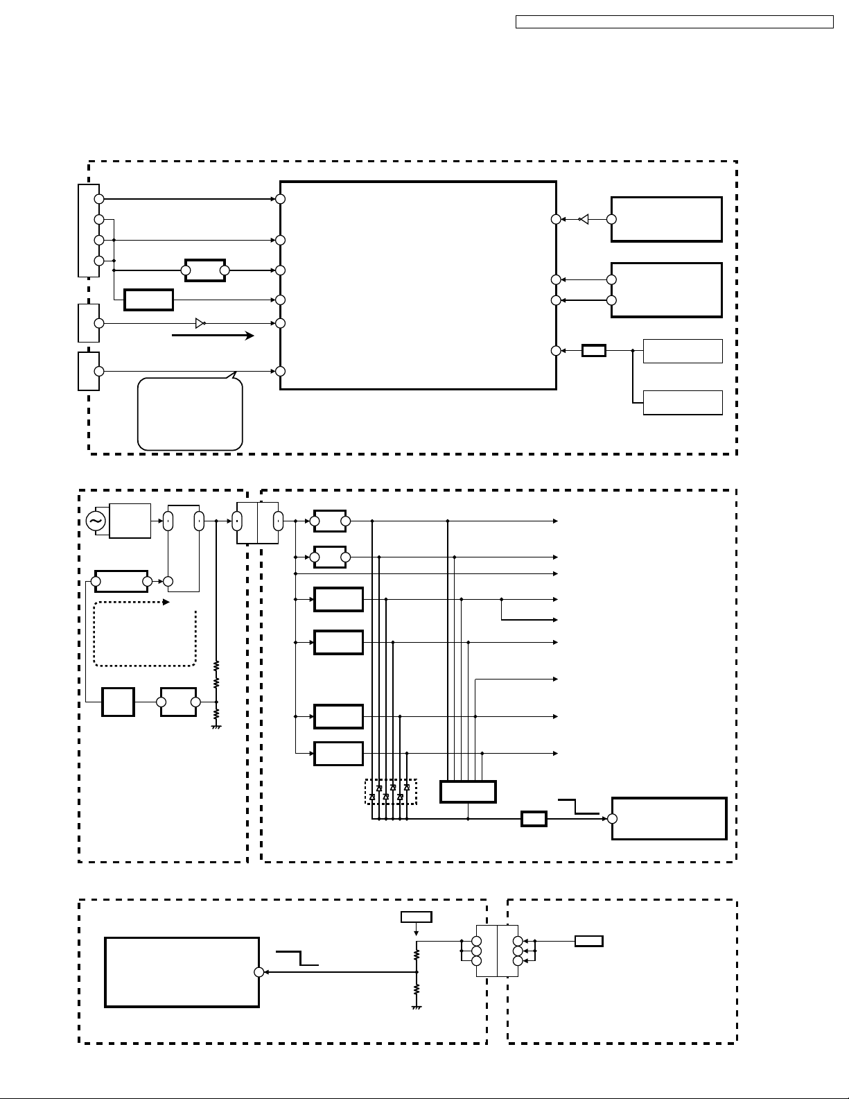
Protection Circuit
SOS terminal of IC6004 (TV microcontroller)
PT-50LCZ70 / PT-56LCZ70 / PT-61LCZ70 / PT-50LCZ7 / PT-56LCZ7 / PT-61LCZ7
IC6004 (TV MICROCONTROLLER)
126
AC STOP(L)
9
10
CN1101
11
7
CN6005
29
CN3001
IC1104,
DC-DC
CONVERTER
LAMP FAN SOS
OPT FAN SOS
FRONT FAN SOS
REAR FAN SOS
NORMAL
REAR JACK P.C.B.
CONNECTION ERROR
IC1107
Q1106
Error Information
+5V
REG.
Q6008
:APPROX. 0V
:APPROX. 0.5V
:APPROX. 1.3V
:APPROX. 2V
:APPROX. 2.8V
:APPROX. 3.3V
21
30
DTV+9V SENS (SOS(L))
34
SUB+5V SENS (SOS(L))
57
MAIN+3.3V SENS (SOS(L))
67
LAMP RXD
117
FAN SOS
[POWER Indicator one blink]
T1002
FULL-WAVE
RECTIFIER
IC1001
SWITCHING
CONTROL
(FEEDBACK LOOP)
IC1002
FEED
BACK
10
11
POWER
TRANS.
1492
IC1003
SHUNT
REG.
8
9
9
11
R1017
R1018
13
R1019
(+9V)
9
11
CN1003
CN1101
(Over voltage Detect)
SOUND SOS (H)
PANEL SOS (L)
PANEL STATUS (SOS(L))
SOS (L)
MAIN P.C.B.
Over voltage/current detection circuit
IC1107
+5V
21
REG.
IC1105
+1.8V
21
REG.
IC1104,
Q1106
DC-DC
CONVERTER
IC1103,
Q1107
DC-DC
CONVERTER
IC1202,
Q1201
DC-DC
CONVERTER
IC1201,
Q1202
DC-DC
CONVERTER
Over current
Detect
IC1101,IC1102,
IC1205
Q1102
SW
Q4502
72
48
13
114
SUB+5V
SUB+1.8V
DTV+9V
SUB+3.3V
MAIN+3.3V
SUB+1.2V
FHD+3.3V
DDR+3.3V
FHD+1.2V
Normal
IC4501
(AUDIO POWER AMP)
5
SOUND SOS (L)
IC8001 (PEAKS)
L6
PANEL SOS (L)
G1
PANEL STATUS (SOS(L))
Q1102
SW
D1104,D1105,ETC
OVER VOLT AGE
DETECT CIRCUIT
IC1101,IC1102,
IC1205
OVER CURRENT
DETECT CIRCUIT
IC6004
(TV
MICROCONTROLLER)
SOS
114
SOS (L)
POWER P.C.B. MAIN P.C.B.
[POWER Indicator two blinks]
IC6004 (TV MICROCONTROLLER)
Normal
DTV+9V SENS
30
Abnormal voltage (DTV+9V) detection circuit
DTV+9V
SOS
SOS: 0V on DTV+9V line
MAIN P.C.B. POWER P.C.B.
21
9 9
10 10
11 11
CN1101
CN1003
+9V
PT-50LCZ70 / PT-56LCZ70 / PT-61LCZ70 / PT-50LCZ7 / PT-56LCZ7 / PT-61LCZ7
[POWER Indicator three blinks]
IC6004 (TV MICROCONTROLLER)
Normal
SUB+5V SENS
34
SOS
SOS: 0V on SUB+5V line
[POWER Indicator four blinks]
IC6004 (TV MICROCONTROLLER)
Normal
MAIN+3.3V SENS
57
SOS
SOS: 0V on MAIN+3.3V line
Abnormal voltage (SUB+5V line) detection circuit
SUB+5V
IC1107
+5V
REG.
12
+9V
MAIN P.C.B.
Abnormal voltage (MAIN+3.3V line) detection circuit
MAIN+3.3V
IC1104,
DC-DC
CONVERTER
Q1106
+9V
MAIN P.C.B.
[POWER Indicator six blinks]
IC6004
(TV MICROCONTROLLER)
SOUND SOS (H)
SOS
72
Audio Amp (IC4501) failure detection circuit
Normal
SOS: Abnormal temperature for Audio amp (IC4501)
Q4502
IC4501
(AUDIO POWER AMP)
5
SOUND SOS (L)
MAIN P.C.B.
[POWER Indicator seven blinks]
Communication error between Peaks (IC8001) and TV microcontroller (IC6004) detection circuit
IC6004
(TV MICROCONTROLLER)
PANEL SOS (L)
Normal
SOS
48
IC8001 (PEAKS)
L6
PANEL SOS (L)
MAIN P.C.B.
22
PT-50LCZ70 / PT-56LCZ70 / PT-61LCZ70 / PT-50LCZ7 / PT-56LCZ7 / PT-61LCZ7
[POWER Indicator nine blinks]
Communication error between Peaks (IC8001) and TV microcontroller (IC6004) detection circuit
IC6004
(TV MICROCONTROLLER)
PANEL STATUS (SOS (L))
Normal
SOS
13
IC8001 (PEAKS)
G1
PANEL STATUS (SOS (L))
MAIN P.C.B.
[POWER Indicator ten blinks]
Abnormal voltage (LCD+17V line) detection circuit
LCD+17 V
IC6004 (TV MICROCONTROLLER)
Normal
LCD+17V SENS
10
SOS
SOS: 0V on LCD+17V line
MAIN P.C.B. POWER P.C.B.
[LAMP Indicator two blinks]
Lamp does not light up detection circuit
[LAMP Indicator three blinks]
Lamp failure detection circuit
[LAMP Indicator four blinks]
Abnormal Lamp temperature detection circuit
[LAMP Indicator five blinks]
Lamp communication error detection circuit
[LAMP Indicator thirteen blinks]
Abnormal Lamp input voltage (+26V) detection circuit
IC6004 (TV MICROCONTROLLER)
LAMP ON (H)
LAMP TXD
LAMP RXD
88
66
67
Q6008
SOS Information
Q6017
SUB+5 V
Q6005
Q6018
9 9
CN1101
2
1
7
3
CN1003
CN6005
+17V
LAMP ON (H)
LAMP TXD
LAMP RXD
SUB+5V
AC IN
F801
8A/125V
+12V
RL802
AC LINE
FILTER
POWER P.C.B.
MAIN P.C.B.
Q806
TV SUB ON (H)
AC LINE
FILTER
1
2
CN851
AC IN
CN1
AC IN
RF AMP POWER
SUPPLY P.C.B.
23
+26V
GND
CN151
TEMPERATURE
SENSOR
+26V
GND
LAMP UNIT
PT-50LCZ70 / PT-56LCZ70 / PT-61LCZ70 / PT-50LCZ7 / PT-56LCZ7 / PT-61LCZ7
[LAMP Indicator eight blinks]
[LAMP Indicator nine blinks]
[LAMP Indicator ten blinks]
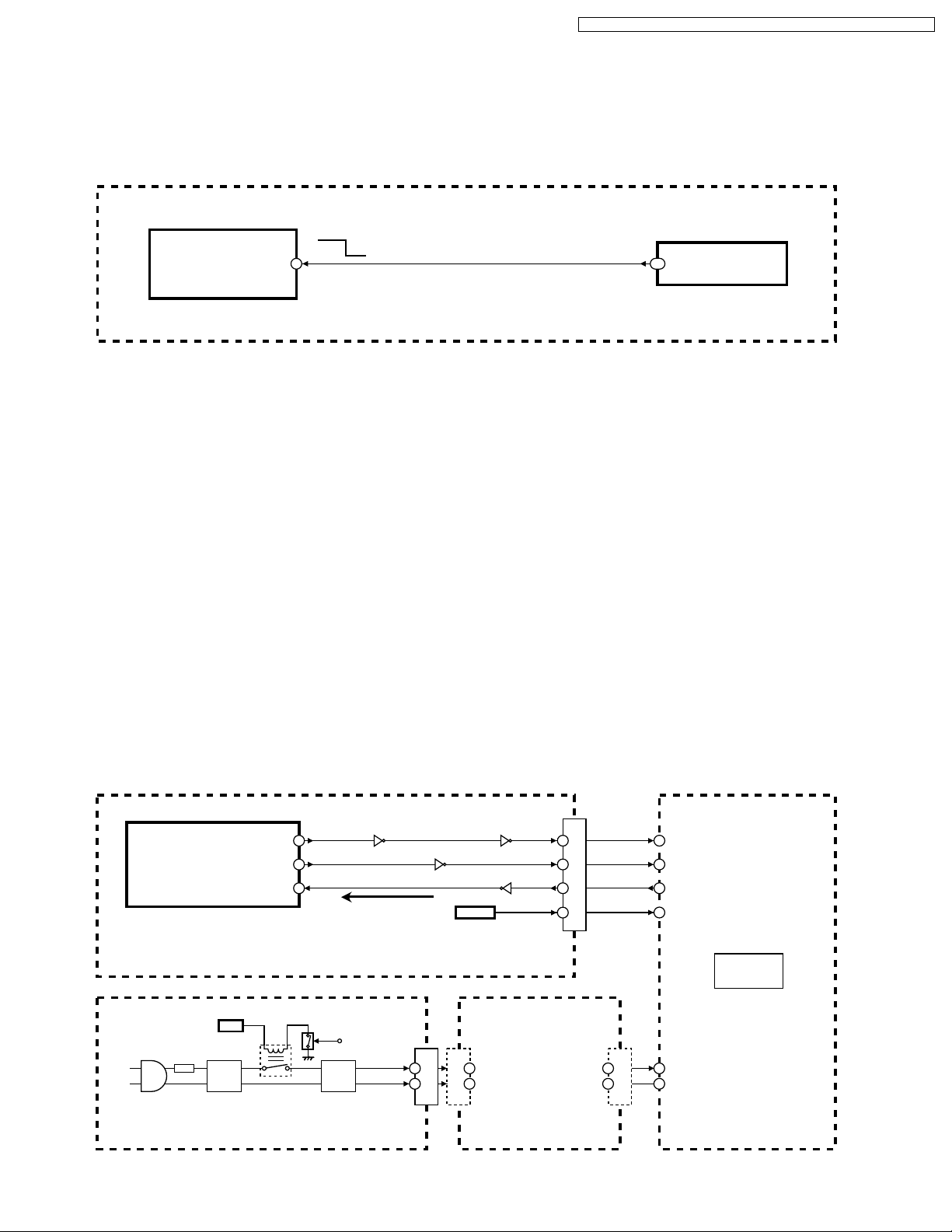
OPT Fan stops detection circuit
Front Fan or Rear Fan stops detection circuit
[LAMP Indicator eleven blinks]
[LAMP Indicator twelve blinks]
IC6004
(TV MICROCONTROLLER)
FAN SOS
LAMP FAN SOS
OPT FAN SOS
FRONT FAN SOS
REAR FAN SOS
NORMAL
REAR JACK P.C.B.
CONNECTION ERROR
117
:APPROX. 0V
:APPROX. 0.5V
:APPROX. 1.3V
:APPROX. 2V
:APPROX. 2.8V
:APPROX. 3.3V
29 29
CN3001
CN3501
Q2754
LAMP Fan stops detection circuit
Rear Fan or Front Fan stops detection circuit
Rear Jack P.C.B. connection error detection circuit
+9V
Q2752
IC2751
(+8 V)
DRIVE
4
+9V
Q2751
Q2753
2
5
IC2753
DRIVE
5
IC2754
DRIVE
(+6.0V~ +6.5 V)
42
(+7 V)
42
CN2751-1
CN2751-2
CN2751-3
CN2752-1
CN2752-2
CN2752-3
CN2754-1
CN2754-2
CN2754-3
CN2753-1
CN2753-2
CN2753-3
FRONT
FAN
REAR
FAN
OPT
FAN
LAMP
FAN
FRONT/REAR FAN SD CONTROL
<FROM TV MICROCONTROLLER (IC6004)>
OPT FAN SD CONTROL
<FROM TV MICROCONTROLLER (IC6004)>
MAIN P.C.B. REAR JACK P.C.B.
24
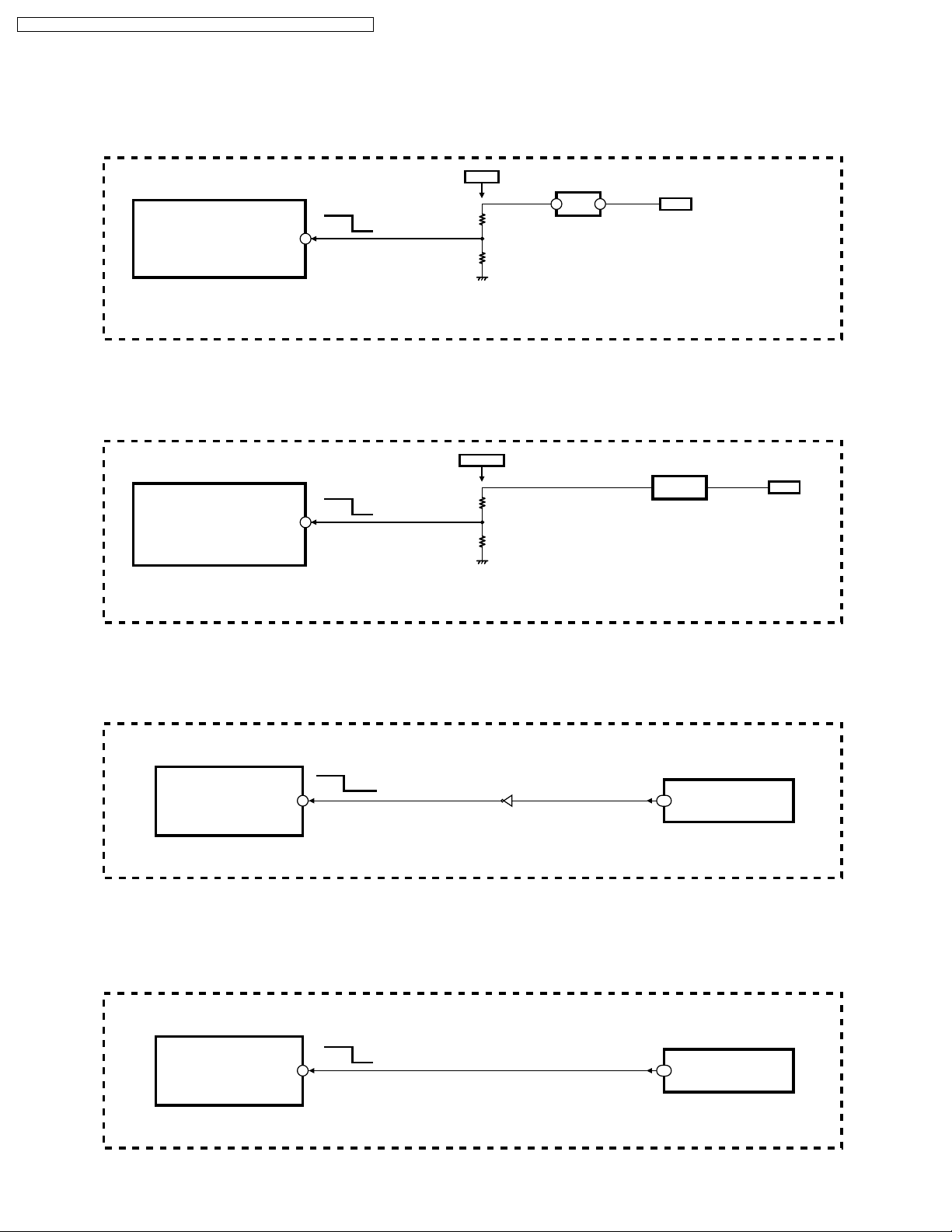
AC stop detection circuit
T801
2
9
7
3
6
D811
D802
FULL-WAVE
RECTIFIER
Q803-Q805
AC VOLT AGE
DETECT
POWER P.C.B. MAIN P.C.B.
Over current detection circuit
IC1001
(SWITCHING CONTROL)
STBY+7V
6 6
CN1003
CN1101
PT-50LCZ70 / PT-56LCZ70 / PT-61LCZ70 / PT-50LCZ7 / PT-56LCZ7 / PT-61LCZ7
IC6004
Normal
SOS
(TV MICROCONTROLLER)
12
AC STOP (L)
T1002
DRIVE
CONTROL
OVER
CURRENT
DETECT
Over current detect
POWER P.C.B.
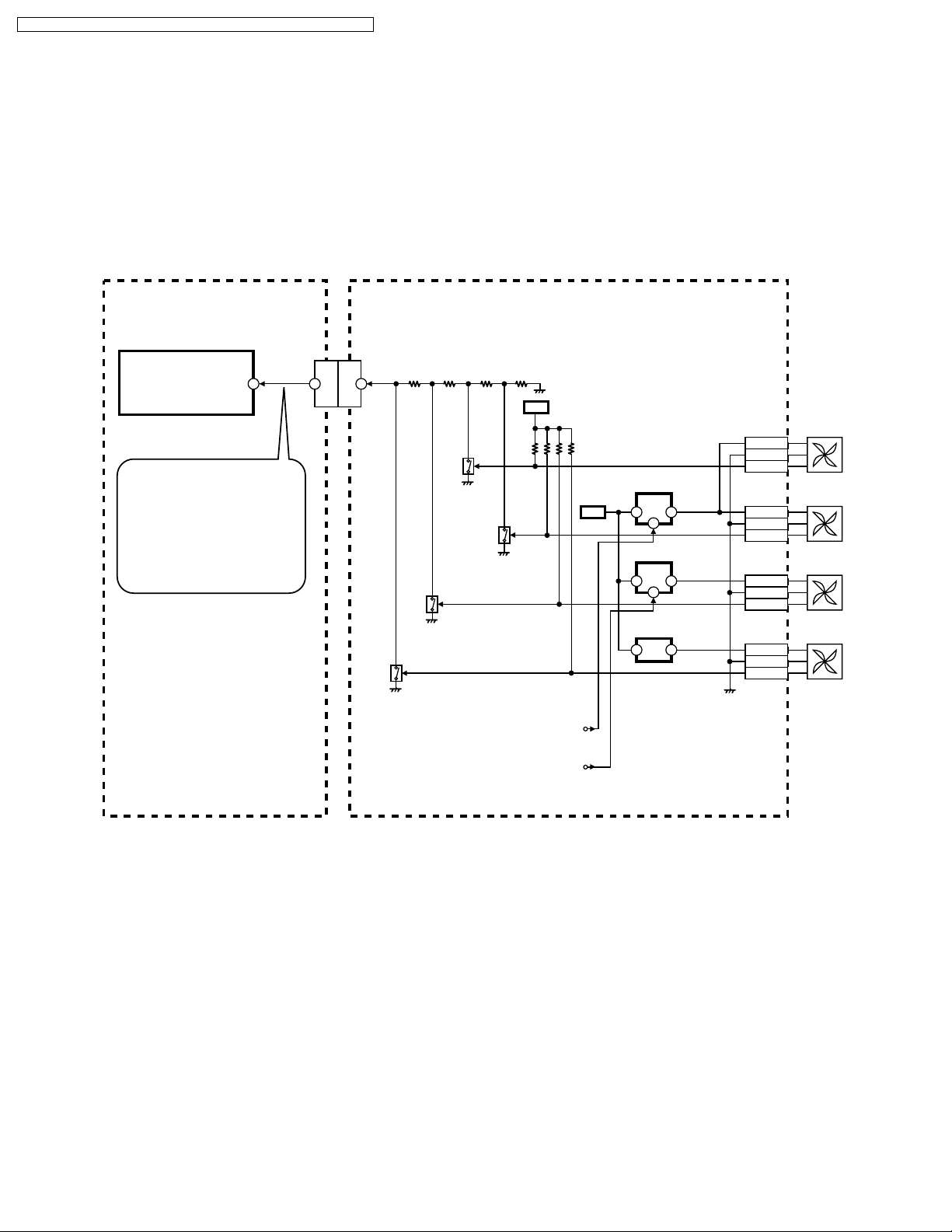
Abnormal Temperature (Thermal fuse) detection circuit
Q801
+12V
AC IN
F801
8A/125V
AC LINE
FILTER
RL801
F1001
6.3A/125V
MAIN
POWER
SUPPLY
CIRCUIT
9 14
5
8 8
CN1003
CN1101
1 2
CN1102
SWITCHING
TRANSFORMER
IC6004
(TV MICROCONTROLLER)
1
TV SUB ON(H)
MAIN P.C.B.
Q806
+12V
RL802
POWER P.C.B.
AC LINE
FILTER
TO RF AMP
POWER SUPPLY
P.C. B.
25
THERMAL
FUSE
(on Lamp)
(117 C/242.6 F)
PT-50LCZ70 / PT-56LCZ70 / PT-61LCZ70 / PT-50LCZ7 / PT-56LCZ7 / PT-61LCZ7
How to solve problems indicated by the Error Indication
(The symptom of all errors is that the Lamp goes off)
Note: Before performing troubleshooting, confirm that all connector cables in the unit are connected correctly.
POWER
Indicator
1
2
3
4
[POWER Indicator one blink]
The following voltage lines on the Main P.C.B. is over
current.
• SUB+5V line
• SUB+1.8V line
• SUB+3.3V line
• SUB+1.2V line
• DDR+3.3V line
• FHD+1.2V line
The following voltage lines on the Main P.C.B. is over
voltage.
• DT+9V line
• SUB+5V line
• SUB+1.8V line
• SUB+3.3V line
• SUB+1.2V line
• DDR+3.3V line
• FHD+1.2V line
[POWER Indicator two blinks]
DT+9V line error.
[POWER Indicator three blinks]
SUB+5V line error.
[POWER Indicator four blinks]
MAIN+3.3V line error.
Problem Possible Solution
1. Replace the Power P.C.B.
2. If still NG, replace the OPT/TV Unit.
1. Check that Connector CN1102 (Thermal Fuse) on the Main P.C.B. is connected firmly.
2. If still NG, replace the Power P.C.B.
3. If still NG, replace the OPT/TV Unit.
1. Replace the OPT/TV Unit.
6
7
9
[POWER Indicator six blinks]
AUDIO AMP (IC4501) failure
[POWER Indicator seven blinks]
Communication error between Peaks (IC8001) and
TV microcontroller (IC6004) on the Main P.C.B.
[POWER Indicator nine blinks]
Communication error between Peaks (IC8001) and
TV microcontroller (IC6004) on the Main P.C.B.
26
PT-50LCZ70 / PT-56LCZ70 / PT-61LCZ70 / PT-50LCZ7 / PT-56LCZ7 / PT-61LCZ7
How to solve problems indicated by the Error Indication
(The symptom of all errors is that the Lamp goes off)
Note: Before performing the troubleshooting, confirm that all connector cables in the unit are connected correctly.
LAMP
Indicator
2
3
4
5
8
9
10
11
12
13
[LAMP Indicator two blinks]
Lamp does not light up.
[LAMP Indicator three blinks]
Lamp failure (Internal Lamp thermistor open or short).
[LAMP Indicator four blinks]
Abnormal Lamp temperature (more than 92 ˚C).
[LAMP Indicator five blinks]
Lamp communication error.
[LAMP Indicator eight blinks]
Cooling Fan (Lamp Fan) malfunction.
[LAMP Indicator nine blinks]
Cooling Fan (OPT Fan) malfunction.
[LAMP Indicator ten blinks]
Cooling Fan (Front Fan or Rear Fan) malfunction.
[LAMP Indicator eleven blinks]
Cooling Fan (Rear Fan or Front Fan) malfunction.
[LAMP Indicator twelve blinks]
Rear Jack P.C.B. connection error.
[LAMP Indicator thirteen blinks]
Abnormal Lamp input voltage (+26V)
Normal: +26V
Abnormal: less than +20V
Problem Possible Solution
1. Try to turn on the power several times. (Wait 5 minutes before retrying.)
2. If still NG, replace the Lamp Unit.
1. Try to turn on the power several times. (Wait 5 minutes before retrying.)
2. If still NG, replace the Lamp Unit.
1. Relocate the unit to a proper location.
Keep the unit at least 100 mm (4") away from the wall to provide proper ventilation
because warm air is discharged. Blocking the ventilation opening of the cooling fan may
damage the unit.
2. Wait until the Lamp has cooled off (approximately 1 hour) and try to turn on the power several times.
3. If still NG, check whether the Fans rotate normally.
4. If still NG, replace the Lamp Unit.
1. Try to turn on the power several times. (Wait 5 minutes before retrying.)
2. If still NG, check that the cable between CN6005 on the Main P.C.B. and Lamp Unit is
connected firmly.
1. Check that Connector CN2753 on the Rear Jack P.C.B. is connected firmly.
2. If still NG, replace the Lamp Fan.
1. Check that Connector CN2754 on the Rear Jack P.C.B. is connected firmly.
2. If still NG, replace the OPT/TV Unit (Fan Case Unit (OPT Fan)).
1. Check that Connector CN2751 or CN2752 on the Rear Jack P.C.B. is connected firmly.
2. If still NG, check whether the Front Fan or Rear Fan stopped and replace it.
1. Check that Connector CN2752 or CN2751 on the Rear Jack P.C.B. is connected firmly.
2. If still NG, check whether the Front Fan or Rear Fan stopped and replace it.
1. Check that Connector CN3501 on the Rear Jack P.C.B. is connected into Connector
CN3001 on the Main P.C.B. firmly.
1. Try to turn on the power several times. (Wait 5 minutes before retrying.)
2. If still NG, check that Connector CN1 and CN151 on the RF AMP Power Supply P.C.B. are
connected firmly.
3. If still NG, unplug the AC Cord and disconnect CN151 connector cable and check
voltage at Pin 1, 2 or 3 of CN151 on the RF AMP Power Supply P.C.B. See Figure a.
If OK (+26V), replace the Lamp Unit.
If NG, check the voltage between Pin 1 and Pin 2 of CN1 on the RF AMP Power Supply P.C.B.
If OK (AC120V), replace the RF AMP Power Supply P.C.B.
If NG, replace the Power P.C.B.
(Note: They are same Fan.)
(Note: They are same Fan.)
27
PT-50LCZ70 / PT-56LCZ70 / PT-61LCZ70 / PT-50LCZ7 / PT-56LCZ7 / PT-61LCZ7
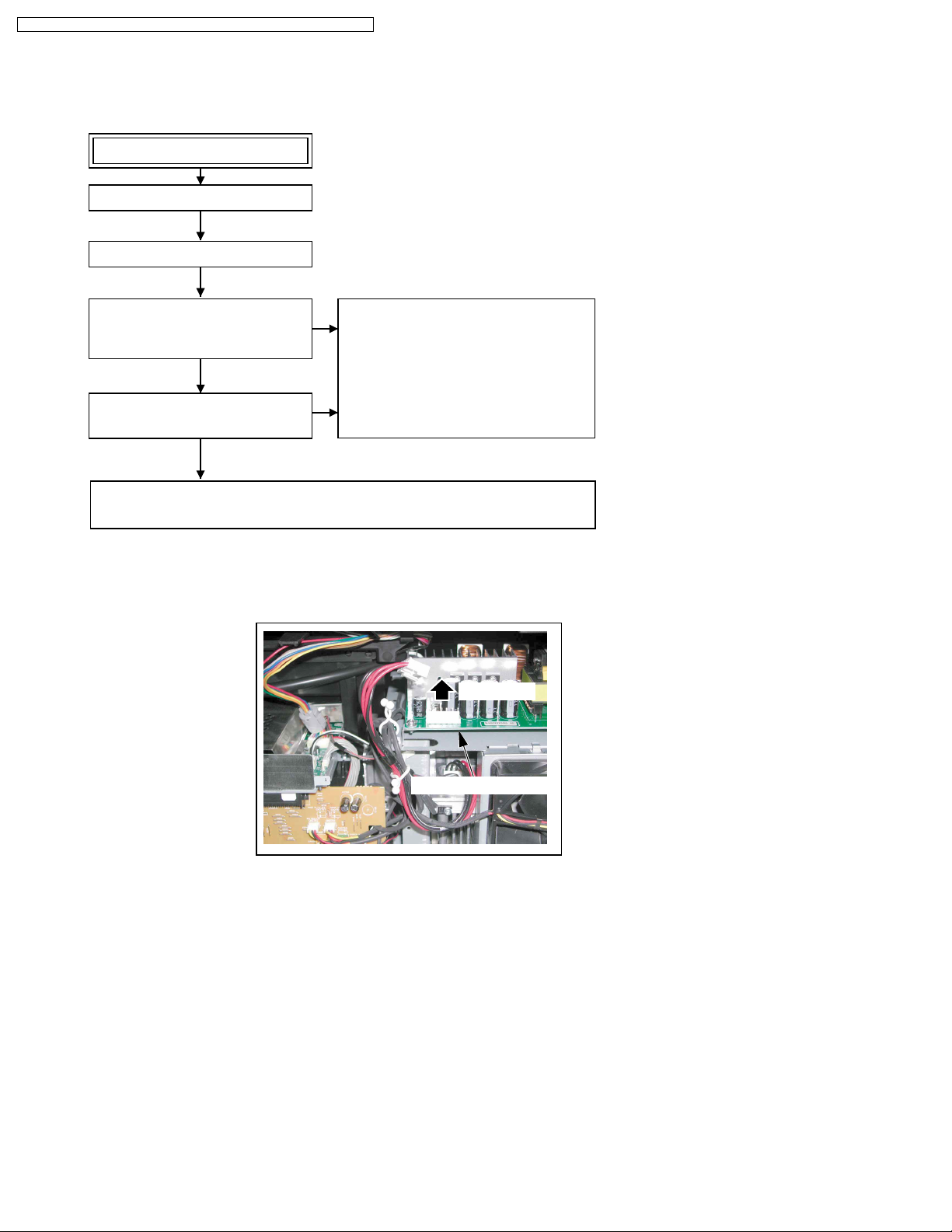
LAMP DOES NOT LIGHT UP
Plug in the AC Cord.
Note:
1.Before performing troubleshooting, confirm that all
2.When repeating troubleshooting, be sure to
3.If the same error indication repeatedly occurs
Turn the power on.
Is there a snap sound of the Relay
turning ON ?
(Relay: RL801/RL802 on the Power
P.C .B. )
YES
Does the Power Indicator (D6803) on
the Power Switch/Operation P.C.B. flash
green?
YES
Power/Lamp Indicator flashes continuously.
Refer to "How to solve problems indicated by the Error Indication."
Perform troubleshooting.
The Power P.C.B. is defective.
NO
Replace the Power P.C.B.
NO
connector cables are connected properly.
turn the power off and unplug the AC Cord.
after several attempts, proceed to the next step.
Pin 1,2 or 3 of CN151
Figure. a
Disconnect
28
PT-50LCZ70 / PT-56LCZ70 / PT-61LCZ70 / PT-50LCZ7 / PT-56LCZ7 / PT-61LCZ7
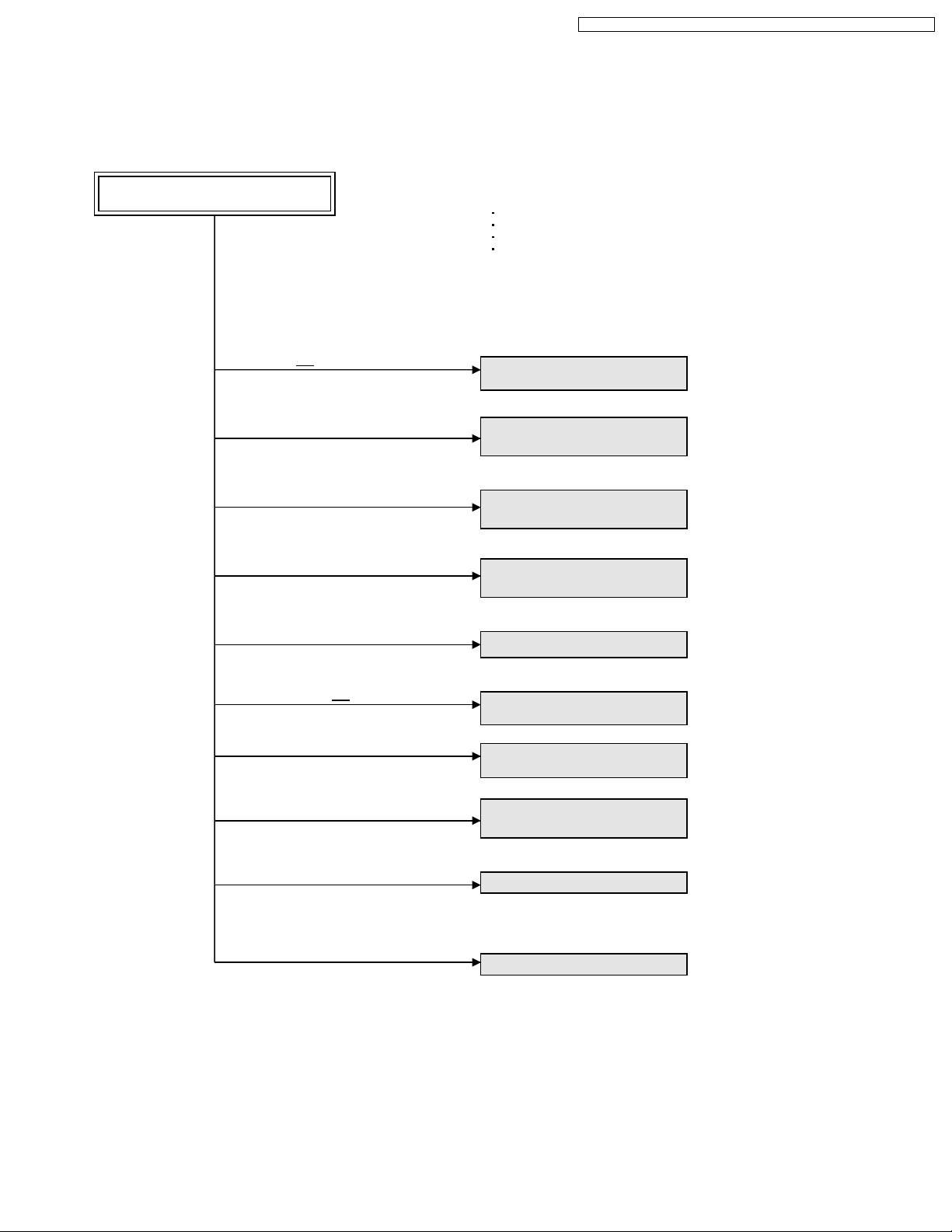
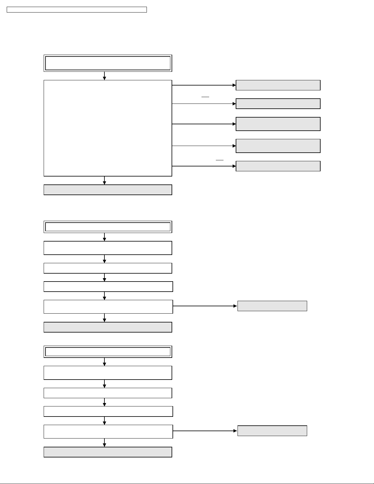
HOW TO DETERMINE WHICH P.C.B. IS DEFECTIVE
No picture or abnormal picture
(Only Video1 OR 2 input is NG.)
(Only Video3 input is NG.)
(Only S-VIDEO 1 input is NG.)
(Only tuner Analog CH input is NG.)
(Only PC input is NG.)
ABNORMAL PICTURE:
No Picture Color (Black and White picture)
Abnormal Picture Color
Unsynchronized Picture
Dark Picture
Replace the OPT/TV Unit or the
Rear Jack P.C.B.
Replace the Front Jack/Operation
P.C.B. or the OPT/TV Unit.
Replace the OPT/TV Unit or the
Rear Jack P.C.B.
Replace the Tuner P.C.B. or the
OPT/TV Unit.
Replace the OPT/TV Unit.
(Only Component 1 OR 2 input is NG.)
(Only Digital Tuner input is NG.)
(Only HDMI3 or SD Card input is NG.)
(Only HDMI1 or HDMI2 is NG.)
(All inputs are NG.)
Replace the OPT/TV Unit or the
Rear Jack P.C.B.
Replace the Tuner P.C.B. or the
OPT/TV Unit.
Replace the SD/HDMI P.C.B. or the
OPT/TV Unit.
Replace the OPT/TV Unit.
Replace the OPT/TV Unit.
29
PT-50LCZ70 / PT-56LCZ70 / PT-61LCZ70 / PT-50LCZ7 / PT-56LCZ7 / PT-61LCZ7
No sound from built-in both L-CH and
R-CH Speakers
Check that there is an audio signal to the Audio Out
Terminal from all input terminals.
OK
Replace the OPT/TV Unit or Power P.C.B.
No sound from built-in L-CH Speaker only
Press MENU key on the remote and select
"Audio" in MENU screen. Then press "OK."
(All input are NG.)
(Only Audio1 OR Audio2
input is NG.)
(Only Audio3 input is NG.)
(Only Tuner input is NG.)
(Only Component 1 OR
Component 2 input is NG.)
Replace the OPT/TV Unit
Replace the Rear Jack P.C.B.
Replace the Rear Jack P.C.B. or
Front Jack/Operation P.C.B.
Replace the OPT/TV Unit or
Tuner P.C.B.
Replace the Rear Jack P.C.B.
Does the "BALANCE" screen becomes center position?
NO
Set to the center position.
Still NG
Swap the Speaker Connectors to confirm the Speaker
failure.
NO
Replace the OPT/TV Unit.
No sound from built-in R-CH Speaker only
Press MENU key on the remote and select
"Audio" in MENU screen. Then press "OK."
Does the "BALANCE" screen becomes center position?
NO
Set to the center position.
Still NG
Swap the Speaker Connectors
to confirm the Speaker failure.
NO
Replace the OPT/TV Unit.
YES
YES
Replace the L-CH Speaker.
Replace the R-CH Speaker.
30
 Loading...