

Panasonic PS-2000ST Operating Instructions Manual
Operating
Instructions
VmeOCIPHERRS
Descrambler
Compatible
I®
VIDEOpal
Order
Recorder
|
Integrated
Satellite
Receiver
Modei
No.
PS-2000ST
Panasonic
®
Read
these
instructions
completely
before
operating
this
unit.
TQB510184
Dear
Panasonic
Customer
Congratulation
on
your
purchase
of a new
Panasonic
Integrated
Satellite
Receiver
[PS-2000ST].
This
receiver
is
compatible
with
the
VideoCipher
RS
descrambler
and
VIDEOpal
order
recorder
module""'
and
is
provided
with a variety
of
new
functions.
It
represents
the
state-of
the-art
in
your
television
viewing.
'''
VideoCiphet®
RS
and
VIDEOpal®
order
recorder
are
registered
trademarks
of
General
Instrument
Corporation.
Modules
will
be
supplied
and
warranteed
by
your
dealer
or
program
provider.
Customer's
Record
Model
Number
PS-2000ST
Serial
Number
Address
Number
(VCRS)
Unit/Phone
Nos.*^)
/
Date
of
Purchase
Dealer
Name
TEL:
See
the
operating
instructions
of
VideoCipher
RS.
Contents
important
Safety
Notice
2
General
Description/Accessories
3
Location
Front
Controls
and
Indicators
4
Rear
Controls
and
Terminals
5
UHF
Remote
Control
7
Battery
Replacement/
Optional
Remote
Control
[RMC-40SR]
9
Connections
Basic
Diagram
10
Antenna
Actuator
11
UHF
Antenna
11
Low
Noise
Block
Down
Converter
11
Programming
and
Operations
Information
12
Programming:
Set
up
15
Programming
Note
20
Reprogramming
Satellite
Addition
21
To
Reposition a Satellite
23
To
Delete a Satellite
24
Operations
Daily
Operations
25
Favorite
Channel
Operations
27
Picture
Adjust
Operations
29
Audio
Operations
31
Useful
Functions
Skip
Channel
32
Parental
Lock
33
Diagnostics
35
Troubleshooting
36
Specifications
37
Criminal
Warning
38
Warranty
38
-1
-
Important
Safety
Notice
WARNING:
To
prevent
damage
which
may
result
in
fire
or
shock
hazard,
do
not
expose
this
appliance
to
rain
or
moisture.
WARNING:
This
equipment
generates
and
uses
radio
frequency
energy
and
if
not
installed
and
used
properly,
that
is,
in
strick
accordance
with
the
manufacture's
instructions,
may
cause
interference
to
radio
and
television
reception.
It
has
been
type
tested
and
found
to
comply
with
the
limits
for a TV
interface
device
in
accordance
with
the
specifications
in
part
15
of
FCC
Rules,
which
are
designed
to
provide
reasonable
protection
against
such
interference
in a residential
installation.
However,
there
is
no
guarantee
that
interference
will
not
occur
in a particular
installation.
If
this
equipment
does
cause
interference
to
radio
or
television
reception,
which
can
be
determined
by
turning
the
equipment
off
and
on,
the
user
is
encouraged
to
try
to
correct
the
interference
by
one
or
more
of
the
following
measures:
Reorient
the
receiving
antenna
Relocate
the
equipment
with
respect
to
the
receiver
Move
the
equipment
away
from
the
receiver
Plug
the
equipment
into a different
outlet
so
that
equipment
and
receiver
are
on
different
branch
circuits.
If
necessary,
the
user
should
consult
the
dealer
or
an
experienced
radio/television
technician
for
additional
suggestions.
The
user
may
find
the
following
booklet
helpful:
"Something
about
interference"
which
is
available
from
FCC
regional
offices.
CAUTION:
Do
not
change
or
modify
without
the
express
approval
of
the
party
responsible
for
compliance.
These
changes
or
modifications
could
void
the
user's
authority
to
operate
this
equipment.
CAUTION:
Do
not
remove
the
grounding
pin
on
the
power
plug.
This
equipment
is
equipped
with a three
grounding-type
power
plug.
This
plug
will
only
fit a grounding-type
power
outlet.
This
is a safety
feature.
If
you
are
unable
to
insert
the
plug
into
the
outlet,
contact
an
electrician.
Do
not
defeat
the
purpose
of
the
grounding
plug.
Do
not
remove
CAUTION
RISK
OF
ELECTRIC
SHOCK
DO
NOT
OPEN
CAUTION;
TO
REDUCE
THE
RISK
OF
ELECTRIC
SHOCK.
DO
NOT
REMOVE
COVER
(OR
BACK)
NO
USER-SERVICEABLE
PARTS
INSIDE
REFER
SERVICING
TO
QUALIFIED
SERVICE
PERSONNEL
The
lightning
flash
with
arrowhead
symbol,
within
an
equilateral
triangle,
is
intended
to
alert
the
user
to
the
presence
of
uninsulated
"dangerous
voltage"
within
the
product's
enclosure
that
may
be
of
sufficient
magnitude
to
constitute a risk
of
electric
shock
to
persons.
The
exclamation
point
within
an
equilateral
triangle
is
intended
to
alert
the
user
to
the
presence
of
important
operating
and
maintenance
(servicing)
instructions
in
the
literature
accompanying
the
appliance.
Note
to
CATV
system
installer:
This
reminder
is
provided
to
call
the
CATV
system
Installer's
attention
to
Article
820-40
of
the
NEC
that
provides
guidelines
for
proper
grounding
and,
in
particular,
specifies
that
the
cable
ground
shall
be
connected
to
the
grounding
system
of
the
building,
as
close
to
the
point
of
cable
entry
as
practical.
-2-
General
Description
Panasonic
Integrated
Satellite
Receiver
The
PS-2000ST
is a high-end
feature
packed,
Integrated
Satellite
Receiver
offered
by
Panasonic.
It
combines
Panasonic's
receiver,
television
and
audio
expertise
to
offer
superb
video
and
audio
performance
from
Satellite
broadcast
programs.
Standard
UHF
remote
control
provides
out-of-room
satellite
or
channel
selection.
Features
and
Capabilities
•
Compatible
with
VideoCipher®
Descrambler
and
Videopal
Order
Recorder
modules
•
Built-in
Programmable
Actuator
Controller
with
48
satellite
memory
•
27
User
programmable
favorite
channels
•
Frequency
tuning
plans
for
all
major
Ku
Band
Satellites
•
Direct
Satellite
access
•
Auto
peak
adjustments
for
dish
and
skew
•
Built-in
programmable
Tl
filter
•
Sophisticated
on-screen
display
with
satellite
graphics
Full
function
UHF
remote
control
Optional
simplified
UHF
remote
control
available
Digital
Stereo
Sound
on
VideoCipher
channels
Parental
lock
with
programmable
password
and
unique
one
time
view
function
Skip-channel
tuning
Second
Receiver
Operation
Last
Channel
Recall
Automatic
Memory
remembers
last
control
settings
Programmable
AFC
ON/OFF
with
video
fine
tuning
Video
scan
mode
Built
in
RF
modulator
with
channel
3/4
switch
Compatible
with
LNBF
units
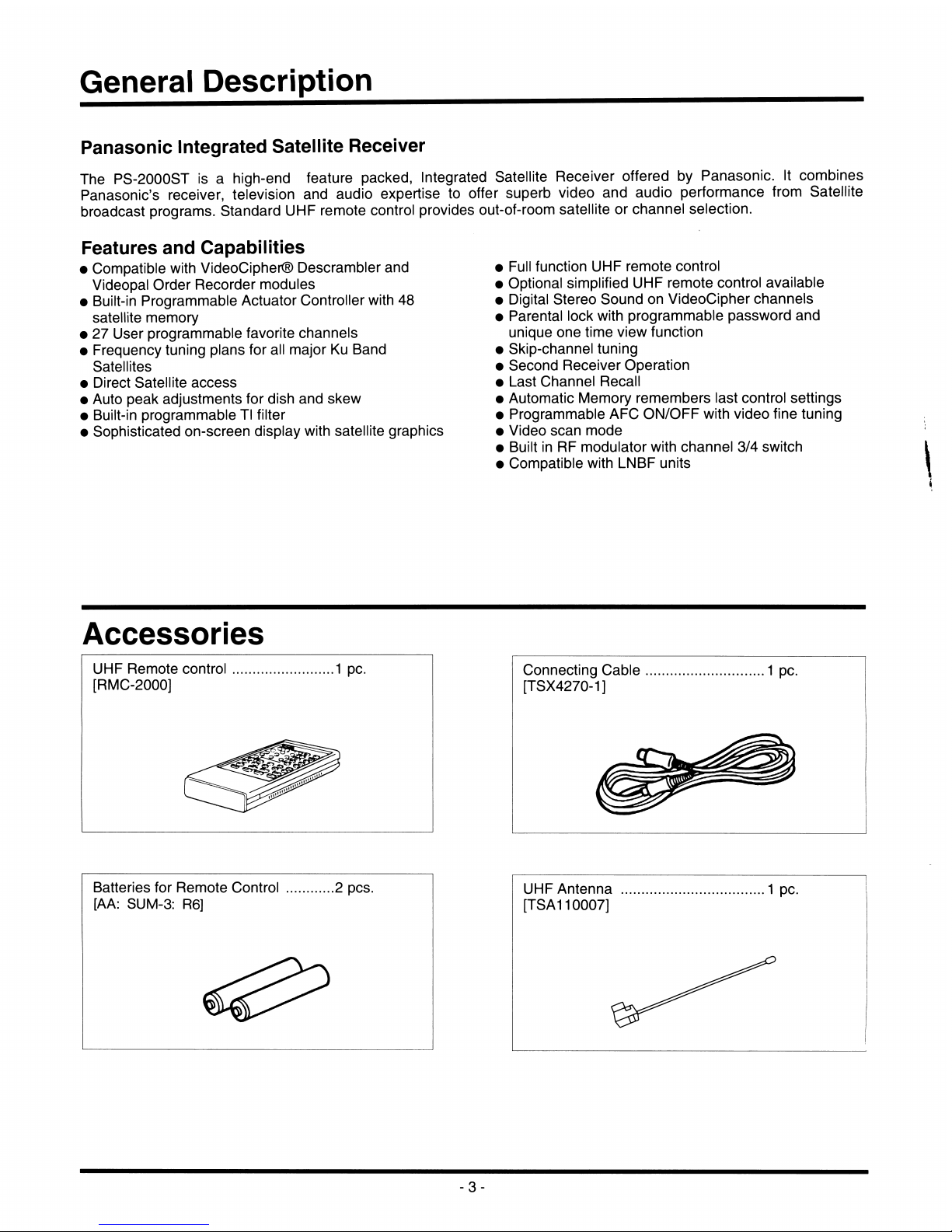
Accessories
UHF
Remote
control
[RMC-2000]
1
pc.
Connecting
Gable
1
pc.
[TSX4270-1]
Batteries
for
Remote
Control
2
pos.
[AA:
SUM-3:
R6]
UHF
Antenna
[TSA110007]
. 1 pc.
-3-
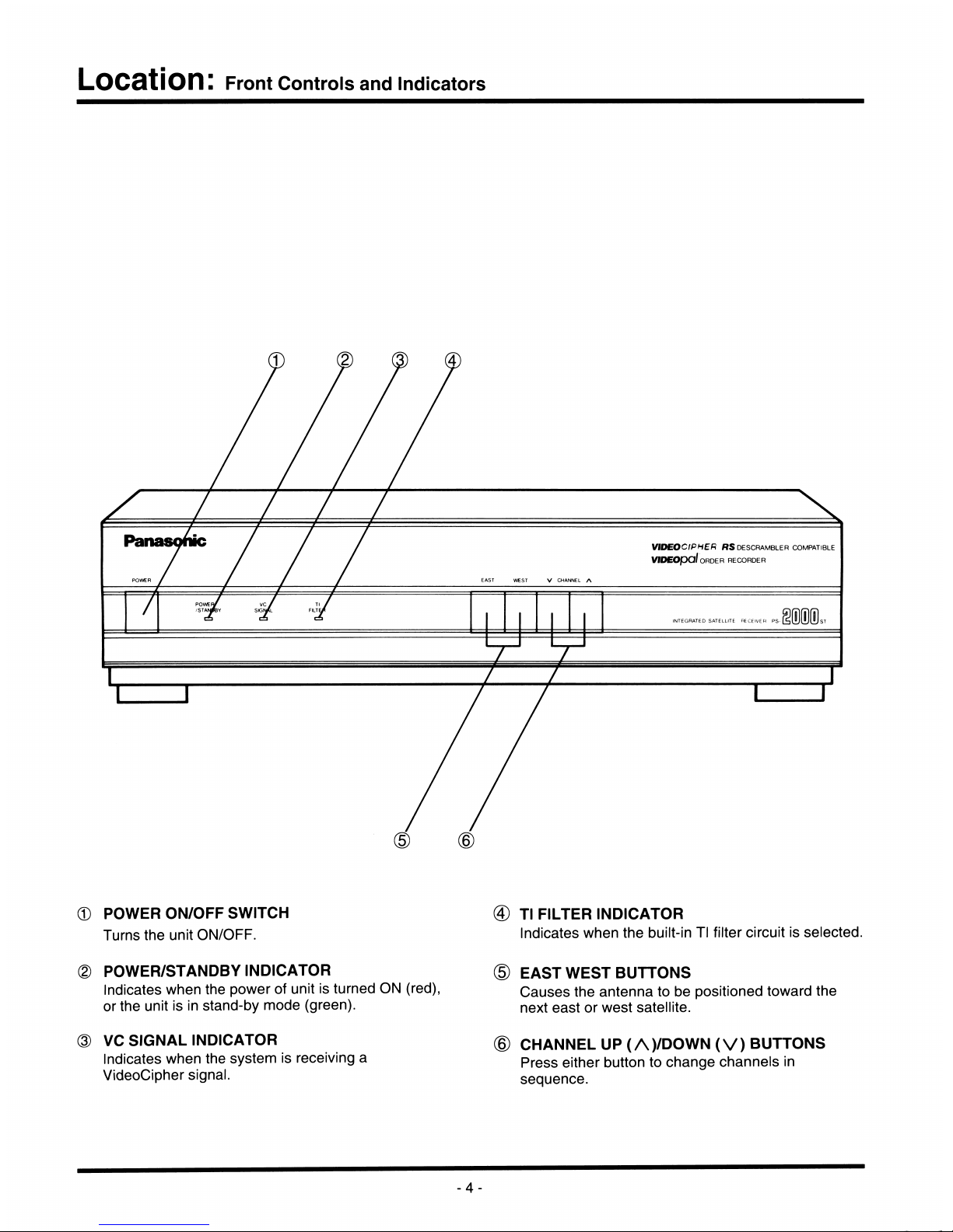
Location:
Front
Controls
and
Indicators
ViDEOCIPHtH
#?S
DESCRAMBLER
COMPATIBLE
VIDEOpol
ORDER
RECORDER
®
POWER
ON/OFF
SWITCH
Turns
the
unit
ON/OFF.
(D
Tl
FILTER
INDICATOR
Indicates
when
the
built-in
Tl
filter
circuit
is
selected.
POWER/STANDBY
INDICATOR
Indicates
when
the
power
of
unit
is
turned
ON
(red),
or
the
unit
is
in
stand-by
mode
(green).
VC
SIGNAL
INDICATOR
Indicates
when
the
system
is
receiving
a
VideoCipher
signal.
EAST
WEST
BUTTONS
Causes
the
antenna
to
be
positioned
toward
the
next
east
or
west
satellite.
CHANNEL
UP
(A)/DOWN
(V)
BUTTONS
Press
either
button
to
change
channels
in
sequence.
-4-
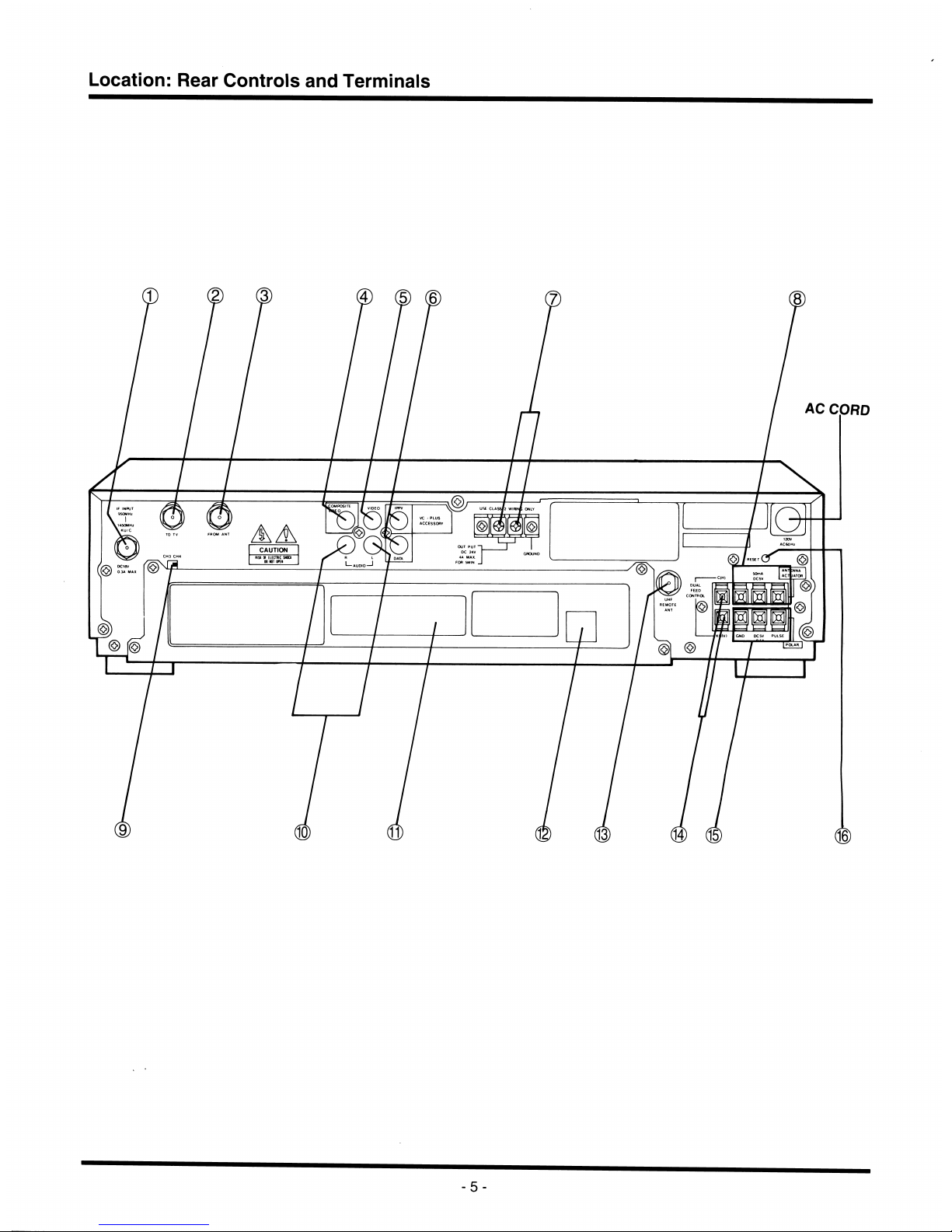
Location:
Rear
Controls
and
Terminals
AC
CORD
CAUTION
I—AUDIO—'
-5-

®
IF
INPUT/+18V
DC
OUTPUT
TERMINAL
Ku/C
[F
connector]
Input
connector
for
IF
signal
from
LNB,
and
also
supplies a +18V
DC
power
to
tfie
LNB.
@
TV
RF
OUTPUT
TERMINAL
[F
connector]
VHF
signal
to
television
set.
@
EXT.
ANTENNA
INPUT
TERMINAL
[F
connector]
VHF
signal
from
an
external
VHF
antenna
@
COMPOSITE
OUTPUT
TERMINAL
[RCA
connector]
Composite
baseband
signal
to
otfier
descramblers.
(D
VIDEO
OUTPUT
TERMINAL
[RCA
connector]
Video
signal
to
video
monitor.
(D
VIDEOCIPHER
(IPPV/DATA)
TERMINALS
RCA
connector
for
future
applications.
@
+24V/-24V
DC
OUTPUT
TERMINALS
(TO
ACTUATOR)
+24V
and
-24V
DC
output
to
actuator
motor
(§)
ANTENNA
ACTUATOR
CONTROL
TERMINALS
GND
Signal
ground
conductor
from
actuator.
DC5V
50mA
5V
DC
(50mA)
output
to
supply
Hall
sensor
or
Optical
type
in
actuator.
PULSE
Actuator
sensor
pulse
output.
(Reed
switch,
Hall
sensor
or
Optical
type)
(D
CHANNEL
SELECT
SWITCH(CH3/CH4)
Selects
channel 3 or
channel 4 output
of
PS-
2000ST
to
the
television.
Choose
the
channel
that
is
not
broadcast
locally
and
tune
the
television
to
this
channel.
®
AUDIO
OUTPUT
TERMINALS
[RCA
connector]
Audio
signals
(L/R)
to
video
monitor
or
external
audio
amplifier.
©
VIDEOCIPHER
ADDRESS
NO.
You
can
read
the
first 8 numbers
of
your
Authoriza
tion
(Address)
Number
through
this
window.
See
the
operating
instruction
of
VideoCipher
RS
for
directions
to
read
the
full
12-digit
number.
Use
this
number
for
program
subscription.
®
MODEM
TELEPHONE
JACK
LOCATION
For
videopal
operation.
®
UHF
REMOTE
ANTENNA
CONNECTING
TERMINAL
[F
connector]
Connector
for
UHF
remote
antenna.
®
DUAL
FEED
CONTROL
VOLTAGE
TERMINALS
Control
voltage
output
to
control
external
V/H
switch.
©
POLARIZATION
CONTROL
SIGNAL
TERMINALS
Polarization
control
signals
to
polarizer.
©
RESET
BUTTON
Built-in
circuit
breaker
for
overcurrent
or
short
circuit
protection.
Press
button
to
reset
the
breaker.
-6-
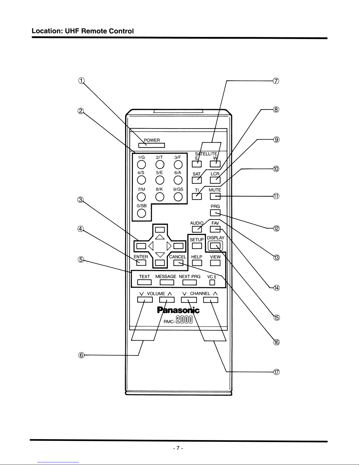
Location;
UHF
Remote
Control
POWER
SyXTELLITE
o o
o
SATX
LCR
o o o
7/M
8/K
9/GS
MUTE
Q
o
o o
AUDIOX
FAV
DISPLAY
ENTER
CANCEL
HELP
VIEW
□
□
TEXT
MESSAGE
NEXT
PRG
VCH
□
V
VOLUME
A
V
CHANNEL
A
nasoilM
rmc-§®®(!)\
-7-
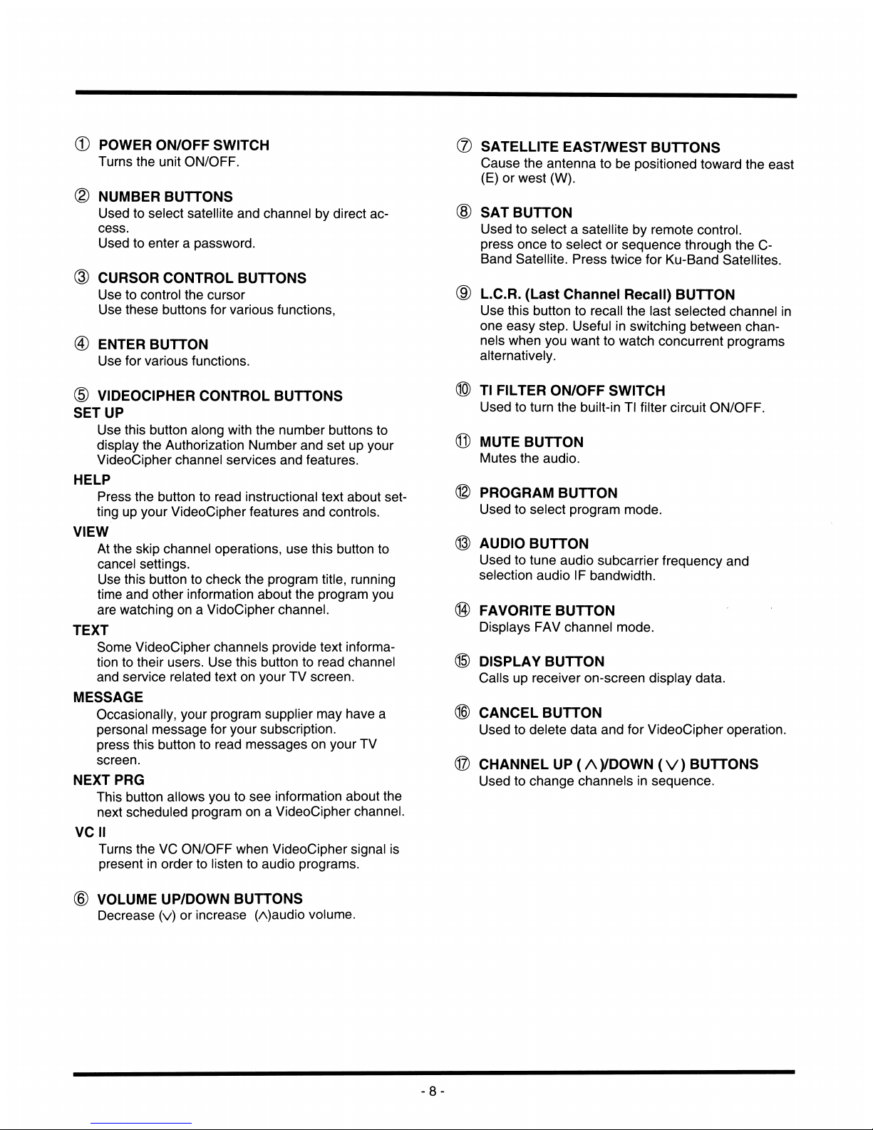
©
POWER
ON/OFF
SWITCH
Turns
the
unit
ON/OFF.
(D
NUMBER
BUTTONS
Used
to
select
satellite
and
channel
by
direct
ac
cess.
Used
to
enter a password.
@
CURSOR
CONTROL
BUTTONS
Use
to
control
the
cursor
Use
these
buttons
for
various
functions,
@
ENTER
BUTTON
Use
for
various
functions.
(D
VIDEOCIPHER
CONTROL
BUTTONS
SETUP
Use
this
button
along
with
the
number
buttons
to
display
the
Authorization
Number
and
set
up
your
VideoCipher
channel
services
and
features.
HELP
Press
the
button
to
read
instructional
text
about
set
ting
up
your
VideoCipher
features
and
controls.
VIEW
At
the
skip
channel
operations,
use
this
button
to
cancel
settings.
Use
this
button
to
check
the
program
title,
running
time
and
other
information
about
the
program
you
are
watching
on a VidoCipher
channel.
TEXT
Some
VideoCipher
channels
provide
text
informa
tion
to
their
users.
Use
this
button
to
read
channel
and
service
related
text
on
your
TV
screen.
MESSAGE
Occasionally,
your
program
supplier
may
have
a
personal
message
for
your
subscription,
press
this
button
to
read
messages
on
your
TV
screen.
NEXT
PRO
This
button
allows
you
to
see
information
about
the
next
scheduled
program
on a VideoCipher
channel.
VC
II
Turns
the
VC
ON/OFF
when
VideoCipher
signal
is
present
in
order
to
listen
to
audio
programs.
©
VOLUME
UP/DOWN
BUTTONS
Decrease
(v)
or
increase
(A)audio
volume.
®
SATELLITE
EAST/WEST
BUTTONS
Cause
the
antenna
to
be
positioned
toward
the
east
(E)
or
west
(W).
®
SAT
BUTTON
Used
to
select a satellite
by
remote
control,
press
once
to
select
or
sequence
through
the
C-
Band
Satellite.
Press
twice
for
Ku-Band
Satellites.
©
L.C.R.
(Last
Channel
Recall)
BUTTON
Use
this
button
to
recall
the
last
selected
channel
in
one
easy
step.
Useful
in
switching
between
chan
nels
when
you
want
to
watch
concurrent
programs
alternatively.
®
Tl
FILTER
ON/OFF
SWITCH
Used
to
turn
the
built-in
Tl
filter
circuit
ON/OFF.
®
MUTE
BUTTON
Mutes
the
audio.
®
PROGRAM
BUTTON
Used
to
select
program
mode.
®
AUDIO
BUTTON
Used
to
tune
audio
subcarrier
frequency
and
selection
audio
IF
bandwidth.
@
FAVORITE
BUTTON
Displays
FAV
channel
mode.
®
DISPLAY
BUTTON
Calls
up
receiver
on-screen
display
data.
®
CANCEL
BUTTON
Used
to
delete
data
and
for
VideoCipher
operation.
®
CHANNEL
UP
(A)/DOWN(V)
BUTTONS
Used
to
change
channels
in
sequence.
-8-
Battery
Replacement
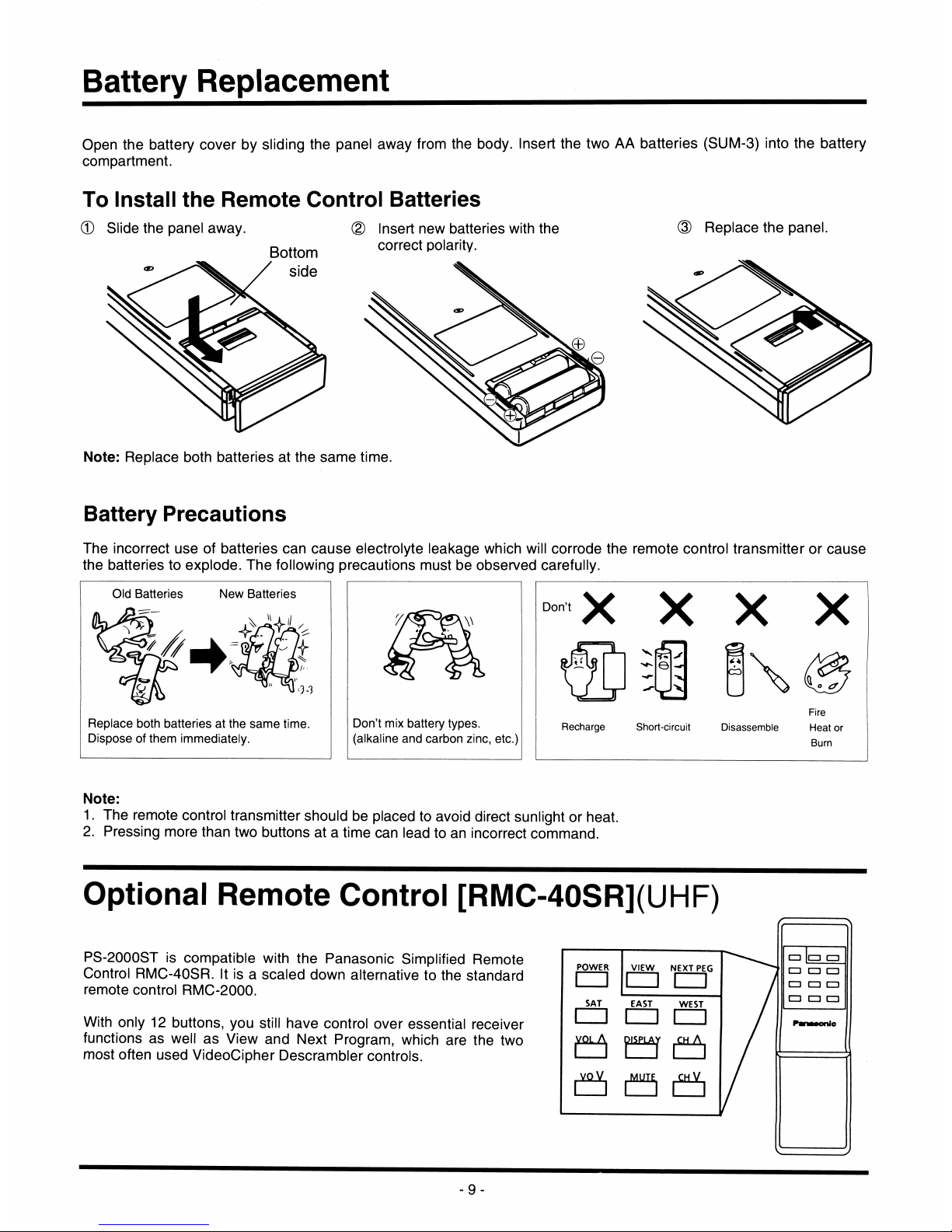
Open
the
battery
cover
by
sliding
the
panel
away
from
the
body.
Insert
the
two
AA
batteries
(SUM-3)
into
the
battery
compartment.
To
Install
the
Remote
Control
Batteries
d)
Slide
the
panel
away.
Bottom
side
@
Insert
new
batteries
with
the
correct
polarity.
Replace
the
panel.
Note:
Replace
both
batteries
at
the
same
time.
Battery
Precautions
The
incorrect
use
of
batteries
can
cause
electrolyte
leakage
which
will
corrode
the
remote
control
transmitter
or
cause
the
batteries
to
explode.
The
following
precautions
must
be
observed
carefully.
New
Batteries
Old
Batteries
Replace
both
batteries
at
the
same
time.
Dispose
of
them
immediately.
Don't
mix
battery
types,
(alkaline
and
carbon
zinc,
etc.)
Don't
X
X
X
X
Recharge
Short-circuit
Disassemble
Fire
Heat
or
Burn
Note:
1.
The
remote
control
transmitter
should
be
placed
to
avoid
direct
sunlight
or
heat.
2.
Pressing
more
than
two
buttons
at a time
can
lead
to
an
incorrect
command.
Optional
Remote
Control
[RMC-40SR](UHF)
PS-2000ST
is
compatible
with
the
Panasonic
Simplified
Remote
Control
RMC-40SR.
It
is a scaled
down
alternative
to
the
standard
remote
control
RMG-2000.
With
only
12
buttons,
you
still
have
control
over
essential
receiver
functions
as
well
as
View
and
Next
Program,
which
are
the
two
most
often
used
VideoCipher
Descrambler
controls.
POWER
VIEW
NEXT
PEG
□
□
!=□
SAT
EAST
WEST
CD
□
j)iSPLAjr
^CH
a
^
MUTE^
^
CH
V^
-9-
Connections
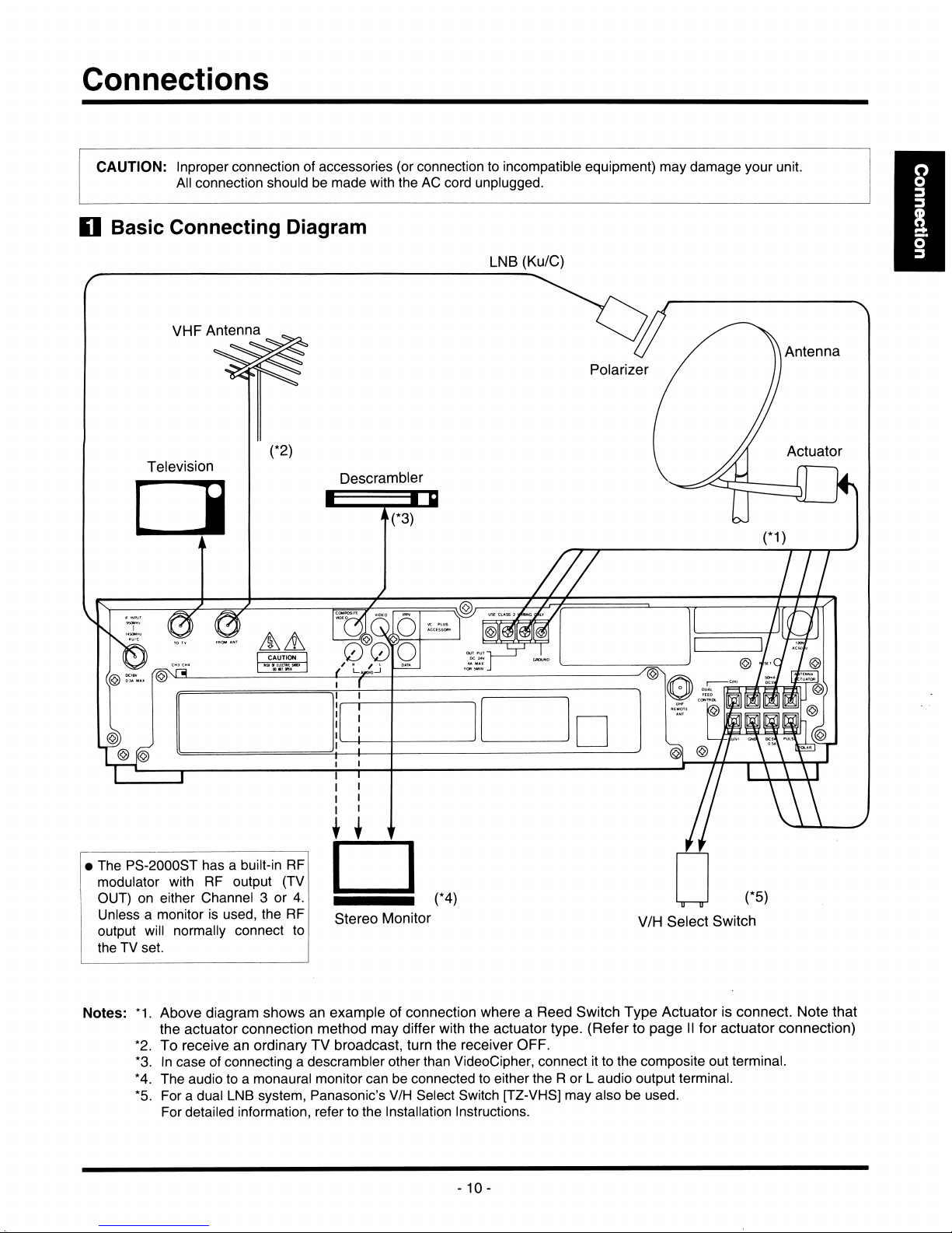
CAUTION:
Inproper
connection
of
accessories
(or
connection
to
incompatible
equipment)
may
damage
your
unit.
All
connection
should
be
made
with
the
AC
cord
unplugged.
Basic
Connecting
Diagram
LNB
(Ku/C)
VHP
Antenna
Antenna
Polarizer
Actuator
Television
Descrambler
■
■ u
AA
CAUTION
•
The
PS-2000ST
has a built-in
RF
modulator
with
RF
output
(TV
OUT)
on
either
Channel 3 or
4.
Unless a monitor
is
used,
the
RF
output
will
normally
connect
to
the
TV
set.
Stereo
Monitor
Ti—r
V/H
Select
Switch
Notes:
*1.
Above
diagram
shows
an
example
of
connection
where a Reed
Switch
Type
Actuator
is
connect.
Note
that
the
actuator
connection
method
may
differ
with
the
actuator
type.
(Refer
to
page
II
for
actuator
connection)
*2.
To
receive
an
ordinary
TV
broadcast,
turn
the
receiver
OFF.
*3.
In
case
of
connecting a descrambler
other
than
VideoCipher,
connect
it
to
the
composite
out
terminal.
*4.
The
audio
to a monaural
monitor
can
be
connected
to
either
the R or L audio
output
terminal.
*5.
For a dual
LNB
system,
Panasonic's
V/H
Select
Switch
[TZ-VHS]
may
also
be
used.
For
detailed
information,
refer
to
the
Installation
Instructions.
-
10-
Connections
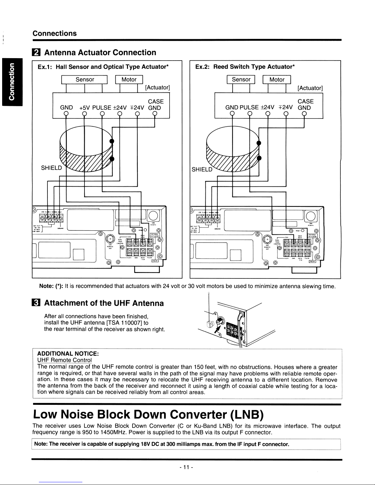
Antenna
Actuator
Connection
Ex.1:
Hall
Sensor
and
Optical
Type
Actuator*
[Actuator'
Sensor
Motor
CASE
GND
+5V
PULSE
±24V
+24V
GND
O
O O O O
SHIELD
Ex.2:
Reed
Switch
Type
Actuator*
Sensor
Motor
[Actuator
CASE
GND
PULSE
±24V
+24V
GND
0
0
0
0
SHIELD
r
Note:
(*):
It
is
recommended
that
actuators
with
24
volt
or
30
volt
motors
be
used
to
minimize
antenna
slewing
time.
Attachment
of
the
UHF
Antenna
After
all
connections
have
been
finished,
install
the
UHF
antenna
[TSA
110007]
to
the
rear
terminal
of
the
receiver
as
shown
right.
ADDITIONAL
NOTICE:
UHF
Remote
Control
The
normal
range
of
the
UHF
remote
control
is
greater
than
150
feet,
with
no
obstructions.
Houses
where a greater
range
is
required,
or
that
have
several
walls
in
the
path
of
the
signal
may
have
problems
with
reliable
remote
oper
ation.
In
these
cases
it
may
be
necessary
to
relocate
the
UHF
receiving
antenna
to a different
location.
Remove
the
antenna
from
the
back
of
the
receiver
and
reconnect
it
using a length
of
coaxial
cable
while
testing
for a loca
tion
where
signals
can
be
received
reliably
from
all
control
areas.
Low
Noise
Block
Down
Converter
(LNB)
The
receiver
uses
Low
Noise
Block
Down
Converter
(0
or
Ku-Band
LNB)
for
its
microwave
interface.
The
output
frequency
range
is
950
to
1450MHz.
Power
is
supplied
to
the
LNB
via
its
output F connector.
Note:
The
receiver
is
capable
of
supplying
18V
DC
at
300
milliamps
max.
from
the
IF
input F connector.
-
11
-
 Loading...