

Panasonic ProLine AG-2570, ProLine AG-2570P Operating Instructions Manual
Operating
Instructions
AG-
/
POWER
PULL-OPEN
EJECT
SEARCH
TIMER REC
STOP
PAUSE/STILL
PLAY
REW
FF
REC/OTR
POCTURE MODE
/I
VQT9139
Video Cassette Recorder
Before attempting to connect, operate or adjust this product,
please read these instructions completely.
2
AUTO CHANNEL SET
PROCEEDING
END : MENU
2
Dear Customer
Thank you for purchasing this Panasonic
Video Cassette Recorder.
We strongly suggest that you carefully study
the Operating Instructions before attempting to
operate the VCR, and that you note the listed
precautions.
ACCESSORIES
1 pc. Remote Controller
1 pc. Coaxial Cable
1 pc. AC Power Cord
2 pcs. “AA” size Batteries
Press [POWER Í/I (VCR Í)] to switch the
VCR from on to standby mode or vice versa.
In standby mode, the VCR is still connected to
the main AC power.
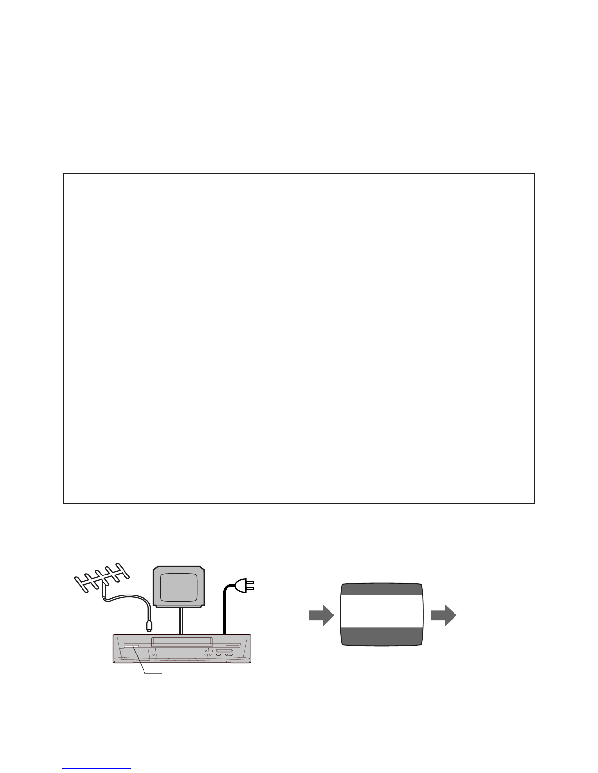
Plug in Auto Tuning
Setting image illustration
Antenna
TV
Connect the
Antenna
cable.
Connect the
AC power
cord.
Press POWER
ÍÍ
ÍÍ
Í/I button.
On Screen display
Plug in Auto
Tuning is
completed.
All broadcasting stations that can be received in the area are automatically tuned and stored in
memory.
– Do not turn off the VCR halfway. (See pages 12–15.)
FCC NOTE:
This equipment has been tested and found
to comply with Part 15 of the FCC Rules.
These limits are designed to provide
reasonable protection against harmful
interference in a residential installation. This
equipment generates, uses and can radiate
radio frequency energy and, if not installed
and used in accordance with the
instructions, may cause harmful
interference to radio communications. If this
equipment does cause or receive
interference, which can be determined by
turning equipment off and on, the user is
encouraged to try to correct the interference
by one of the following measures:
– Reorient or relocate the receiving antenna.
– Increase the separation between the
equipment and receiver.
– Connect the equipment into an outlet on a
circuit different circuit from that to which
the receiver is connected.
– Consult the dealer or an experienced
radio/TV technician for help.
FCC Caution: Any changes or modifications
not expressly approved by the party
responsible for compliance could void the
user’s authority to operate this equipment.
Trade Name: Panasonic
Model No.: AG-2570P
Responsible party:
Matsushita Electric Corporation of America
3330 Cahuenga Blvd. West, Los Angeles,
CA 90068
Support Contact:
Panasonic Broadcast & Television Systems
Company 1-323-436-3500
This device complies with Part 15 of the
FCC Rules. Operation is subject to the
following two conditions:
(1) This device may not cause harmful
interference, and
(2) this device must accept any inteference
received, including interference that may
cause undesired operation.
3
Contents
Before Use
Controls and Connection Sockets .......... 04
Infrared Remote Controller ....................... 06
Remote Controller Setup .......................... 08
Setting Up
Connections ................................................. 09
Tuning the TV to your VCR ........................ 12
– Plug in Auto Tuning ................................. 12
Storing TV Broadcasts in your VCR .......... 14
Language Setting of the On Screen
Display ...................................................... 16
Setting the Clock of your VCR ................... 17
Settings Using the On Screen Display ...... 18
Basic Operations
Playback ....................................................... 22
– Jet Search............................................... 23
– Other Playback Functions...................... 23
Manual Recording ...................................... 25
– One-Touch Recording (OTR) ................ 27
Advanced Operations
Timer Recording ......................................... 28
– 4-Key Programming................................ 28
Search Functions ....................................... 31
– Jet Navigator........................................... 31
– Time Stamp Function.............................. 33
– VHS Index Search System..................... 34
– Intro-Jet Scan ......................................... 34
Editing .......................................................... 35
– Assembly Editing..................................... 35
Other Functions ......................................... 36
– Other Automatic Functions..................... 36
Helpful Hints
Before Requesting Service ....................... 37
Usage Precautions ..................................... 39
Specifications ............................................. 41
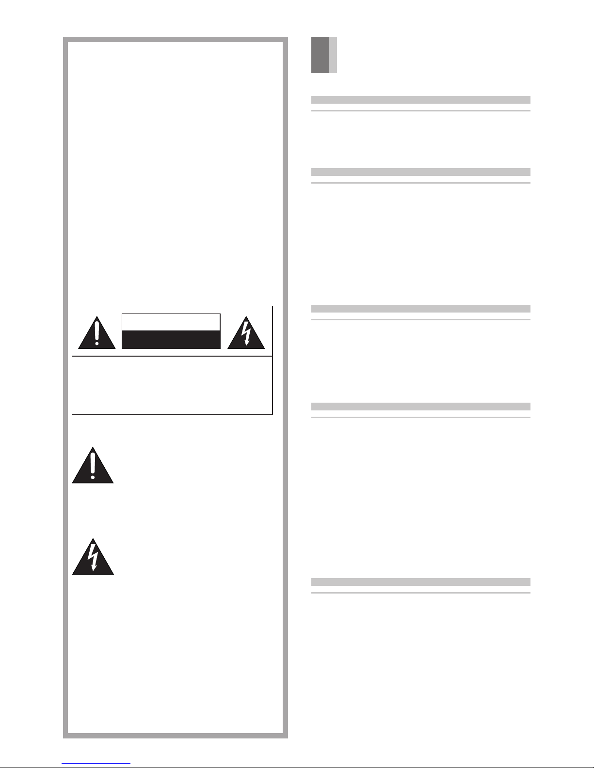
CAUTION
RISK OF ELECTRIC SHOCK
DO NOT OPEN
CAUTION: TO REDUCE THE RISK OF ELECTRIC SHOCK,
DO NOT REMOVE COVER (OR BACK).
NO USER-SERVICEABLE PARTS INSIDE.
REFER SERVICING TO QUALIFIED SERVICE
PERSONNEL.
WARNING
TO REDUCE THE RISK OF FIRE OR
SHOCK HAZARD, DO NOT EXPOSE
THIS EQUIPMENT TO RAIN OR
MOISTURE.
CAUTION:
TO REDUCE THE RISK OF FIRE,
SHOCK HAZARD AND ANNOYING
INTERFERENCE, USE THE
RECOMMENDED ACCESSORIES ONLY.
DO NOT BLOCK ANY OF THE
VENTILATION OPENINGS. INSTALL IN
ACCORDANCE WITH THE
MANUFACTURER’S INSTRUCTIONS.
DO NOT PLACE THIS APPARATUS
INTO AN AUDIO RACK, BOOK SHELF
OR SIMILAR LOCATION BECAUSE OF
HEAT FROM THIS APPARATUS.
This symbol alerts the user that
important literature concerning
the operation and maintenance of
this unit has been included.
Therefore, it should be read
carefully in order to avoid any
problems.
This symbol warns the user that
uninsulated voltages within the
unit may have sufficient
magnitude to cause electric
shock. Therefore, it is dangerous
to make any kind of contact with
any inside part of this unit.
Note to CATV system installer:
This reminder is provided to call the CATV
system installer’s attention to Article 82040 of the NEC that provides guidelines for
proper grounding and, in particular,
specifies that the cable ground shall be
connected to the grounding system of the
building; as close to the point of cable
entry as practical.
4
24
78
6
16 17
5
131211
1 3
9 10
14 15
POWER EJECT
SEARCH
PICTURE MODE
TIMER REC
STOP PLAY
REW FF
PAUSE/STILL
REC/OTR
CVC
RF
OUT
IN
IN (AV1) OUT
VIDEO
AUDIO
R
L
18 19 2024
2321 22
AC IN
SECTEUR
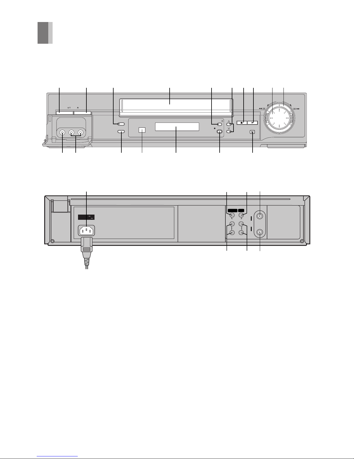
Controls and Connection Sockets
This section describes in detail the function of each button, switch and connection socket.
To mains supply
Before Use
5
FRONT
01 POWER Í/I (VCR Í) (‘ 12)
02 < EJECT (‘ 13)
03 SEARCH (‘ 34)
04 Cassette Compartment (‘ 22)
05 TIMER REC Á (TIMER Á) (‘ 29)0
06 I J (‘ 13, 36)
07 STOP ∫ (‘ 22, 25)
08 PLAY 1 (‘ 22)
09 Jog Dial (‘ 23)
10 Shuttle Ring (‘ 23)
11 VIDEO IN (AV2) (‘ 35)
12 AUDIO IN (AV2) (‘ 35)
13 PICTURE MODE (‘ 19, 24)
14 Infrared Remote Control Receiver
Window
15 Display
16 ¥ REC/OTR (‘ 25, 27)
17 PAUSE/STILL ; (‘ 22)
REAR
18 VIDEO IN (AV1) (‘ 35)
19 VIDEO OUT (‘ 10)
20 RF IN (‘ 9)
21 AUDIO IN (AV1) (‘ 9, 35)
22 AUDIO OUT (‘ 9, 10)
23 RF OUT (‘ 9)
24 AC Input Socket (‘ 9)
TV
VCR
VOLUME
AV
INPUT SELECT
VCR/TV
RESET
OSD/DISPLAY
PICTURE MODE
REC
NAVI
r
W
s
X
W
X
SEARCH
INDEX
OK
AUDIO
∫
1
3
2 1
56
9¥:
Í
Í
;/D
MENU
TIMER
Á
PROG/CHECK SPEED
ON
r
s
OFF
r
s
DATE
r
s
W
X
CANCEL
4
1 2 3 4
1
3
13
8
7
5
6
6
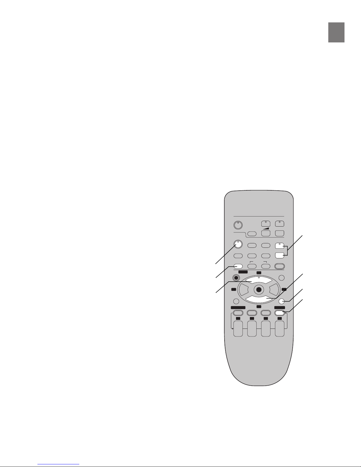
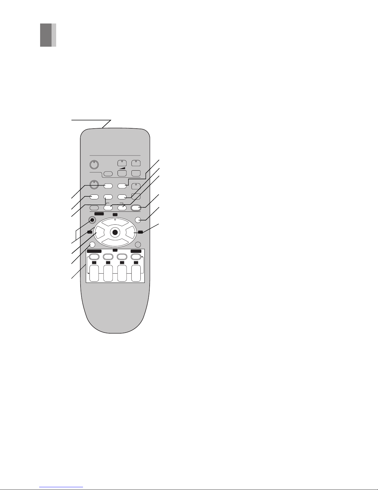
Infrared Remote Controller
The remote control unit for this VCR is a
universal remote controller. As such, some of
its buttons are not used to operate this VCR.
VCR OPERATION
01 Infrared Transmitter
02 INPUT SELECT (‘ 35)
03 OSD/DISPLAY (‘ 18, 26)
14 RESET (‘ 19)
05 On Screen Display Menu Operation
Buttons (‘ 14)
MENU
OK
3421
06 REW (REWIND) 6 (‘ 22)
0
07 ;/D (PAUSE/SLOW) (‘ 22)
08 Timer Recording Operation Buttons
(‘ 28–30)
I J, DATE, ON, OFF
PROG./CHECK
CANCEL
SPEED
TIMER Á
09 VCR/TV (‘ 12)
10 AUDIO (‘ 18)
11 INDEX :, 9 (‘ 34)
12 REC ¥ (‘ 25)
13 NAVI (‘ 31)
14 FF (FAST FORWARD) 5 (‘ 22)
TV
VCR
VOLUME
AV
INPUT SELECT
VCR/TV
RESET
OSD/DISPLAY
PICTURE MODE
REC
NAVI
r
W
s
X
W
X
SEARCH
INDEX
OK
AUDIO
∫
1
3
2 1
56
9¥:
Í
Í
;/D
MENU
TIMER
Á
PROG/CHECK SPEED
ON
r
s
OFF
r
s
DATE
r
s
W
X
CANCEL
4
1 2 3 4
1
2
3
4
6
8
7
5
10
9
11
12
13
14
Before Use
7
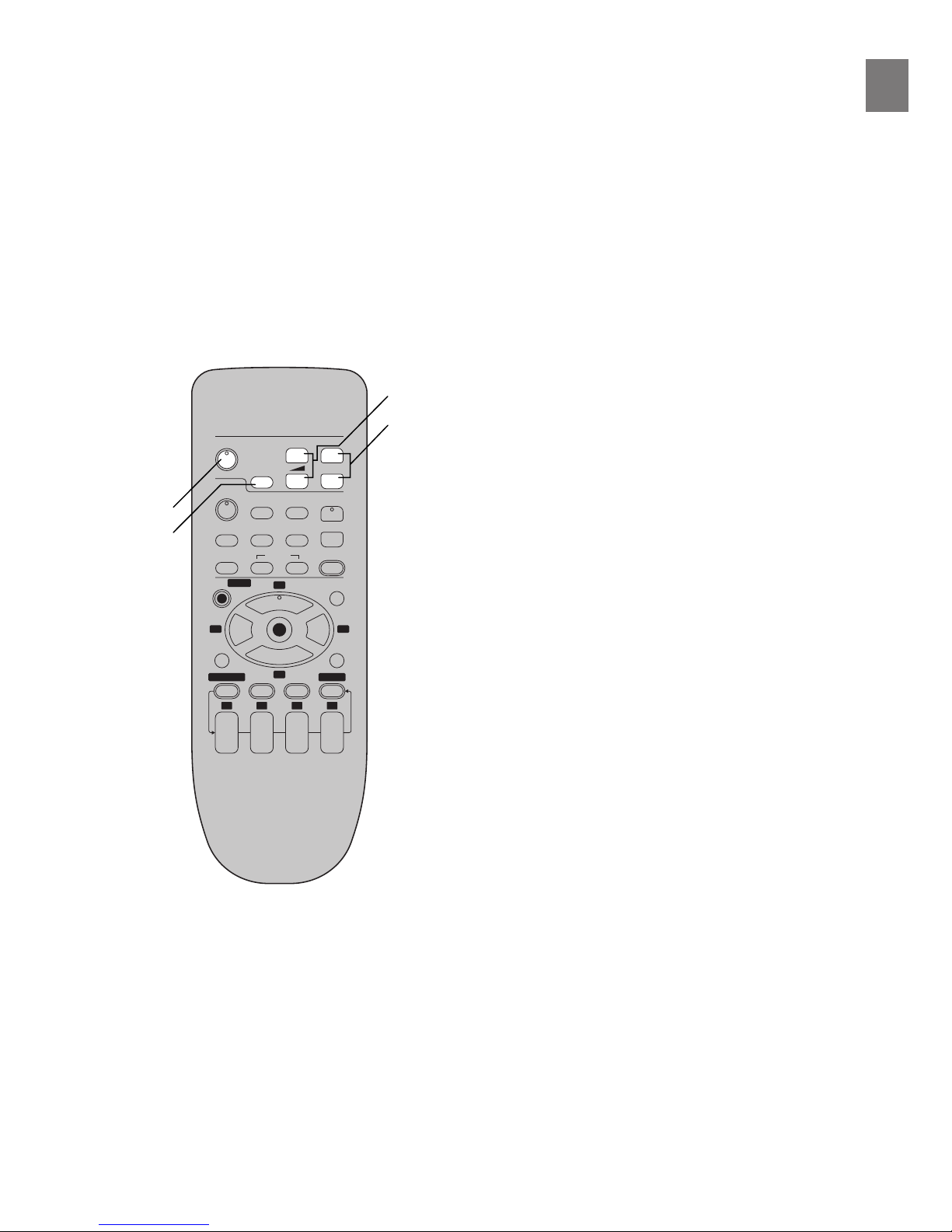
13 TV Í
Press to switch the TV from on to standby
mode or vice versa. In standby mode, the
TV is still connected to the mains.
– With some TV models, it may only be
possible to switch the TV to the standby
mode using this button.
In this case, use [AV] or the I and J
buttons to switch the TV on.
– Ensure that [VCR/TV] switch is set to
[TV].
14 AV
Selects TV input or AV input.
15 VOLUME sNr
Adjusts the volume of the TV.
16 I J
Selects the required program position (TV
station) of the TV.
– Ensure that [VCR/TV] switch is set to
[TV].
TV
VCR
VOLUME
AV
INPUT SELECT
VCR/TV
RESET
OSD/DISPLAY
PICTURE MODE
REC
TIMER
Á
NAVI
PROG/CHECK SPEED
ON
r
s
OFF
r
s
DATE
r
r
s
W
W
X
s
X
W
X
SEARCH
CANCEL
INDEX
OK
AUDIO
∫
1
3
4
2 1
56
9¥:
Í
Í
;/D
MENU
1 2 3 4
13
15
14
16
TV OPERATION
Only Panasonic TVs can be operated with the
provided remote control. The settings for
operating the TV with the remote control have
already been made.
No additional settings need to be performed.
However, some Panasonic TVs cannot be
operated using this remote control.
8
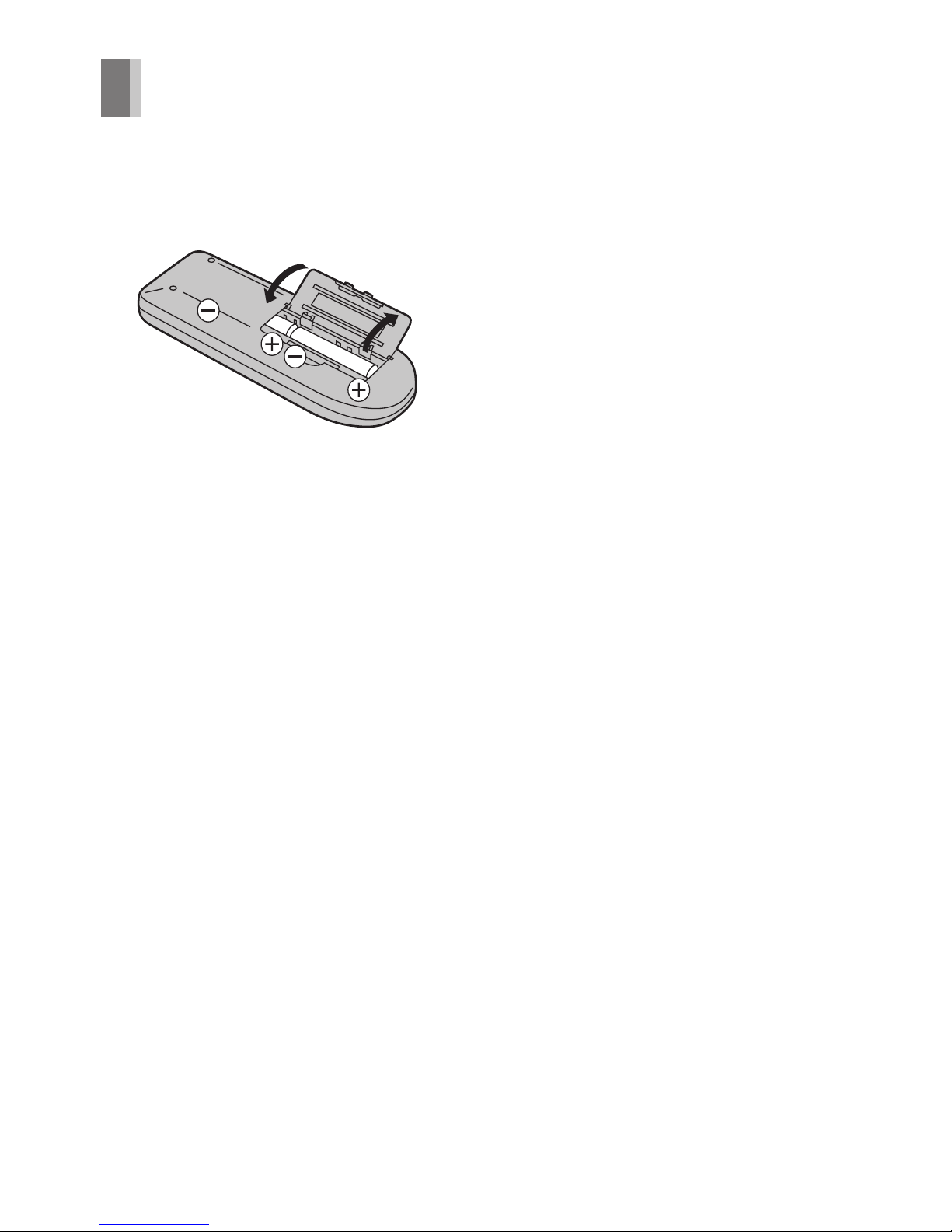
Remote Controller Setup
Installing the Batteries
Insert the batteries with the polarity (+ and -)
correctly aligned.
Power Source for the Remote Controller:
The remote controller is powered by 2 AA, UM3
or R6 size batteries. The life of the batteries is
about one year, although this depends on the
frequency of use.
Precautions for Battery Replacement:
– Load the new batteries with their polarity (+
and -) aligned correctly.
– Do not apply heat to the batteries, or an
internal short circuit may occur.
– If you do not intend to use the remote
controller for a long period of time, remove
the batteries and store them in a cool and dry
place.
– Remove spent batteries immediately and
dispose of them.
– Do not use an old and a new battery together,
and never use an alkaline battery with a
manganese battery.
– Do not use rechargeable batteries.
9
Setting Up
RF
OUT
IN
IN (AV1) OUT
VIDEO
AUDIO
R
L
3
1
2
AC IN
SECTEUR
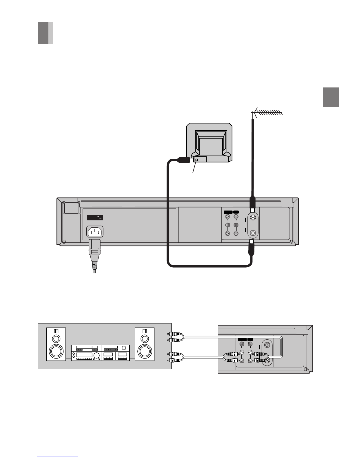
Connections
This section shows you how to connect the
VCR to an antenna, TV, etc.
When the VCR is turned on after connecting
the antenna cable and the AC power cord,
Plug in Auto Tuning starts automatically.
Basic Connections
The following connections are required to
record and play back the video cassette
through the TV.
TV Set (Not supplied)
Antenna (Not supplied)
Antenna Input Connector
To mains supply
Connection to a Stereo Amplifier
RF
OUT
IN
IN (AV1) OUT
VIDEO
AUDIO
R
L
Stereo Amplifier
(Not supplied)
PLAYBACK
(Not supplied)
REC
10
RF
OUT
IN
IN (AV1) OUT
VIDEO
AUDIO
R
L
4
3
1
2
AC IN
SECTEUR
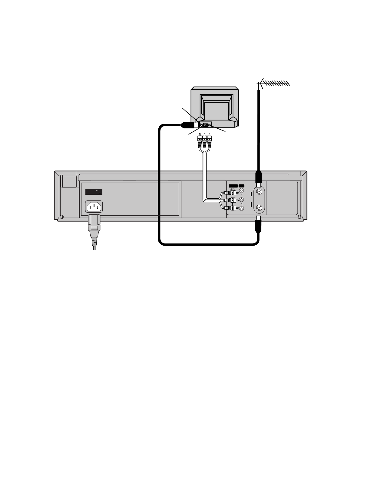
Connection to a TV using the Audio/Video Input Sockets
Antenna Input
Connector
TV Set (Not supplied)
Antenna (Not supplied)
VIDEO IN
AUDIO IN
(Not supplied)
To mains supply
11
Setting Up
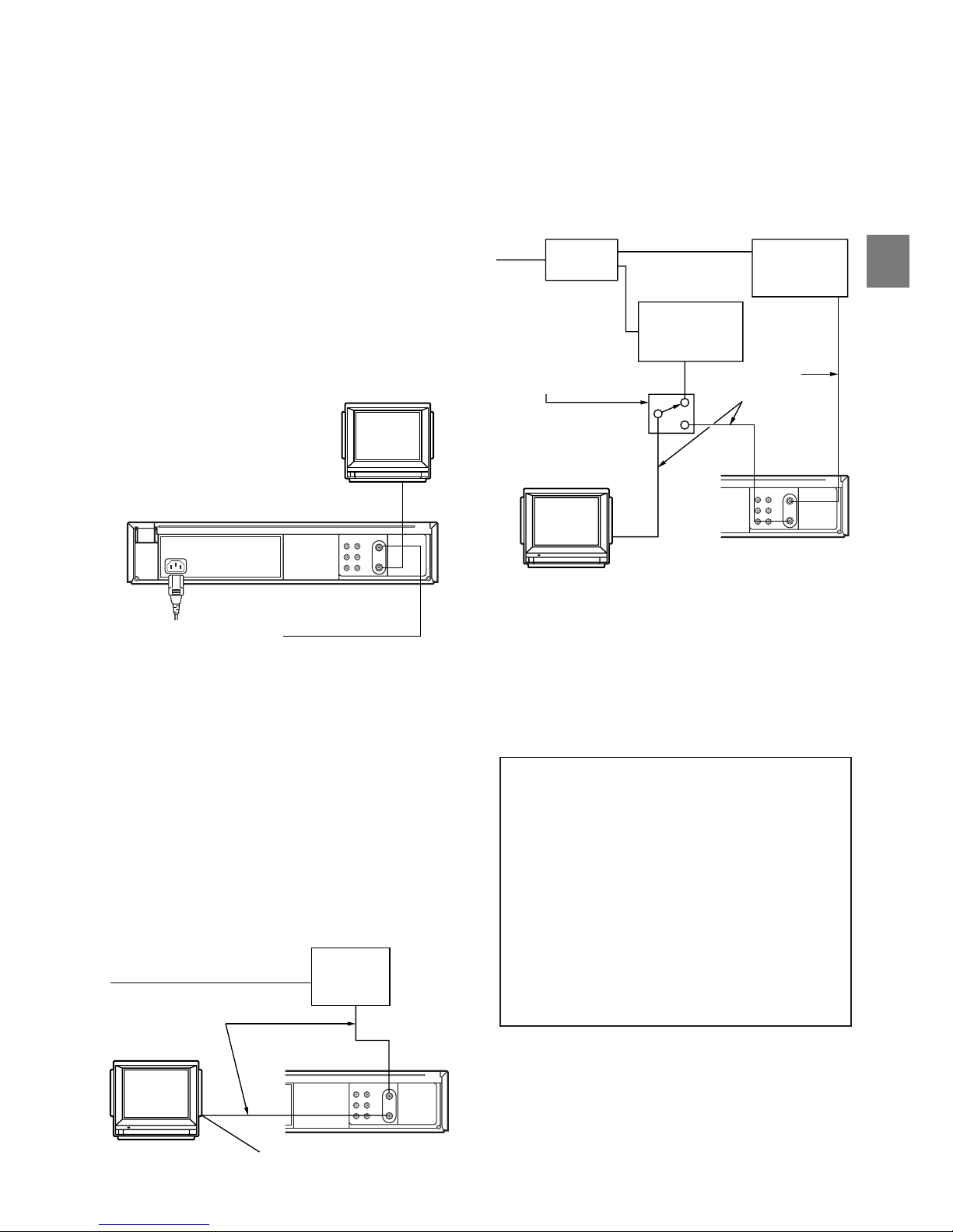
Cable Connection
Cable-VCR-TV (For CATV/PAY
Channels Recording/Playback)
The VCR has an extended range, and can
tune the Low-Band, Mid-Band, Super-Band,
Hyper-Band, Ultra-Band, and Special cable
channels (Channels A-5–A-1, A–W, AA–FFF,
GGG–WWW, WWWr1–WWWr12, 100–125,
5A). Also, the VCR can tune to any of the 56
UHF channels (14– 69). Refer to Storing TV
Broadcasts in your VCR on page 15.
BASIC Hook-Up
Since the VCR can tune Mid
and Super Bands, this
connection will provide the
reception of all cable channels
except those which are
intentionally scrambled.
75 ohm Coaxial Cable
However, if you subscribe to a special channel
which is scrambled you will probably have a
descrambler box for proper reception. The VCR
by itself cannot properly receive a scrambled
program since it does not contain a
descrambler. In order for the VCR to properly
receive a scrambled program, your existing
descrambler must be used. There are two
commonly used methods of connection in this
case.
Typical Cable System Hook Ups
with Cable Converter/Descrambler
Boxes
The cable hook-up shown at the bottom left
allows VCR-TV functions except for viewing
one channel while recording another.
The above cable hook-up allows VCR
functions, including viewing one channel while
recording another, but it requires two cable TV
Converter/Descrambler Boxes, one Switch Box
and one 2-Way Splitter.
Since the VCR has an extended range of
tuning, tuning-programing of non-scrambled
Mid-Band and Super-Band TV programs is
possible. When a cable converter or
descrambler box is connected to the VCR,
all timer-controlled recording functions will
continue to operate with the exception of
charging channels automatically. CATV
Channel selection will have to be performed
with the cable converter. Timer-controlled
recording from CATV Channels is therefore
limited to one channel at any given time.
75 ohm Cable System
75 ohm Coaxial
Cables
Cable TV
Converter
BoxIN
OUT
To the 75 ohm VHF
Input on the TV set
75 ohm Cables System
IN
2-WAY
SPLITTER
OUT1 IN
Cable TV
Converter Box
OUT2
IN
Cable TV
Converter Box
OUT
Switch Box°
OUT
75 ohm Coaxial
Cables
°Not available from
our company.
Please contact your
cable company.
To the 75 ohm VHF
Input on the TV set
12
TV
VCR
VOLUME
AV
INPUT SELECT
VCR/TV
RESET
OSD/DISPLAY
PICTURE MODE
REC
TIMER
Á
NAVI
PROG/CHECK SPEED
ON
r
s
OFF
r
s
DATE
r
r
s
W
W
X
s
X
W
X
SEARCH
CANCEL
INDEX
OK
AUDIO
∫
1
3
4
2 1
56
9¥:
Í
Í
;/D
MENU
1 2 3 4
21
RF
OUT
IN
(AV1) OUT
VIDEO
AUDIO
R
L
3
1
AUTO CHANNEL SET
PROCEEDING
END : MENU
2
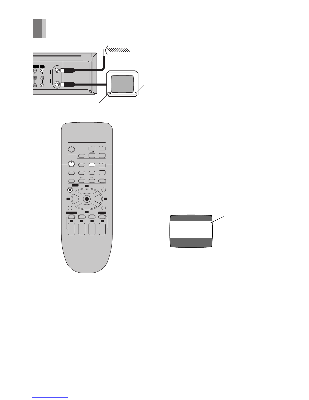
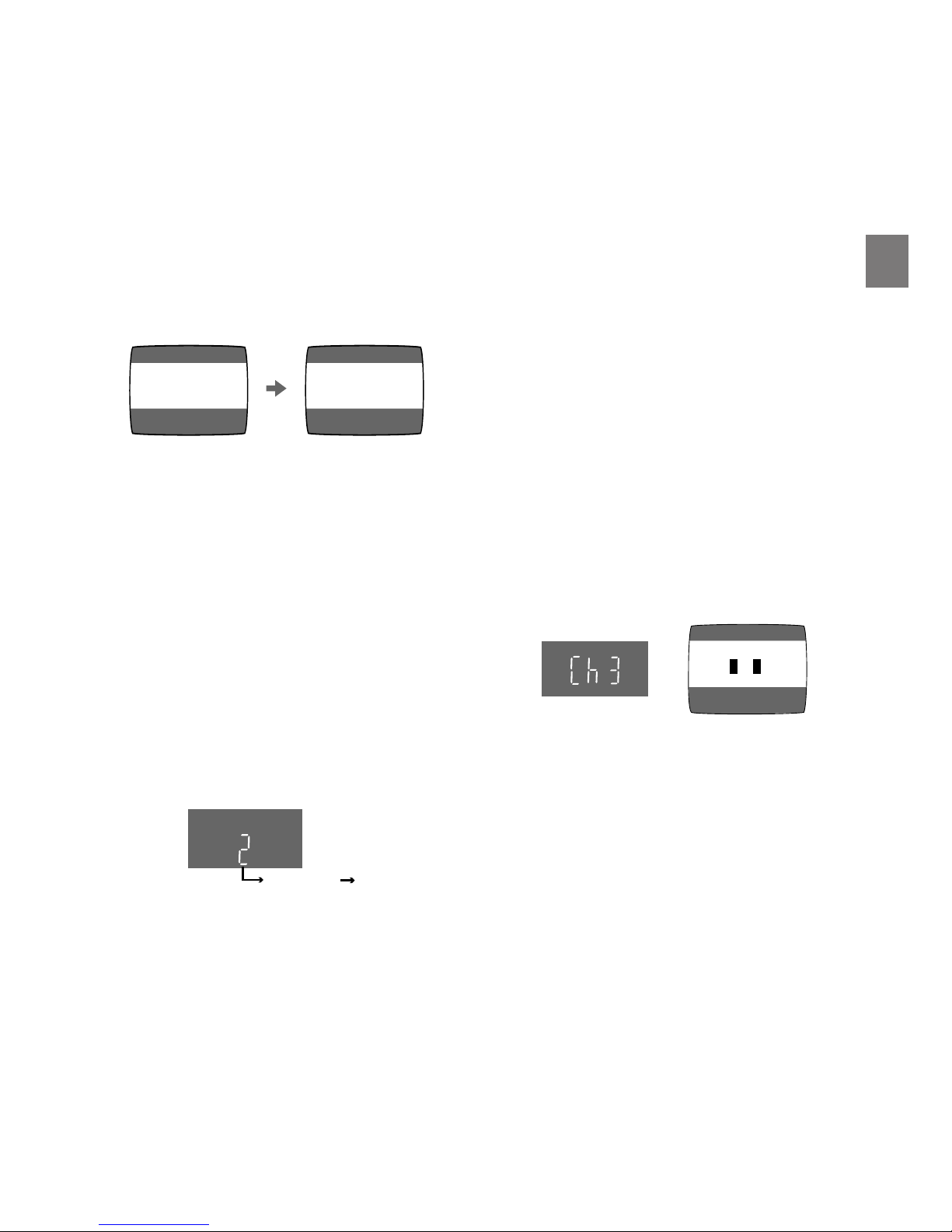
Tuning the TV to your VCR
The VCR supplies a signal to the TV via the RF
coaxial cable on channel US3 or 4.
It is possible to view the video picture on your
TV in the same way that you watch TV
broadcasts.
If you have connected the VCR to the TV
through the video and audio input sockets, then
you do not need to follow the procedure below.
When the VCR is turned on after unpacking
and connecting the antenna cable and the
AC power cord, Plug in Auto Tuning starts
automatically.
The VCR is fitted with its own tuner (just like a
normal TV) and can be preset to receive up to
181 TV broadcast stations.
Plug in Auto Tuning
Auto Tuning searches for TV stations from VHF
minimum to UHF maximum and memorizes
every tuned program position.
Notes:
– If the VCR is turned on with the antenna not
connected, all channels are skipped.
– When Auto Tuning is canceled halfway, Auto
Tuning is not executed even if the VCR is
turned off and then turned on again. In this
case, see page 13 “To Restart Plug in Auto
Tuning”.
1 Press [POWER Í/I (VCR Í)] to turn on the
TV and VCR after connecting the antenna
cable and the AC power cord, Auto Tuning
starts.
Channel being
searched
– Auto Tuning will stop halfway by turning
the VCR off, pressing [MENU], playback
or a power failure during Auto Tuning.
– When there are 5 more CATV channels,
the antenna system CATV is automatically
selected; when there are 4 or fewer CATV
channels, the TV is selected. If a change is
required, conduct the resetting procedure
described in step 4 on page 14.
2 Press [VCR/TV] to select the VCR mode.
13
Setting Up
AUTO CHANNEL SET
PROCEEDING
END : MENU
2
AUTO TUNING IS
COMPLETED.
END: MENU
Disappears 2
3 Select a program number on the TV which
you wish to use as the video viewing
channel. Then tune in the TV to the picture
from the screen being auto tuned or the
screen selected with the I and J buttons
of the VCR.
– During Auto Tuning, the TV program
screen does not appear, and the Auto
Tuning screen appears instead.
To Cancel Auto Tuning MidOperation
Press [MENU] during Auto Tuning. Auto Tuning
is cancelled.
To Restart Plug in Auto Tuning
1 Press [EJECT] and remove the video
cassette.
2 Keep the I and J buttons on the VCR
pressed simultaneously for 3 seconds or
more during the VCR on.
– The channel displayed on the VCR display
disappears for a moment then changes to
2.
3 Disconnect the mains lead and then
reconnect it.
4 Turn off the VCR and then turn it on.
Press [VCR/TV] to select the VCR mode.
– Auto Tuning commences.
If Auto Tuning stops halfway by turning the
VCR off, playback or a power failure:
1 Disconnect the mains lead and then
reconnect it.
2 Turn off the VCR and then turn it on.
– Auto Tuning commences.
To Change the RF Output
Channel
In some rare cases after tuning the TV to your
VCR, interference may be visible on the
picture. To get rid of this interference, you can
manually adjust the RF output channel a few
channels up and down from the current setting.
The procedure is described below.
1 Hold down [MENU] for 5 seconds or more.
– The VCR display changes as shown below
and the VCR picture on the TV displays
this pattern.
2 Enter the desired channel number (US3 or
US4) by the I and J buttons.
3()4
3 Press [MENU] to finish the setting mode.
4 Retune your TV to the new RF channel for
the VCR.
Note:
– Even if the RF output channel has been
changed, it is not necessary to perform Auto
Tuning.
Panasonic VCR
END: MENU
14
TV
VCR
VOLUME
AV
INPUT SELECT
VCR/TV
RESET
OSD/DISPLAY
PICTURE MODE
REC
TIMER
Á
NAVI
PROG/CHECK SPEED
ON
r
s
OFF
r
s
DATE
r
r
s
W
W
X
s
X
W
X
SEARCH
CANCEL
INDEX
OK
AUDIO
∫
1
3
4
2 1
56
9¥:
Í
Í
;/D
MENU
1 2 3 4
Storing TV Broadcasts in your VCR
Auto Tuning Using the On
Screen Display
The VCR is tuned automatically by Plug in Auto
Tuning. However, Auto Tuning using the On
Screen Display should be performed according
to the following method if necessary.
Notes:
– Auto Tuning searches for TV stations from
VHF minimum to UHF maximum and
memorizes every tuned program position.
Other program positions are skipped.
– Auto Tuning takes three or more minutes to
complete its search.
– If the VCR is not correctly tuned by Auto
Tuning, follow the procedure on the next
page.
Preparations
– Confirm that the TV is on and the VCR
viewing channel is selected.
– Turn on the VCR and select any program
position except AV input.
– Press [VCR/TV] to select the VCR mode.
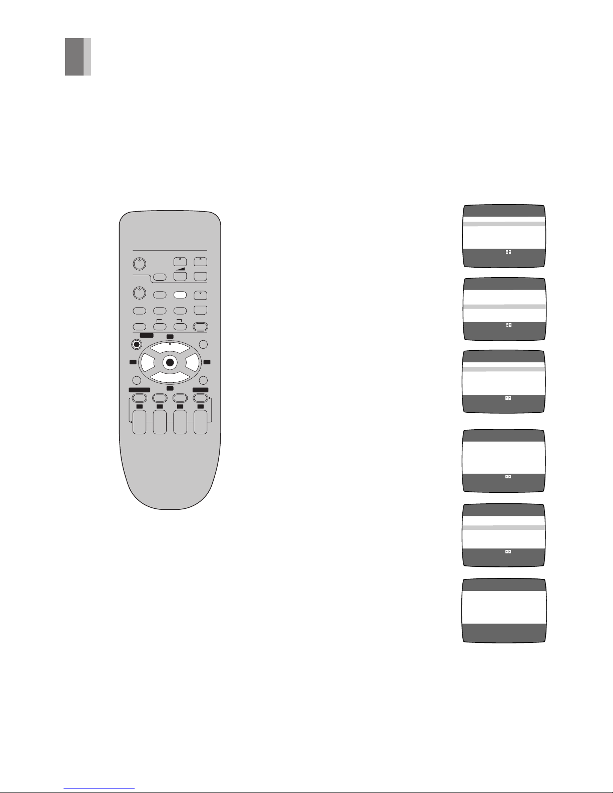
Operations
1 Press [MENU].
2 Select [CHANNEL SET]
by pressing 3 or 4 and
then press [OK].
3 Select [ANTENNA
SYSTEM] by pressing
3 or 4 and then press
[OK].
4 Select the desired
system by pressing 3 or
4 and then press
[MENU].
5 Select [AUTO] by
pressing 3 or 4 and
then press [OK].
– When Auto Tuning is
completed, the on
screen display
disappears and the
lowest channel position
at which a broadcast
can be tuned in is
received.
AUTO CHANNEL SET
PROCEEDING
END :MENU
2
LANGUAGE
CLOCK SET
≥CHANNEL SET
SELECT
END
: , OK
:MENU
OSD MENU
OPTION
SELECT
END
:
:MENU
CATV
ANTENNA SYSTEM
≥TV
≥AUTO
SELECT
END
: , OK
:MENU
CHANNEL SET
ANTENNA SYSTEM
MANUAL
≥LANGUAGE
SELECT
END
: , OK
:MENU
OSD MENU
CLOCK SET
CHANNEL SET
OPTION
SELECT
END
: , OK
:MENU
CHANNEL SET
≥ANTENNA SYSTEM
AUTO
MANUAL
 Loading...