

Page 1
81-IN3036.9923Manufactured by:
for
Before attempting to connect or operate this product,
please read these instructions completely.
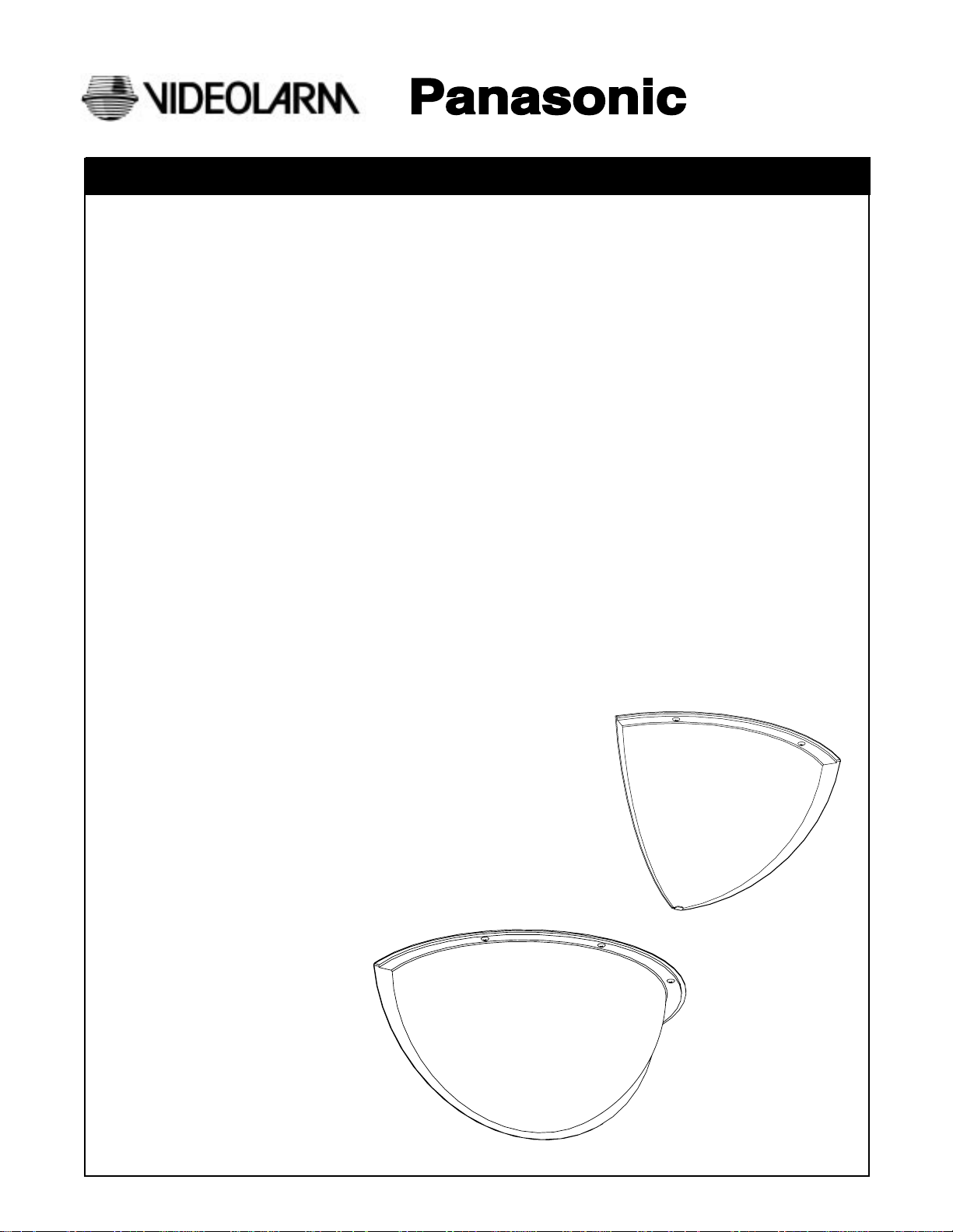
INDOOR DOMED HOUSINGS
Quarter/Half Dome Housing
Models Include: PQD8, PHD8
DESCRIPTION:
Fully discrete indoor domed housing. Low profile wall or corner mount well-suited for office, hallway, and conference room use.
FEATURES:
• Dome formed from high-impact, tinted, cell-cast acrylic
• Mounting frame constructed from 18-gauge steel
• Comes complete with fully adjustable 12-gauge steel camera bracket
• Tinted acrylic causes approximately 1.5 F-stop light loss
• Can be mounted at any height on wall
• Can be mounted at any height on corner
• Complete with gold or silver accent trim
• Max. storage space is 8"
(Panasonic 1/3" Camera Class with Panasonic Fixed Focal Lens Series.)
Installation and
Operating Instructions
Page 2
1. Read Instructions - All the safety and operating instructions
!
should be read before the unit is operated.
2. Retain Instructions - The safety and operating instructions
should be retained for future reference.
3. Heed Warnings - All warnings on the unit and in the operating
instructions should be adhered to.
4. Follow Instructions - All operating and user instructions should
be followed.
5. Electrical Connections - Only a qualified electrician should
make electrical connections.
6. Attachments - Do not use attachments not recommended by the
product manufacturer as they may cause hazards.
7. Cable Runs - All cable runs must be within permissible distance.
8. Mounting - This unit must be properly and securely mounted to
a supporting structure capable of sustaining the weight of the
unit. Accordingly:
a. The installation should be made by a qualified service
person, and should conform to all local codes.
b. Care should be exercised to select suitable hardware to
install the unit, taking into account both the composition of the
mounting surface and the weight of the unit. Be sure to
periodically examine the unit and the supporting structure to
make sure that the integrity of the installation is intact. Failure
to comply with the foregoing could result in the unit separating
from the support structure and falling, with resultant damages
or injury to anyone or anything struck by the falling unit.
SAFETY PRECAUTIONSIMPORTANT SAFEGUARDS
CAUTION
RISK OF
ELECTRIC SHOCK!
CAUTION: TO REDUCE THE RISK OF
ELECTRICAL SHOCK, DO NOT EXPOSE
COMPONENTS TO WATER OR MOISTURE.
The lightning flash with an arrowhead symbol,
within an equilateral triangle, is intended to
alert the user to the presence of non-insulated
"dangerous voltage" within the product's
enclosure that may be of sufficient magnitude
to constitute a risk of electric shock to persons.
The exclamation point within an equilateral
triangle is intended to alert the user to
!
UNPACKING
Unpack carefully. Electronic components can be
damaged if improperly handled or dropped. If an item
appears to have been damaged in shipment, replace it
properly in its carton and notify the shipper.
presence of important operating and
maintenance (servicing) instructions in the
literature accompanying the appliance.
Be sure to save:
1. The shipping carton and packaging material. They are the
safest material in which to make future shipments of the
equipment.
2. These Installation and Operating Instructions.
SERVICE
For service on Panasonic/Videolarm equipment contact:
Panasonic Technical Center
54 West Gude Dr.
Rockville MD 20850-1150
Phone: 301-762-5125
Fax: 301-251-0347
PANASONIC TECHNICAL SUPPORT
1-800-528-6747
9:00 AM - 5:00 PM EASTERN TIME
- 2 -
Page 3

Half Dome Housing - PHD8
PHD8 Dome
PHD8 Housing
Trim-ring
General Instructions:
Use only with Class 2 Power Supply
!
Top knockout
A PHD8 Housing
Note: Mounting hardware for housing is not supplied.
1. Carefully remove all equipment from the box.
2. If housing is to be mounted against ceiling, remove top
knock-out from the PHD8 housing (A). If housing is to be
mounted against a wall but not against the ceiling,
remove side knock-out from the PHD8 housing (See Fig. 1).
3. Use the knock-out to mark the hole to be drilled into the
wall or ceiling. Carefully drill the marked hole and replace
housing to the appropriate spot.
4. Using the (4) four mounting holes in the housing, secure the
housing to a sturdy wall making sure housing surfaces are
flush with the walls (See Fig. 1).
5. To attach a camera with a maximum camera length of (8)
six inches:
For steep viewing angles; attach FM3 Bracket (C) to the
housing as shown in (Fig. 2) using (1) one 1/4" SAE Flat
washer (H), (1) one 1/4" SAE Split lock-washer (I) and (1)
one 1/4" Hex nut (J). Next, attach the M7 Camera Bracket
(D) and camera to FM3 Bracket using (1) one 3/8" SAE Flat
washer (G) and (1) one 1/4" SAE Flat washer (H), (1) one 1/
4" Split lock-washer (I), (1) one 1/4-20 x 1/2" Hex head bolt
(F) (Fig. 2). Adjust the camera to the desired angle,
making sure the fasteners are secure, but not fully tightened. Connect the cable to the camera.
Side knockout
FIG. 1
D M7 Camera
bracket
G 3/8" SAE flat
washer
C FM3 Bracket
H 3/8" SAE flat
washer
I 1/4" Split lock-washer
FIG. 2
* NOTE: All parts listing
is same as Fig. 2
(FM3 Bracket is
positioned differently).
Mounting
holes
T 1/4-20 Hex nut
F 1/4-20 x 1/2" Hex head bolt
For level viewing angles; attach FM3 Bracket (C) to the
housing as shown in (Fig. 3) using (1) one 1/4" SAE Flat
washer (H), (1) one 1/4" SAE Split lock-washer (I) and (1)
one 1/4" Hex nut (J). Next, attach M7 Camera Bracket (D)
and camera to FM3 Bracket using (1) one 3/4" SAE Flat
washer (G) and (1) one 1/4" SAE Flat washer (H), (1) one 1/
4" Split lock-washer (I), (1) one 1/4-20 x 1/2" Hex head bolt
(F) (See Fig. 3). Adjust the camera to the desired angle,
making sure the fasteners are secure, but not fully tightened. Connect the cable to the camera.
6. Place the PHD8 Dome (B) in the housing so the flange of
the dome is flush with the underside of the housing. Be sure
that the camera is not touching the dome (See Fig. 4).
7. Remove the PHD8 Dome and tighten all camera and
bracket fasteners.
8. Using the (3) three 8-32 screws (E), fasten the PHD8 Dome
to the PHD8 Housing. Be sure to fasten one side screw first,
then the center screw. Hole may not be centered over the
second side insert. If not, place screw in hole with a
screwdriver and use screwdriver to pull flange outwards to
fasten the the last side screw.
9. (Optional installation of trim-ring):
Press the open end of the trim-ring onto the top corner
edge of the housing so that the housing edge slides into
the trim-ring groove. Press the trim-ring along the radius of
the top until edge is covered and trim-ring is secure.
FIG. 3
FIG. 4
FIG. 5
Dome flange
B PHD8 Dome
A PHD8 Housing
E Phillips screws
- 3 -
Page 4

Quarter Dome Housing - PQD8
General Instructions:
Use only with Class 2 Power Supply
!
Note: Mounting hardware for housing is not supplied.
1. Carefully remove all equipment from the box.
2. If housing is to be mounted against ceiling, remove top
knock-out from the PQD8 Housing (A). If housing is to be
mounted in corner but not against the ceiling, remove
side knock-out from the PQD8 Housing (See Fig. 1).
3. Use the knock-out to mark the hole to be drilled into the
wall or ceiling. Carefully drill the marked hole and replace
housing to appropriate spot.
4. Using the (4) four mounting holes in the PQD8 Housing,
secure the housing to a sturdy corner, making sure housing
surfaces are flush with the walls (See Fig. 1).
5. Using the PQD8 Camera Bracket (C) in the housing, attach
a camera with a maximum camera length of (8) six inches
using the 1/4-20x1/2" Hex head bolt (E), 1/4 Split lockwasher (G), provided. Adjust the Camera Bracket to the
desired angle, making sure the fasteners are secure, but
not fully tightened. Complete all electrical connections
with the camera.
6. Place the PQD8 Dome (B) in the housing so the flange of
the dome is flush with the underside of the housing. Be sure
that the camera is not touching the dome (See Fig. 2).
7. Remove the PQD8 Dome and tighten all camera and
bracket fasteners.
8. Using the (2) two 8-32 screws (D), fasten the PQD8 Dome
to the PQD8 Housing. Make sure the corner of the dome is
inside the bottom tab of housing (See Fig. 2).
9. (Optional installation of trim-ring):
Press the open end of the trim-ring onto the top corner
edge of the housing so that the housing edge slides into
the trim-ring groove. Press the trim-ring along the radius of
the top until edge is covered and trim-ring is secure.
FIG. 1
A PQD8 Housing
FIG. 2
FIG. 3
Top knockout
Mounting
holes
Housing tab
PQD8 Dome
D Philips screws
A PQD8 Housing
Side knockout
Dome flange
B PQD8 Dome
Trim-ring
PQD8 Housing
- 4 -
Page 5

H 1/4" SAE Flat washer
A PHD8Housing
C FM3 Bracket
G 3/8" SAE Flat washer
H 1/4" SAE Flat washer
I 1/4" Split lock-washer
F 1/4-20 x 1/2" Hex head bolt
E 8-32 x 1/4’ Phillips screws
J 1/4-20 Hex nut
Description Part number Qty.
A PHD8 Housing 30-VL1455 1
B PHD8 Dome 20-DTHD7 1
C FM3 Bracket 30-VL1463 1
D M7 Camera bracket 23-SWBL01 1
E 8-32x1/4" Philips screws 90-BTTP01 3
F 1/4-20x1/2" Hex head bolt 90-BTHH32 1
G 3/8" SAE Flat washer 92-WSFL04 1
H 1/4" SAE Flat washer 92-WSFL01 2
I 1/4" Split lock-washer 92-WSSL01 2
J 1/4-20 Hex nut 91-NTHH02 1
k Chrome trim-ring 96-TRLK08 1
L Gold trim-ring 96-TRLK07 1
K Chrome trim-ring/
L Gold trim-ring
D M7 Camera bracket
A PQD8 Housing
E 1/4-20 x 1/2" Hex head bolt
G 1/4" Split lock-washer
F 1/4" SAE Flat washer
B PQD8 Dome
Description Part number Qty.
A PQD8 Housing 30-VL1454 1
B PQD8 Dome 20-DTQD8 1
C PQD8 Camera bracket 30-VL1464 1
D 8-32x1/4" Philips screws 90-BTTP01 2
E 1/4-20x1/2" Hex head bolt 90-BTHH32 1
F 1/4" SAE Flat washer 92-WSFL01 2
G 1/4" Split lock-washer 92-WSSL01 2
H 1/4-20x1/2" Hex head bolt 90-BTHH32 2
I O-ring 96-RSORNG 1
J Chrome trim-ring 96-TRLK08 1
K Gold trim-ring 96-TRLK07 1
J Chrome trim-ring/ K Gold trim-ring
H 1/4-20 x 1/2" Hex head bolt
C PQD8 Camera bracket
I O-ring
D 8-32 x 1/4" Phillips screws
- 5 -
 Loading...