

Page 1

Manufactured by:
for
Before attempting to connect or operate this product, please
read these instructions completely.
OUTDOOR ENVIRONMENTAL HOUSING
ALUMINUM PRESSURIZED HOUSING
Models Include: PPH14
DESCRIPTION: The PPH14 housings are environmental sealed and
pressurized camera enclosures designed to protect CCTV
cameras from harsh environments. The housings are
designed to accomodate CCD cameras with fixed focal
length lenses or motorized zoom lenses with maximum
camera length of 14".
81-IN3038.9923
FEATURES: • Constructed of seamless aluminum tubing
• Equipped with an adjustable mounting bracket and
slide-out camera platform
• Front window made of tempered glass for distortion free viewing
• Completely sealed to eliminate dust and moisture
problems
• Supplied with thermostatically controlled heaters
Installation and
Operating Instructions
SECURITY PRODUCTS WELL DESIGNED FOR PERFORMANCE, FLEXIBILITY & STYLE
Page 2
IMPORTANT SAFEGUARDS
1. Read Instructions - All the safety and operating instructions
should be read before the unit is operated.
2. Retain instructions - The safety and operating instructions
should be retained for future reference.
3. Heed Warnings - All warnings on the unit and in the operat
ing instructions should be adhered to.
4. Follow Instructions - All operating and user instructions should
be followed.
5. Electrical Connections - Only a qualified electrician should
make electrical connections.
6. Attachments - Do not use attachments not recommended
by the product manufacturer as they may cause hazards.
7. Cable Runs - All cable runs must be within permissible
distance. (See cable run chart in these instructions.)
8. Mounting - This unit must be properly and securely mounted
to a supporting structure capable of sustaining the weight of
the unit. Accordingly,
a. The installation should be made by a qualified installer.
b. The installation should be in compliance with local
codes.
c. Care should be exercised to select suitable hardware
to install the unit, taking into account both the com
position of the mounting surface and the weight of
the unit. Be sure to periodically examine the unit and
the supporting structure to make sure that the integrity
of the installation is intact.
Failure to comply with the foregoing could result in the unit
separating from the support structure and falling, with
resultant damages or injury to anyone or anything struck by
the falling unit.
SAFETY PRECAUTIONS
CAUTION
RISK OF ELECTRIC
SHOCK!
CAUTION: TO REDUCE THE RISK OF
ELECTRICAL SHOCK, DO NOT EXPOSE
THE UNIT TO WATER OR MOISTURE.
The lightning flash with an arrowhead
symbol, within an equilateral triangle, is
intended to alert the user to the presence
of non-insulated " dangerous voltage"
within the product's enclosure that may be
of sufficient magnitude to constitute a risk
of electric shock to persons.
The exclamation point within an equilateral
triangle is intended to alert the user to
presence of important operating and
maintenance (servicing) instructions in the
literature accompanying the appliance.
UNPACKING
Unpack carefully. Electronic components can be damaged if
improperly handled or dropped.
If an item appears to have been damaged in shipment, replace
it properly in its carton and notify the shipper.
Be sure to save:
1. The shipping carton and packaging material. They are the
safest material in which to make future shipments of the
equipment.
2. These Installation and Operating Instructions.
SERVICE
For service on Panasonic/Videolarm equipment cantact:
Panasonic Technical Center
54 West Gude Dr.
Rockville MD 20850-1150
Phone: 301-762-5125
Fax: 301-251-0347
PANASONIC TECHNICAL SUPPORT
1-800-528-6747
9:00 AM - 5:00 PM EASTERN TIME
- 2 -
Page 3
1.0 INSTALLATION PROCEDURE
Pin # Function
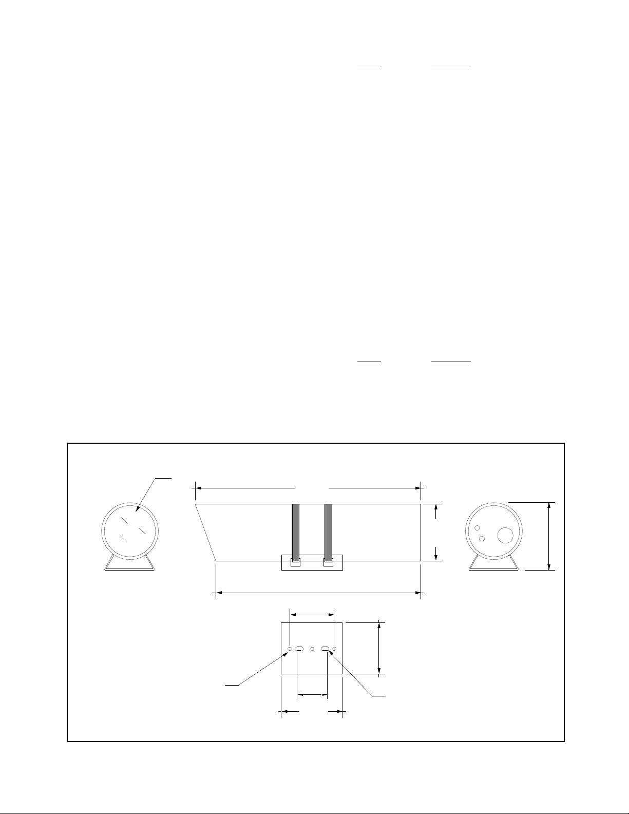
1) Carefully remove the housing from the box and
check to make sure a packet with the mating connector and associated parts is included before proceeding
with the installation. Refer to Figure 1 for dimension of
the housing.
2) First, remove the spiral retaining ring from the rear
of the housing. Using a flat head screwdriver, pry the
end of the spiral retaining ring from the groove in the
housing body.
3) Using a pair of vice grips, grab onto the shoulder
bolt located on the center of the back plate, and pull
out the endcap
4) Install the camera on the camera sled by using the
appropriate 1/4-20 bolt and camera block(s) provided
in the packet. (Note: Each of the camera block is .5"
thick; use either one or two depending on the height
needed to elevate the camera.)
5) The wiring pin assignments for housing power, lens
functions, and camera power are as follows
(see Figure 2 and 3):
A Video Core
B Video Shield
G Ground
H Housing AC (High)
J Housing AC (Low)
K Iris
L Focus
M Zoom
P Camera AC (High)
R Camera AC (Low)
S Lens Common
For housings with low pressure alarm
sensor:
N Low Pressure Contact
The housing also includes lens preset
capabilities. Connections are as follows.
Pin # Function
C Preset +Ref
D Preset -Ref
E Preset Focus
F Preset Zoom
Fig. 1
TEMPERED GLASS WINDOW
5.205" DIA.
(3) HOLES,
.375" DIA..
22.000"
20.000"
4.334"
3.000"
6.000"
5.563"
5.000"
(2) ROUNDED SLOTS,
.281" X .781" END TO END
6.581"
- 3 -
Page 4

A
L
LOW
PRESSURE
PRESET
+REF
PRESET
-REF
PRESET
FOCUS
PRESET
ZOOM
GROUND
C
D
B
N
E
M
K
S
RP
G
F
THERMOSTAT
J
H
AC HIGH
AC NEUT
IRIS
FOCUS
ZOOM
LENS
COMMON
28 WATT
HEATER
PIN FUNCTION COLOR
A
B
C
D
E
F
G
H
J
K
L
M
N
P
R
S
VIDEO CORE
VIDEO SHIELD
PRESET +REF
PRESET -REF
PRESET FOCUS
PRESET ZOOM
GROUND
AC HIGH
AC NEUT
IRIS
FOCUS
ZOOM
ALARM PRESSURE
CAMERA AC (HIGH)
CAMERA AC (LOW)
LENS COMMON
CORE
SHIELD
YELLOW
GRAY
PINK
TAN
GREEN
BLACK
WHITE
BROWN
RED
ORANGE
LT GREEN
DK BLUE
VIOLET
LT BLUE
STANDARD UNIT
- 4 -
28 WATT
HEATER
Fig. 2
Page 5

D
C
B
S
R
A
P
X
N
W
V
M
L
K
PRESET
+REF
PRESET
-REF
PRESET
FOCUS
PRESET
ZOOM
GROUND
28 WATT
HEATER
E J
T U
F
G
H
THERMOSTAT
PIN FUNCTION COLOR
A
VIDEO CORE
VIDEO SHIELD
B
PRESET +REF
C
D
E
F
G
H
J
K
L
M
N
P
R
S
T
U
V
W
X
PRESET -REF
PRESET FOCUS
PRESET ZOOM
AC HIGH
AC NEUT
NOT USED
CAMERA AC (HIGH)
CAMERA AC (LOW)
LENS COMMON
NOT USED N/A
NOT USED
NOT USED
ALARM CONTACT 1
ALARM CONTACT 2
GROUND
IRIS
FOCUS
ZOOM
CORE
SHIELD
YELLOW
GRAY
PINK
TAN
GREEN
BLACK
WHITE
BROWN
RED
ORANGE
N/A
DK BLUE
VIOLET
LT BLUE
N/A
N/A
LT GREEN
LT GREEN
AC HIGH
AC NEUT
IRIS
FOCUS
ZOOM
LENS
28 WATT
HEATER
UNIT WITH LOW PRESSURE ALARM SENSOR
- 5 -
Fig. 3
Page 6

7) Slide the camera sled back into the housing body
and make sure the front lip of the camera sled is under
the retaining bracket of the housing. When fully installed, the back plate will fit firmly into the back opening of the housing. The groove will be fully visible.
8) Reinstall the spiral retaining ring in the groove at
the back of the housing.
Note: Make sure the spiral retaining ring is fully
inside the groove. Snap the ring in the groove by
tapping with a hammer and flathead screwdriver
(all around).
9) Reinstall the front window and spiral retaining ring.
(Note: Make sure the o-ring is on the window sealing
ring prior to installing the window.)
10) Pressurize the inside of the housing by using the
schrader valve located on the back. It is recommended that the housing is pressurized with 5-10 psi
of dry nitrogen. There is a pressure relief valve designed to allow for a maximum of 20 psi.
(Note: Exceeding 20 psi will damage the housing.)
and force them through.
5. Solder the conductors to the appropriate
pins in the connector body (item 1).
6. Push the sealing grommet (item 2) into the
back of the connector body (item 1).
7. Slide the seal ring (item 3), the cable
grommet (item 4), and the cable clamp
body (item 5) forward to the connector
body.
8. Thread the cable clamp body (item 5)
onto the connector body (item 1) and
tighten.
9. Position the cable clamp halves (item 6),
and attach with the hardware supplied
(items 7 and 8). The cable clamp halves
should apply pressure to the cable
grommet (item 4). Tighten all hardware.
2.0 MATING CONNECTOR ASSEMBLY
To assemble the 16 pin mating connector, read the
following steps and refer to Figure 4.
Note: The connector for the Panasonic Model PPH14
housing has 1 additional pin assignments for the low
pressure alarm sensor (optional).
1. Pass the coax and the housing control
cable through the cable clamp body
(item 5), the cable grommet (item 4),
and the seal ring (item 3), in that order.
Push those components down the cable
almost 10" to allow yourself room to work.
2. Strip the outer jacket from the coax and
the control cable back 2". Strip each con
ductors of the control cable back 0.25".
3. Separate the coax shield from the core
insulation and twist into a single strand.
Strip the core insulation back 1".
4. Insert the conductors into the appropriate
holes into the sealing grommet (item 2)
1
2
3
4
5
Fig. 4
6
6
8
7
3.0 MAINTENANCE
The housing should be recharged at least once a year.
And also, if the housing must be opened for servicing,
it would also need to be recharged.
Note: Pressure must be released prior to opening
the housing by depressing and holding down the
center stem of the Schrader valve. Wait until all
the air has been evacuated from the housing. Failure to do so may cause injury or damage to housing.
- 6 -
Page 7

39 PIN CONNECTOR
PRESET
+REF
PRESET
-REF
PRESET
FOCUS
PRESET
ZOOM
GROUND
28 WATT
HEATER
THERMOSTAT
PIN FUNCTION COLOR
A
B
C
D
E
F
G
m
r
H
J
K
N
L
M
U
VIDEO CORE
VIDEO SHIELD
PRESET +REF
PRESET -REF
PRESET FOCUS
PRESET ZOOM
GROUND
AC HIGH
AC NEUT
IRIS
FOCUS
ZOOM
NOT USED
CAMERA AC (HIGH)
CAMERA AC (LOW)
LENS COMMON
CORE
SHIELD
YELLOW
GRAY
PINK
TAN
GREEN
BLACK
WHITE
BROWN
RED
ORANGE
N/A
DK BLUE
VIOLET
LT BLUE
AC HIGH
AC NEUT
IRIS
FOCUS
ZOOM
LENS
28 WATT
HEATER
- 7 -
 Loading...