

Page 1
!
Manufactured by:
81-IN3071
Before attempting to connect or operate this product, please read these instructions completely.
for
MODEL: Pressurized Housing
PPFD8C
DESCRIPTION:
The PPFD8C is a 24 VAC pressurized housing enclosure
constructed of .125 Engineered plastic, aluminum and stainless
steel. All plastic components are designed to be UV stable; the
housing top is rated at 94VO. The unit measures 11.5" (w) by
12.9”(h) with a weight of 8 lbs. The housing is capable of
containing a maximum of 5 psi of nitrogen gas injected through a
Schraeder valve located at the top of the unit. A pressure relief
valve, located under the vented top cover, is designed to release
pressure in excess of 5 psi. A 10-pin hermetic connector located
in the center of the top coupling bracket contains 10.2” long leads
for all incoming power and video connections. The leads are
supplied with a standard BNC and (2) screw-down connectors.
The housing is supplied with standard dual 25 watt heater and (2)
circulation blowers. Service to the unit is accomplished by
removing the lower dome and ring assembly.
ELECTRICAL SPECIFICATIONS:
PRODUCT INSTRUCTIONS
NOTE: Be sure to periodically examine the unit and the
supporting structure to which it's attached. If the
dome shows any signs of wear, such as stress
cracking, it should be replaced immediately.
GENERAL INSTRUCTIONS:
Tools Required: .100" Flat Head Screwdriver
Phillips Head Screwdriver
7/16" socket
Preparing Mounting Brackets
1. Carefully remove the housing from the packaging material.
Check to be sure all parts are present, and that there is no
damage to the unit.
2. The standard model is designed as a pendant mount housing
with a 1.5" NPT housing coupling provided (to be used with a
standard 1.5" (NPT) pipe. The housing can also be used with
other brackets designed with 1.5" male pipe threads, such as
the PWM20G and PWM20 Panasonic wall mount brackets.
3. Install the pendant pipe or wall mount bracket in the desired
location.
Power 24VAC, Class 2 Only
!
52 watts at 24 VAC (accessories)
Heaters (2) at 25 Watts Each
Blowers (2) at .84 Watts each
Camera Power 16 Watts
Input Connectors:
BNC
(2) screw-down 4 position connectors
10 position Glass filled Hermetic Connector
IMPORTANT SAFEGUARDS
NOTE: Remember that the PPFD8C is a pressurized enclosure.
To prevent damage, care should be used at all times
when handling this product.
1. Inspect the enclosure upon opening the box to be sure that the
unit has not been damaged during shipping. Domes that have
been cracked or show any signs of damage should be
replaced immediately.
2. Always use safety goggles when servicing the unit.
Never use an unregulated gas supply to pressurize the
3.
enclosure. The valve should be regulated with a
!
maximum of 10 psi output.
Be sure the bracket is properly and securely
mounted to a supporting structure capable of
rigidly holding the weight of the entire unit.
4. Pipe threads should be clean and rust free. Although a
hermetic connector protects the inside of the enclosure from all
moisture, it is still recommended that a thread sealer be used
on the threads of the housing coupling. Attach the housing
coupling to the bracket or pendant pipe (Figure 1).
Add thread
sealing tape
Figure 1
4. PRESSURIZE USING AIR OR INERT GAS ONLY!
!
Page 2
INSTALLING QUICK RELEASE BRACKET AND PAN/TILT
CAMERA ASSEMBLY
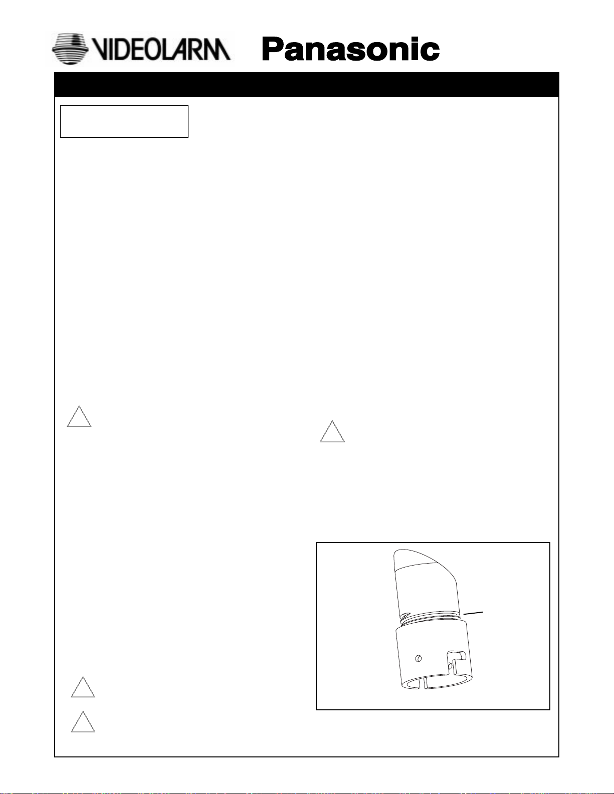
5. Open the housing by loosening the (9) captive screws located on
the housing ring next to the lower clear dome. Twist the dome
slightly in a counter clockwise motion to remove (Figure 2).
Loosen screws only,
do not remove
Remove dome by
twisting counterclockwise
Figure 2
8. Attach the unitized camera to the quick-release bracket. Secure
the safety screw (Figure 5). Connect the BNC and power cables.
Make sure all wiring is clear of the blowers and heater on the
housing bracket. Use the cable tie provided to secure the wires
and connectors.
Safety Screw
Figure 5
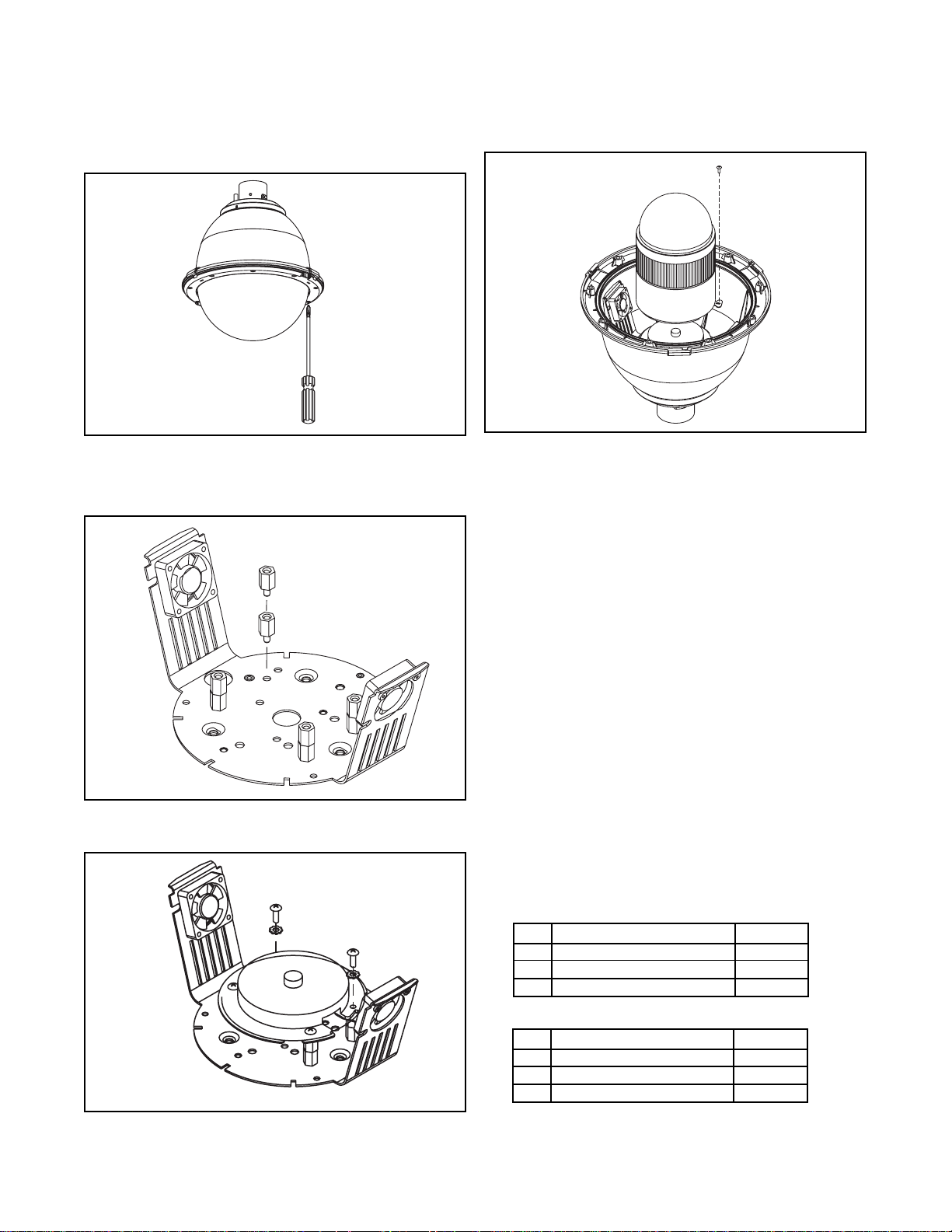
6. Spacers are provided to adjust the level of the WV-CS854
camera. Attach the spacers, two-high, to the quick-release
bracket (Figure 3).
Figure 3
7. Connect the quick-release bracket to the spacers using the (4) 8 x
32 x 1/2" bolts and #8 star washers (Figure 4).
9. A small 2” section of humidity sensitive paper is included in the
housing packet. Tape this to the side of the pan/tilt unit assembly
or inside the housing a visible location. The tape will appear blue
in tint when the humidity is low and turn pink under humid
conditions. This can provide a check to confirm that the housing
is sealed properly. The paper requires about 30 minutes to adjust
to the appropriate color.
10. Clean the inside of the dome, with the tex-wipe provide. Reattach
the housing dome and secure the (9) captive screws. Do not
overtighten the screws. Tighten only to the point at which the
gap between the ring and the housing top closes. Each screw
should then be turned 1/2 rotation beyond this point.
INSTALLING THE HOUSING ASSEMBLY
11. Mount the housing assembly to the mounting bracket and
housing coupling. A safety cable is included with the housing to
temporarily hold it while wiring connections. Loop the safety
cable over one of the set screws on the housing coupling and
make the appropriate connections using the (2) screw-down
connectors supplied.
Wiring Color Code
Power Inputs
(Outside housing)
CAMERA POWER
1 Camera Power (24 VAC) Red
2 Camera Power (24 VAC) Orange
3 Ground White
4 N/C
Figure 4
ACCESSORY POWER
1 Accessory Power (24 VAC) Yellow
2 Accessory Power (24 VAC) Green
3 N/C
4 N/C
- 2 -
Page 3

CAUTION: TO PREVENT FIRE OR SHOCK HAZARD, THE UL-
!
LISTED WIRE VW-1, STYLE 1007, SHOULD BE USED FOR THE
CABLE FOR 24 VAC INPUT TERMINALS.
OPERATING DISTANCES FOR POWER LINES
Awg Size Impedance Max Distance
Awg #12 1.71 ohm/1000 ft. 440 ft.
Awg #14 2.73 ohm/1000 ft. 270 ft.
Awg #16 4.35 ohm/1000 ft. 170 ft.
Awg #18 6.92 ohm/1000 ft. 100 ft.
PRESSURIZING THE ENCLOSURE
Air is inserted in the enclosure through the Schraeder valve located
on the top of the unit. A pressure release valve is located under the
housing cap located in this same location. Air vents from the
pressure release valve between the housing top and the cap.
Vent holes
Figure 4
Schraeder
valve
12. Undo the safety cable and twist the housing onto the
housing coupling. Secure all (3) set-screws provided on the
housing coupling (Figure 3).
Set screws
Figure 3
13. Clean the outside of the dome with the text wipe
Before inserting air into the housing be sure the (2) cap
vents are free of obstructions such as ice or debris. (Fig 4)
Pressurized housings provide maximum protection for CCTV
cameras and lenses. The charge of dry nitrogen inside the housing
eliminates the effects of moisture, dust, insects and corrosive
exhaust fumes, allowing a longer life for your surveillance equipment.
To pressurize the housing, you must have the following:
1. A tank of dry nitrogen
2. A regulator on the tank
3. A hose with air chuck to connect the regulator to the housing’s
intake valve
Dry Nitrogen
Nitrogen is a readily available; check your local yellow pages for a
medical or industrial gas provider. If the tank is to be carried from
location to location, a size of 40 cubic foot is recommended. This
should be enough to refill 30 individual housings. Handle the tanks
with care. Although nitrogen is an inert gas, the tank is highly
pressurized and if the valve or regulator is damaged the tank could
be dangerous. Tanks of dry nitrogen can be kept for several years.
The Regulator
The tank will have a standard 580 fitting, but a regulator will be
required. A recommended regulator for the tank would be a Harris
#9296-15-580 or #425-15-580. For local distribution you can contact
Harris at 800-241-0804.
The Hose
The purge valve, called a “Schraeder” or “dill” valve, is similar to the
air intake valve on car or bicycle tires. To connect the regulator to
the purge valve on the housing, you’ll need a hose with a 1/4” barb
on one end and an air chuck on the other. The barb connects to the
regulator, the air chuck to the Schraeder valve. These hoses can be
obtained at local auto parts stores.
Pressurizing the Housing
Set the gauge on the regulator to between 5 and 10 psi. Place the
air chuck on the Schraeder valve, just as you would on a tire, and
press down to begin filling. Air should start venting from the pressure
release valve after a few minutes. Once you’ve completed filling the
housing, check the pressure with a pressure gauge. It should be 3 5 psi. When you have verified the pressure, reconnect the air chuck
and purge the housing for an additional two minutes.
- 3 -
Page 4

EXPLODED VIEW OF HOUSING
Parts List
1. Pressured Sealed Housing
2. Housing Coupling
3. Housing Packet
a. (2) Screw down connectors
b. (4) Mounting 8 x 32 x 1/2" Mounting Screws
c. (4) #8 star washers
d. Humidity strip
e. Instruction Manual
f. Cable ties
g. (8) Metal spacers
Item No. Description Part No. Quantity
1 25W Heater w/ Leads 72-HT1752 2
2 PFD8 Housing Top 21-TOPFD8 1
3 Dome Support Ring 30-VL1695 1
4 Captive Screw 30-VL1749 9
n/s Captive Screw Spring 92-SPR01 9
n/s Captive Screw Retainer 94-FSRT04 9
5 PFD8 Clear Dome 20-DCPFD8 1
n/s PFD8 Tinted Dome 20-DTPFD8 1
6 9.25" O-ring 96-RSORG11 2
7 Main Housing Bracket 30-VL1742 1
n/s Main Housing 10 x 32 x 1/2” Bolts 3
8 Housing Fan 71-VLBL03 2
9 1/4 x 20 Set Bolts 3
10 Black Plastic Housing Cover 30-VL1802 1
11 4.50” O-ring 96-RSORG10 1
12 Inner Sealing Plate 30-VL1760 1
13 Housing Mounting Coupling 30-VL1759 1
14 Main Bracket Standoffs 30-VL1797 3
n/s 1/4 Lock Washers 92-WSSL01 3
17 PFD8 PCB 76-FPD8P2 1
18 3-5 lbs Pressure Relief Valve 95-VALV04 1
19 Shraeder Valve 95-VALV07 1
20 Housing Coupling 30-VL917 1
21 Shraeder Valve Grommet 30-VL1795 1
22 Housing Gasket 96-PSGK06 1
23 8 x 32 x 1/2” Flat Head 3
24 Hermetic Connector 70-PT08 1
n/s Eternal Leads to Hermetic Connect 40-CAPD801 1
n/s Hermetic to PCB Cable Assembly 40-CAPD802 1
n/s Housing Lanyard 30-VL1821 1
n/s Housing Packet 40-PKPFD8K 1
22
13
2
6
11
19
18
14
7
20
9
21
10
23
24
12
17
1
8
5
3
4
- 4 -
Page 5

1. Read Instructions - All the safety and operating instructions
!
should be read before the unit is operated.
2. Retain Instructions - The safety and operating instructions
should be retained for future reference.
3. Heed Warnings - All warnings on the unit and in the operating
instructions should be adhered to.
4. Follow Instructions - All operating and user instructions should
be followed.
5. Electrical Connections - Only a qualified electrician should
make electrical connections.
6. Attachments - Do not use attachments not recommended by the
product manufacturer as they may cause hazards.
7. Cable Runs - All cable runs must be within permissible distance.
8. Mounting - This unit must be properly and securely mounted to
a supporting structure capable of sustaining the weight of the
unit. Accordingly:
a. The installation should be made by a qualified service
person, and should conform to all local codes.
b. Care should be exercised to select suitable hardware to
install the unit, taking into account both the composition of the
mounting surface and the weight of the unit. Be sure to
periodically examine the unit and the supporting structure to
make sure that the integrity of the installation is intact. Failure
to comply with the foregoing could result in the unit separating
from the support structure and falling, with resultant damages
or injury to anyone or anything struck by the falling unit.
SAFETY PRECAUTIONSIMPORTANT SAFEGUARDS
CAUTION
RISK OF
ELECTRIC SHOCK!
CAUTION: TO REDUCE THE RISK OF
ELECTRICAL SHOCK, DO NOT EXPOSE
COMPONENTS TO WATER OR MOISTURE.
The lightning flash with an arrowhead symbol,
within an equilateral triangle, is intended to
alert the user to the presence of non-insulated
"dangerous voltage" within the product's
enclosure that may be of sufficient magnitude
to constitute a risk of electric shock to persons.
The exclamation point within an equilateral
triangle is intended to alert the user to
!
UNPACKING
Unpack carefully. Electronic components can be
damaged if improperly handled or dropped. If an item
appears to have been damaged in shipment, replace it
properly in its carton and notify the shipper.
presence of important operating and
maintenance (servicing) instructions in the
literature accompanying the appliance.
Be sure to save:
1. The shipping carton and packaging material. They are the
safest material in which to make future shipments of the
equipment.
2. These Installation and Operating Instructions.
SERVICE
For service on Panasonic/Videolarm equipment contact:
Panasonic Technical Center
54 West Gude Dr.
Rockville MD 20850-1150
Phone: 301-762-5125
Fax: 301-251-0347
PANASONIC TECHNICAL SUPPORT
1-800-528-6747
9:00 AM - 5:00 PM EASTERN TIME
- 5 -
 Loading...