

Panasonic Pod9cw, POD9CFW User Manual
Installation
Instructions
Outdoor Domed Housings
POD9C(W)/POD9CF(W)
Manufactured By:
Before attempting to connect or operate this product,
for
please read these instructions completely.
®
81-IN3079
6/8/05

!
!
1. Read Instructions - All the safety and operating instructions
should be read before the unit is operated.
2. Retain Instructions - The safety and operating instructions
should be retained for future reference.
3. Heed Warnings - All warnings on the unit and in the operating
instructions should be adhered to.
4. Follow Instructions - All operating and user instructions should
be followed.
5. Electrical Connections - Only a qualied electrician should make
electrical connections.
6. Attachments - Do not use attachments not recommended by the
product manufacturer as they may cause hazards.
7. Cable Runs - All cable runs must be within permissible
distance.
8. Mounting - This unit must be properly and securely mounted to
a supporting structure capable of sustaining the weight of the
unit. Accordingly:
a. The installation should be made by a qualied service person,
and should conform to all local codes.
b. Care should be exercised to select suitable hardware to
install the unit, taking into account both the composition of
the mounting surface and the weight of the unit. Be sure to
periodically examine the unit and the supporting structure to
make sure that the integrity of the installation is intact. Failure
to comply with the foregoing could result in the unit separating
from the support structure and falling, with resultant damages
or injury to anyone or anything struck by the falling unit.
SAFETY PRECAUTIONSIMPORTANT SAFEGUARDS
CAUTION
RISK OF
ELECTRIC SHOCK!
CAUTION: TO REDUCE THE RISK OF
ELECTRICAL SHOCK, DO NOT EXPOSE
COMPONENTS TO WATER OR MOISTURE.
The lightning ash with an arrowhead symbol,
within an equilateral triangle, is intended
to alert the user to the presence of noninsulated "dangerous voltage" within the
product's enclosure that may be of sufcient
magnitude to constitute a risk of electric shock
to persons.
The exclamation point within an equilateral
triangle is intended to alert the user to presence
of important operating and maintenance
(servicing) instructions in the literature
accompanying the appliance.
UNPACKING
Unpack carefully. Electronic components can be damaged
if improperly handled or dropped. If an item appears to have
been damaged in shipment, replace it properly in its carton
and notify the shipper.
Be sure to save:
1. The shipping carton and packaging material. They are the
safest material in which to make future shipments of the
equipment.
2. These Installation and Operating Instructions.
SERVICE
For service on Panasonic/Videolarm equipment contact:
Panasonic Technical Center
54 West Gude Dr.
Rockville MD 20850-1150
Phone: 301-762-5125
Fax: 301-251-0347
PANASONIC TECHNICAL SUPPORT
1-800-528-6747
9:00 AM - 5:00 PM EASTERN TIME
- 2 -

!
!
ELECTRICAL SPECIFICATIONS (OUTDOOR ONLY):
INSTALLING PENDANT MOUNT (POD9CW/POD9CFW)
Power 24VAC, Class 2 Only
52 watts at 24 VAC (Heater & Blower) Accessory Power
Heater: 50 watts
Blower: 1.7 watts
13 watts Camera Power (models WV-CS954 & WV-CS574)
Input Connectors (outdoor units):
BNC
(2) 4 position Molex connectors (power)
(1) Phone style plug (control)
NOTE: This unit is designed for operation in an
upright position. Installing the unit
upside down may cause damage to the
internal equipment, and will void the
warranty.
GENERAL INSTRUCTIONS FOR MOUNTING HOUSING
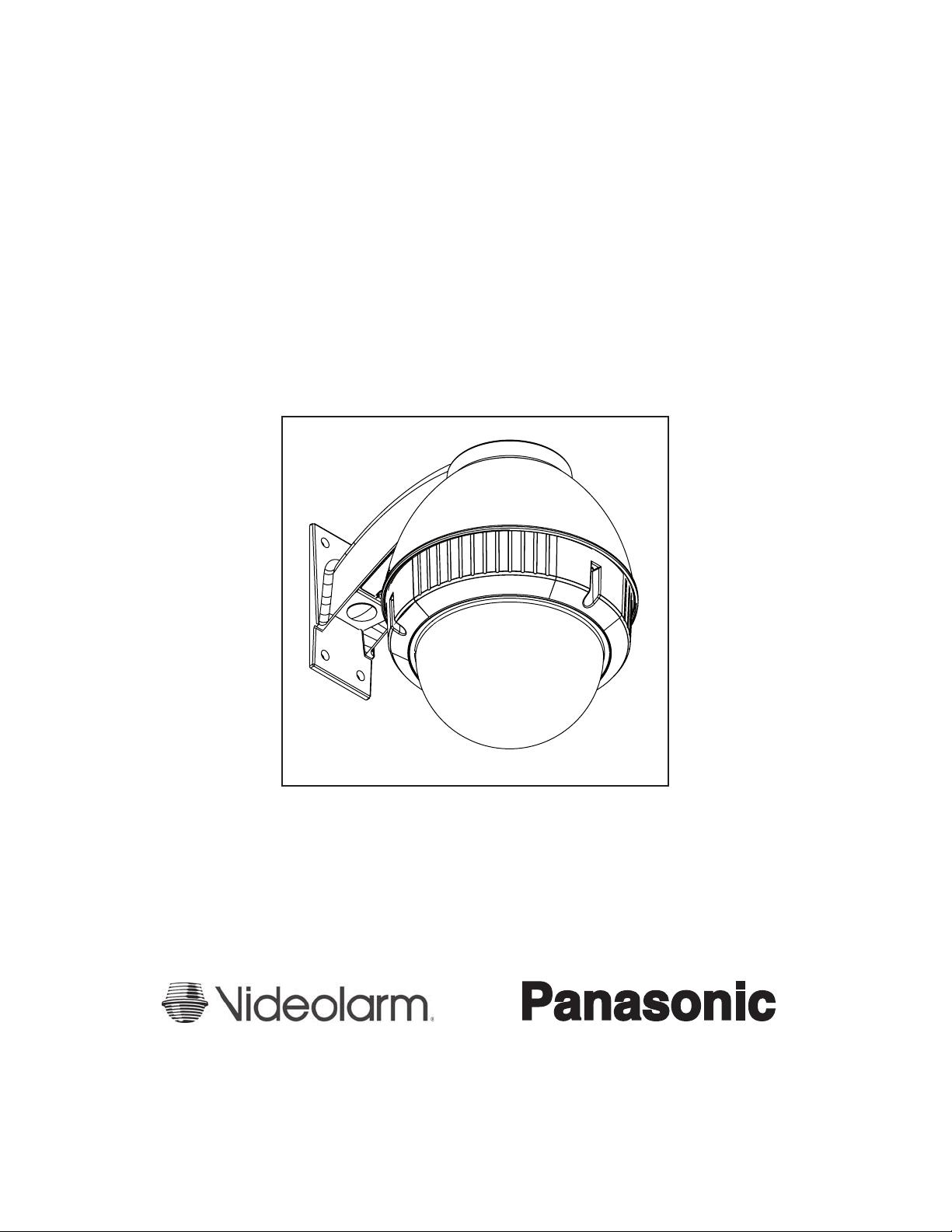
INSTALLING THE HOUSING ASSEMBLY FOR WALL MOUNT
POD9CW/POD9CFW
1. A wall mount bracket comes standard with this unit, and a
template is included to use as a guide for mounting the bracket
to a wall. Choose the desired location for installation and mark
the drill holes using the template.
NOTE: Be sure the hardware and the mounting surface can sup-
port the weight of the wall mount bracket plus the weight
of the housing and drive unit. The load will be subjected
to vibration from the camera motor and wind.
2. The wall mount bracket provided with the POD9CW includes
a location for conduit entry. If you wish to install conduit to the
bracket remove the conduit hole plug. Install tting from below the
wall mount and secure with conduit nut from inside the bracket.
1. This unit includes a 1 1/2" NPT coupling for a standard 1 1/2"
NPT pipe. The POD9 can be used with other brackets
designed with 1 1/2" male pipe threads, such as the Panasonic
PWM20G and PWM30G wall mount brackets.
2. Attach the housing coupling (Figure 2).
NOTE: Pipe threads should be clean and rust free. Use a
sealer (such as Teon™ tape or silicone sealer) on the
threads.
Add thread sealing tape
Figure 2
1. Mount the housing assembly to the mounting bracket and
housing coupling. A safety cable is included with the housing to
temporarily hold it while making wiring connections. Loop the
safety cable over one of the set screws on the housing coupling
and make the appropriate connections using the wiring chart
supplied on Page 4.
Make sure set screw is
secure before hanging
housing from screw
Figure 3
3. Open the access door on the bottom of the wall mount by
loosening the screw nearest the mounting plate (Figure 1).
Access panel
Figure 1
4. Attach the wires from the wall to the connector provided, using the
wiring color code chart as a guide.
5. Once all wiring connections are made, place the wires inside the
wall mount bracket and close the access door. Secure with the
screw removed earlier.
6. Clean the outside of the dome.
2. Upon completing wiring, undo the safety cable and twist the
housing onto the housing coupling. Secure all (3) setscrews
provided on the housing coupling (Figure 4).
- 3 -
3. Clean the outside of the dome.
Set screws
Figure 4
 Loading...