

Page 1
Installation
Instructions
Outdoor Domed Housings
POD9C(W)/POD9CF(W)
Manufactured By:
Before attempting to connect or operate this product,
for
please read these instructions completely.
®
81-IN3079
6/8/05
Page 2
!
!
1. Read Instructions - All the safety and operating instructions
should be read before the unit is operated.
2. Retain Instructions - The safety and operating instructions
should be retained for future reference.
3. Heed Warnings - All warnings on the unit and in the operating
instructions should be adhered to.
4. Follow Instructions - All operating and user instructions should
be followed.
5. Electrical Connections - Only a qualied electrician should make
electrical connections.
6. Attachments - Do not use attachments not recommended by the
product manufacturer as they may cause hazards.
7. Cable Runs - All cable runs must be within permissible
distance.
8. Mounting - This unit must be properly and securely mounted to
a supporting structure capable of sustaining the weight of the
unit. Accordingly:
a. The installation should be made by a qualied service person,
and should conform to all local codes.
b. Care should be exercised to select suitable hardware to
install the unit, taking into account both the composition of
the mounting surface and the weight of the unit. Be sure to
periodically examine the unit and the supporting structure to
make sure that the integrity of the installation is intact. Failure
to comply with the foregoing could result in the unit separating
from the support structure and falling, with resultant damages
or injury to anyone or anything struck by the falling unit.
SAFETY PRECAUTIONSIMPORTANT SAFEGUARDS
CAUTION
RISK OF
ELECTRIC SHOCK!
CAUTION: TO REDUCE THE RISK OF
ELECTRICAL SHOCK, DO NOT EXPOSE
COMPONENTS TO WATER OR MOISTURE.
The lightning ash with an arrowhead symbol,
within an equilateral triangle, is intended
to alert the user to the presence of noninsulated "dangerous voltage" within the
product's enclosure that may be of sufcient
magnitude to constitute a risk of electric shock
to persons.
The exclamation point within an equilateral
triangle is intended to alert the user to presence
of important operating and maintenance
(servicing) instructions in the literature
accompanying the appliance.
UNPACKING
Unpack carefully. Electronic components can be damaged
if improperly handled or dropped. If an item appears to have
been damaged in shipment, replace it properly in its carton
and notify the shipper.
Be sure to save:
1. The shipping carton and packaging material. They are the
safest material in which to make future shipments of the
equipment.
2. These Installation and Operating Instructions.
SERVICE
For service on Panasonic/Videolarm equipment contact:
Panasonic Technical Center
54 West Gude Dr.
Rockville MD 20850-1150
Phone: 301-762-5125
Fax: 301-251-0347
PANASONIC TECHNICAL SUPPORT
1-800-528-6747
9:00 AM - 5:00 PM EASTERN TIME
- 2 -
Page 3

!
!
ELECTRICAL SPECIFICATIONS (OUTDOOR ONLY):
INSTALLING PENDANT MOUNT (POD9CW/POD9CFW)
Power 24VAC, Class 2 Only
52 watts at 24 VAC (Heater & Blower) Accessory Power
Heater: 50 watts
Blower: 1.7 watts
13 watts Camera Power (models WV-CS954 & WV-CS574)
Input Connectors (outdoor units):
BNC
(2) 4 position Molex connectors (power)
(1) Phone style plug (control)
NOTE: This unit is designed for operation in an
upright position. Installing the unit
upside down may cause damage to the
internal equipment, and will void the
warranty.
GENERAL INSTRUCTIONS FOR MOUNTING HOUSING
INSTALLING THE HOUSING ASSEMBLY FOR WALL MOUNT
POD9CW/POD9CFW
1. A wall mount bracket comes standard with this unit, and a
template is included to use as a guide for mounting the bracket
to a wall. Choose the desired location for installation and mark
the drill holes using the template.
NOTE: Be sure the hardware and the mounting surface can sup-
port the weight of the wall mount bracket plus the weight
of the housing and drive unit. The load will be subjected
to vibration from the camera motor and wind.
2. The wall mount bracket provided with the POD9CW includes
a location for conduit entry. If you wish to install conduit to the
bracket remove the conduit hole plug. Install tting from below the
wall mount and secure with conduit nut from inside the bracket.
1. This unit includes a 1 1/2" NPT coupling for a standard 1 1/2"
NPT pipe. The POD9 can be used with other brackets
designed with 1 1/2" male pipe threads, such as the Panasonic
PWM20G and PWM30G wall mount brackets.
2. Attach the housing coupling (Figure 2).
NOTE: Pipe threads should be clean and rust free. Use a
sealer (such as Teon™ tape or silicone sealer) on the
threads.
Add thread sealing tape
Figure 2
1. Mount the housing assembly to the mounting bracket and
housing coupling. A safety cable is included with the housing to
temporarily hold it while making wiring connections. Loop the
safety cable over one of the set screws on the housing coupling
and make the appropriate connections using the wiring chart
supplied on Page 4.
Make sure set screw is
secure before hanging
housing from screw
Figure 3
3. Open the access door on the bottom of the wall mount by
loosening the screw nearest the mounting plate (Figure 1).
Access panel
Figure 1
4. Attach the wires from the wall to the connector provided, using the
wiring color code chart as a guide.
5. Once all wiring connections are made, place the wires inside the
wall mount bracket and close the access door. Secure with the
screw removed earlier.
6. Clean the outside of the dome.
2. Upon completing wiring, undo the safety cable and twist the
housing onto the housing coupling. Secure all (3) setscrews
provided on the housing coupling (Figure 4).
- 3 -
3. Clean the outside of the dome.
Set screws
Figure 4
Page 4

WJ-HD316A
Approx. 0.1"
Wire
Insert
Up
Contact
Wire
Up
Contact
1
2
4
3
1
2
4
3
WU-CU650
Wiring Color Code
Power and Control Inputs
POD9C
CONNECTOR A
CAMERA POWER [13 watts WV-CS954 / WV-CS574]
1 24 VAC Live Black
2 24 VAC Live White
3 Green Green
4 Not Used
CONNECTOR B
ACCESSORY POWER [52 watts Heater/Blower]
1 24 VAC Live Red
2 24 VAC Live White
3 Green Green
4 Not Used
Pan/Tilt Unit Only
CONTROL
HOW TO ASSEMbLE THE CONNECTOR
• Strip back the cable jacket approximately 0.1 inch
(3 mm) and separate the individual conductors.
Prepare the individual conductors for clamping. If
clamping, use Molex brand tool part number 570275000 (for UL-listed-style cable UL1015) or 57026-5000
(for UL-listed-style cable UL1007).
After clamping the contacts, push them into the
proper holes in the connector housing until they
snap in place.
1 Ground Brown
2 TXB (RS485) Red
3 TXA (RS485) Orange
4 RXB (RS485) Yellow
5 RXB (RS485) Green
ALARM IN (8-pin)
1 Alarm In 1 Black
2 Ground Brown
3 Alarm In 2 Red
4 Ground Orange
5 Alarm In 3 Yellow
6 Ground Light blue or green
7 Alarm In 4 Blue
8 Ground Purple
ALARM OUT (4-pin)
1 Alarm Out 1 Gray
2 Ground White
3 Alarm Out 2 Pink
4 Ground Yellow, Green, or Light blue
CAUTIONS
• Shrinking the cable-entry seal is a onetime
procedure. Do not shrink the cable-entry seal
until it has been determined that the unit is
functioning.
• CONNECT THIS TO A 24 VAC CLASS 2 POWER
SUPPLY ONLY.
CAUTION: TO PREVENT FIRE OR SHOCK HAZARD, THE
UL-LISTED WIRE VW-1, STYLE 1007, SHOULD BE USED
FOR THE CABLE FOR 24 VAC INPUT TERMINALS.
CAUTION: For lightning protection of the camera
and heater/blower, the pin 3 of the connector
must be connected to real electrical ground.
OPERATING DISTANCES
Awg Size Impedance Max Distance
Awg #12 1.71 ohm/1000 ft. 440 ft.
Awg #14 2.73 ohm/1000 ft. 270 ft.
Awg #16 4.35 ohm/1000 ft. 170 ft.
Awg #18 6.92 ohm/1000 ft. 100 ft.
- 4 -
Page 5

INSTALLING QUICK RELEASE BRACKET AND PAN/TILT
!
CAMERA ASSEMBLY (ALL MODELS)
1. Open the housing by loosening the (3) screws on the dome
trim ring (Figure 1). Note the arrows and the word "Locked" on
the side of the housing and trim ring. Rotate the trim ring until
the bottom arrow aligns with the second top arrow, then pull
the dome and trim ring off.
Make sure all (3)
captive bolts drop
away from trim ring
before turrning!
Figure 1
2. Install the pan/tilt unit quick- release bracket. It is recom-
mended that this be done before installing the housing.
INSTALLATION FOR WV-CS574 UNITIZED CAMERA
1. Installation for WV-CS574 Unitized Camera. Add additional 1"
spacers (from packet assembly) to the existing spacer already
installed in housing. Connect he quick release bracket using
the (4) 8x32x1/2 bolts and #8 star washers (Figure 1b).
Add 1" Spacers
Figure 1b
INSTALLATION FOR WV-CS954 UNITIZED CAMERA
1. Connect the quick-release bracket to the spacers using the (4)
8 x 32 x 1/2" bolts and #8 star washers to the top of the spacers
as shown (Figure 1a).
Figure 1a
2. Attach the unitized camera to the quick-release bracket.
Secure the safety screw (Figure 2). Connect the BNC, power,
control, and alarm cables. Make sure all wiring is clear of the
blowers and heater on the housing bracket. Use the cable tie
provided to secure the wires and connectors.
2. Attach the unitized camera to the quick-release bracket.
Secure the safety screw (Figure 2). Connect the BNC, power,
control, and alarm cables. Make sure all wiring is clear of the
blowers and heater on the housing bracket. Use the cable tie
provided to secure the wires and connectors.
Figure 2
- 5 -
Page 6

INSTALLING FIXED CAMERA BRACKET (ALL MODELS)
1. Loosen the two pan adjustment screws and rotate the bracket to
the desired viewing location.
Pan
adjustment
screw
Pan
adjustment
screw
Figure 3
2. Tilt and height adjustments can be made using the two screws
located on the upper portion of the xed camera bracket. Loosen-
ing the screws allows the bracket itself to slide up and down the
bracket arms (height adjustment) and back and forth on the cam-
era bracket (tilt). Adjust to the desired location (Figure 4).
NOTE: A 90˚ BNC connector is included in the
packet to assist in tting the camera (Figure 6).
Figure 6
4. Attach the camera to the bracket using the 1/4-20 hex bolt
provided. Make nal adjustments and lock down the pan, tilt, and
height adjustment screws (Figure 7).
IMPORTANT NOTE: Put the dome in place to assure the camera
does not touch it. To reattach the dome you must twist it, if the
dome comes in contact with the camera its position could change.
1/4-20 hex bolt
Figure 4
3. The camera can also be adjusted back and forth via the slot
located on the bottom of the bracket (Figure 5).
Tilt
adjustment
screw
Figure 7
Figure 5
- 6 -
Page 7

12
13
14
15
2
11
5
8
3
4
7
10
6
9
1
EXPLODED VIEWS OF HOUSING
Wall Mount Assembly
Item No. Description Part No.
1 Lower Trim Ring RPPOD01
2
3
4
5
6
7
8
9
10 Panasonic Wall Mount PWM10
11
Tinted Replacement Capsule
Clear Replacement Capsule
Dome Clamping Bracket RPFD703
24vac Heater RPFD072
(12vdc) Blower (Used In 24v Hgs) RPFD080
Camera Bracket
Camera Bracket (Fixed Models Only)
Connection PCB
Connection PCB (Fixed Models)
Housing Hardware RPFD040
Housing Top RPPOD08
Captive Hardware (3 Pcs) RPPOD09
RCPOD9T
RCPOD9C
RPFD060
RPRH708
RPFD050
(Model POD9CW)
RPRH706
(Model POD9CFW)
Fixed Bracket Assembly
15 POD9CF Fixed Bracket RPRH713
N/S Packet Assembly POD9CF(W) RPPKPOD9F
Packet Assembly POD9C(W) RPPKPOD9
Pendant Coupling Assembly
12 Quick Release Pipe Coupling SD0170
13 Pendent Housing Coupling RPPOD10
14 Pendent Mount Bracket RPPOD11
- 7 -
Page 8
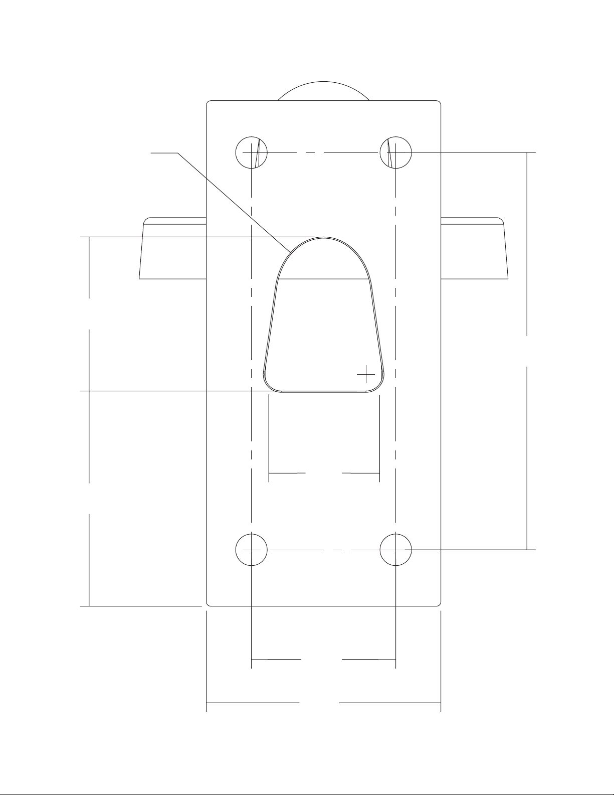
2.000
3.250
R .733
2.132
2.981
1.537
5.500
Mounting Template
- 8 -
 Loading...