

Page 1
C
D
B
A
F
E
INSTRUCTIONS TO MOUNT, ASSEMBLE, WIRE & INSTALL
THE 8” ENVIRONMENTAL GLOBE FOR PTZ CAMERAS
O U T D O O R S O L U T I O N S :
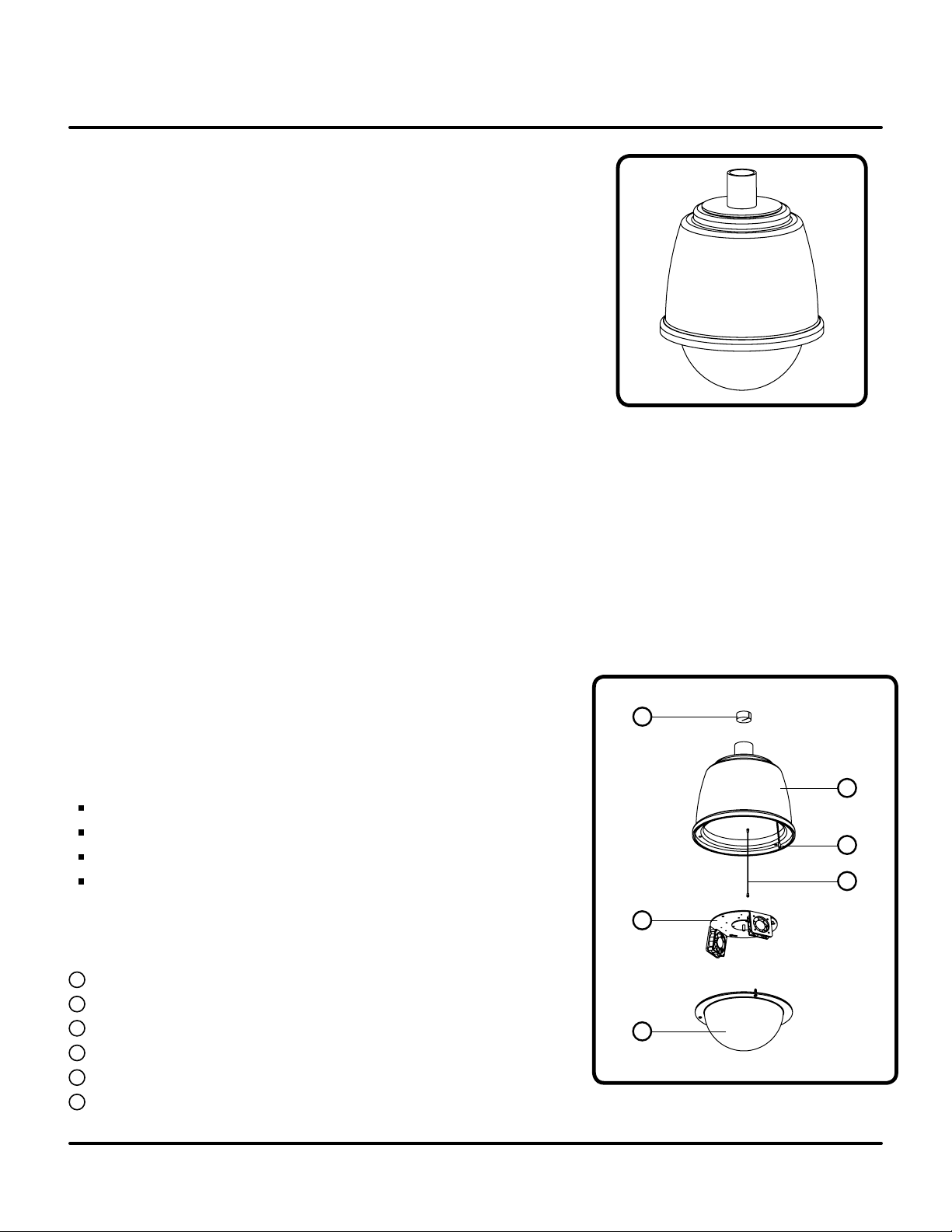
POD8CB
8” EN VIRONME NTAL GLOBE
FO R PTZ CAME RAS
MO UNTS
Curved Wall Mount P
Pole Adapter PAPM3
Corner Adapter PACA2
WM20G
CO MPATI BLE PTZ
s
WV-CS574
WV-CS954
WV-NS324
SU GGESTED INSTALLATION EQUIPMENT
#2 Phillips-head screwdriver
” Wrench or socket
7/16
Outdoor-approved pipe thread sealant (included)
Tamper-proof hex key wrench
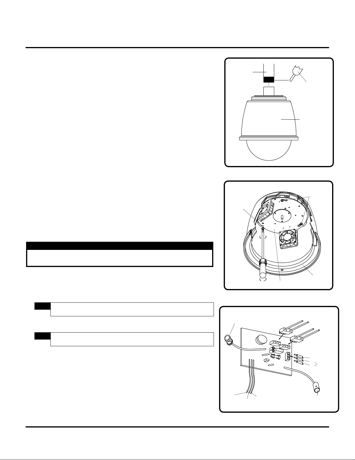
C O M P O N E N T L I S T
A
Foam Dust Plug
B
Housing (outer shell and inner lining)
C
Dome Safety Tether
D
Mounting Plate Safety Tether
E
Camera Mounting Plate (with circuit board and optional heater/blower)
F
8” Dome
(included)
[ F I G U RE 1 ]
FI G U RE 1
F O R T E C H N I C A L S U P P O R T - C A L L 1 - 8 0 0 - 5 2 8 - 6 7 4 7 O R FAX 1 - 8 8 8 - 8 0 9 - 6 1 9 8
Specifi cations are subje ct to change wi thout no tice. ©2 005. All rights reserve d.
7L198 rev-d PAGE 1 of 4
Page 2
VI DE O IN
FR OM C AM ERA
L2
(B LA CK )
L1
(W HI TE )
GR OU ND ( GRE EN )
24 VAC TO
CA ME RA
VI DE O OU T
TO M ON IT OR
GR OU ND
L2
L1
24 VA C I N
TO
HE AT ER
TO
BL OW ER
AP PLY PI PE T HR EA D
SE AL ER T O T HR EA DS
BE FO RE I NSTA LLI NG
HO US IN G
1. 5” N PT
MO UN T
HO US IN G
LO OS EN T HES E
TW O SC RE WS
FI RS T.. .
.. .T HE N REM OV E
TH IS S CR EW
HO US IN G
MO UN TI NG PL ATE
INSTRUCTIONS TO MOUNT, ASSEMBLE, WIRE & INSTALL
THE 8” ENVIRONMENTAL GLOBE FOR PTZ CAMERAS
WA R N I N G S A N D S A F E G U A R D S
Prior to installation and use of this product, please observe the following warnings
1. Installation and servicing should be performed by qualified personnel only.
2. All work should conform to local building codes.
3. Use only approved replacement parts or supplied accessories. Failure to comply
may invalidate remaining warranty period.
4. Verify proper location and installation of the housing mount (1½
” NPT pipe or approved
mount). The pipe or mount shall be capable of supporting three (3) times the weight
of the housing and its contents.
5. Verify proper installation of cabling to support camera power, video and data
requirements for PTZ camera applications.
6. The Environmental Globe is designed to be operated by a 24VAC regulated power
source capable of supporting 2.0 amps plus required amperage for the selected camera(s).
FI G U RE 2
INSTA LLAT I O N
1. Carefully unpack box and verify that all components listed are included.
2. Apply thread sealant (included) to the 1½” NPT pipe threads or approved mount. This
procedure will prevent moisture ingress through the threads.
3. Install Environmental Globe assembly on 1½
clockwise until threads are fully engaged.
4. Remove the dome assembly by loosening the three (3) tamper-proof screws (wrench supplied)
and suspend from supplied tether strap.
protective film in place until installation is complete.
5. Remove mounting plate by loosening screws and removing screw, as shown.
stand-offs before installing the PTZ.
6. Allow mounting plate to be suspended by tether strap.
7. Remove foam dust cap and route power, video and data cables into the assembly.
Route leads of mounting base through the mounting plate and secure base
to mounting plate with included screws.
8. Connect 24VAC to AC terminals on circuit board.
9. Connect the BNC terminal of the outgoing video cable to the “video out to monitor”
connection on circuit board and wrap connection with electrical tape.
Specifi cations are subje ct to change wi thout no tice. ©2 005. All rights reserve d.
[ FI GU R E 2 ]
! ! WA R N I N G ! !
Failure to properly seal the 1½” NPT pipe threads will permit water
to enter the housing and may damage the equipment.
” NPT pipe or mount by rotating counter-
NOTE:
Use caution when handling the dome as not to damage the surface and leave
NOTE:
If installing WV-NS324, remove the spacers underneath the three (3)
[ FI GU R E 4 ]
F O R T E C H N I C A L S U P P O R T - C A L L 1 - 8 0 0 - 5 2 8 - 6 7 4 7 O R FAX 1 - 8 8 8 - 8 0 9 - 6 1 9 8
[ FI GU R E 1 ]
[ F IG URE 3 ]
[ FI GU R E 4 ]
FI G U RE 3
FI G U RE 4
7L198 rev-d PAGE 2 of 4
Page 3

5- PO SI TI ON BA RR IE R ST RI P
12
-P OS IT IO N B AR RI ER S TR IP
INSTRUCTIONS TO MOUNT, ASSEMBLE, WIRE & INSTALL
THE 8” ENVIRONMENTAL GLOBE FOR PTZ CAMERAS
INSTA LLAT I O N
10. Connect the alarm-in and alarm-out wiring to the 12-position barrier strip and the
data line to the 5-position barrier strip by matching the colored wires to the color coded connections.
NOTE:
Wires are color-coded and labeled on the unit.
[ FI GU R E 5 ]
11. Connect power to the camera to the power-out from PCB. Re-install the foam dust
cap in the cable entrance of the housing.
12. Re-install mounting plate in unit and install PTZ per camera installation
instructions.
13. Re-install dome assembly and securely tighten screws and remove protective film from
the dome.
FI G U RE 5
T R O U B L E S H O O T I N G
P R O B L E M
No video.
P O S S I B L E C A U S E S
No power to camera.
Broken power lead from PC board
to camera.
Defective camera.
Broken video cable from camera to
PC board.
Broken video cable from PC board
to output video lead.
Faulty connection at BNC
connectors.
Fan will not run.
No power to PC board.
Loose connection at connector.
Broken fan wire.
Obstruction in fan wire blades.
P O S S I B L E S O L U T I O N S
Verify that there is 24VAC (+/– 10%) to the voltage input terminals
of PC Board and to camera voltage input terminals.
Check for power lead.
Verify proper performance of camera without interfacing with PC board,
by making direct connection of camera to monitor
Verify that the video cable is intact and not damaged or broken.
Verify that the video cable is intact and not damaged or broken.
Check for proper connection at the BNC connector and that the co-axial
.
shield is not contacting the center conductor.
Check to make sure 24VAC (+/– 10%) is applied to input terminals of
PC board.
Check to make sure proper fan connection is made to PC board.
[ FI GU R E 4 ]
Check for broken fan wire.
Check fan blades for obstruction or interference.
Heater will not heat.
No power to PC board.
Loose connection at PC board
connector.
Broken heater wire.
F O R T E C H N I C A L S U P P O R T - C A L L 1 - 8 0 0 - 5 2 8 - 6 7 4 7 O R FAX 1 - 8 8 8 - 8 0 9 - 6 1 9 8
Specifi cations are subje ct to change wi thout no tice. ©2 005. All rights reserve d.
Check to make sure 24VAC (+/– 10%) is applied to input terminals of
PC board.
Check to make sure proper heater connection is made to PC board.
[ FI GU R E 4 ]
Check for broken heater wire.
7L198 rev-d PAGE 3 of 4
Page 4

10.7
8.0
8.2
3.83
2.3
INSTRUCTIONS TO MOUNT, ASSEMBLE, WIRE & INSTALL
THE 8” ENVIRONMENTAL GLOBE FOR PTZ CAMERAS
M E C H A N I C A L P R O P E R T I E S
Upper unit (outer shell) .125 weatherable cap ABS (UV resistant)
Upper unit (inner shell) .187
” HIPS (94HB)
Lower unit .118” cell-cast acrylic (94HB)
Hardware 12 gauge steel construction with black powder-coat finish
Weight (without PTZ) Basic unit: 5.06 lbs
(shipping weight: 7.58 lbs)
Unit with heater/blower kit: 5.26 lbs
(shipping weight: 7.78 lbs)
E L E C T R I C A L P R O P E R T I E S
Input Voltage 24VAC +/- 10%
Power Requirements 1 heater, 2 blowers = 1.8 amps (PTZ not included)
Blowers (2) = 24.8 CFM @ .006 watts (.16 amps)
(continuous operation)
Heater (1) 40 watt heater
D I M E N S I O N S
( All Dimensions Are in Inches )
C E R T I F I C ATI O N S
Designed to meet NEMA-4 guidelines and independently certified to IP66
requirements with proper installation
E N V I R O N M E N T
Outdoor with Heater/Blower -20°F to 120°F
Specifi cations are subje ct to change wi thout no tice. ©2 005. All rights reserve d.
F O R T E C H N I C A L S U P P O R T - C A L L 1 - 8 0 0 - 5 2 8 - 6 7 4 7 O R FAX 1 - 8 8 8 - 8 0 9 - 6 1 9 8
7L198 rev-d (05/11/05) PAGE 4 of 4
 Loading...