

Page 1
Manufactured by:
81-IN3062-9922
Before attempting to connect or operate this product, please read these instructions completely.
for
MODEL: POD7U
Contents:
Qty. Description
(1) POD7U housing (21-TOPOD7U)
(1) 1" pipe flange (30-VL982)
(4) WM2500 Male pins (70-WPMX05)
(1) Molex connectors (70-WPMX11)
(4) 8-32 x 1/2" Phillips head screws (90-BTRP19)
(2) Nylon cable ties (94-FSCT01)
Use only Class 2 power suppliies
!
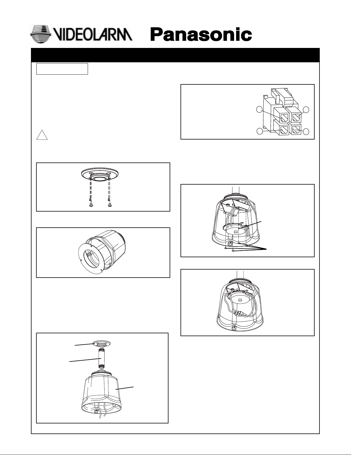
1. Mount the pipe flange in the selected location (Figure 1,
hardware not suppllied). Run all wiring through the pipe
flange hole.
Figure 1
PRODUCT INSTRUCTIONS
5. Apply connectors to the incoming wiring using the
following chart as a guide.
Connector - Camera Power
Connector Information Pin
1. AC 24 VAC Live
2. AC 24 VAC Neutral
3. Ground
4. Not Used
CAUTION: For lightning protection of the camera, pin 3 of
the connector must be connected to real
electrical ground.
6. Detach the Camera Mounting Base and mount it
to the camera bracket using the (4) 8-32 x 1/2" Phillips
head screws provided (Figure 4).
3
1
4
2
2. Loosen the three 8-32 x 3/8" Phillips head screws and
remove the trim ring (Figure 2).
Figure 2
3. Attach a 1" diameter pipe (not supplied) to the pipe
flange, passing all wiring through the pipe first (Figure 3).
4. Attach the housing to the pipe (Figure 3)
NOTE: To assure a water-tight fit, use a silicone sealer or
Teflon™ tape on the pipe threads. If the cabling
is exposed to the elements, be sure to make a
drip loop before entering the pipe flange.
Pipe Flange
1" pipe
(not supplied)
Camera Mounting
Base
for WV-CS854
Figure 4
7. Make all electrical and video connections (Figure 5).
Figure 5
8-32 x 3/8" Phillips
head screws
Figure 3
Housing
Page 2
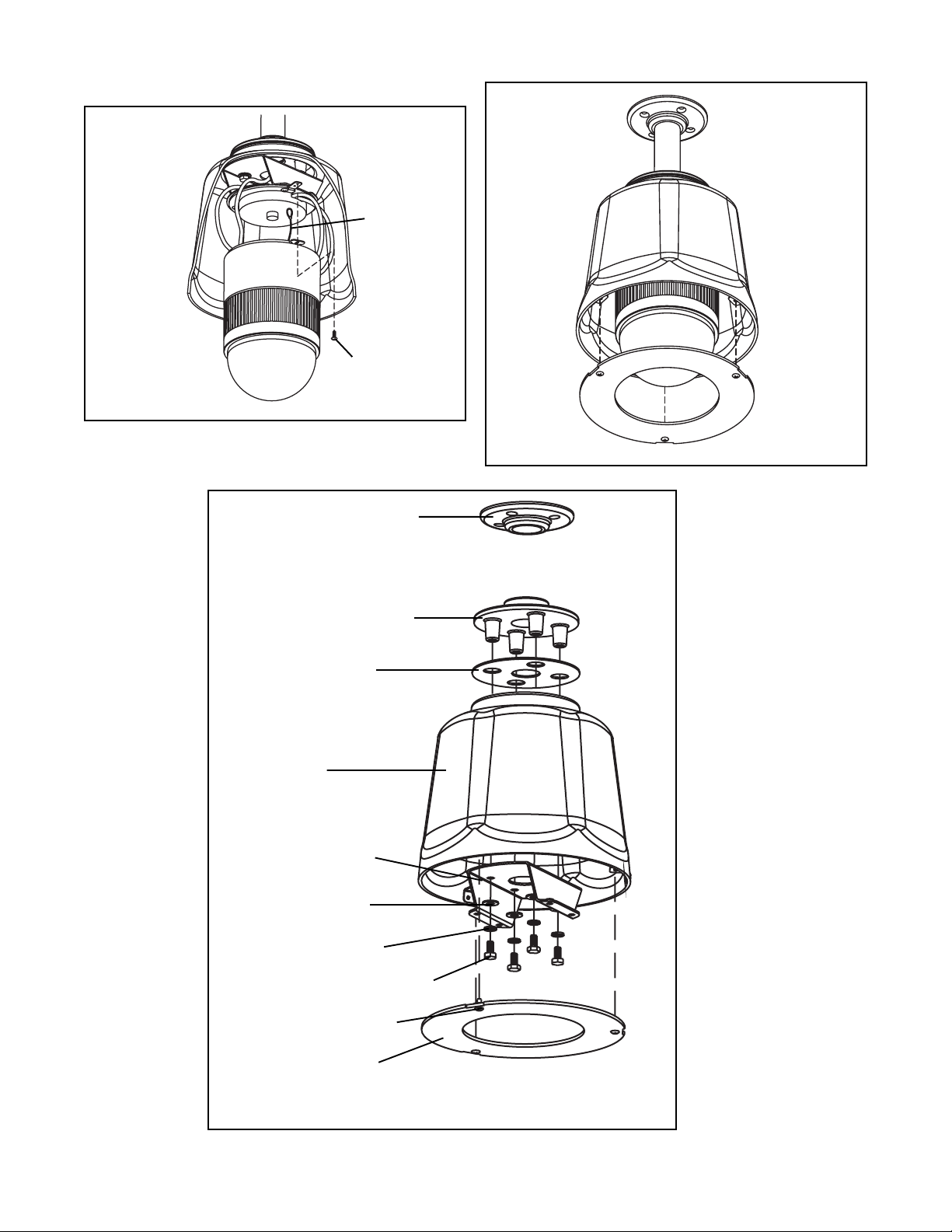
8. Attach the camera to the Quick Release Plate. Be sure
to connect the retractable lanyard to the plate first.
Finish with the locking screw (Figure 6).
Lanyard
Locking Screw
(included with
Figure 6
camera)
9. Replace the trim ring (Figure 7).
Figure 7
Pipe Flange
30-VL982
Mounting Bracket
30-VL1013
Top Gasket
96-PSGK05
Housing
21TOPOD7U
Upper Housing Bracket
30-VL1699
1/4 SAE Flat Washer
92WSFL01
1/4 Split Lockwasher
92-WSSL01
1/4-20 x 1/2 Hex Head Screw
90-BTHH32
8-32 x 3/8 Phillips Head Screw
90-BTRP19
Trim Ring
21-TRPOD7U
Not Shown: White Nylon 8-32 retainers
94-FSRT04
- 2 -
Page 3

1. Read Instructions - All the safety and operating instructions
!
should be read before the unit is operated.
2. Retain Instructions - The safety and operating instructions
should be retained for future reference.
3. Heed Warnings - All warnings on the unit and in the operating
instructions should be adhered to.
4. Follow Instructions - All operating and user instructions should
be followed.
5. Electrical Connections - Only a qualified electrician should
make electrical connections.
6. Attachments - Do not use attachments not recommended by the
product manufacturer as they may cause hazards.
7. Cable Runs - All cable runs must be within permissible distance.
8. Mounting - This unit must be properly and securely mounted to
a supporting structure capable of sustaining the weight of the
unit. Accordingly:
a. The installation should be made by a qualified service
person, and should conform to all local codes.
b. Care should be exercised to select suitable hardware to
install the unit, taking into account both the composition of the
mounting surface and the weight of the unit. Be sure to
periodically examine the unit and the supporting structure to
make sure that the integrity of the installation is intact. Failure
to comply with the foregoing could result in the unit separating
from the support structure and falling, with resultant damages
or injury to anyone or anything struck by the falling unit.
SAFETY PRECAUTIONSIMPORTANT SAFEGUARDS
CAUTION
RISK OF
ELECTRIC SHOCK!
CAUTION: TO REDUCE THE RISK OF
ELECTRICAL SHOCK, DO NOT EXPOSE
COMPONENTS TO WATER OR MOISTURE.
The lightning flash with an arrowhead symbol,
within an equilateral triangle, is intended to
alert the user to the presence of non-insulated
"dangerous voltage" within the product's
enclosure that may be of sufficient magnitude
to constitute a risk of electric shock to persons.
The exclamation point within an equilateral
triangle is intended to alert the user to
!
UNPACKING
Unpack carefully. Electronic components can be
damaged if improperly handled or dropped. If an item
appears to have been damaged in shipment, replace it
properly in its carton and notify the shipper.
presence of important operating and
maintenance (servicing) instructions in the
literature accompanying the appliance.
Be sure to save:
1. The shipping carton and packaging material. They are the
safest material in which to make future shipments of the
equipment.
2. These Installation and Operating Instructions.
SERVICE
For service on Panasonic/Videolarm equipment contact:
Panasonic Technical Center
54 West Gude Dr.
Rockville MD 20850-1150
Phone: 301-762-5125
Fax: 301-251-0347
PANASONIC TECHNICAL SUPPORT
1-800-528-6747
9:00 AM - 5:00 PM EASTERN TIME
- 3 -
 Loading...