

Page 1
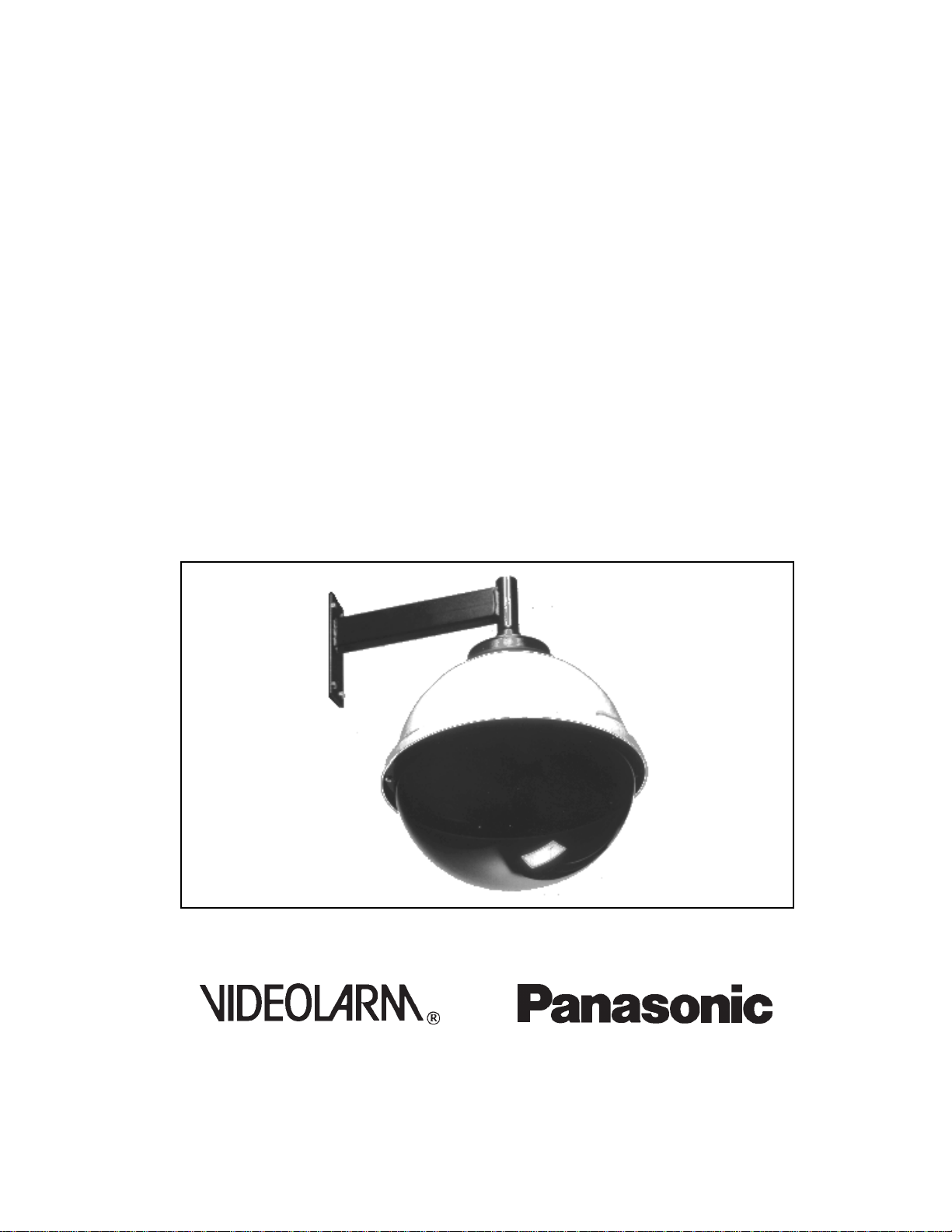
Installation
Instructions
Outdoor Domed Housings
POD-16C
Manufactured By:
Before attempting to connect or operate this product,
please read these instructions completely.
for
1
®
Page 2

• CAUTION
1. PRECAUTIONS ON INSTALLATION
2. DESCRIPTION
3. INSTALLATION
TABLE OF CONTENTS
3-1 Installation Steps
3-2 Pendent/Wall Mount Installation
3-3 Housing Assembly
3-4 Bracket Assembly
3-5 Camera Connections
3-6 Liner and Dome Installation
3-7 Care and Maintenance
4. SYSTEM CONNECTION
5. SPECIFICATIONS
2
Page 3

CAUTION
This unit must be properly and securely mounted to a supporting structure capable of sustaining the weight of the bracket
and camera assembly. Accordingly,
1. This installation should be made by a qualified
service person and should conform to all local
codes.
2. Care should be exercised to select suitable hardware to install the unit, taking into account both
the composition of the mounting surface and the
weight the hardware will be required to sustain.
Be sure to periodically examine the unit and the supporting
structure to make sure that the integrity of the installation is
intact.
Failure to comply with the foregoing could result in the unit
coming loose from the support structure and falling, with resultant damages or injury to anyone or anything struck by the
falling unit.
3
Page 4

1. PRECAUTIONS ON INSTALLATION
• Installation should be in accordance with all applicable local and National Electric
codes. Only approved materials should be utilized.
• This unit must be properly and securely mounted to a supporting structure that is
capable of sustaining the weight of the housing and dome along with the combination
camera.
• Read instruction completely before installation and operation.
2. DESCRIPTION
• This product has been designed for use with Panasonic camera model WV-CS304.
• This product is a discreet weatherized outdoor housing design for pendent mount
applications. To use in wall mount applications use the optional PWM-20 bracket.
• This unit completely encloses the combination camera WV-CS304 which results in
discreet viewing. The black opaque liner has a viewing window which effectively
hides the direction of the camera and lens without compromising the quality of the
video picture.
• Eliminates costly installation time with factory installed 120V heater; 120V blower &
transformer for camera power (output 24V).
4
Page 5

• Check all contents before beginning installation.
A. Ceiling Coupling
B. Housing Assembly
1. Housing Coupling
2. Rubber Gasket
3. Shroud
4. White Upper Top
5. Coupling Nuts - 4pcs.
C. Bracket Assembly
1. Blower Plate
2. Housing Bracket
3. 120VAC Blower
4. 120VAC Heater
5. 24VAC 1 amp Output Transformer
6. 8 position Terminal Strip
7. 3/8" BX Connector
8. Power Leads with mating connector for WV-CS304
9. Camera Mounting Plate
10. Heater Cover
D. Liner Assembly
1. Rotation Adapter Bracket & mounting hardware
2. Liner Plate & attached mounting hardware
3. 16" Liner
4. X-mas tree fasteners - 4 pcs.
E. Dome Assembly
1. 16" Plastic Dome
2. Security Fasteners
3. Safety Cable
F. Security Tool
5
Page 6

4. SYSTEM CONNECTION
EXAMPLE -1
• Connect the coaxial cable between the Video Output Connector on WV CS304 and the Camera Input Connector on WV-CU101.
EXAMPLE - 2
• Connect the coaxial cable between the Video Output Connectors on WV CS304 and the Camera Input Connectors on WV-CU254.
Note: As for the other connections in the above system diagram, refer to the
operating instructions for each product.
Page 7

3. INSTALLATION
3-1 INSTALLATION STEPS
3-2 Pendant / Wall Mount
3-3 Housing Assembly
3-4 Bracket Assembly
3-5 Camera Connections
Corner mount adapter - PCA-2
Pole mount adapter - PPM-3
3-6 Liner and Dome
3-2 BRACKET and WALL INSTALLATION
1 1/2" ID
Pipe
(not supplied)
A. Securely attach ceiling couplings in chosen location. Connect 1 1/2" internal
thread American standard pipe to ceiling pipe (not supplied). Feed video,
power and control lines though pipe.
AB
B. Securely attach PWM-20 wall mount bracket in place. Feed video, power
and control lines through bracket.
Page 8

• Remove bracket assembly from housing top.
To remove:
a. Remove packing nuts (2) from mounting plate and lift out plate.
b. Remove packing nuts (2) from inside housing bracket and lift out housing
assembly
• Thread housing assembly to ceiling coupling, pipe, or PWM-20 wall mount bracket.
IMPORTANT: Seal threads with a bead of
silicone sealer to insure water tight fit.
8
Page 9

3-4 BRACKET ASSEMBLY INSTALLATION
• Push incoming cables and conduit aside and slide camera bracket assembly
back up into the housing. Be sure to line up notches in blower plate with
notches in top of housing. These provide space to feed incoming lines.
Ground
• Secure bracket in place with lockwashers and (4) 1/4-20 nuts removed ear
lier. Install.
• Feed power conduit into BX connector on side of housing bracket.
115VAC input
• Connect ground to ground post. Connect (2) power leads to the middle posts
on terminal strip.
9
Page 10

3-6 LINER AND DOME ASSEMBLY
• Attach liner plate to P/T adapter bracket . Note: You must line up large slot in
plate with the camera viewing window in order to slip plate on. Hardware for
connecting to adapter bracket is attached to plate.
• Attach Liner to Liner Plate using the (4) X-tree provided
• Connect Securing Loop on the side of the dome to the green latch
latch located on the housing flange.
10
Page 11

3-7 CARE AND MAINTENANCE
•The lower dome is an optical surface. When cleaning the inner surface of the
dome , handle with extreme care.
• If debris and dust accumulates on the dome's inner surface , remove with
clean air pressure. Compressed air cans are available for this use at a photo
graphic equipment supply store.
• If the surface doesn't clean properly with compressed air, use a non-abrasive
cleaner that is acceptable for use on acrylic. Do not use any other type of
cleaner - since this may result in scratches to the dome surface.
11
Page 12

5. SPECIFICATIONS
• MECHANICAL
• Upper Housing .250" High impact UV stable white plastic
• Housing Bracket 14 guage steel
• Lower Dome 16" Acrylic - distortion free
• Unit Weight Camera 12.0 lbs. - Domed housing 22 lbs.
• Environmental -20° to 120° F
• Heatrer On at 45° F, off at 50° F
• Blower On at 95° F, off at 80° F
STANDARD CONFIGURATION: (Supplied except where noted)
20-DC16P 1 pc. 16.0" diameter acrylic dome
20-LNSS16P 1 pc. Black liner
21-SHVP16 1 pc. Black plastic shroud
21-TOVP16P 1 pc. White housing top
30-VL140 1 pc. Hook loop
30-VL135 1 pc. Ceiling coupling
30-VL519 1 pc. Housing coupling
30-VL612 1 pc. Blower plate
30-VL613 1 pc. Housing bracket A
30-VL614 1 pc. Housing bracket B
28-VL615 1 pc. Liner plate
30-VL616 1 pc. Rotation adapter bracket
30-VL617 2 pcs. Terminal jumper
30-VL714 1 pcs. Heater Cover
70-WPBS01 3 pcs. Butt splicer
70-WPBX01 1 pc. 3/8" BX connector
70-WPMX01 1 pc. 4 pin plug WM3701
70-WPMX02 3 pcs. Female pin WM2501
70-WPRT01 1 pc. Ring tongue connector
70-WPTB05 1 pc. 8 - position terminal block
70-WPTD01 4 pcs. Terminal disconnect
70-WPTRAN/P 1 pc. 41LKO15 1.5A 24V transformer
71-BLVL02 1 pc. 120V blower
71-THBL01 1 pc. Blower thermostat
71-HTS115U 1 pc. 120V Heater 50 Watts
72-THHT01 1 pc. Heater thermostat
80-IN3001 1 pc. Instruction book POD-16C
10 pcs. 1/4" split lock washers
94-FSXM01 4 pcs. X-mas tree fasteners
95-FSTS01 3 pcs. Toolhead screw
95-FSTD01 1 pc. Toolhead driver
96-GKVP16 1 pc. Rubber gasket
2 pcs. M6 x 16 HHCS
3 pcs. 6mm x 12mm RH
8 pcs. 3mm x 12mm RH
4 pcs. 3mm x 50mm RH
4 pcs. 3.5mm X 12mm RH
2 pcs. 2.5mm x 12mm RH
4 pcs. 5mm x 10mm RH
4 pcs. 1/4 -20" hex nuts
6 pcs. 6mm hex nuts
6 pcs. 3mm hex nuts
4 pcs. 1/4 x 20 coupling nuts
7 pcs. Black nylon retainers
12
Page 13

3-3 CAMERA INSTALLATION
IMPORTANT
Remove lens cover from the camera - camera and dome
doesn't fit with the lens cover.
• Remove lens cover and lens shield from camera.
Lens Cover
Lens Shield (black)
13
Page 14

• Remove 3 screws from camera (these screws can be discarded)
• Insert rotation adapter so that the single tab is facing upward
and the two tabs are facing downward.
Rotation Adapter
14
Page 15

• Align these tabs with the holes you just created by removing the 3mm screws using
the 3mm X 12mm screws . Insert through tabs and into pan/tilt -secure and tighten
all 3 screws.
• Connect the power cable and video connector. To prevent risk of electrical shock.
Camera power connection should be made inside housing bracket.
15
Page 16

• Fasten camera to bracket assembly, using 6mm nuts, lock washers and flat washers
provided. Make sure the connection is secure and cables are free of obstructions.
16
Page 17

• Adjust Panning Angle - If required (Factory pan limits are set to 350°)
1. Loosen the limit screws (a) (b)
2. Rotate unit by hand until desired position
3. Tighten the limit screws (right & left)
CAUTION Tilt angle doesn't have a limit switch
so that tilting angle is 0°-90°
ADJUSTMENT
17
Page 18

•Use the black handled security tool to attach the dome to the housing.
• Operate the Pan/Tilt to verify that everything works properly.
18
Page 19

EXAMPLE -3
• Connect the coaxial cable between the Video Output Connectors on WV-CS304
and the Camera Input Connectors on WJ-MP404.
Note:
As for the other connections in the above system diagram, refer to the operating
instructions for each product.
19
Page 20

6. SCHEMATIC DIAGRAM
TERMINAL
AC 120V IN
AC24V 1A OUT
TO CAMERA
THERMOSTATS
HEATER
BLOWER
TRANSFORMER
20
Page 21

OUTLINE DRAWING
POD-16C
18.625"
15°
C.L.
TOP VIEW
2.187"
19.900"
5.125"
12.800"
SIDE VIEW
16.000"
21
7/95 81-IN3001
 Loading...