

Panasonic PNZ126S Datasheet
Phototransistors
PNZ126S
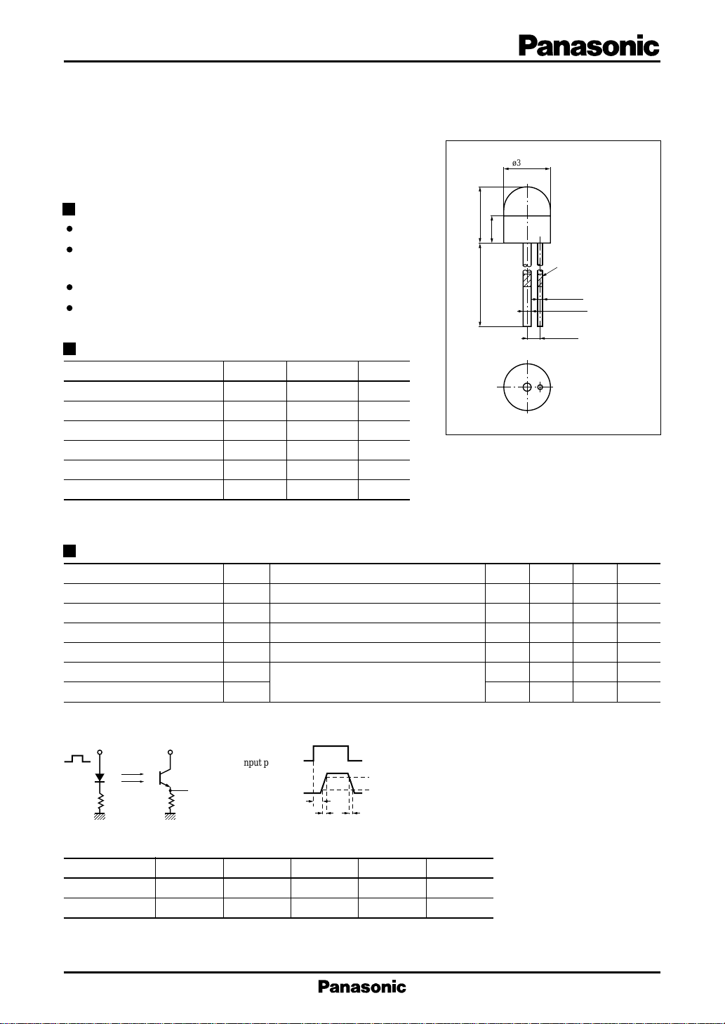
Silicon NPN Phototransistor
For optical control systems
ø3.0±0.2
Unit : mm
Features
High sensitivity
Good collector photo current linearity with respect to optical
power input
Fast response : tr = 2.5 µs (typ.)
Small size (ø 3) ceramic package
4.1±0.3
2.0±0.2
12.5 min.
Absolute Maximum Ratings (Ta = 25˚C)
Parameter Symbol Ratings Unit
Collector to emitter voltage
Emitter to collector voltage
Collector current I
Collector power dissipation
Operating ambient temperature
Storage temperature T
V
CEO
V
ECO
C
P
C
T
opr
stg
20 V
5V
20 mA
50 mW
–25 to +85 ˚C
–30 to +100 ˚C
Electro-Optical Characteristics (Ta = 25˚C)
Parameter Symbol Conditions min typ max Unit
Dark current I
Collector photo current I
Peak sensitivity wavelength
CEO
CE(L)
λ
Acceptance half angle θ
Rise time t
Fall time t
*1
Measurements were made using a tungsten lamp (color temperature T = 2856K) as a light source.
*2
Switching time measurement circuit
Sig.IN
50Ω R
V
CC
Sig.OUT 10%
L
(Input pulse)
(Output pulse)
VCE = 10V 1 100 nA
*3
VCE = 10V, L = 1000 lx
VCE = 10V 800 nm
P
*1
1050 2560 µA
Measured from the optical axis to the half power point
*2
r
*2
f
VCC = 10V, I
t
d
t
r
= 1mA, RL = 100Ω
CE(L)
td : Delay time
: Rise time (Time required for the collector photo current to
t
90%
r
increase from 10% to 90% of its final value)
: Fall time (Time required for the collector photo current to
t
t
f
f
decrease from 90% to 10% of its initial value)
Color indication I
ø0.3±0.05
ø0.45±0.05
0.9±0.15
1
2
30 deg.
2.5 µs
3.5 µs
rank
CE(L)
1: Emitter
2: Collector
*3
I
Classifications
CE(L)
Class Q R S T U
I
(µA) 1050 to1350 1260 to 1580 1480 to 1860 1730 to 2180 2030 to 2560
CE(L)
Color indication Brown Yellow Pink Black Red
1
Phototransistors PNZ126S
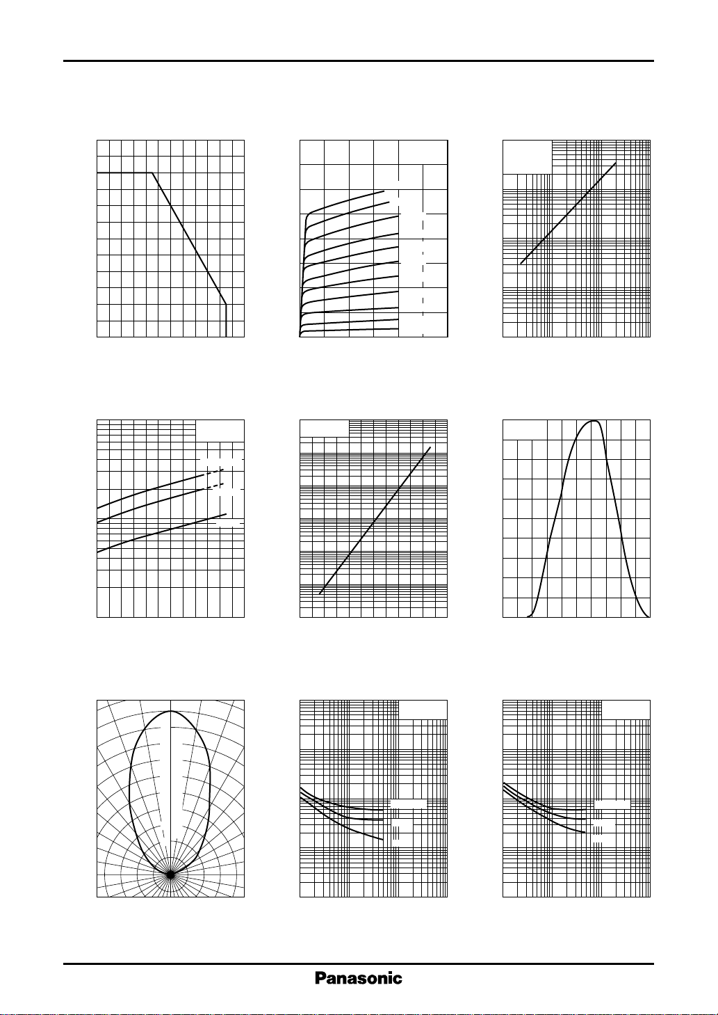
P
— Ta
60
50
(mW)
C
40
30
20
10
Collector power dissipation P
0
– 20
C
0 20406080100
Ambient temperature Ta (˚C )
I
— Ta
4
10
CE(L)
(µA)
CE(L)
3
10
Collector photo current I
VCE = 10V
T = 2856K
L = 1500 lx
1000 lx
500 lx
I
— V
CE(L)
L =2000 lx
1800 lx
(mA)
CE(L)
4
3
2
1
Collector photo current I
0
02010 30
Collector to emitter voltage VCE (V)
I
— Ta
10
10
10
(nA)
CEO
4
3
2
10
1
CEO
VCE = 10V
Dark current I
–1
10
CE
Ta = 25˚C
T = 2856K
1600 lx
1400 lx
1200 lx
1000 lx
800 lx
600 lx
400 lx
200 lx
100 lx
I
— L
V
= 10V
CE
Ta = 25˚C
T = 2856K
CE(L)
(µA)
CE(L)
4
10
3
10
2
10
10
Collector photo current I
1
10
2
10
3
10
Illuminance L (lx)
Spectral sensitivity characteristics
100
Ta = 25˚C
80
60
40
Relative sensitivity S (%)
20
4
10
2
10
– 20 0 40 8020 60 100
Ambient temperature Ta (˚C )
Directivity characteristics
0˚ 10˚ 20˚
100
90
80
70
60
50
40
30
Relative sensitivity S (%)
20
2
30˚
40˚
50˚
60˚
70˚
80˚
90˚
–2
10
– 20 0 40 8020 60 100
Ambient temperature Ta (˚C )
t
— I
r
3
10
2
10
(µs)
r
10
Rise time t
1
–1
10
–1
10
Collector photo current I
CE(L)
VCC = 10V
Ta = 25˚C
RL = 1kΩ
500Ω
100Ω
11010
CE(L)
(mA)
2
0
400 600 800 1000 1200
200
Wavelength λ (nm)
t
3
10
2
10
(µs)
f
10
Fall time t
1
–1
10
–1
10
Collector photo current I
— I
f
CE(L)
VCC = 10V
Ta = 25˚C
RL = 1kΩ
500Ω
100Ω
11010
CE(L)
2
(mA)
 Loading...