

Panasonic PNA4601M, PNA4602M, PNA4608M, PNA4610M Datasheet
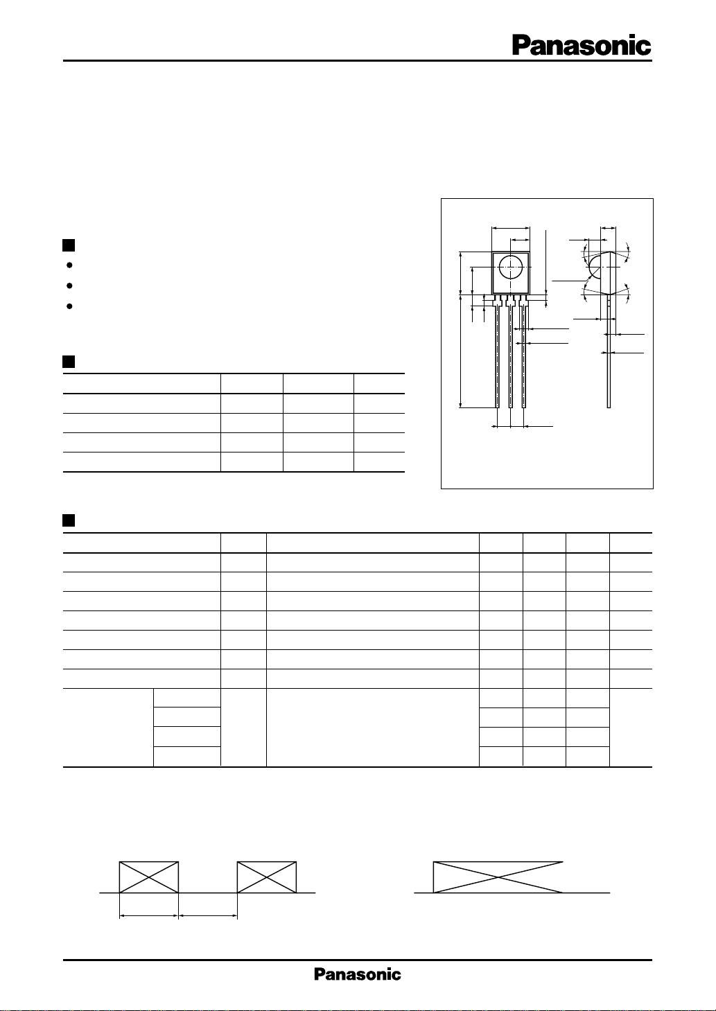
Photo IC
PNA4601M Series
(PNA4601M/4602M/4608M/4610M)
Bipolar Integrated Circuit with Photodetection Function
For infrared remote control systems
Features
Extension distance is 8 m or more
External parts not required
Adoption of visible light cutoff resin
Absolute Maximum Ratings (Ta = 25˚C)
Parameter Symbol Ratings Unit
Power supply voltage V
Power dissipation P
Operating ambient temperature
Storage temperature T
T
– 0.5 to +7 V
CC
D
–20 to +75 ˚C
opr
– 40 to +100 ˚C
stg
Main Characteristics (Ta = 25˚C VCC = 5V)
Parameter Symbol Conditions min typ max Unit
Operating supply voltage V
Current consumption I
Maximum reception distance
Low-level output voltage V
High-level output voltage V
Low-level pulse width T
High-level pulse width T
PNA4601M 36.7
Carrier frequency
PNA4602M
PNA4608M 56.9
PNA4610M 33.3
Note 1) Fig. 1 burst wave, L = L
Note 2) Fig. 2 continuous wave, L ≤ L
Note 3) Light shut off condition
L
, 16 pulses
max
CC
Note 3 1.8 2.4 3.0 mA
CC
Note 1 8 10 m
max
Note 2 0.35 0.5 V
OL
Note 3 4.8 5.0 V
OH
Note 1 200 400 600 µs
WL
Note 1 200 400 600 µs
WH
f
0
max
200 mW
7.0±0.2
3.5
8.0±0.2
5.2
2.3
22.0 min.
0.8
123
R2.25±0.1
Not soldered 1.5
3-1.5±0.2
3-0.5
2-2.54
4.7 5.0 5.3 V
38.0
+0.2
–0.15
2.25
2.0±0.1
5˚
5˚
CC
Unit : mm
5.25±0.3
5˚
5˚
1.0±0.1
0.45±0.2
1: V
OUT
2: GND
3: V
CC
V
kHz
Carrier wave : f
400µs
400µs
0
Carrier wave : f
0
Fig.2Fig.1
1
PNA4601M, PNA4602M, PNA4608M, PNA4610M Photo IC
Block Diagram
PD
AGC
constant voltage
B.P.F demodulatoramplifier
peak hold
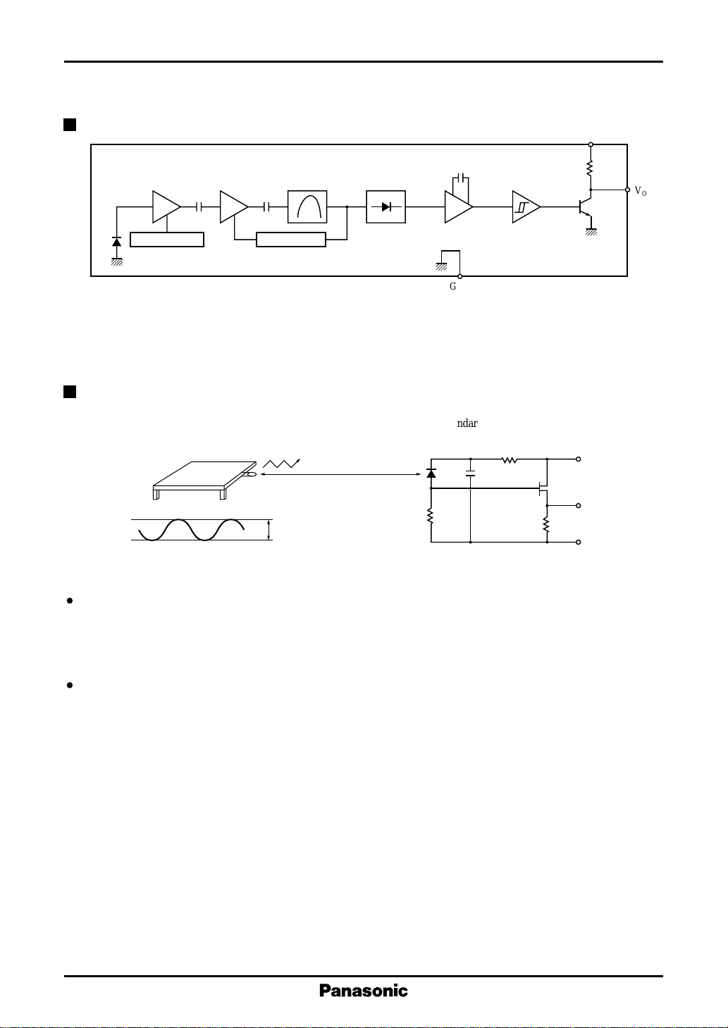
Panasonic Transmitter Specifications
LED Transmission unit
V out 55mV
20cm
PNZ323B
10kΩ
comparator
integrator
GND
Standard reception unit
10kΩ
10µF
10kΩ
(20kΩ)
V
CC
10V
V out
GND
R
L
V
O
The light output of the LED transmission unit is adjusted so that the transmission output (V out) of the standard
reception unit will be 55 mV when the transmission waveform (duty = 50%) is output from the LED transmission unit. Here, infrared sensitivity (SIR) of PNZ323B is 0.53 µA when emission illuminance (H) is 12.45 µW/
2
.
cm
The maximum reception distance under these specifications is an assurance that TWH and TWL values will be
within the tolerance ranges when 16 consecutive pulses of an optical output equivalent to the maximum reception distance are transmitted by the above transmission unit (The maximum reception distance is measured in
the dark without external disturbance noise.)
2
 Loading...