

Panasonic Switch-M48eG, PN28480K-TH, PN28480K-MY, PN28480K-ID Operation Manual
1
Thank you for purchasing our product.
This manual provides important information about safe and proper
operations of this Switching Hub.
Please read the "Important Safety Instruction" on pages 3 to 5.
Any problems or damage resulting from disassembly of this Switching
Hub by customers are not covered by the warranty.
Switch-M48eG
Model Number: PN28480K
Operation Manual
Menu Screens

2
This operation manual is applicable to the following Switching Hubs:
Product name Model No. Firmware version
Switch-M48eG PN28480K-ID
PN28480K-TH
PN28480K-MY
2.0.0.01 or higher
3
Important Safety Instructions
This chapter contains important safety instructions for preventing bodily
injury and/or property damage. You are required to follow them.
Severity of bodily injury and/or property damage, which could result from
incorrect use of the Switching Hub, are explained below.
The following symbols are used to classify and describe the type of
instructions to be observed.
This symbol is used to alert
users to what they must not do.
Do not use power supply other than AC 100 - 240V.
Deviation could lead to fire, electric shock, and/or equipment failure.
Do not handle the power cord with wet hand.
Deviation could lead to electric shock and/or equipment failure.
Do not handle this Switching Hub and connection cables during a
thunderstorm.
Deviation could lead to electric shock.
Do not disassemble and/or modify this Switching Hub.
Deviation could lead to fire, electric shock, and/or equipment failure.
Do not damage the power cord. Do not bend too tightly, stretch,
twist, bundle with other cord, pinch, put under a heavy object, and/or
heat it.
Damaged power cord could lead to fire, short, and/or electric shock.
Do not put foreign objects (such as metal and combustible) into the
opening (such as twisted pair port, console port, SFP extension slot),
and/or do not drop them into the inside of the Switching Hub.
Deviation could lead to fire, electric shock, and/or equipment failure.
WARNING
This symbol indicates safety instructions.
Deviation from these instructions could lead
to bodily injury and/or property damage.
This symbol is used to alert
users to what they must do.
WARNING
This symbol indicates a potential hazard that
could result in serious injury or death.
CAUTION
4
Do not connect equipments other than
10BASE-T/100BASE-TX/1000BASE-T to twisted pair port.
Deviation could lead to fire, electric shock, and/or equipment failure.
Do not place this Switching Hub in harsh environment (such as near
water, high humid, and/or high dust).
Deviation could lead to fire, electric shock, and/or equipment failure.
Do not place this Switching Hub under direct sun light and/or high
temperature.
Deviation could lead to high internal temperature and fire.
Do not install this Switching Hub at the location with continuous
vibration or strong shock, or at the unstable location.
Deviation could lead to injury and/or equipment failure.
Do not install any module other than the separately sold SFP module
(PN54021K/PN54023K) to SFP extension slot.
Deviation could lead to fire, electric shock, and/or equipment failure.
Do not put this Switching Hub into fire.
Deviation could lead to explosion and/or fire.
Do not use the supplied power cord for anything other than this
product.
Deviation could lead to fire, electric shock, and/or equipment failure.
Do not place this Switching Hub under direct sun light and or high
temperature.
Deviation could lead to fire to high internal temperature and fire.
WARNING
5
WARNING
CAUTION
Use the bundled power cord (AC 100 – 240V specifications).
Deviation could lead to electric shock, malfunction, and/or
equipment failure.
Unplug the power cord in case of equipment failure.
Deviation, such as keeping connected for a long time, could lead to
fire.
Connect this Switching Hub to ground.
Deviation could lead to electric shock, malfunction, and/or
equipment failure.
Connect the power cord firmly to the power port.
Deviation could lead to electric fire, shock, and/or malfunction.
Unplug the power cord if the STATUS/ECO LED (Status/ECO mode)
blinks in orange (system fault).
Deviation, such as keeping connected for a long time, could lead to
fire.
Handle the Switching Hub carefully so that fingers or hands may not
be damaged by twisted pair port, SFP extension slot, console port, or
power cord hook block.

6
Basic Instructions for the Use of This
Product
For inspection and/or repair, consult the shop.
Use commercial power supply from a wall socket, which is close and easily
accessible to this Switching Hub.
Unplug the power cord when installing or moving this Switching Hub.
Unplug the power cord when cleaning this Switching Hub.
Use this Switching Hub within the specifications. Deviation could lead to
malfunction.
When connecting a cable, hold the Switching Hub firmly.
Do not put a floppy disk or a magnetic card near the rubber feet (with built-in
magnets). Otherwise, recorded content may be lost.
After installing this Switching Hub on an OA desk, do not move either without
dismounting it. Otherwise, the desk surface may be damaged.
Do not touch the metal terminal of the RJ45 connector, the modular plug of
connected twisted pair cable, or the metal terminal of the SFP extension slot.
Do not place charged objects in the proximity of them. Static electricity could
lead to equipment failure.
Do not put the modular plug of the connected twisted pair cable on objects
that can carry static charge, such as carpet. Do not place it in the proximity.
Static electricity could lead to equipment failure.
Do not put a strong shock, including dropping, to this Switching Hub.
Deviation could lead to equipment failure.
Before connecting a console cable to the console port, discharge static
electricity, for example by touching metal appliance (do not discharge by
touching this Switching Hub).
Do not store and/or use this Switching Hub in the environment with the
characteristics listed below.
(Store and/or use this Switching Hub in the environment in accordance with
the specification.)

7
High humidity. Possible spilled liquid (water).
Dusty. Possible static charge (such as carpet).
Under direct sunlight.
Possible condensation. High/low temperature exceeding the specifications
environment.
Strong vibration and/or strong shock.
Please use this Switching Hub in place with the ambient temperature is from 0
to 50°C.
Failure to meet the above conditions may result in fire, electric shock,
breakdown, and/or malfunction. Please take notice because such cases are
out of guarantee.
Additionally, do not cover the bent hole of this Switching Hub.
Deviation could lead to high internal temperature, equipment failure and/or
malfunction.
When stacking Switching Hubs, leave a minimum of 20 mm space between
them.
Operation is not guaranteed if a module other than the optional SFP
extension modules (PN54021K/PN54023K) is inserted into the SFP extension
slot. For the latest information about compatible SFP extension modules,
check our website.
1. Panasonic will not be liable for any damage resulting from the operation
not in accordance with this document or the loss of communications,
which may or may not be caused by failure and/or malfunction of this
product.
2. The contents described in this document may be changed without prior
notice.
3. For any question, please contact the shop where you purchased the
product.
* Brands and product names in this document are trademarks or registered
trademarks of their respective holders.

8
Table of Contents
Important Safety Instructions ................................................................................ 3
Basic Instructions for the Use of This Product ....................................................... 6
1. Product Outline ................................................................................................ 11
1.1. Features ...................................................................................................... 11
1.2. Accessories .................................................................................................. 13
1.3. Part Names ................................................................................................. 14
1.4. LED Behavior ............................................................................................... 15
1.4.1. LED Behavior at Start-up ...................................................................... 15
1.4.2. LED Behavior while Operating ............................................................. 15
1.4.3. Loop detection function ....................................................................... 18
1.5. LED Display Change Button........................................................................ 19
1.5.1. Setting LED Base Mode ........................................................................ 19
1.5.2. LED Display Switchover ......................................................................... 19
2. Installation ........................................................................................................ 21
2.1. Mounting to 19-inch Rack .......................................................................... 21
3. Connection ....................................................................................................... 22
3.1. Connection Using a Twisted Pair Port ........................................................ 22
3.2. Connection Using an SFP Extension Slot .................................................... 23
3.3. Connection to Power .................................................................................. 24
4. Configuration ................................................................................................... 25
4.1. Connecting via Console Port ...................................................................... 25
4.2. Login ........................................................................................................... 26
4.3. Basic Operations on the Screen .................................................................. 29
4.4. Main Menu ................................................................................................. 31
4.5. General Information Menu ........................................................................ 33
4.6. Basic Switch Configuration ......................................................................... 37
4.6.1. System Administration Configuration .................................................. 39
4.6.2. System IP Configuration ....................................................................... 41
4.6.3. SNMP Configuration ............................................................................. 45
4.6.4. Port Configuration Basic ....................................................................... 74
4.6.5. Port Configuration Extend ................................................................... 78
4.6.6. Port Configuration Power Saving ......................................................... 81
4.6.7. System Security Configuration ............................................................. 84
4.6.8. Forwarding Database ......................................................................... 101

9
4.6.9. Time Configuration ............................................................................. 107
4.6.10. ARP Table .......................................................................................... 110
4.6.11. NDP Table ......................................................................................... 112
4.7. Advanced Switch Configuration .............................................................. 114
4.7.1. VLAN Management ............................................................................ 116
4.7.2. Link Aggregation ................................................................................ 126
4.7.3. Port Monitoring Configuration Menu ................................................ 128
4.7.4. Access Control Configuration Menu .................................................. 130
4.7.5 Quality of Service Configuration ......................................................... 155
4.7.6. Storm Control Configuration Menu ................................................... 159
4.7.7 802.1X Port Based Access Control ....................................................... 161
4.7.8 Loop Detection Configuration Menu .................................................. 164
4.7.9. Port Group Configuration Menu ........................................................ 168
4.7.10. Digital Diagnostic Monitoring Menu ................................................ 175
4.7.11. Static Multicast Address .................................................................... 178
4.8. Statistics .................................................................................................... 180
4.9. Switch Tools Configuration ...................................................................... 185
4.9.1. TFTP Software Upgrade ..................................................................... 186
4.9.2. Configuration File Upload/Download ................................................ 189
4.9.3. System Reboot .................................................................................... 191
4.9.4. Exception Handler............................................................................... 193
4.9.5. Ping Execution .................................................................................... 195
4.9.5.a. IPv4 Ping Execution .......................................................................... 196
4.9.5.b. IPv6 Ping Execution ......................................................................... 198
4.9.6. System Log .......................................................................................... 200
4.9.7. Watch Dog Timer Menu ..................................................................... 207
4.10. Save Configuration to Flash ................................................................... 208
4.11. Command Line Interface (CLI) ............................................................... 210
4.12. Logout ..................................................................................................... 211
Appendix A. Specifications .............................................................................. 212
Appendix B. Easy IP Address Setup Function .................................................. 214
Appendix C. Example of Network Configuration using Loop Detection Function
and Its Precautions ............................................................................................. 215
Appendix D. MIB List ....................................................................................... 217
Troubleshooting ................................................................................................. 231
After-sales Service ............................................................................................... 232

10
11
1. Product Outline
Switch-M48eG is an all Giga bit Ethernet Switching Hub with management
function having 44 ports of 10/100/1000BASE-T and four pairs of
10/100/1000BASE-T port and SFP extension slot, one of which is selectable.
1.1. Features
Has wire-speed Layer 2 switching function.
Ports 1 to 44 are 10/100/1000BASE-T ports corresponding to auto
negotiation. Also their speed and communication mode can be switched
by configuration. Ports 45 to 48 can be used as a 10/100/1000BASE-T
port corresponding to auto negotiation or an SFP extension slot
exclusively. Also their speed and communication mode can be switched
by configuration.
All twisted pair ports support straight/cross cable auto sensing function.
Simply connect devices with straight cables, whether it is a terminal or a
network device.
(This function does not work if the port communication configuration is
set at Fixed or Link Aggregation. Ports 1 to 44 are set at MDI-X. (default))
Has a loop detection function, which notifies when a loop occurs with
the corresponding port LED and automatically shuts down the looped
port.
Has a loop detection history function, which notifies when a loop occurs
with the corresponding LED and enables a network administrator to
identify the looped port after the loop is removed.
VLAN function allows free grouping of up to 256 VLANs
Fanless design solves noise problem or fan failure.
Use of LED indicator switching button saves power consumption of LED
lamps.
The IEEE802.1p compatible QoS function is supported.
Has an Internet mansion function, which ensures security between each
door.
Power saving mode detects the connection status automatically and
saves power consumption to minimum.

12
Telnet and SSH functions facilitate remote setting change and
confirmation.
Standard MIB (MIB II, Bridge MIB, etc.) is supported, enabling remote
control by using the SNMP manager. (For details, refer to Appendix A
and Appendix C.)
Link aggregation function is supported. Aggregation can be manually
configured up to 8 ports.
Reboot timer function is supported, enabling auto reboot after a
scheduled time (24 hours or less).
Equipped with energy efficient Ethernet (EEE) conforming to IEEE802.3az
(LPI). When there is no data transmission at link up, the energy-saving
state automati- cally starts so that power consumption can be reduced
on each port.

13
1.2. Accessories
Please be sure to confirm the content. Please contact our distributor if any of
the contents are insufficient.
Quantity
Installation Guide (this document)……………………………………………………… 1
CD-ROM (PDF version of Operating Instructions) ………………………………… 1
Mounting bracket (for 19-inch rack)…………………………………………………… 2
Screws (for 19-inch rack)…………………………………………………………………… 4
Screws (for fixing the main unit and the mounting bracket) ………………… 8
Rubber foot …………………………………………………………………………………… 4
Power cord……………………………………………………………………………………… 1
[Optional accessories]
PN54021K 1000BASE-SX SFP Module
PN54023K 1000BASE-LX SFP Module
14
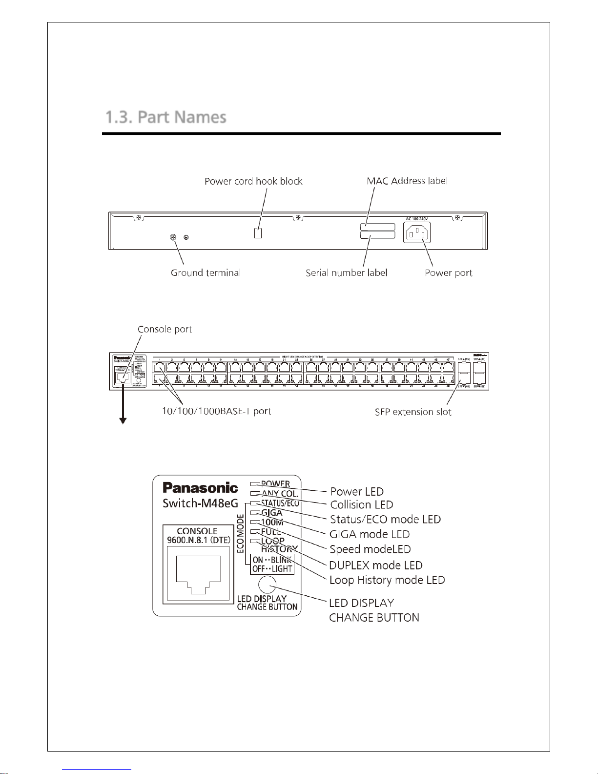
1.3. Part Names
Fig. 1-3 Part Names
Back panel
Magnified
Front panel
15
1.4. LED Behavior
1.4.1. LED Behavior at Start-up
Upon turning this Switching Hub on, all LEDs tentatively light up. Then, the
self-diagnosis of hardware is executed. Upon finishing the diagnosis, power
LED and status/ECO mode LED light in solid green. Then, the Switching Hub
starts working.
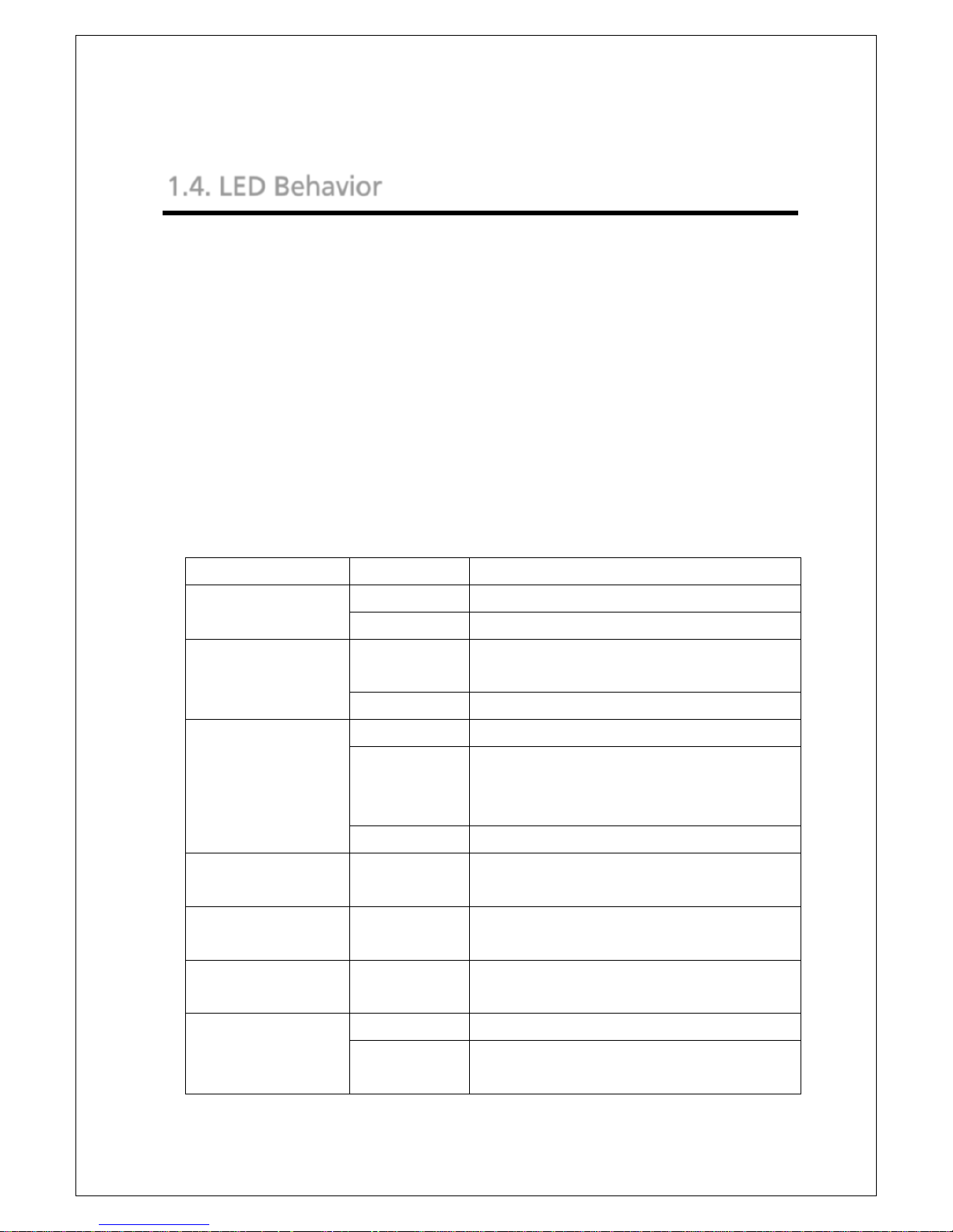
1.4.2. LED Behavior while Operating
This Switching Hub has a set of LEDs for each port. These LEDs indicate the
operation status of each port.
System LED
LED Behavior Description
POWER LED
(Power)
Green Light Power is ON.
Off Power is OFF.
ANY COL. LED
(Collision)
Orange Light During half-duplex operation, packet collision
is occurring in either port.
Off No packet collision.
STATUS/ECO LED
(Status/Eco mode)
Green Light Operating in status mode.
Green Blink Operating in ECO mode.
(All LEDs turn off, except POWER and
STATUS/ECO LEDs during ECO mode.)
Off Power is OFF.
GIGA LED
(GIGA mode)
Green Light
Operating in GIGA mode.
100M LED
(Speed mode)
Green Light
Operating in Speed mode.
FULL LED
(DUPLEX mode)
Green Light
Operating in Duplex mode.
LOOP HISTORY LED
(Loop History mode)
Green Light Operating in Loop history mode.
Green Blink Loop is occurring, or occurred within the last
3 days.

16
Port LED display mode LED
In the status mode described later, port LED shows linkup and
communication status. By pressing the LED display switch button in the front
panel, the display mode of port LED can be changed as follows.
Port LED display mode Description
STATUS/ECO Shows linkup and communication status.
GIGA Shows linkup status at 1000 Mbps.
100M Shows linkup status at 100 Mbps.
FULL Shows linkup status at full-duplex or half-duplex.
LOOP HISTORY Shows loop history and port shut-off status.
Port LED
According to switchover in the port LED display mode, described previously,
display of port LED in each port changes as follows.
Port LED Display mode Behavior Description
Left STATUS/ECO Green
Light
Link is established.
Green
Blink
Transmitting and receiving data.
Off No device connected.
GIGA Green
Light
Link is established at 1000 Mbps.
Off Link is established at 100 Mbps or 10
Mbps, or no device is connected.
100M Green
Light
Link is established at 100 Mbps.
Off Link is established at 1000 Mbps or 10
Mbps, or no device is connected.
FULL Green
Light
Link is established at full-duplex.
Off Link is established at half-duplex or no
device is connected.
LOOP HISTORY Green
Light
Within 3 days after loop removed.

17
Off No loop detection history.
Right
Orange
Light
Shutting down by loop detection.
Off Not shutting down by loop detection.
Fig. 1-4 Port LED

18
1.4.3. Loop detection function
Turns on the port LED with an orange light when a loop occurs in the
corresponding port. At this time, the relevant port automatically shuts down
(default setting: 60 sec.) to prevent loop from occurring. If the loop is still not
removed, the port will shut down again. Remove the loop while the port is
shut off.
The loop detection/shut-off function can be switched on/off by keeping
pressing the LED display switch button for more than 10 seconds or by
setting in the configuration menu. For details on the configuration menu,
refer to 4.7.8. If switching properly takes place, LOOP HISTORY LED turns on
to complete switchover.
The loop history can be reset by powering off the Switching Hub and then
on.
19
1.5. LED Display Change Button
1.5.1. Setting LED Base Mode
You can select display of LEDs in this Switching Hub from two types: Status
mode and Eco mode.
The mode selected at system start-up is called the base mode. The base mode
can be switched by keeping pressing the LED display switch button for more
than 3 seconds. After pressing the LED display switch button for more than 3
seconds, STATUS/ECO, GIGA, 100M, and FULL LEDs will turn on at once, and
then the mode will switch over.
Status mode (Factory default setting)
According to the port LED display mode, port LED shows the status of each
port. In status mode, STATUS/ECO LED lights in green.
ECO mode
Regardless of whether a device is connected or not,
all LEDs other than
POWER and STATUS/ECO LEDs turn off
to save power. In ECO mode,
STATUS/ECO LED flashes in green.
The base mode can be set from the configuration menu of this Switching
Hub. For details, refer to 4.6.7.h.
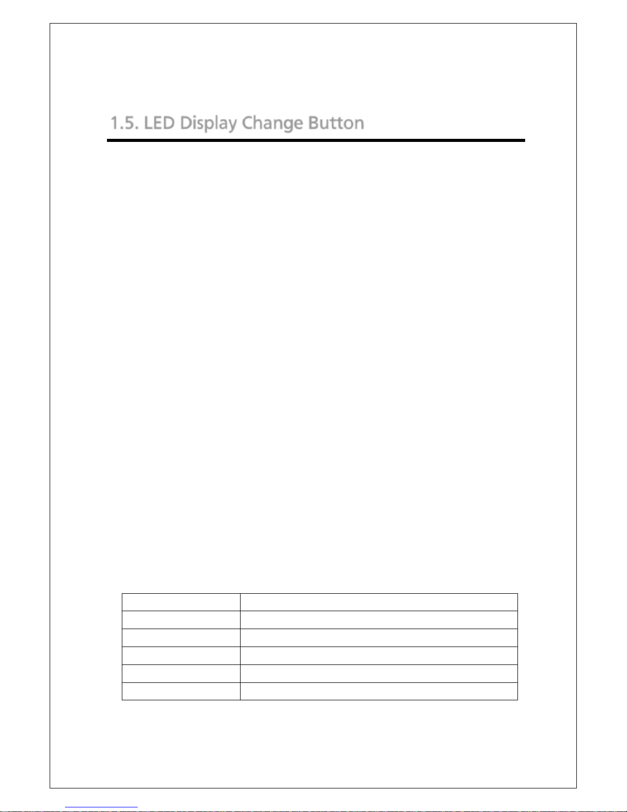
1.5.2. LED Display Switchover
By pressing the LED display switch button on the front panel, display of port
LED can be changed in the following order.
Port LED display mode Description
STATUS/ECO Shows link establishment and communication status.
GIGA Shows linkup status at 1000 Mbps.
100M Shows linkup status at 100 Mbps.
FULL Shows linkup status at full-duplex or half-duplex.
LOOP HISTORY Shows loop detection and port shut-off status.

20
If the port LED display mode is switched to other than STATUS/ECO and then
no operation is executed for more than 1 minute, the mode automatically
shifts to the base mode.
21
2. Installation
Switch-M48eG can be installed to a stainless steel product, a 19-inch rack, or
on the wall.
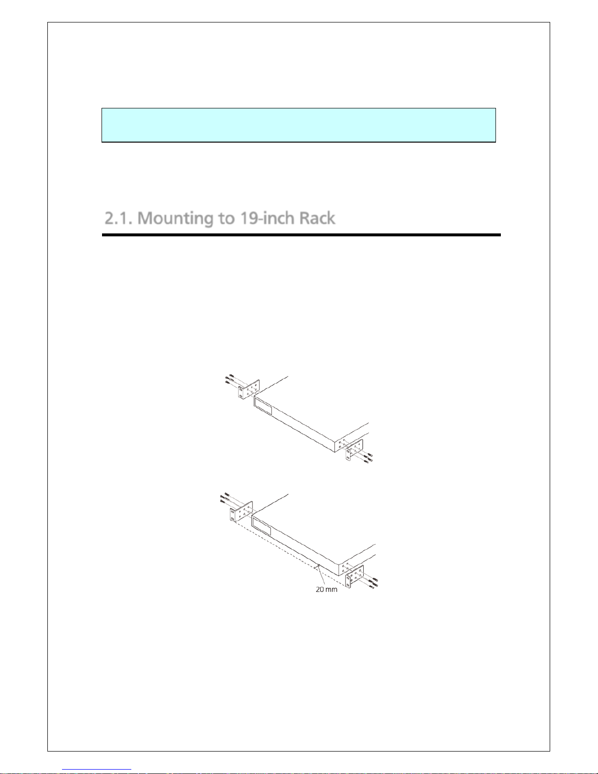
2.1. Mounting to 19-inch Rack
Take out the supplied 2 mounting brackets (for 19-inch rack) and 8 screws
(for fixing the main unit and the mounting bracket), and fix the brackets to
the main unit by tightening screws into 4 holes located at the sides. Then,
mount this Switching Hub firmly to the rack using the supplied 4 screws (for
19-inch rack) or screws furnished at the rack.
The main unit can be placed 20 mm back on the rack by changing the bracket
fixing position.
Fig. 2-1 Mounting to 19-inch Rack
22
3. Connection
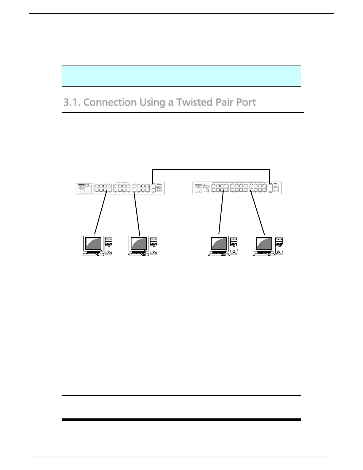
3.1. Connection Using a Twisted Pair Port
Connection Cable
Use a CAT5E or higher twisted pair cable with 8P8C RJ45 modular plug.
Network Configuration
Fig. 3-1 Example of Connection
The length of the cable connecting this Switching Hub and a device must be
100 m or shorter. When a terminal or a LAN device with auto negotiation
function is connected to this Switching Hub, the port is automatically
configured at the highest performance mode. When a terminal or a LAN
device without auto negotiation function is connected to this Switching Hub,
this Switching Hub automatically determines and sets the communication
speed; however, the full-duplex/half-duplex configuration is set at
half-duplex because the full-duplex/half-duplex capability cannot be
determined. When connecting a terminal or a LAN device without auto
negotiation function, a fixed-mode port configuration needs to be set.
Note: If a fixed-ode port configuration is set, Auto-MDI/MDI-X function
does not work. Therefore, use a cross cable to connect them.
100 m
or shorter
100 m
or shorter
100 m or shorter
23
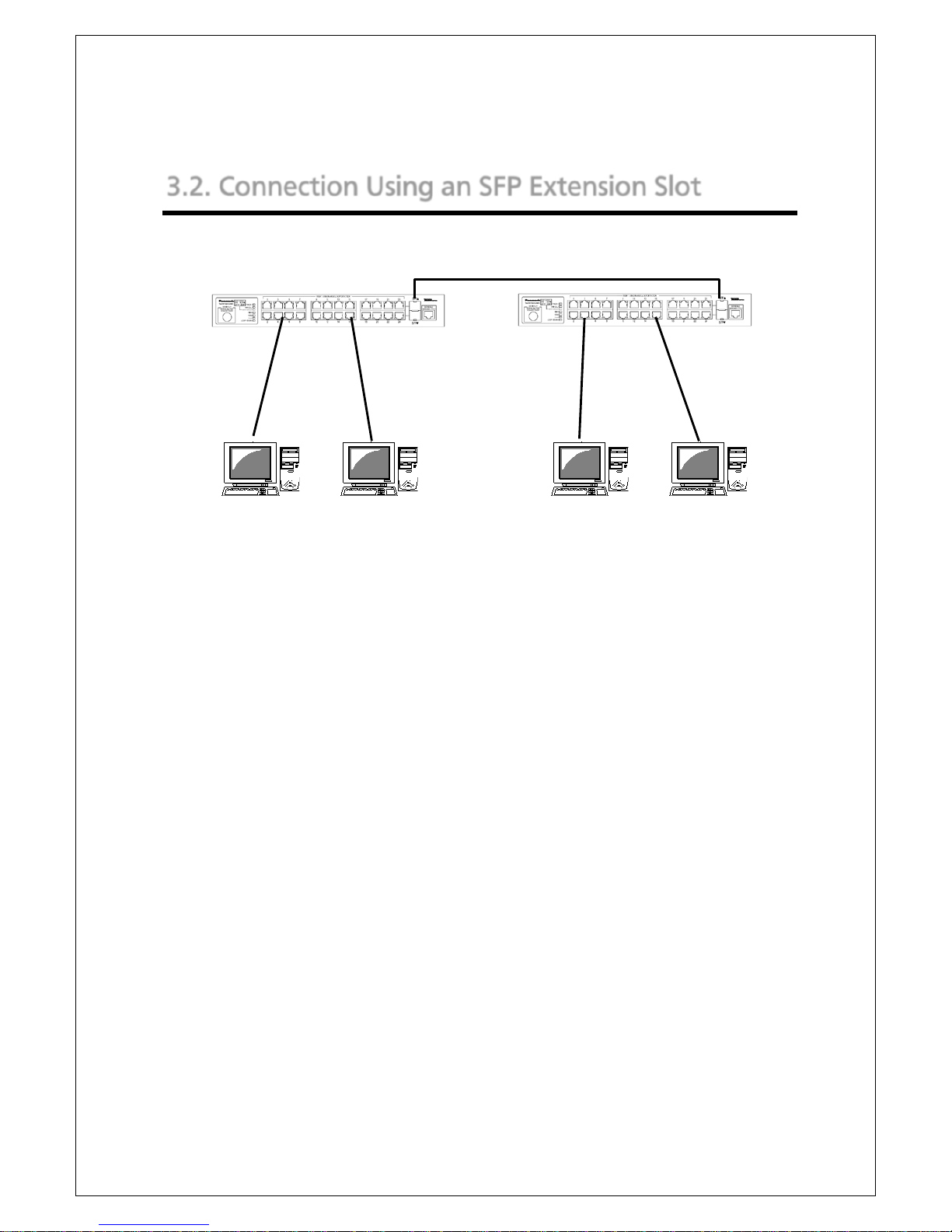
3.2. Connection Using an SFP Extension Slot
Fig. 3-2 Example of Optical Fiber Cable Connection
Plugging an SFP module (optional) into an SFP extension slot enables an
optical fiber connection. Connect this Switching Hub's TX port to the RX port
of the connected device and this Switching Hub's RX port to the TX port of
the connected device.
If a twisted pair cable and an SFP module are simultaneously connected to
combo ports that are used exclusively, SFP link has a priority.
1000BASE-SX: 550 m or shorter / 1000BASE-LX: 10 km or shorter
100 m
or shorter
100 m
or shorter

24
3.3. Connection to Power
Connect the supplied power code to the power port of this Switching Hub
and connect the other end into an electric outlet. This Switching Hub
operates at 100-240 V (50/60 Hz).
This Switching Hub does not have a power ON/OFF switch. Plugging the
power cord turns on this Switching Hub's power and the operation starts. To
power off, unplug the power code from the electric outlet.

25
4. Configuration
Upon power on, this Switching Hub starts working as a switching hub. To use
the SNMP management functionality or other unique functions, you need to
configure the Switching Hub using a console port, Telnet, or SSH.
In this chapter, the configuration of this Switching Hub is explained.
Note: You need to configure an IP address to access this Switching Hub via
Telnet or SSH. Therefore, configure an IP address first via the console
port, before accessing via Telnet or SSH.
4.1. Connecting via Console Port
Console connection requires a DEC VT100-compatible asynchronous terminal,
or a terminal capable of running a VT100-compatible terminal emulator,
such as HyperTerminal on Windows XP or older. Connect a terminal of this
kind to the console port of this Switching Hub.
Configure the communication mode for the asynchronous terminal as
follows:
Transmission mode: RS-232C (ITU-TS V.24 compatible)
Emulation mode: VT100
Transmission speed: 9600 bps
Data length: 8 bit
Stop bit: 1 bit
Parity control: None
Flow control: None

26
4.2. Login
If you access the Switching Hub via the console port, a screen shown in Fig.
4-2-1 appears.
If this screen does not appear, press Enter key to refresh the display or
confirm that there is no error in configuration of communication mode and
others.
Fig. 4-2-1 Login Screen (Console)
If accessing the Switching Hub via Telnet, a similar login screen appears,
displaying "Remote Management System Version" at the upper part of the
screen, as shown in Fig. 4-2-2.
==============================================================================
PN28480K Local Management System Version x.x.x.xx
MAC Address: xx:xx:xx:xx:xx:xx
==============================================================================
Login Menu
Login:

27
Fig. 4-2-2 Login Screen (Telnet)
==============================================================================
PN28480K Remote Management System Version x.x.x.xx
MAC Address: xx:x:xx:xx:xx:xx
==============================================================================
Login Menu
Login:

28
On the screens in Fig. 4-2-1 and Fig. 4-2-2, enter the login name and
password. First, enter the login name. The Switching Hub's default login
name is set to "manager." Enter "manager" and press the Enter key. Then,
you need to enter a password, as shown in Fig. 4-2-3. The Switching Hub's
default password is the same as the login name ("manager"). Enter the
password correctly and press the Enter key.
Fig. 4-2-3 Entering Password
Both the login name and password can be changed. For the detailed change
procedure, refer to 4.6.7.
Note: A password is displayed with asterisks (*) as a user enters it.
Note: Up to four users can access the Switching Hub concurrently via Telnet,
and two users via SSH.
Note: Follow the operating procedures for SSH client to login via SSH.
==============================================================================
PN28480K Local Management System Version x.x.x.xx
MAC Address: xx:xx:xx:xx:xx:xx
==============================================================================
Login Menu
Login: manager
Password: *******
29
4.3. Basic Operations on the Screen
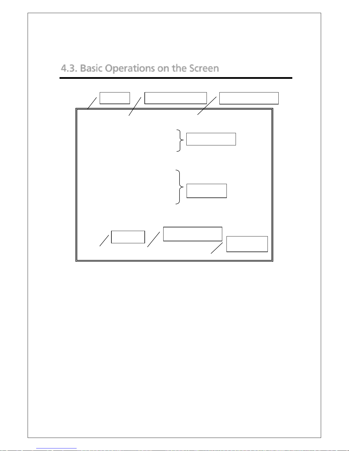
The console screen of the Switching Hub is organized as follows:
Fig. 4-3-1 Screen Structure
PN28480K Local Management System
Basic Switch Configuration -> System IP Configuration Menu
MAC Address: xx:xx:xx:xx:xx:xx
IP Address: 192.168.1.10
Subnet Mask: 255.255.255.0
Default Gateway: 0.0.0.0
-------------------------------- <COMMAND> -----------------------------------
Set [I]P Address
Set Subnet [M]ask
Set Default [G]ateway
Set IP P[a]rameter
Set I[P]v6 Address
[Q]uit to previous menu
Command>
Enter the character in square brackets to select option
2. Previous menu name
1. Title
3. Current menu name
4. Configuration
6. Prompt
7. Command entry line
5. Command
8. Explanation

30
Screen Description
1. Title The title of this screen. Shows "Local Management
System" while being accessed via console. Shows
"Remote Management System" while being accessed via
Telnet.
2. Previous menu
name
Shows the name of the previous menu. Pressing "Q,"
described later, opens the menu screen shown in this
field.
3. Current menu
name
Shows the name of the current screen.
4. Configuration Shows the current configuration, set on this screen.
5. Command Shows the commands available on this screen. Available
commands differ on each screen. Select a command
from the list.
6. Prompt Changes as you enter a command, indicating what you
need to enter next. Follow the instruction in this field.
7. Command
entry line
Enter a command or settings.
8. Explanation Shows the explanation of this screen or errors.
All operations on this screen are done by entering letters. Using a cursor or
other operations are not available. A letter as a valid command is enclosed in
square brackets in the command section of each screen. If you enter an
invalid command or setting, an error message is shown in the explanation
field.
 Loading...