

Panasonic PN28058, PN28088, PN28128, PN28168, PN28248 Operation Manual For Cli
Operation
Manual
for CLI
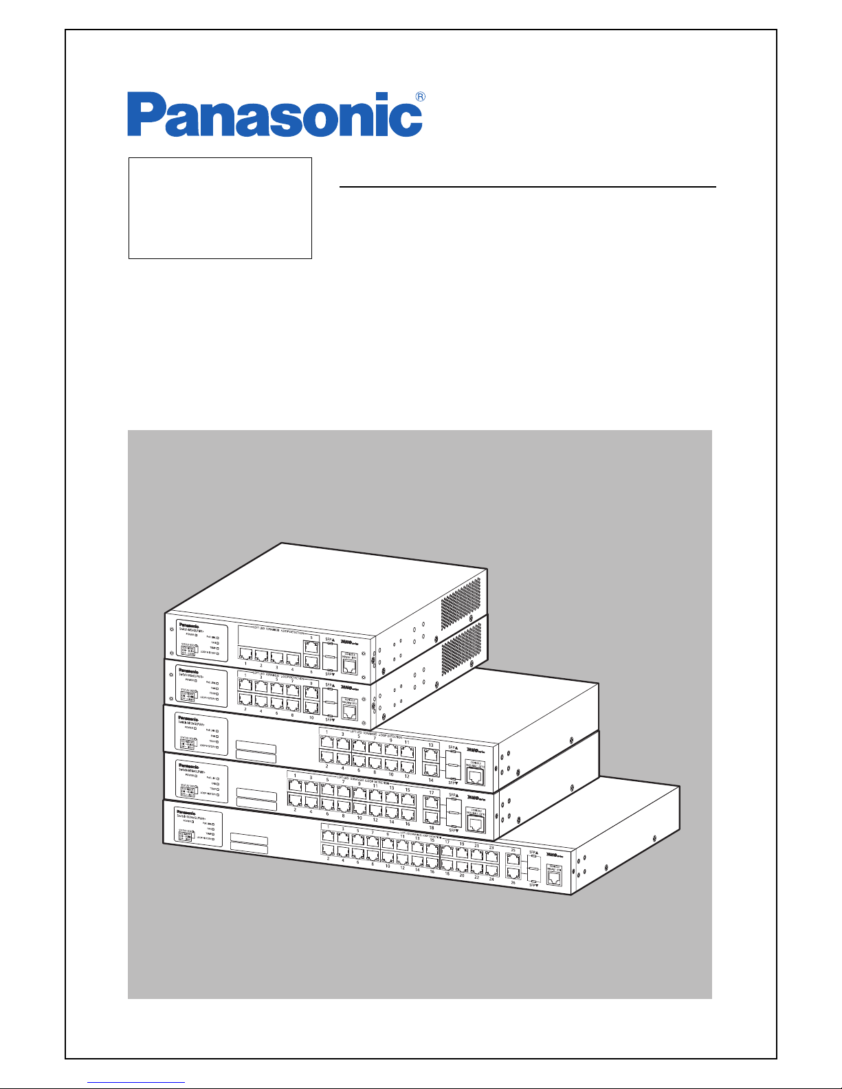
Layer 2 Switching Hub
Model Number: PN28058/PN28088
/PN28128/PN28168/PN28248
Thankyouforpurchasingourproduct.
Thismanualprovidesimportantinformationaboutsafeandproperoperations
ofthisswitch.
Pleaseread"ImportantSafetyInstructions"onpages3to5beforeuse.
Fortargetmodelnamesandnumbers,refertothenextpage.
Underallcircumstances,customerdisassemblingofthisswitchvoidsthewar
-
ranty.

The target model for this Operation Manual is as follows.
Model name Model number Firmware version
Switch-M5eGLPWR+ PN28058-ID
PN28058-TH
PN28058-MY
PN28058-SG
1.0.0.02 and higher
Switch-M8eGLPWR+ PN28088-ID
PN28088-TH
PN28088-MY
PN28088-SG
1.0.0.02 and higher
Switch-M12eGLPWR+ PN28128-ID
PN28128-TH
PN28128-MY
PN28128-SG
1.0.0.02 and higher
Switch-M16eGLPWR+ PN28168-ID
PN28168-TH
PN28168-MY
PN28168-SG
1.0.0.02 and higher
Switch-M24eGLPWR+ PN28248-ID
PN28248-TH
PN28248-MY
PN28248-SG
1.0.0.04 and higher
2
Important Safety Instructions
Please Follow the Instructions
3
This chapter contains important safety instructions for preventing bodily injury
and/or property damage. You are required to follow them.
■Severi
ty of bodily injury and/or property damage, which could result from incor-
rect use of the switch, are explained below.
This symbol indicates a potential hazard that could result in
serious injury or death.
This symbol indicates safety instructions.Deviation from these
instructions could lead to bodily injury and/or property dam-
age.
■The following symbols are used to classify and describe the type of instructions to
be observed.
This symbol is used to alert
users to what they must not do.
This symbol is used to alert
users to what they must do.
●Do not use power other than AC 100-240 V.
Deviation could lead to fire, electric shock, and/or equipment fa
ilure.
●Do not handle the power cord with wet hand.
Deviation could lead to electric shock and/or equipment failure.
●Do not handle this switch and connection cables during a thunder
storm.
Deviation could lead to electric shock.
●Do not disassemble and/or modify this Switching Hub.
Deviation could lead to fire, electric shock, and/or equipment fa
ilure.
●Do not damage the power cord. Do not bend too tightly, stretch,
twist,
bundle with other cord, pinch, put under a heavy object, and/or
heat it.
Damaged the cord could lead to fire, short, and/or electric shock
.
●Do not put foreign objects (such as metal or combustibles) into
the
opening (such as twisted pair port, console port, SFP expansion slot),
and do not drop them inside the Switching Hub.
Deviation could lead to fire, electric shock, and/or equipment fa
ilure.
●Do not connect equipment other than
10BASE-T/100BASE-TX/1000BASE-T to
a twisted pair port.
Deviation could lead to fire, electric shock, and/or equipment fa
ilure.
●Do not please this Switching Hub in harsh environment(such as near
water, high humid, and/or high dust).
Deviation could lead to fire, electric shock, and/or equipment fa
ilure.
●Do not place this Switching Hub under direct sunlight and/or hig
h tem
-
perature.
Deviation could lead to high internal temperature and fire.
●Do not install this Switching Hub at a location with continuous
vibra
-
tion or strong shock, or at an unstable location.
The switch may fall off, leading to injury and/or equipment failu
re.
●Do not connect any cable other than our optional console cable.
Deviation could lead to fire, electric shock, and/or equipment failure.
●Do not put this switch into fire.
Deviation could lead to explosion and/or fire.
●Do not use the supplied power cord for anything other than this p
rod
-
uct.
Deviation could lead to fire, electric shock, and/or equipment fa
ilure.
●Do not insert any modules other than the optional SFP modules
(
PN54021K/PN54023K) into the SFP extension slot.
Deviation could lead to fire, electric shock, and/or equipment fa
ilure.
For the latest information about compatible SFP extension modules
,
check our website.
4
●Use the bundled power cord (AC 100 - 240V specifications).
Deviation could lead to electric shock, malfunction, and/or equip
ment
failure.The warranty does not cover any problems resulting from the use
of any power cord other than the one supplied.
●Unplug the power cord in case of equipment failure.
Deviation such as keeping connected for a long time could lead t
o fire.
●Connect this Switching Hub to ground.
Deviation could lead to electric shock, malfunction, and/or equip
ment
failure.
●Connect the power cord firmly to the power port.
Deviation could lead to electric fire, shock, and/or malfunction.
●Unplug the power cord if the Status/ECO LED (Status/ECO mode),
TEMP LED
(temperature sensor), blinks in orange (system fault).
Deviation, such as keeping connected for a long time, could lead
to
fire.
●When this Switching Hub is installed on wall surface, mount it f
irmly
so as not to drop dwon because of weight of the main body andconnection
cable.
Deviation could lead to injury and/or equipment failure.
●Up to two Switching Hubs can be connected by using the connection
brackets and connection bracket screws included with the optional
PN71052 19-inchrack mount brackets (for two units). Attach the connec
-
tion brackets to the connection bracket screw holes on the front a
nd
back panels to securely fix the Switching Hubs before installation
If the Switching Hubs are not fixed securely, they may fall, leading
to
injury and/or equipment failure.
●To connect a power receiving equipment supporting IEEE802.3at to
this
Switching Hub, use a cable rated Cat5e or higher.
Using other cables may result in heat generation, ignition, and/o
r
equipment failure.
5

6
Basic Instructions for the Use of This Product
●For inspection and/or repair, consult the retailer.
●Use commercial power supply from a wall socket, which is close and easily acces
-
sible to this Switching Hub.
●Unplug the power cord when installing or moving this Switching Hub.
●Unplug the power cord when cleaning this Switching Hub.
●Use this Switching Hub within the specifications. Deviation could lead to mal
-
function.
●When installing this Switching Hub using rubber feet (with built-in magnets),
confirm that it does not move or fall down due to weight of cables.
●When connecting a cable, hold the Switching Hub firmly.
●If you install this Switching Hub at a high place, securely fix it on the wall
with screws.
●If you install this Switching Hub at a high place with magnets alone, it may
fall, leading to injury or failure of this Switching Hub.
●Do not put a floppy disk or a magnetic card near the rubber feet (with built-in
magnets). Otherwise, recorded content may be lost.
●After installing this Switching Hub on an OA desk, do not move either without
dismounting it. Otherwise, the desk surface may be damaged.
●Do not touch the metal terminal of the RJ45 connector, the modular plug of con
-
nected twisted pair cable. Do not place charged objects in the proximity of them.
Static electricity could lead to equipment failure.
●Do not put the modular plug of the connected twisted pair cable on objects that
can carry static charge, such as carpet. Do not place it in the proximity. Static
electricity could lead to equipment failure.
●Do not put a strong shock, including dropping, to this Switching Hub. Deviation
could lead to equipment failure.
●Before connecting a console cable to the console port, discharge static electric
-
ity, for example by touching metal appliance (do not discharge by touching this
Switching Hub).

7
1. Panasonic will not be liable for any damage resulting from the operation not in
accordance with this operation manual, or loss of communications, which may or
may not be caused by failure and/or malfunction of this device.
2. The contents described in this document may be changed without prior notice.
3. For any questions, please contact your dealer.
* Brands and product names in this document are trademarks or registered trademarks
of their respective holders.
●Do not store and/or use this Switching Hub in the environment with the character
-
istics listed below.(Store and/or use this Switching Hub in the environment in
accordance with the specification.)
- High humidity. Possible spilled liquid (water).
- Dusty. Possible static charge (such as carpet).
- Under direct sunlight.
- Possible condensation. High/low temperature exceeding the specifications envi
-
ronment.
- Strong vibration and/or strong shock.
●Please use this Switching Hub in places where the ambient temperature is in the
range from 0 to 50 degrees C.
●Failure to satisfy the conditions above may result in a fire, electric shock,
equipment failure, and/or malfunction. Such events are not covered by the war
-
ranty. Do not block the ventilator of the Switching Hub. Blocked ventilator
induces the heat accumulation inside, causing equipment failure and/or malfunc
-
tion. If used at a temperature out of the operating temperature range, the pro
-
tection equipment becomes activated and PoE power supply stops.
●When using two Switching Hubs, do not stack them. When you place them side by
side, allow for a space of 20 mm or more between them. This space is not neces
-
sary if you use PN71052 connection brackets.
●Operation is not guaranteed if a module other than the optional SFP extension
modules (PN54021K/PN54023K) is inserted into the SFP extension slot. For the lat
-
est information about compatible SFP extension modules, check our website.
●When stacking Switching Hubs, leave a minimum of 20 mm space between them.

8
Table of Contents
Important Safety Instructions ................................................... 3
Basic Instructions for the Use of This Product .................................. 6
1. Command Hierarchy ........................................................ 10
2. Displaying Basic Information ............................................. 13
3. Basic Switch Configuration ............................................... 14
3.1. System Administration Configuration .................................... 14
3.2. IP Address Configuration ............................................... 16
3.3. SNMP Configuration ..................................................... 18
3.4. Port Configuration ..................................................... 21
3.5. Access Condition Configuration ......................................... 24
3.6. MAC Address Table Display and Registration Configuration ............... 28
3.7. SNTP Configuration ..................................................... 30
3.8. ARP Table Display and Registration Configuration ....................... 31
3.9. LLDP Configuration ..................................................... 32
4. Advanced Switch Configuration ............................................ 34
4.1. VLAN Configuration ..................................................... 34
4.2. Link Aggregation Configuration ......................................... 36
4.3. Port Monitoring Configuration .......................................... 37
4.4. Spanning Tree Configuration ............................................ 38
4.5. QoS (Quality of Service) Configuration ................................. 40
4.6. Bandwidth Control Configuration ........................................ 43
4.7. IEEE802.1X Port-Based Authentication Configuration ..................... 44
4.8. IGMP Snooping Configuration ............................................ 46
4.9. PoE Power Supply Function Configuration ................................ 49
4.9.1.PoE Scheduler Configuration ........................................ 50
4.10.Storm Control Configuration ............................................ 54
4.11.Ring Protocol Configuration ............................................ 55
4.12.Line Configuration ..................................................... 57
4.12.1.Loop Detection and Blocking Configuration ......................... 57
4.13.Displaying and Configuring SFP module status check function ............ 59
5. Displaying Statistic Information ......................................... 61
6. Transferring Configuration Files ......................................... 62
7. Firmware Upgrade ......................................................... 63
8. Reboot ................................................................... 64
9. Exception Handler ........................................................ 65
10. Ping Execution ........................................................... 66
11. Displaying and Configuring the System Log ................................ 67
12. Saving Configuration Information ......................................... 69
13. Displaying Configuration Information ..................................... 70
14. Obtaining Technical Support Information .................................. 71
Appendix.A. Specifications ..................................................... 72

9
Appendix.B. Easy IP Address Setup Function ..................................... 73
Appendix.C. Troubleshooting .................................................... 74
Appendix.D. After-sales Service ................................................ 75

10
1. Command Hierarchy
There are four hierarchical levels in the command hierarchy.
(1) User mode:
The User mode is the mode right after login. Only limited operations
are avail-
able.
(2) Privileged mode:
The Privileged mode allows to check the status of this switch an
d manipulate
the configuration file.
(3) Global configuration mode:
The Global configuration mode a
llows general configuration of this switch.
(4) Interface configuration mode
The Interface configuration mode allows detailed configuration o
f this switch,
such as for each port or VLAN.
M8eGLPWR+> enable
M8eGLPWR+# configure
M8eGLPWR+(config)# interface gi0/1
M8eGLPWR+(config-if)# exit
M8eGLPWR+(config)# exit
M8eGLPWR+#
Fig. 1-1 Command hierarchy
enable command
・ The enable command enables to move
from User mode to Privileged mode.
M8eGLPWR+> ・・・・・・・・・・・・・・・・・・・・・・ User mode
M8eGLPWR+> enable ・・・・・・・・・・・・・・・ User mode
⇒ Privileged mode
M8eGLPWR+# ・・・・・・・・・・・・・・・・・・・・・・ Privileged mode
M8elGPWR+# disable ・・・・・・・・・・・・・・・ Privileged mode
⇒User mode
M8eLGPWR+> ・・・・・・・・・・・・・・・・・・・・・・ User mode
disable command
・ The disable command enables to retur
n from Privileged mode to User mode.
M8eLGPWR+# ・・・・・・・・・・・・・・・・・・・・・・ Privileged mode
M8eLGPWR+# disable ・・・・・・・・・・・・・・・ Privileged mode
⇒User mode
M8eLGPWR+> ・・・・・・・・・・・・・・・・・・・・・・ User mode
configure command
・ The configure command enables to move from Privileged mode to G
lobal con-
figuration mode.

11
M8eGLPWR+# ・・・・・・・・・・・・・・・・・・・・・・ Privileged mode
M8eGLPWR+# configure ・・・・・・・・・・・・ Privileged mode
⇒ Global configuration mode
M8eGLPWR+(config)# ・・・・・・・・・・・・・・
Global configuration mode
interface command
・ The interface command enables to move from Global configuration
mode to
Interface configuration mode.
M8eGLPWR+(config)# ・・・・・・・・・・・・・・
Global configuration mode
M8eGLPWR+(config)# interface vlan
1 Global configuration mode
⇒Interface
configuration mode (vlan1)
M8eGLPWR+(config-if)# exit ・・・・・・・・ Interface configuration mode
⇒ Global configuration mode
M8eGLPWR+(config)# interface gigabitethernet0/1
・・・・・・・・・・・・・・・・・・・・・・・・・・・・・・・・・・・・・・ Global configuration mode
⇒Interface
configuration mode (interface1)
M8eGLPWR+(config-if)# ・・・・・・・・・・・・ Interface configuration mode
M8eGLPWR+(config)# ・・・・・・・・・・・・・・
Global configuration mode
exit command
・ The exit command enables to return to the previous mode.
M8eGLPWR+(config-if)# exit ・・・・・・・・ Interface configuration mode
⇒ Global configuration mode
M8eGLPWR+(config)# exit ・・・・・・・・・・ Global configuration mode
⇒ Privileged mode
M8eGLPWR+# exit ・・・・・・・・・・・・・・・・・・ Privileged mode
⇒User mode
M8eGLPWR+> ・・・・・・・・・・・・・・・・・・・・・・ User mode
end command
・ The end command enables to move
from configuration modes to Privileged
mode.
M8eGLPWR+(config-if)# end ・・・・・・・・
Interface configuration mode
⇒ Privileged mode
M8eGLPWR+# config
M8eGLPWR+(config)# end ・・・・・・・・・・ Global configuration mode
⇒ Privileged mode
? command
・ Entering a question mark (?) in
each mode displays executable elements in the
mode.
M8eGLPWR+> ?
enable - Turn on privileged mode command
exit - Exit current mode and down to previous mode
logout - To logout from the CLI shell
ping - Send ICMP ECHO_REQUEST to network hosts
M8eGLPWR+>
Fig. 1-2 ? Command

12
Re-entry assist
・ Entering the up arrow key displays
a command that was entered immediately
before.
Candidate assist command
・ Entering a command followed by a question mark (?) displays candidat
es of suc-
ceeding arguments.
M8eGLPWR+# configure
M8eGLPWR+(config)# ip address
A.B.C.D - IP address (e.g. 10.0.0.1)
M8eGLPWR+(config)# ip address
Fig. 1-3 Candidate assist command
Command autocomplete
For command and argument entries, when
a word can be uniquely identified after
typing the first few letters, you can omit the remaining letters.
[Autocomplete examples]
・enable → en
・ show running-config → sh ru
[Example when autocomplete does not work]
・ co → Typing "co" does not run autocomplete because there are tw
o candidates
"configure" and "copy."
Meanings of symbols in descriptions are as follows:
< > : Required - Make sure t
o enter this item.
{ | } : Choice - Select and enter either one.
[ ] : Optional - Enter as necessary.

13
2. Displaying Basic Information
Enter "show sys-info" in "Privileged mode" to view the basic information of this
switch as shown in Fig. 2-1.
Basic information display command
Privileged mode show sys-info
M8eGLPWR+# show sys-info
System up for : xxxday(s), xxhr(s), xxmin(s), xxsec(s)
Boot / Runtime Code Version: x.x.x.xx / x.x.x.xx
Hardware Information
Version : Version1
CPU Utilization : xx.xx %
DRAM / Flash Size : 64MB / 8MB
DRAM User Area Size : Free: xxxxxxxx bytes / Total: xxxxxxxx bytes
System Temperature : CPU/xx ,System/xx degree(s) Celsius
Administration Information
Switch Name :
Switch Location :
Switch Contact :
System Address Information
MAC Address : xx:xx:xx:xx:xx:xx
IP Address : 0.0.0.0
Subnet Mask : 0.0.0.0
Default Gateway : 0.0.0.0
DHCP Mode : Disabled
M8eGLPWR+#
Fig. 2-1 Displayingbasicinformation
(showsys-info)

14
3. Basic Switch Configuration
3.1. System Administration Configuration
Configure the host name, installation location and contact information in "Global
configuration mode." Confirm the configuration information by entering "show
sys-info" in "Privileged mode."
Host name configuration command
Global configuration mode hostname <hostname>
Host name delete command
Global configuration mode no hostname
Installation location configuration command
Global configuration mode snmp-server location <server location>
Installation location delete command
Global configuration mode no snmp-server location
Contact information configuration command
Global configuration mode snmp-server contact <server contact>
Contact information delete command
Global configuration mode no snmp-server contact
Basic information display command
Privileged mode show sys-info
Note: When configuring a host name containing a space, enter it embracing with
double quotation marks (" ").
Example: hostname "Switch 1"

15
Example: Configuration example of the host name as PoESW-1, installation location as Office-2F, and contact infor
mation as Manager
M8eGLPWR+>
M8eGLPWR+> enable
M8eGLPWR+# configure
M8eGLPWR+(config)# hostname PoESW-1
PoESW-1(config)# snmp-server location Office-2F
PoESW-1(config)# snmp-server contact Manager
PoESW-1(config)# end
PoESW-1# show sys-info
System up for : 000day(s), 00hr(s), 00min(s), 00sec(s)
Boot / Runtime Code Version: x.x.x.xx / x.x.x.xx
Hardware Information
Version : Version1
CPU Utilization : xx.xx %
DRAM / Flash Size : 64MB / 8MB
DRAM User Area Size : Free: xxxxxxxx bytes / Total: xxxxxxxx bytes
System Temperature : CPU/xx ,System/xx degree(s) Celsius
Administration Information
Switch Name : PoESW-1
Switch Location : Office-2F
Switch Contact : Manager
System Address Information
MAC Address : xx:xx:xx:xx:xx:xx
IP Address : 192.168.0.1
Subnet Mask : 255.255.255.0
Default Gateway : 192.168.1.254
DHCP Mode : Disabled
PoESW-1#
Fig. 3-1 Display of the host name, installation location and contact information con
-
figuration (show sys-info)

16
3.2. IP Address Configuration
Configure the IP address settings of this switch in "Interface configuration mode."
Confirm the configuration information by entering "show ip conf" in "Privileged
mode."
IP address configuration command
Global configuration mode ip address
<ip-address> <mask> [<default-gateway>]
Default gateway configuration command
Global configuration mode ip default-gateway <ip-address>
DHCP client configuration command
Global configuration mode ip address dhcp
DHCP address reacquisition command
Global configuration mode ip address renew
DHCP client configuration disable command
Global configuration mode no ip address dhcp
IP address display command
Privileged mode show ip conf
Example 1: Configuration example of IP address as 192.168.0.1, subnet mask as
255.255.255.0, and default gateway as 192.168.0.254
M8eGLPWR+> enable
M8eGLPWR+# configure
M8eGLPWR+(config)# ip address 192.168.0.1 255.255.255.0
M8eGLPWR+(config)# ip default-gateway 192.168.0.254
M8eGLPWR+(config)# end
M8eGLPWR+# show ip conf
MAC Address : xx:xx:xx:xx:xx:xx
IP Address : 192.168.0.1
Subnet Mask : 255.255.255.0
Default Gateway : 192.168.0.254
DHCP Mode : Disabled
M8eGLPWR+#
Fig. 3-2 Display of the IP address configuration
(show ip conf)

17
Example 2. Configuration example of DHCP client
M8eGLPWR+> enable
M8eGLPWR+# configure
M8eGLPWR+(config)# ip address dhcp
M8eGLPWR+(config)# end
M8eGLPWR+# show ip conf
MAC Address : xx:xx:xx:xx:xx:xx
IP Address : 0.0.0.0
Subnet Mask : 0.0.0.0
Default Gateway : 0.0.0.0
DHCP Mode : Enabled
M8eGLPWR+#
Fig. 3-3 Display of the DHCP client and IP address configuration
(show ip conf)
Note: Unless you configure these settings, you cannot use the SNMP management
functions and remotely connect to the switch via Telnet, SSH or the web man
-
agement function. Be sure to configure. If you are unsure of the
settings, con-
sult the network administrator. Any IP addresses on the local ne
twork must
be unique, and no duplication is allowed. In addition, you need to set the subnet mask and the default gateway, which are the same for other d
evices on
the same subnet using this switch.

18
3.3. SNMP Configuration
Configure the SNMP agent setting in "Global configuration mode." Confirm the
configuration information by entering "show snmp" in "Privileged mode."
SNMP enable command
SNMP disable command
SNMP administration (read only or read/write configuration) command
SNMP administration configuration delete command
SNMP trap (type, IP address, community name) configuration command
SNMP trap configuration delete command
SNMP trap (authentication failure) configuration command
SNMP trap (authentication failure) delete command
SNMP trap (link-down port) configuration command
SNMP trap (link-down port) delete command
SNMP trap (PoE supply operation) configuration command
SNMP trap (PoE supply operation) delete command
SNMP trap (FAN error detection) configuration command
SNMP trap (FAN error detection) delete command
SNMP trap (temperature detection) enable command
SNMP trap (temperature detection) disable command
Global configuration mode snmp-server agent
Global configuration mode no snmp-server agent
Global configuration mode snmp-server community <index> <community> {RO|RW}
[<ip>]
Global configuration mode no snmp-server community <index>
Global configuration mode snmp-server host <index> type {v1|v2} <ip> trap <commu
-
nity>
Global configuration mode no snmp-server host <index>
Global configuration mode snmp-server enable traps snmp authentication
Global configuration mode no snmp-server enable traps snmp authentication
Global configuration mode snmp-server enable traps linkupdown <1-2 or 1,2,3 or
1,2,3-5>
Global configuration mode no snmp-server enable traps linkupdown <1-2 or 1,2,3 or
1,2,3-5> }
Global configuration mode snmp-server enable traps poe
Global configuration mode no snmp-server enable traps poe
Global configuration mode snmp-server enable traps fan-fail
Global configuration mode no snmp-server enable traps fan-fail
Global configuration mode snmp-server enable traps temperature-control
Global configuration mode no snmp-server enable traps temperature-control

19
SNMP trap (temperature detection) temperature configuration command
SNMP trap (ddm) enable command
SNMP trap (ddm) disable command
SNMP display command
Example 1: Configuration example of SNMP agent, SNMP manager, tr
ap receiver,
and various traps
M8eGLPWR+> enable
M8eGLPWR+# configure
M8eGLPWR+(config)# snmp-server agent
M8eGLPWR+(config)# snmp-server community 1 private rw 192.168.1.200
M8eGLPWR+(config)# snmp-server community 2 public ro 192.168.1.200
M8eGLPWR+(config)# snmp-server host 1 type v1 192.168.1.200 trap public
M8eGLPWR+(config)# snmp-server enable traps snmp authentication
M8eGLPWR+(config)# snmp-server enable traps linkupdown 1-10
M8eGLPWR+(config)# snmp-server enable traps poe
M8eGLPWR+(config)# snmp-server enable traps fan-fail
M8eGLPWR+(config)# snmp-server enable traps temperature-control
M8eGLPWR+(config)# snmp-server enable traps temperature-threshold 39
M8eGLPWR+(config)# end
M8eGLPWR+#
Fig. 3-4 SNMP configuration
Global configuration mode snmp-server enable traps temperature-threshold
< temperature >
Global configuration mode snmp-server enable traps ddm
Global configuration mode no snmp-server enable traps ddm
Privileged mode show snmp

M8eGLPWR+# show snmp
SNMP Agent: Enabled
SNMP Manager List:
No. Status Privilege IP Address Community
---- -------- ----------- --------------- --------------------------- 1 Enabled Read-Write 192.168.1.200 private
2 Enabled Read-Only 192.168.1.200 public
3 Disabled Read-Only 0.0.0.0
4 Disabled Read-Only 0.0.0.0
5 Disabled Read-Only 0.0.0.0
6 Disabled Read-Only 0.0.0.0
7 Disabled Read-Only 0.0.0.0
8 Disabled Read-Only 0.0.0.0
9 Disabled Read-Only 0.0.0.0
10 Disabled Read-Only 0.0.0.0
Trap Receiver List:
No. Status Type IP Address Community
---- -------- ----------- --------------- --------------------------- 1 Enabled v1 192.168.1.200 public
2 Disabled v1 0.0.0.0
3 Disabled v1 0.0.0.0
4 Disabled v1 0.0.0.0
5 Disabled v1 0.0.0.0
6 Disabled v1 0.0.0.0
7 Disabled v1 0.0.0.0
8 Disabled v1 0.0.0.0
9 Disabled v1 0.0.0.0
10 Disabled v1 0.0.0.0
Individual Trap
SNMP Authentication Failure : Enabled
Enable Link Up/Down Port : 1-10
PoE Trap Control : Enabled
Temperature Trap Control : Enabled
Temperature Threshold : 39 degree(s) Celsius
FAN Failure : Enabled
M8eGLPWR+#
20
Fig. 3-5 Display of the SNMP configuration
(show snmp)

21
3.4. Port Configuration
Configure port settings in "Interface configuration mode." Confirm the configuration information by entering "show interface info"
in "Privileged mode."
Port status enable command
Interface configuration mode no shutdown
Port status disable command
Port mode configuration command
Flow control enable command
Flow control disable command
Port name configuration command
Interface configuration mode name < string>
Interface configuration mode mdix auto
Auto MDI enable command
Auto MDI disable command
Interface configuration mode no mdix auto
Jumbo frame enable command
Interface configuration mode jumbo
Jumbo frame disable command
EAP frame forwarding enable command
Interface configuration mode eap-forward
IEEE802.3az (EEE) enable command
Interface configuration mode line eee
IEEE802.3az (EEE) disable command
EAP frame forwarding disable command
MNO series power saving mode configuration command
Interface configuration mode line power-saving {disable | full | half}
Port information display command
Privileged mode show interface info
Extension port information display command
Privileged mode show interface name
Interface configuration mode shutdown
In
terface configuration mode speed-duplex
{ auto | {10|100}-half | {10|100}-full }
Interface configuration mode flow-control
Interface configuration mode no flow-control
Interface configuration mode no jumbo
Interface configuration mode no line eee
In
terface configuration mode no eap-forward

22
MNO series power saving mode display command
Privileged mode show line configuration
Module information display command
Interface configuration mode getport
Example 1: Configuration example of port speed and flow control
M8eGLPWR+> enable
M8eGLPWR+# configure
M8eGLPWR+(config)# interface gi0/1
M8eGLPWR+(config-if)# speed-duplex 100-full
M8eGLPWR+(config-if)# flow-control
M8eGLPWR+(config-if)# end
M8eGLPWR+# show interface info
Port Trunk Type Admin Link Mode Flow Ctrl Auto-MDI
---- ----- ----------- -------- ---- ------------ --------- ------- 1 --- 1000T Enabled Up 100-FDx Enabled Disabled
2 --- 1000T Enabled Down Auto Disabled Disabled
3 --- 1000T Enabled Down Auto Disabled Disabled
4 --- 1000T Enabled Down Auto Disabled Disabled
5 --- 1000T Enabled Down Auto Disabled Disabled
6 --- 1000T Enabled Down Auto Disabled Disabled
7 --- 1000T Enabled Down Auto Disabled Disabled
8 --- 1000T Enabled Down Auto Disabled Disabled
9 --- 1000T Enabled Down Auto Disabled Enabled
10 --- 1000T Enabled Down Auto Disabled Enabled
M8eGLPWR+#
Fig. 3-6 Display of the port information (show interface info)

23
Example 2: Configuration example of port name, jumbo frame, and EAP packet
M8eGLPWR+> enable
M8eGLPWR+# configure
M8eGLPWR+(config)# jumbo
M8eGLPWR+(config)# interface gi0/1
M8eGLPWR+(config-if)# name Gi0/1
M8eGLPWR+(config-if)# eap-forward
M8eGLPWR+(config-if)# end
M8eGLPWR+# show interface name
Global Jumbo Status: Enabled
Port Trunk Type Link Port Name EAP Pkt FW
---- ----- ----------- ---- --------------- ----------- 1 --- 1000T Down Gi0/1 Enabled
2 --- 1000T Down Port_2 Disabled
3 --- 1000T Down Port_3 Disabled
4 --- 1000T Down Port_4 Disabled
5 --- 1000T Down Port_5 Disabled
6 --- 1000T Down Port_6 Disabled
7 --- 1000T Down Port_2 Disabled
8 --- 1000T Down Port_3 Disabled
9 --- 1000T Down Port_4 Disabled
10 --- 1000T Down Port_5 Disabled
M8eGLPWR+#
Fig. 3-7 Display of the port names (show interface name)
Example 3: Configuration example of MNO series power saving mode
M8eGLPWR+> enable
M8eGLPWR+# configure
M8eGLPWR+(config)# interface gi0/1
M8eGLPWR+(config-if)# line power-saving disable
M8eGLPWR+(config-if)# end
M8eGLPWR+# show line configuration
Port Link Trunk Type Mode Power-Saving EEE(802.3az)
---- ------ ----- ------ ----------- ------------ ----------- 1 Down --- 1000T Auto Disabled Enabled
2 Down --- 1000T Auto Half Enabled
3 Down --- 1000T Auto Half Enabled
4 Down --- 1000T Auto Half Enabled
5 Down --- 1000T Auto Half Enabled
6 Down --- 1000T Auto Half Enabled
7 Down --- 1000T Auto Half Enabled
8 Down --- 1000T Auto Half Enabled
9 Down --- 1000T Auto Half Enabled
10 Down --- 1000T Auto Half Enabled
M8eGLPWR+#
Fig. 3-8 Display of the MNO series power saving mode (show line configuration)
 Loading...