

Panasonic PN28080K, PN28160K, PN28240K, PN28480K Operation Manual
Model No. PN28080K/PN28160K/
PN28240K/PN28480K
Layer 2 Switching Hub
Operation
Manual
for Web Interface
Thank you for purchasing our product.
This manual provides important information about safe and proper operations
of this switch.
Please read "Important Safety Instructions" on pages 3 to 4 before use.
For target model names and numbers, refer to the next page.
2
The target model for this Operation Manual is as follows.
Model name Model number Firmware version
Switch-M8eG PN28080K-ID
PN28080K-TH
PN28080K-MY
PN28080K-SG
2.0.0.01 or later
Switch-M16eG PN28160K-ID
PN28160K-TH
PN28160K-MY
PN28160K-SG
2.0.0.01 or later
Switch-M24eG PN28240K-ID
PN28240K-TH
PN28240K-MY
PN28240K-SG
2.0.0.01 or later
Switch-M48eG PN28480K-ID
PN28480K-TH
PN28480K-MY
PN28480K-SG
2.0.0.01 or later
3
This chapter contains important safety instructions for preventing bodily injury
and/or property damage. You are required to follow them.
■Severity of bodily injury and/or property damage, which could result from incorrect use of the switch, are explained below.
■The following symbols are used to classify and describe the type of instructions to
be observed.
Important Safety Instructions
This symbol indicates safety instructions.Deviation from these instruc-
tions could lead to bodily injury and/or property damage.
This symbol is used to alert users
to what they must not do.
This symbol is used to alert users
to what they must do.
PRO-
HIBITED
● Do not use power supply other than AC 100 - 240V.
Deviation could lead to fire, electric shock, and/or equipment failure.
● Do not handle the power cord with wet hand.
Deviation could lead to electric shock and/or equipment failure.
● Do not handle this Switching Hub and connection cables during a thunderstorm.
Deviation could lead to electric shock.
● Do not disassemble and/or modify this Switching Hub.
Deviation could lead to fire, electric shock, and/or equipment failure.
● Do not damage the power cord. Do not bend too tightly, stretch, twist,
bundle with other cord, pinch, put under a heavy object, and/or heat it.
Damaged power cord could lead to fire, short, and/or electric shock.
● Do not put foreign objects (such as metal and combustible) into the
opening (such as twisted pair port, console port, SFP extension
slot) ,and/or do not drop them into the inside of the Switching Hub.
Deviation could lead to fire, electric shock, and/or equipment failure.
Please Follow the Instructions
ヤモヶヵリヰワ
ヤモヶヵリヰワ
4
PRO-
HIB-
ITED
● Do not connect equipments other than 10BASE-T/100BASE-TX/
1000BASE-T to twisted pair port.
Deviation could lead to fire, electric shock, and/or equipment failure.
● Do not place this Switching Hub in harsh environment (such as near
water, high humid, and/or high dust) .
Deviation could lead to fire, electric shock, and/or equipment failure.
● Do not place this Switching Hub under direct sun light and/or high
temperature.
Deviation could lead to high internal temperature and fire.
● Do not install this Switching Hub at the location with continuous vibration or strong shock, or at the unstable location.
Deviation could lead to injury and/or equipment failure.
● Do not install any module other than the separately sold SFP module
(PN54021K/PN54023K) to SFP extension slot.
Deviation could lead to fire, electric shock, and/or equipment failure.
● Do not put this Switching Hub into fire.
Deviation could lead to explosion and/or fire.
● Do not use the supplied power cord for anything other than this product.
Deviation could lead to fire, electric shock, and/or equipment failure.
● Do not place this Switching Hub under direct sun light and or high temperature.
Deviation could lead to fire to high internal temperature and fire.
ヤモヶヵリヰワ
5
Must
Follow
● Use the bundled power cord (AC 100 ? 240V specifications) .
Deviation could lead to electric shock, malfunction, and/or
equipment failure.
● Unplug the power cord in case of equipment failure.
Deviation, such as keeping connected for a long time, could lead to
fire.
● Connect this Switching Hub to ground.
Deviation could lead to electric shock, malfunction, and/or
equipment failure.
● Connect the power cord firmly to the power port.
Deviation could lead to electric fire, shock, and/or malfunction.
● Unplug the power cord if the STATUS/ECO LED (Status/ECO mode)
blinks in orange (system fault) .
Deviation, such as keeping connected for a long time, could lead to
fire.
● When this Switching Hub is installed on wall surface, mount it firmly so
as not to drop down because of weight of the main body and connection cable.
Deviation, could lead to injury and/or equipment failure.
● Handle the Switching Hub carefully so that fingers or hands may notbe
damaged by twisted pair port, SFP extension slot, console port, or
power cord hook block.
ヤモヶヵリヰワ

6
Basic Instructions for the Use of This Product
●For inspection and/or repair, consult the shop.
● Use commercial power supply from a wall socket, which is close and easily
accessible to this Switching Hub.
● Unplug the power cord when installing or moving this Switching Hub.
● Unplug the power cord when cleaning this Switching Hub.
● Use this Switching Hub within the specifications. Deviation could lead to malfunction.
● When connecting a cable, hold the Switching Hub firmly.
● Do not put a floppy disk or a magnetic card near the rubber feet (with built-in
magnets) . Otherwise, recorded content may be lost.
● After installing this Switching Hub on an OA desk, do not move either without
dismounting it. Otherwise, the desk surface may be damaged.
● Do not touch the metal terminal of the RJ45 connector, the modular plug of
connected twisted pair cable, or the metal terminal of the SFP extension slot. Do
not place charged objects in the proximity of them. Static electricity could lead
to equipment failure.
● Do not put the modular plug of the connected twisted pair cable on objects
that can carry static charge, such as carpet. Do not place it in the proximity.
Static electricity could lead to equipment failure.
● Do not put a strong shock, including dropping, to this Switching Hub. Deviation
could lead to equipment failure.
● Before connecting a console cable to the console port, discharge static electricity, for example by touching metal appliance (do not discharge by touching this
Switching Hub) .
● Do not store and/or use this Switching Hub in the environment with the characteristics listed below. (Store and/or use this Switching Hub in the environment in
accordance with the specification.)
- High humidity. Possible spilled liquid (water) .
- Dusty. Possible static charge (such as carpet) .
- Under direct sunlight.
- Possible condensation. High/low temperature exceeding the specifications
environment.
- Strong vibration and/or strong shock.
● Please use this Switching Hub in place where ambient temperature is from 0 to
50°C.

7
1. Panasonic will not be liable for any damage resulting from the operation not in
accordance with this operation manual, or loss of communications, which may or
may not be caused by failure and/or malfunction of this device.
2. The contents described in this document may be changed without prior notice.
3. For any questions, please contact your dealer.
* Brands and product names in this document are trademarks or registered trademarks of
their respective holders.
●Failure to meet the above conditions may result in fire, electric shock, breakdown, and/or malfunction. Please take notice because such cases are out of
guarantee.
Additionally, do not cover the bent hole of this Switching Hub.
Deviation could lead to high internal temperature, equipment failure and/or
malfunction.
● When stacking Switching Hubs, leave a minimum of 20 mm space between
them.
● Operation is not guaranteed if a module other than the optional SFP extension
modules (PN54021K/PN54023K) is inserted into the SFP extension slot. For the
latest information about compatible SFP extension modules, check our website.

8
Table of Contents
Important Safety Instructions ............................................................................ 3
● Basic Instructions for the Use of This Product .................................................. 6
1. Product Outline ........................................................................................ 10
2. Web Browser-based Control ..................................................................... 11
2.1. System Requirements ........................................................................... 11
2.2. Access to Web Control Function ........................................................... 12
2.3. Displaying Basic Information ................................................................. 16
3. Switch Configuration ............................................................................... 18
3.1. Basic Config ......................................................................................... 18
3.1.1.Administration Configration ............................................................ 18
3.1.2.IP Config ......................................................................................... 19
3.1.3.SNMP Config .................................................................................. 21
3.1.4.SNMP Extend User Config ............................................................... 22
3.1.5.SNMP Extend View Config .............................................................. 23
3.1.6.SNMP Extend Group Config ............................................................ 24
3.1.7.Basic Trap Configuration ................................................................. 25
3.1.8.Advanced Trap Configuration .......................................................... 26
3.1.9.Basic Port Config ............................................................................. 28
3.1.10.Extend Port Config ........................................................................ 30
3.1.11.Power Saving Port Configration ..................................................... 32
3.1.12.System Security ............................................................................. 34
3.1.13.Syslog Transmission Configration .................................................. 36
3.1.14.RADIUS Configuration ................................................................... 37
3.1.15.Telnet Access Limit ........................................................................ 38
3.1.16.ID/Password Change ..................................................................... 39
3.1.17. MAC Learning .............................................................................. 40
3.1.18.Static FDB Table ............................................................................ 41
3.1.19.FDB Table ...................................................................................... 42
3.1.20.Time Configration ......................................................................... 43
3.1.21.Static ARP Table ............................................................................ 44
3.1.22.ARP Table ..................................................................................... 45
3.1.23.NDP Table ..................................................................................... 46
3.2. Advanced Config .................................................................................. 47
3.2.1.VLAN Management ........................................................................ 47
3.2.1.a. VLAN Modification ............................................................... 48
3.2.2.VLAN Creation ................................................................................ 49
3.2.3.VLAN Port Config ............................................................................ 50
3.2.4.Traffic Class Config .......................................................................... 51
3.2.5.Egress Rate Limiting Config ............................................................. 52
3.2.6.Link Aggregation Config ................................................................. 53
3.2.6.a. Link Aggregation Modification ............................................. 54

9
3.2.7.Storm Control Config ...................................................................... 55
3.2.8.802.1X Access Control .................................................................... 57
3.2.9.Port Monitoring Config ................................................................... 59
3.2.10. Classifier Config ........................................................................... 61
3.2.11.In-Profile Action Config ................................................................. 63
3.2.12.Out-Profile Action Config .............................................................. 64
3.2.13.Port List Config ............................................................................. 65
3.2.14. Policy Config ................................................................................ 66
3.2.15.Loop Detection Config .................................................................. 67
3.2.16.Loop History Info ........................................................................... 69
3.2.17.Port Group Config ......................................................................... 70
3.2.18.DMI (DDM) Config ...................................................................... 72
3.2.19.Static Multicat Address .................................................................. 73
3.3. System Tools ........................................................................................ 74
3.3.1.Software Update ............................................................................. 74
3.3.2.Reboot ............................................................................................ 76
3.3.3.Save Current Config ........................................................................ 78
3.3.4.Statistics .......................................................................................... 79
3.3.5.System log ...................................................................................... 82
3.3.6.Config File Transfer ......................................................................... 84
3.3.7.Ping Execution ................................................................................ 86
3.3.8.Exception Handler ........................................................................... 88
3.3.9.Watch Dog Timer ............................................................................ 89
Appendix A.Specifications ................................................................................ 90
Appendix B.Easy IP Address Setup Function ..................................................... 91
Appendix C.Troubleshooting ............................................................................ 92
Appendix D.After-sales Service ......................................................................... 93

10
1. Product Outline
Thank you for purchasing Switch-M8eG/M16eG/M24eG/M48eG (hereinafter
referred to as this switch) . This manual provides information required to use the
Web control function of this switch.

11
2. Web Browser-based Control
The Web browser-based control function (hereinafter called the Web control function) allows you to easily perform administration tasks, such as configuration and
monitoring, from a web browser, Microsoft Internet Explorer.
The Web control function allows you to configure and monitor this switch over the
network via the user interface of your Web browser. You can also control this
switch from a remote location as if it is at your fingertips because statuses can be
displayed.
2.1. System Requirements
You need to configure the network settings before using the Web control function
of this switch.
1. Configuring the System IP Address
Using the console, configure the IP address of this switch.
Select "Basic Switch Configuration..." > "System IP Configuration" > "Set IP
Address" to configure the IP address. Then, select "Set Subnet Mask" to configure the subnet mask. If required, select "Set Default Gateway" to configure the
default gateway address.
2. Enabling the Web Control Function
Enable the Web control function of this switch.
From the main menu, select "Basic Switch Configuration..." > "System Security
Configuration" > "Web Server Status" and the command prompt changes to
"Enable or Disable web server (E/D) ." Enter "e" to enable the Web control function. "Disable" is the factory default setting.
The terminal to be accessed should have Microsoft Internet Explorer 11.0 installed.
Also, the terminal needs to directly connect to a network or this switch.
Note: The active window may not be correctly displayed if you use a proxy. Direct
access without a proxy is recommended.
12
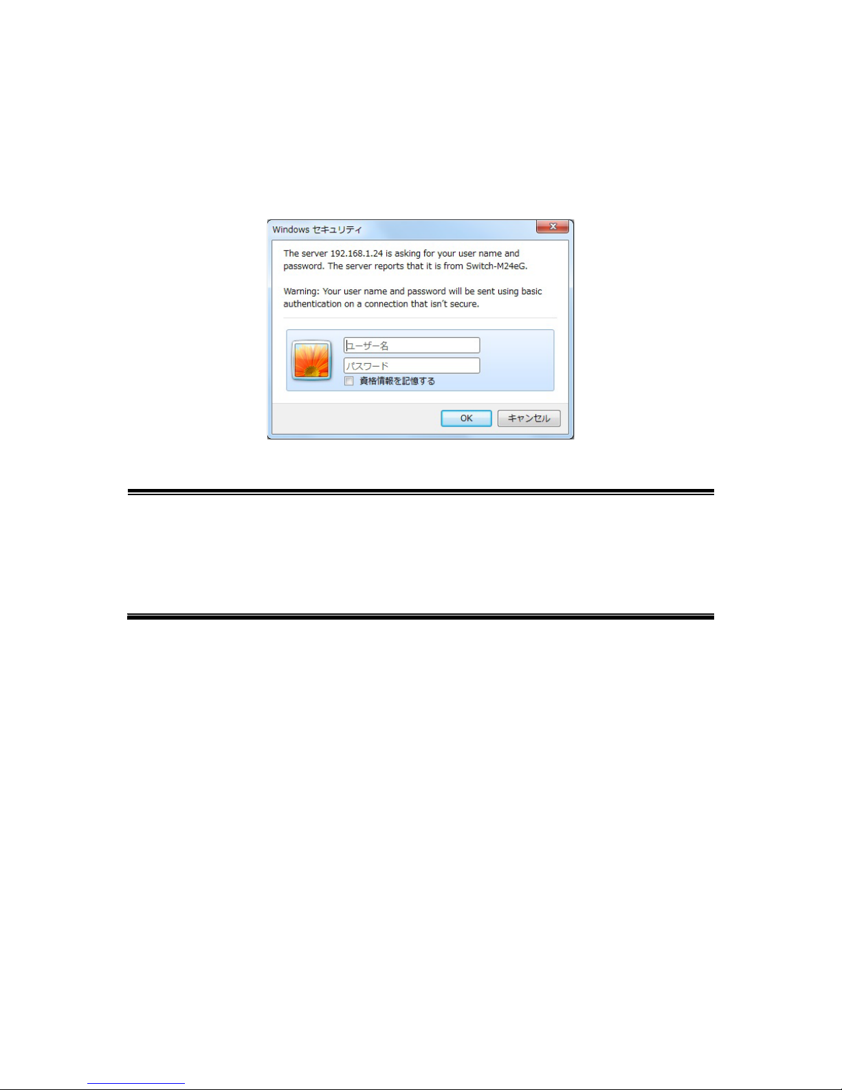
2.2. Access to Web Control Function
To use the Web control function, enter the IP address of this switch in the address
bar of your Web browser and press the Enter key. Then, a login screen, similar to
Figure 2-1, is displayed. Enter your user name and password.
The factory default user name is "manager" and password is "manager."
Figure 2-1 Login Screen
Note: If the login screen is not displayed, check the following:
(1) Are the IP address, subnet mask and default gateway of this switch
properly configured?
(2) Is the IP address of this switch entered on the Web browser?
(3) Is the Web control function enabled?
(4) Is the IP address of the terminal to be accessed equal to the network
address of this switch?
When the above information has been authenticated properly, the screen shown
in Figure 2-2 will appear for selecting a display language.
Select the type of the language in which you want to show menus, and press "OK."

13
Figure 2-2 Select Screen for Display Language
Select a language, and the screen shown in Figure 2-3 will appear.
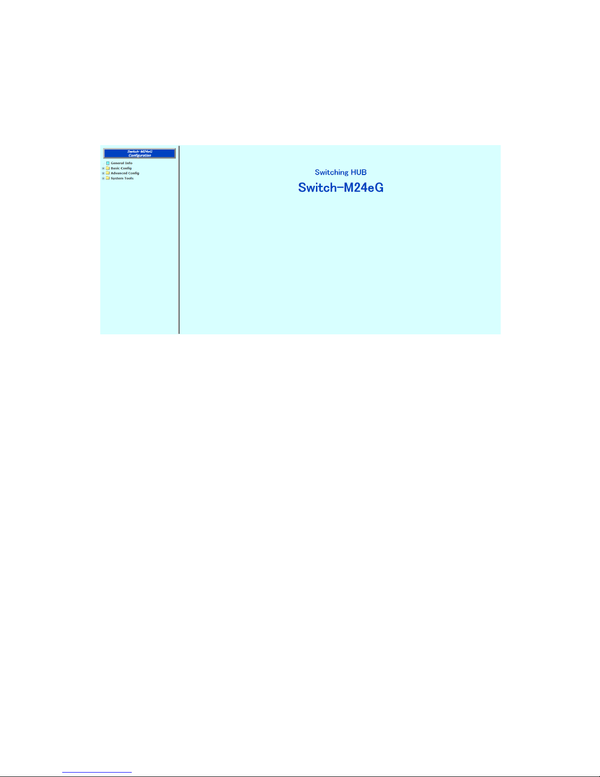
14
Figure 2-3 Main Screen

15
The left side of the main screen shows a list of actions available to you on this
screen.
(1) General Info
Displays a list of basic information of this switch.
(2) Basic Config
Configure the basic settings such as IP address and port settings.
(3) Advanced Config
Configure the advanced settings such as VLAN, QoS, and IGMP snooping.
(4) System Tools
Use these management tools to update the firmware and browse system logs.
To conduct operation management, it is recommended to conduct the "Basic Config" first, before configuring other advanced settings.
16
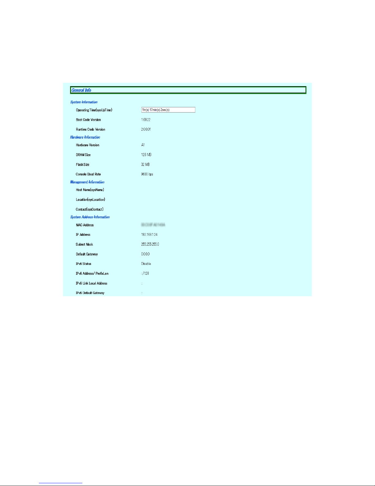
2.3. Displaying Basic Information
Selecting "General Info" opens the screen shown in Figure 2-4. This screen shows a
list of basic information of this switch.
Figure 2-4 General Info

17
Screen Description
System Information
Displays the operating time and firmware version of this switch.
Operating Time Displays the cumulative time since the power on of this
switch.
Boot Code
Version
Displays this switch's firmware version.
* The firmware update described in Section 3.3.1 is available
only for runtime codes.
Runtime Code
Version
Hardware Displays the hardware information.
Hardware Version Displays the hardware version.
DRAM Size Displays the size of the installed DRAM.
Flash Size Displays the size of the installed Flash memory.
Console Baud Rate Displays the baud rate of the console.
System Fan Status Displays the operation status of the installed fan.
Displays "Good" when the fan is operating normally
and "Fail" when it fails or stops.
System Temperature Displays the internal temperate of the switch.
The temperature sensors measure the temperatures
of the CPU and system.
Management Configure the items shown here in accordance with "Administration Configra-
tion" in Section 3.1.1.
Host Name Displays the switch name. The factory default setting is
blank. For configuration details, refer to Section 3.1.1.
Location Displays the switch's location. The factory default setting is
blank. For configuration details, refer to Section 3.1.1.
Contact Displays the contact information. The factory default setting
is blank. For configuration details, refer to Section 3.1.1.
System Address Configure the items shown here in accordance with "IP Config" in Section
3.1.2.
MAC Address Displays the MAC address of this switch. This value is
uniquely assigned to each device and cannot be changed.
IP Address Displays the switch's current IP address. "0.0.0.0" is the fac-
tory default setting. For configuration details, refer to Section 3.1.2.
Subnet Mask Displays the switch's current subnet mask. "0.0.0.0" is the
factory default setting. For configuration details, refer to
Section 3.1.2.
Default
Gateway
Displays the IP address of the router for the default gateway. "0.0.0.0" is the factory default setting. For configura-
tion details, refer to Section 3.1.2.
★ IPv6 アクセス Displays whether the IPv6 address is enabled or disabled.
★IPv6アドレス/
プレフィックス長
Displays the current IPv6 address and prefix length of this
switch. "::/128" is the factory default setting. For configura-
tion details, refer to Section 3.1.2.
★ IPv6 リンク
★ローカルアドレ
ス
Displays the current IPv6 link local address of this switch. "::"
is the factory default setting. For configuration details, refer
to Section 3.1.2.
★IPv6デフォルト
ゲートウェイ
Displays the IPv6 address of the router for the default gate-
way. "::" is the factory default setting. For configuration
details, refer to Section 3.1.2.
18
3. Switch Configuration
After completing configuration, you must save the configuration information in
accordance with Section 3.3.3. Unless the configuration information is saved, the
settings configured so far will not be reflected after restart.
3.1. Basic Config
3.1.1. Administration Configration
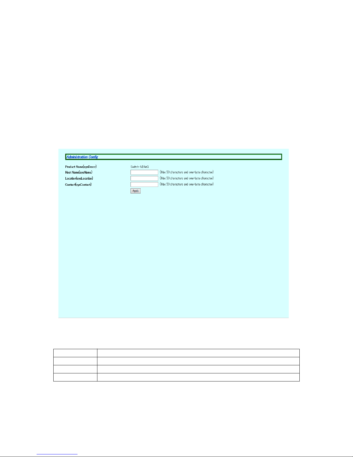
Select "Basic Config" and "Administration Config" to open the screen shown in Figure 3-1. Select this screen to display this switch's information. On this screen, you
can configure the administrative information, such as device name.
Figure 3-1 Administration Configration
Screen Description
Products Name Displays the system information. This item is not editable.
Host Name Displays the system name. The factory default setting is blank.
Location Displays the device installation location. The factory default setting is blank.
Contact Displays the contact information. The factory default setting is blank.
19
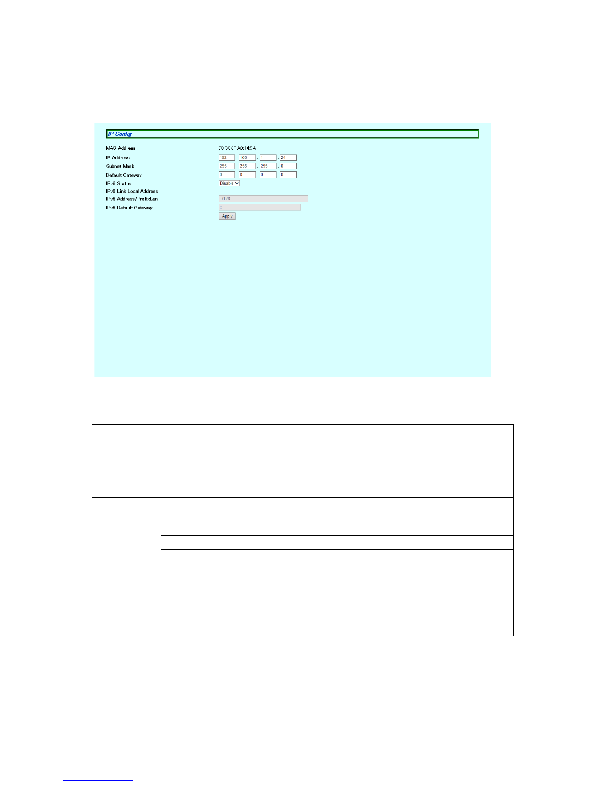
3.1.2. IP Config
Select "Basic Config" and "IP Config" to open the screen shown in Figure 3-2. On
this screen, you can configure the IP address of this switch.
Figure 3-2 IP Config
Screen Description
MAC Address Displays the MAC address of this switch.
This item is uniquely assigned to each device and cannot be changed.
IP Address Displays the current IP address.
"0.0.0.0" is the factory default setting.
Subnet
Mask
Displays the current subnet mask.
"0.0.0.0" is the factory default setting.
Default
Gateway
Displays the IP address of the router, set as a current default gateway.
"0.0.0.0" is the factory default setting.
IPv6 Status Displays whether access via IPv6 is enabled or disabled.
Enable Enables access via IPv6.
Disable Disables access via IPv6. (Factory default setting)
IPv6 Link Local
Address
Displays the current IPv6 link local address. "::" is the factory default setting.
IPv6 Address
/Prefix Length
Displays the current IPv6 address and prefix length. "::/128" is the factory default
setting.
IPv6 Default
Gateway
Displays the IPv6 address of the router, set as a current default gateway. "::" is the
factory default setting.

20
Note: Unless you configure these settings, you cannot use the SNMP management
functions and remotely connect to the switch via Telnet or SSH. Be sure to
configure them. If you are unsure, consult the network administrator. All IP
addresses on the local network must be unique, and no duplications are
allowed. In addition, you need to set the subnet mask and the default gateway, which are the same for other devices on the same subnet using this
switch.
21
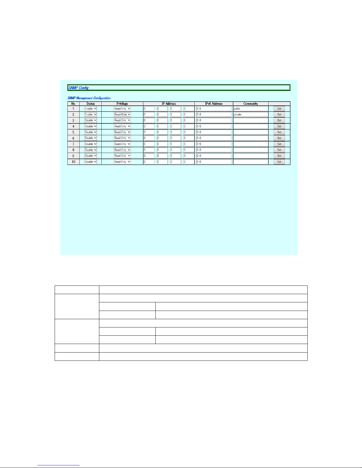
3.1.3. SNMP Config
Select "Basic Config" and "SNMP" and then "SNMPConfig" to open the screen
shown in Figure 3-3. On this screen, you can configure the SNMP manager settings.
Figure 3-3 snMP Config
Screen Description
No. Displays the entry number on the SNMP manager List.
Status Displays the SNMP manager status.
Enable The SNMP manager is enabled.
Disable The SNMP manager is disabled.
Privilege Displays the access privilege of the SNMP manager.
Read-Write Both the read and write operations are allowed.
Read-Only Only the read operation is allowed.
IP Address This is the IP address for an SNMP manager.
Community This is the community name used for SNMP access.
22
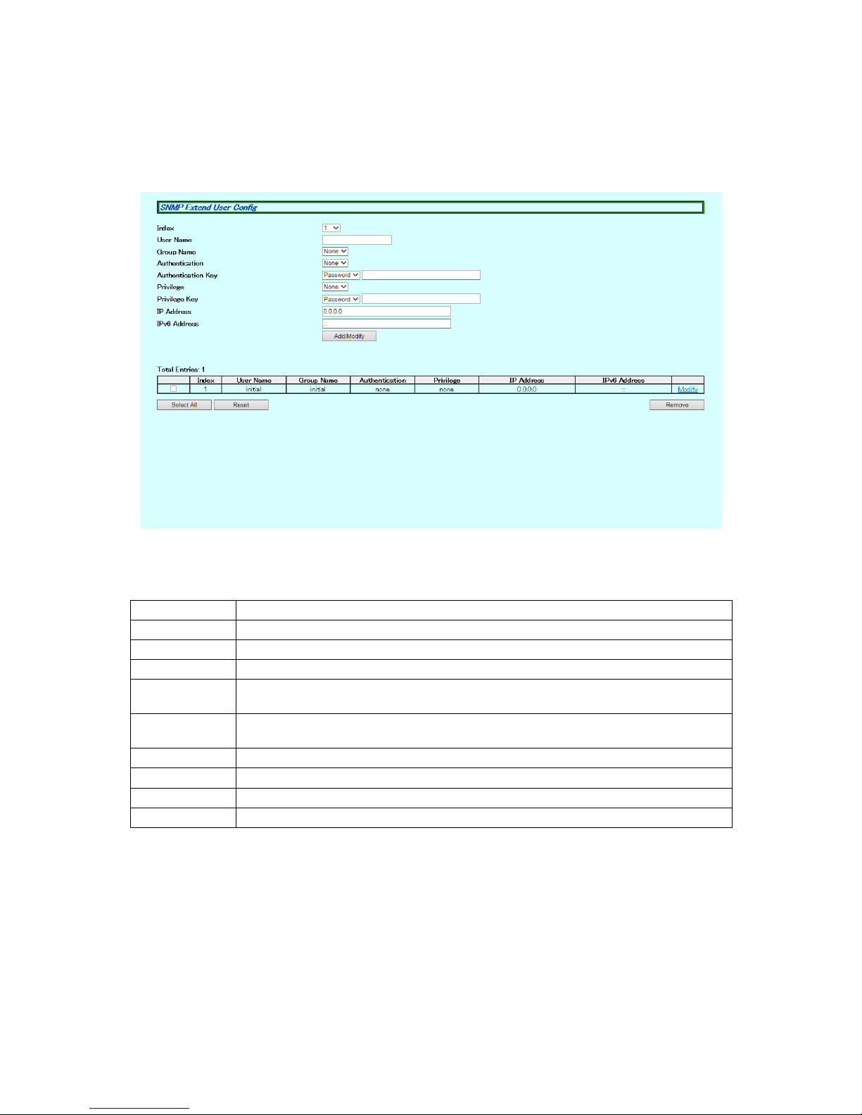
3.1.4. SNMP Extend User Config
Select "Basic Config," "SNMP," and then "SNMP Extend User Config" to open the
screen shown in Figure 3-4. On this screen, you can configure the SNMP manager
settings.
Figure 3-4 SNMP Extend User Config
Screen Description
Total Entry Displays the number of created SNMP users (number of indexes) .
Index This is the entry number of the SNMP user.
User Name Displays the name of the SNMP user.
Group Name Displays the name of the SNMP group.
Authentication Displays the authentication method. The following options are used: "none,"
"MD5," and "SHA."
Authentication
Key
Sets an authentication key. Specify "Password" or "Key," and enter a password or
key.
Privilege Displays the encryption system. The options "none" and "DES" are used.
Privilege Key Sets a privilege key. Specify "Password" or "Key," and enter a password or key.
IP Address Displays the IPv4 address accessible via SNMP.
IPv6 Address Displays the IPv6 address accessible via SNMP.
23
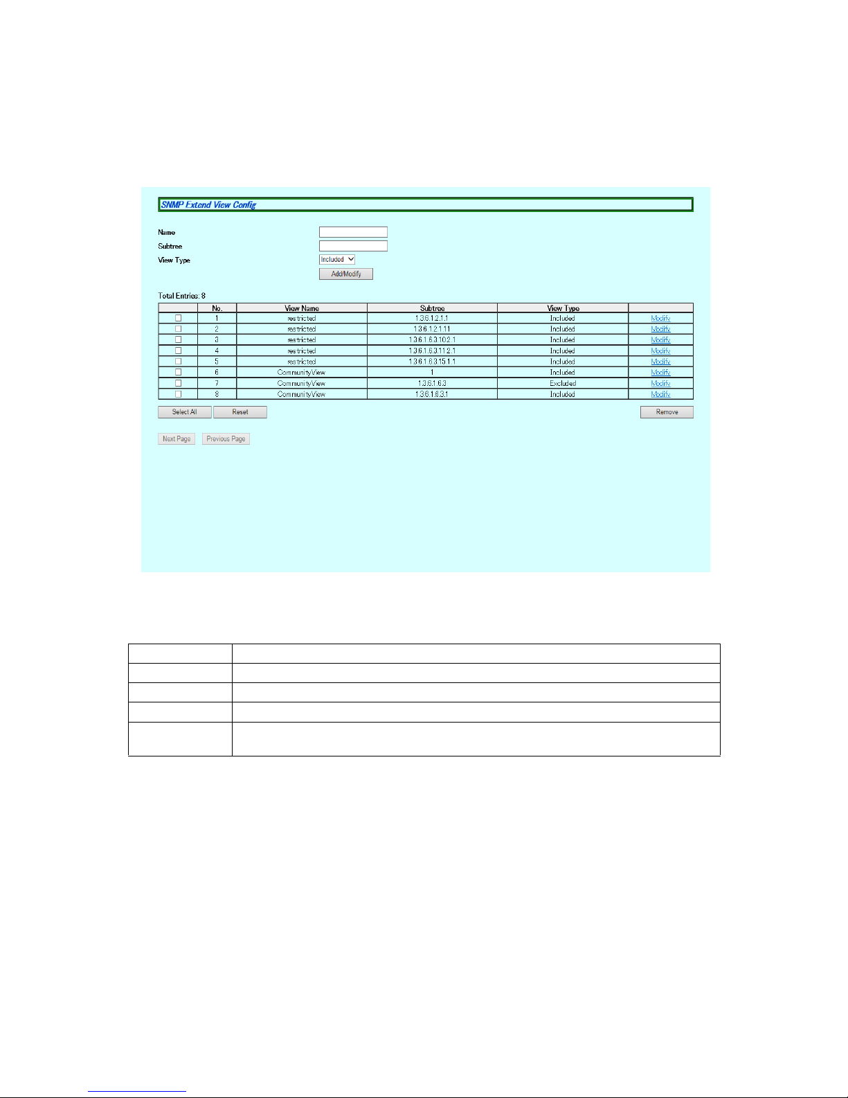
3.1.5. SNMP Extend View Config
Select "Basic Config," "SNMP," and then "SNMP Extend View Config" to open the
screen shown in Figure 3-5. On this screen, you can configure the SNMP manager
settings.
Figure 3-5 SNMP Extend View Config
Screen Description
Total Entry Displays the number of created SNMP view entries.
No This is the entry number of the SNMP view.
View Name Displays the name of the SNMP view.
Subtree Displays the subtree of the SNMP view.
View Type Displays the type of the SNMP view. The options "Included" and "Excluded" are
used.
24
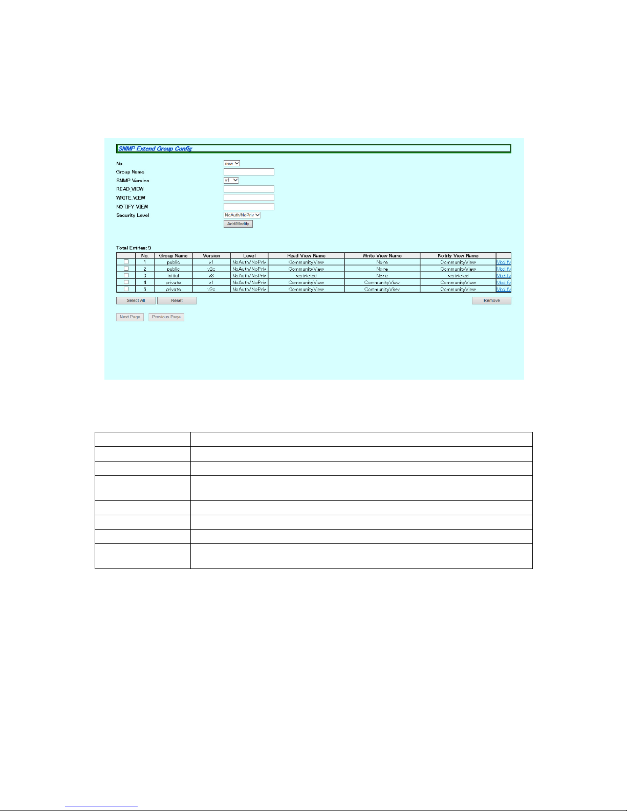
3.1.6. SNMP Extend Group Config
Select "Basic Config," "SNMP," and then "SNMP Extend Group Config" to open the
screen shown in Figure 3-6. On this screen, you can configure the SNMP manager
settings.
Figure 3-6 SNMP Extend Group Config
Screen Description
Total Entry Displays the number of created SNMP group entries.
No This is the entry number of the SNMP group.
Group Name Displays the name of the SNMP group.
SNMP Version Displays the version of the SNMP group. The following options are used: "v1,"
"v2c," and "v3."
READ_VIEW Displays the name of the view to be read.
WRITE_VIEW Displays the name of the view to be written.
NOTIFY_VIEW Displays the name of the view to be notified.
Security Level Displays the security level of the SNMP group. The following options are used:
"NoAuth/NoPriv," "Auth/No Priv," and "Auth/Priv."

25
3.1.7. Basic Trap Configuration
Select "Basic Config" and "SNMP" and then "Basic Trap Configuration" to open the
screen shown in Figure 3-7. On this screen, you can configure the SNMP Trap settings.
Figure 3-7 Basic Trap Configuration
Screen Description
No. Displays the entry number for the trap receiver.
Status Displays the trap sending setting.
Enable Sends traps.
Disable Does not send traps. (Factory default setting)
Type Displays the type of traps.
v1 Sends traps of SNMP v1. (Factory default setting)
v2c Sends traps of SNMP v2c.
v2 Sends traps of SNMP v3.
IP Address This is the IP address for the trap receiver.
IPv6 Address This is the IPv6 address for the trap receiver.
Community This is the community name used for trap sending.
26
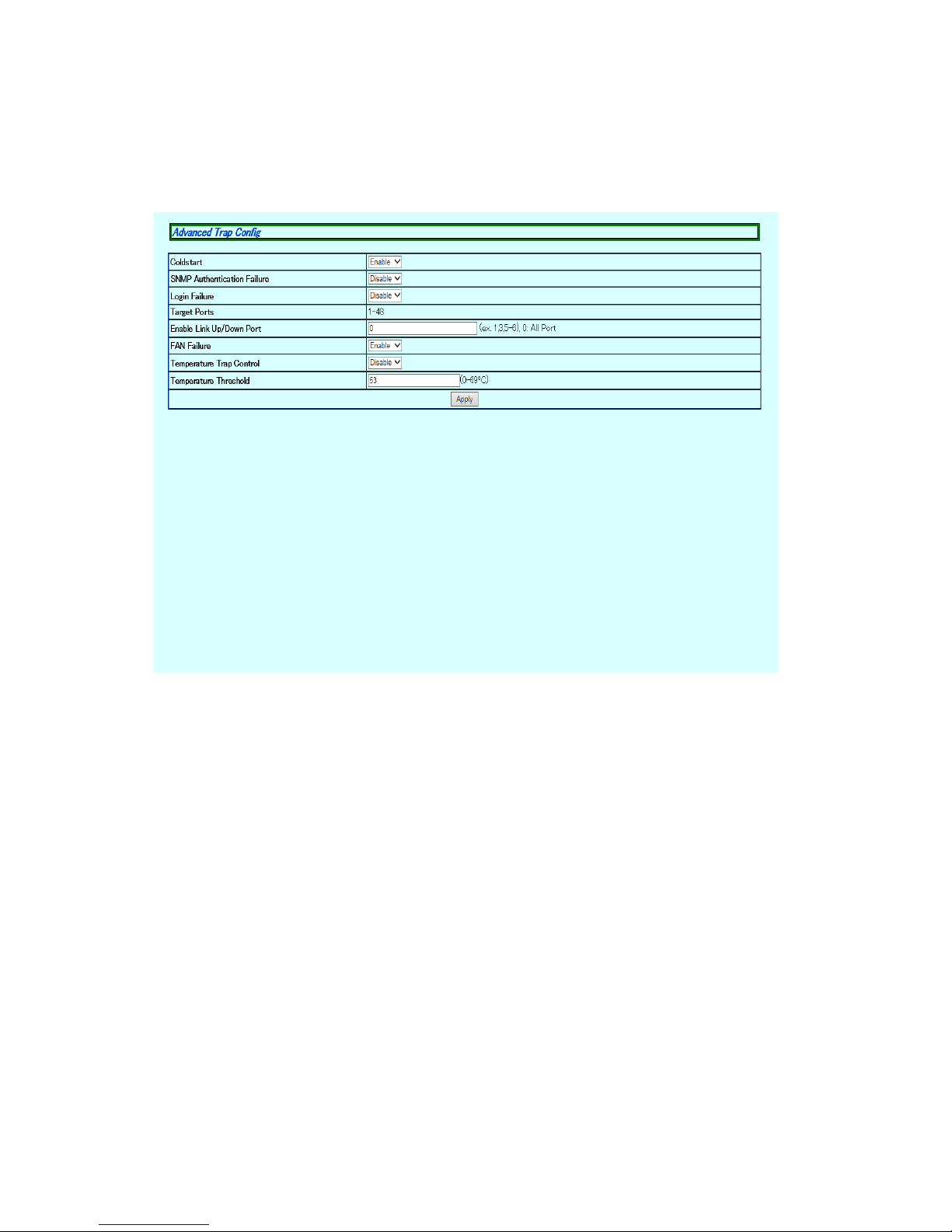
3.1.8. Advanced Trap Configuration
Select "Basic Config" and "SNMP" and then "Advanced Trap Configuration" to open
the screen shown in Figure 3-8. On this screen, you can configure the operations
for sending traps.
Figure 3-8 Advanced Trap Configuration

27
Screen Description
SNMPAuthentication Failuer
Displays the trap sending settings for an SNMP authentication failure.
Enable Enables the trap sending.
Disable Disables the trap sending. (Factory default setting)
Target Ports Displays and configures a port to which the trap is sent when its link status
changes.
Target Port Number Displays a target port that has been configured.
Enable Link UP/ Configures a port to which the trap is sent.
Temperature Trap Displays whether the trap sending is enabled or disabled at an abnormal sys-
tem temperature.
Enable Enables the trap sending.
Disable Disables the trap sending. (Factory default setting)
Temperature Displays the threshold temperature value to send the trap.
Fan Failure Displays whether the trap sending is enabled or disabled for an abnormal sys-
tem fan.
Enable Enables the trap sending. (Factory default setting)
Disable Disables the trap sending.

28
3.1.9. Basic Port Config
Select "Basic Config" and "Port Config" and then "Basic Port Configuration" to open
the screen shown in Figure 3-9. On this screen, you can configure port status display settings and mode and other settings.
Figure 3-9 Basic Port Config

29
Screen Description
Target Port Selecting
Select multiple target ports for configuring settings at a time.
Click the "Select All" button, and all ports will be selected.
Click the "Reset" button, and all ports will be deselected.
Click the "Set selected port (s) " button after selecting and changing the items
for configuring settings at a time, and the same settings will apply to the
selected ports.
Port Number Displays the port number.
Trunk Displays the group number for a trunked port.
Type Displays the port type.
1000T The port type is 1000BASE-T.
1000X The port type is SFP port.
Port Status Displays the current port status. For all ports, "Enable" is the factory default set-
ting.
Enable The port is available.
Disable The port is not available.
Link Status Displays the current link status.
Up A link has been established successfully.
Down A link has not been established.
Duplex Mode Displays the communication speed and full-duplex/half-duplex settings.
For all ports, "Auto" is the factory default setting.
Auto Auto negotiation mode
100M/Full 100 Mbps full-duplex
100M/Half 100 Mbps half-duplex
10M/Full 10 Mbps full-duplex
10M/Half 10 Mbps half-duplex
Flow Control Displays the flow control settings.
For all ports, "Disable" is the factory default setting.
Enable The flow control is enabled.
Disable The flow control is disabled.
Auto-MDI Displays the Auto MDI/MDI-X function settings. The factory default setting is
"Disable" for a downlink port and "Enable" for an uplink twisted pair port.
Enable The Auto-MDI/MDI-X function is enabled.
Disable The Auto-MDI/MDI-X function is disabled.
 Loading...