

Panasonic PAN9420 User Manual
Wireless Modules
PAN9420
Fully Embedded Stand-Alone Wi-Fi Module
Product Specification
Rev. 1.1
PAN9420 Wi-Fi Module
Overview
The PAN9420 is a 2.4 GHz ISM band
Wi-Fi-embedded module which includes a wireless
radio and an MCU for easy integration of
Wi-Fi connectivity into various electronic devices.
Features
•
Fully embedded: integrated full-featured network
stack
•
Contains all necessary IoT functionality (Place &
Play)
•
Integrated webserver with AJAX/JSON for web
applications
•
No stack or software implementation needed on
a host MCU
•
Simultaneous support of Access-Point- &
Infrastructure mode
•
Fully automatical IP configuration
•
DHCP server offers IP configuration in AP mode
•
Access by names (http://yourdevice)
•
Integrated TCP/IP network stack: IPv4, ARP,
and AutoIP
•
Supports TLS/SSL, https, and Wi-Fi security
(WPA2) for secure data connection
•
Over-the-Air firmware update
•
Two UART interfaces (command and
transparent data)
•
Integrated QSPI flash memory for customer web
contents and configuration file
•
Programming via standard JTAG
•
Evaluation kit with pre-installed web application for
quick prototyping available
•
Evaluation and development tool WiFigurator for
Windows
•
Getting started tutorials, PC tool, quickstart guide
•
Wide temperature range of -40 °C to +85 °C
Characteristics
•
Surface Mount Type (SMT)
29.0 mm x 13.5 mm x 2.66 mm
•
Marvell® 88MW300 MCU/WLAN System-on-Chip
(SoC) inside
•
Tx power up to +16 dBm @ IEEE 802.11b
•
Rx sensitivity of -97 dBm @ IEEE 802.11b DSSS
1 Mbps
•
20 MHz channels up to 72 Mbps
•
Power supply 3.0 to 3.6 V
•
Current consumption 150 mA (mix mode
Tx/Rx @ 11b, 11 Mbps), 75 mA Rx, 310 mA Tx
peak
•
Power down mode < 1 mA power consumption
•
Low power mode available
Delta PAN9420 vs PAN9320
•
PAN9320 replaceable by PAN9420 without
changes on mother PCB
•
Reduced power consumption in transmit, idle, and
power down
•
Enhanced temperature range of -40 °C to +85 °C
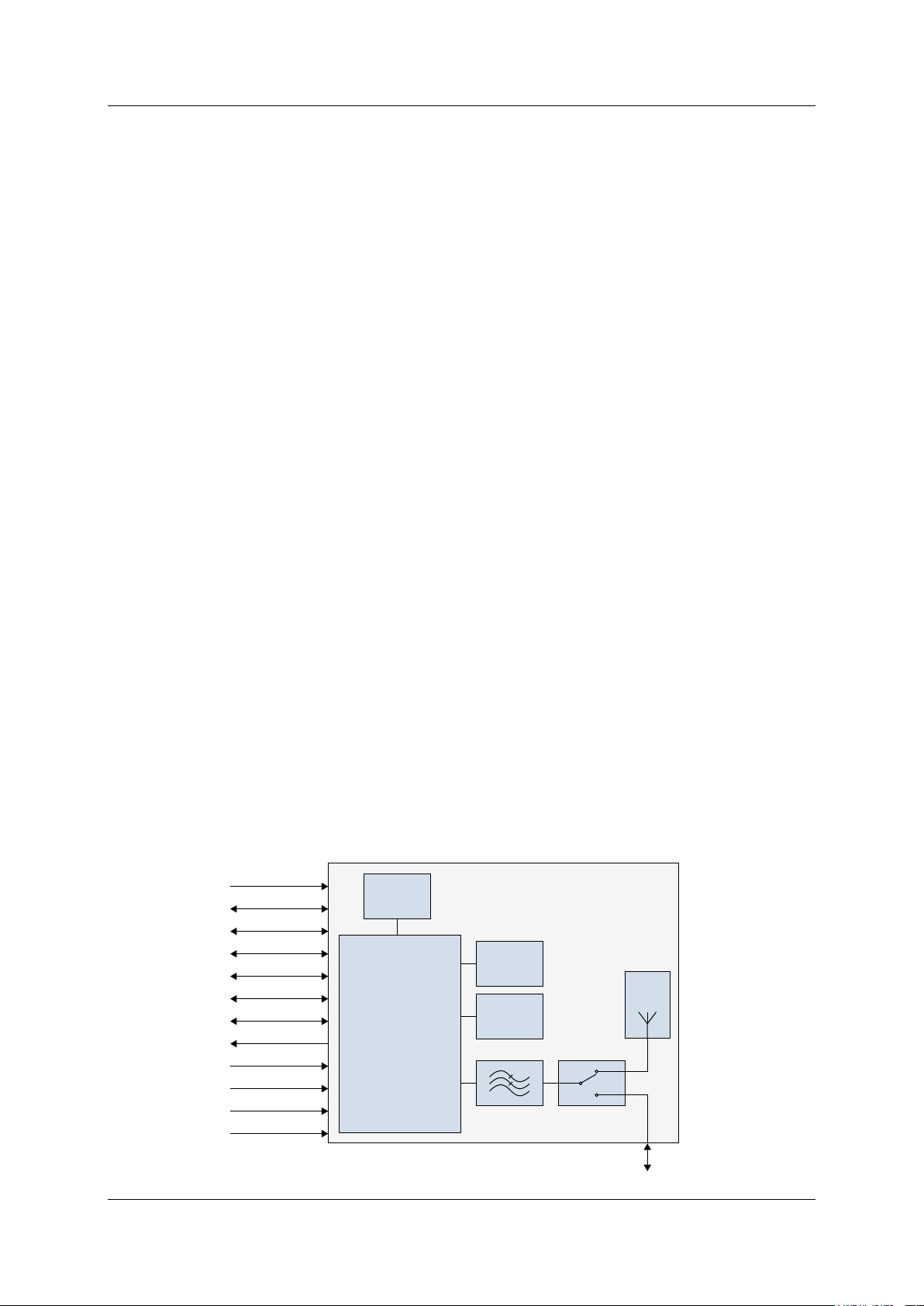
Chip
Antenna
SPDT
88MW300
MCU/Radio SoC
Crystal
32.768 kHz
QSPI Flash
32 Mbit
SPI
UART0
UART1
GPIOs
Status LEDs
MCU Ready
Resetn
Factory Reset
V SPDT
Wake Ups
JTAG
Vcc 3.3 V
LPF
RF-Pad
PAN9420
Fully Embedded Wi-Fi Module
IEEE 802.11 b/g/n
Crystal
38.4 MHz
Block Diagram
Product Specification Rev. 1.1 Page 2

PAN9420 Wi-Fi Module
By purchase of any of the products described in this document the customer accepts the
document's validity and declares their agreement and understanding of its contents and
recommendations. Panasonic reserves the right to make changes as required at any time
without notification. Please consult the most recently issued Product Specification before
initiating or completing a design.
© Panasonic Industrial Devices Europe GmbH 2017.
All rights reserved.
This Product Specification does not lodge the claim to be complete and free of mistakes.
Engineering Samples (ES)
If Engineering Samples are delivered to the customer, these samples have the status
“Engineering Samples”. This means that the design of this product is not yet concluded.
Engineering Samples may be partially or fully functional, and they may differ from the published
Product Specification.
Engineering Samples are not qualified and they are not to be used for reliability testing or series
production.
Disclaimer
The customer acknowledges that samples may deviate from the Product Specification and may
bear defects due to their status of development and the lack of qualification mentioned above.
Panasonic rejects any liability or product warranty for Engineering Samples. In particular,
Panasonic disclaims liability for damages caused by:
The use of the Engineering Sample other than for evaluation purposes, particularly the
installation or integration in another product to be sold by the customer,
Deviation or lapse in function of the Engineering Sample,
Improper use of the Engineering Sample.
Panasonic Industrial Devices Europe GmbH disclaims any liability for consequential and
incidental damages. In case of any queries regarding the Engineering Samples, please contact
your local sales partner or the related product manager.
Product Specification Rev. 1.1 Page 3

PAN9420 Wi-Fi Module
Table of Contents
1 About This Document ......................................................................................................................... 5
1.1 Purpose and Audience .............................................................................................................. 5
1.2 Revision History ......................................................................................................................... 5
1.3 Use of Symbols ......................................................................................................................... 5
1.4 Related Documents ................................................................................................................... 5
2 Overview .............................................................................................................................................. 6
2.1 Block Diagram ........................................................................................................................... 7
2.2 Pin Configuration ....................................................................................................................... 8
2.3 Host Interfaces ........................................................................................................................ 11
2.4 Peripheral Bus Interface .......................................................................................................... 11
2.5 WLAN Features ....................................................................................................................... 12
3 Detailed Description ......................................................................................................................... 14
3.1 Dimensions .............................................................................................................................. 14
3.2 Footprint .................................................................................................................................. 15
3.3 Packaging ................................................................................................................................ 16
3.4 Case Marking .......................................................................................................................... 19
4 Specification ..................................................................................................................................... 20
4.1 Default Test Conditions ................................................................................................ ........... 20
4.2 Absolute Maximum Ratings ..................................................................................................... 20
4.3 Recommended Operating Conditions ...................................................................................... 21
4.4 RF Electrical Characteristics .................................................................................................... 29
4.5 Reliability Tests ....................................................................................................................... 33
4.6 Recommended Soldering Profile ............................................................................................. 34
5 Cautions, Life Support Policy, RoHS Declaration, and Regulatory Information ......................... 35
5.1 Cautions .................................................................................................................................. 35
5.2 Life Support Policy ................................................................................................................... 38
5.3 RoHS and REACH Declaration ............................................................................................... 38
5.4 Regulatory Information ............................................................................................................ 38
6 Appendix ........................................................................................................................................... 44
6.1 Ordering Information ................................................................................................................ 44
6.2 Contact Details ........................................................................................................................ 45
Product Specification Rev. 1.1 Page 4
PAN9420 Wi-Fi Module
Revision
Date
Modifications/Remarks
0.1
01.02.2017
1st preliminary version
0.2
31.05.2017
Improved layout
1.0
02.06.2017
Technical data corrected
1.1
19.06.2017
FCC/IC/RED information added
Symbol
Description
Note
Indicates important information for the proper use of the product.
Non-observance can lead to errors.
Attention
Indicates important notes that, if not observed, can put the product’s functionality
at risk.
[chapter number]
[chapter title]
Cross reference
Indicates cross references within the document.
Example:
Description of the symbols used in this document 1.3 Use of Symbols.
1 About This Document
1 About This Document
1.1 Purpose and Audience
This Product Specification provides details on the functional, operational, and electrical
characteristics of the Panasonic PAN9420 module. It is intended for hardware design,
application, and OEM engineers. The product is referred to as “the PAN9420” or “the module”
within this document.
1.2 Revision History
1.3 Use of Symbols
1.4 Related Documents
Please refer to the Panasonic website for related documents 6.2.2 Product Information.
Product Specification Rev. 1.1 Page 5

PAN9420 Wi-Fi Module
The PAN9420 supports Over-the-Air firmware updates. In order to make use
of this feature, the customer needs to ensure that the appropriate
preconditions are fulfilled and that a suitable environment is provided,
particularly with regard to:
•
Module configuration
•
Utilization of the related module interface commands
•
Server infrastructure and application
2 Overview
2 Overview
The PAN9420 is a 2.4 GHz 802.11 b/g/n embedded Wi-Fi module with integrated stack and API
that minimizes firmware development and includes a full security suite. The module is
specifically designed for highly integrated and cost-effective applications. The module includes
a fully shielded case, integrated crystal oscillators, and a chip antenna.
The module combines a high-performance CPU, high-sensitivity wireless radio, baseband
processor, medium access controller, encryption unit, boot ROM with patching capability,
internal SRAM, and in-system programmable flash memory. The module’s integrated memory is
available to the application for storing web content such as HTML pages or image data.
Parallel support of access point and infrastructure mode allows easy setup of simultaneous
Wi-Fi connections from the module to smart devices and home network routers.
The pre-programmed Wi-Fi SoC firmware enables client (STA), micro access point (uAP), and
Ad-hoc mode (Wi-Fi Direct) applications. With the transparent mode, raw data can be sent from
the UART to the air interface to smart devices, web servers, or PC applications.
Please refer to the Panasonic website for related documents 6.2.2 Product Information.
Further information on the variants and versions 6.1 Ordering Information.
Product Specification Rev. 1.1 Page 6
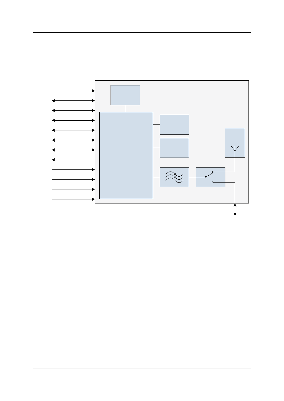
PAN9420 Wi-Fi Module
Chip
Antenna
SPDT
88MW300
MCU/Radio SoC
Crystal
32.768 kHz
QSPI Flash
32 Mbit
SPI
UART0
UART1
GPIOs
Status LEDs
MCU Ready
Resetn
Factory Reset
V SPDT
Wake Ups
JTAG
Vcc 3.3 V
LPF
RF-Pad
PAN9420
Fully Embedded Wi-Fi Module
IEEE 802.11 b/g/n
Crystal
38.4 MHz
2 Overview
2.1 Block Diagram
Product Specification Rev. 1.1 Page 7
PAN9420 Wi-Fi Module
No
Pin Name
Pin Type
Description
1
GND
Ground Pin
Connect to ground
2
GPIO41
Digital I/O
Digital I/O #4
3
GPIO51
Digital I/O
Digital I/O #5
4
NC
NC
Do not connect
5
NC
NC
Do not connect
6
NC
NC
Do not connect
7
3.3 V
Power
3.0 V-3.6 V power supply connection (typical 3.3 V)
8
3.3 V
Power
3.0 V-3.6 V power supply connection (typical 3.3 V)
9
UART1 CTS
Digital In
CTSn for UART1 (using hardware flow control)
10
UART1 RTS
Digital Out
RTSn for UART1 (using hardware flow control)
11
UART1 TXD
Digital Out
TXD for UART1
12
UART1 RXD
Digital In
RXD for UART1
13
NC
NC
Do not connect
14
GND
Ground Pin
Connect to ground
15
GND
Ground Pin
Connect to ground
1
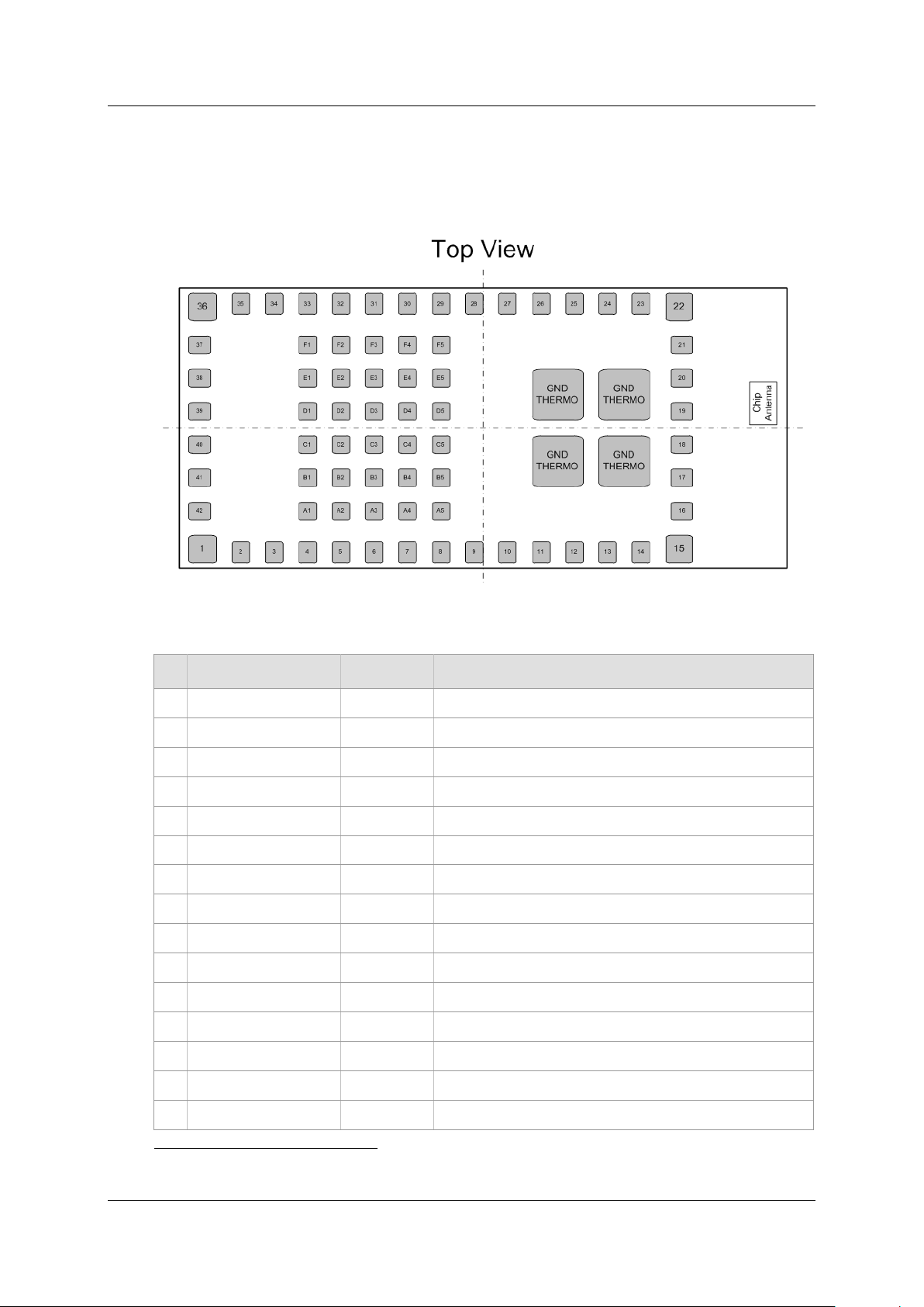
2 Overview
2.2 Pin Configuration
Pin Assignment
Pin Functions
All GPIOs are initially set to output with low level
Product Specification Rev. 1.1 Page 8

PAN9420 Wi-Fi Module
No
Pin Name
Pin Type
Description
16
NC/RF
NC/Analog IO
RF in/out over 50Ω bottom pad
17
GND
Ground Pin
Connect to ground
18
GND
Ground Pin
Connect to ground
19
GND
Ground Pin
Connect to ground
20
GND
Ground Pin
Connect to ground
21
GND
Ground Pin
Connect to ground
22
GND
Ground Pin
Connect to ground
23
GND
Ground Pin
Connect to ground
24
GND
Ground Pin
Connect to ground
25
GND
Ground Pin
Connect to ground
26
W STAT LED
Digital Out
Connect to LED wireless (Wi-Fi) status, active low
27
UART0 TXD/DUAL STAT
Digital Out
TXD for UART0/UART1 state (binary data or command)
28
UART0 RXD/DUAL SW
Digital In
RXD for UART0/UART1 toggle switch for the control of the state
29
GPIO491
Digital I/O
Digital I/O #49
30
GPIO481
Digital I/O
Digital I/O #48
31
GPIO471
Digital I/O
Digital I/O #47
32
GPIO461
Digital I/O
Digital I/O #46
33
STAT LED1
Digital Out
Connect to LED MCU status (heartbeat), active low
34
STAT LED2
Digital Out
Connect to LED IP connectivity (allocated IP), active low
35
STAT LED3
Digital Out
Connect to LED Error (active during booting), active low
36
GND
Ground Pin
Connect to ground
37
RESETn
Digital In
Reset MCU, active low
38
WAKE UP02
Digital In
Wake up signal for MCU/WLAN SoC, active high
39
NC
NC
Do not connect
40
NC
NC
Do not connect
41
MCU READY
Digital Out
Connect to LED MCU ready (booting ready), active high
42
FACTORY RESET
Digital In
Factory reset (valid after 10 seconds), active high
A1
NC
NC
Do not connect
A2
NC
NC
Do not connect
A3
NC
NC
Do not connect
A4
SPDT V1
Input Signal
Do not connect if on-board antenna In/Out is desired, for RF-Pad
In/Out 4.3.2 Module Selectable RF-In/Output.
2
2 Overview
Connect to HOST MCU (wake up after shut-off mode, active high), use 10 kOhm resistor to GND at pin
Product Specification Rev. 1.1 Page 9

PAN9420 Wi-Fi Module
No
Pin Name
Pin Type
Description
A5
SPDT V2
Input Signal
Do not connect if on-board antenna In/Out is desired, for RF-Pad
In/Out 4.3.2 Module Selectable RF-In/Output.
B1
NC
NC
Do not connect
B2
NC
NC
Do not connect
B3
NC
NC
Do not connect
B4
NC
NC
Do not connect
B5
NC
NC
Do not connect
C1
NC
NC
Do not connect
C2
NC
NC
Do not connect
C3
WAKE UP12
Digital In
Wake up signal for MCU/WLAN SoC, active high
C4
NC
NC
Do not connect
C5
NC
NC
Do not connect
D1
TDI
Digital In
TDI for JTAG (option for flashing in production process)
D2
TRSTn
Digital In
TRSTn for JTAG (option for flashing in production process)
D3
NC
NC
Do not connect
D4
NC
NC
Do not connect
D5
NC
NC
Do not connect
E1
TDO
Digital Out
TDO for JTAG (option for flashing in production process)
E2
TCK
Digital Out
TCK for JTAG (option for flashing in production process)
E3
TMS
Digital I/O
TMS for JTAG (option for flashing in production process)
E4
NC
NC
Do not connect
E5
NC
NC
Do not connect
F1
NC
NC
Do not connect
F2
NC
NC
Do not connect
F3
GND
Ground Pin
Connect to ground
F4
GND
Ground Pin
Connect to ground
F5
GND
Ground Pin
Connect to ground
GND THERMO
Thermal Pin
Connect to ground
GND THERMO
Thermal Pin
Connect to ground
GND THERMO
Thermal Pin
Connect to ground
GND THERMO
Thermal Pin
Connect to ground
2 Overview
Product Specification Rev. 1.1 Page 10

PAN9420 Wi-Fi Module
UART0 Interface
•
2-wire data transfer (RX, TX)
•
Programmable baud rate
(300 bps to 1.5 Mbps)
•
Data format (LSB first)
•
Data bit: (5-8 bit)
•
Parity bit: (0-3 bit)
•
Stop bit: (1-2 bit)
UART1 Interface
•
4-wire data transfer
(RX, TX, RTS, CTS)
•
Programmable baud rate
(300 bps to 1.5 Mbps)
•
Data format (LSB first)
•
Data bit: (5-8 bit)
•
Parity bit: (0-3 bit)
•
Stop bit: (1-2 bit)
Features
Characteristics
JTAG
•
Standard JTAG interface
General Purpose I/O
(GPIO) Interface
•
Defined GPIOs, I/O configured to either input or output (on/off)
•
GPIOs with LED status functionality (ready, heartbeat, IP-connectivity,
error and WLAN connectivity)
Wake Up 0 / 1
•
External signal for wake-up after shut-off mode
2 Overview
2.3 Host Interfaces
Further information 4.3.7 Host Interface Specification.
2.4 Peripheral Bus Interface
Embedded MCU and WLAN Radio (SoC)
Further information 4.3.8 Peripheral Interface Specification.
Product Specification Rev. 1.1 Page 11

PAN9420 Wi-Fi Module
Type
Features
IEEE 802.11/Standards
•
802.11 data rates 1 and 2 Mbps (DSSS)
•
802.11b data rates 5.5 and 11 Mbps (CCK)
•
802.11g data rates 6, 9, 12, 18, 24, 36, 48, and 54 Mbps (OFDM)
•
802.11b/g performance enhancements
•
802.11n-compliant with maximum data rates up to 72 Mbps
(20 MHz channel)
•
802.11d international roaming3
•
802.11i enhanced security
•
802.11k radio resource measurement3
•
802.11r fast hand-off for AP roaming3
•
802.11w protected management frames3
•
Support clients (stations) implementing IEEE Power Save mode
•
Wi-Fi direct connectivity3
WLAN MAC
•
Simultaneous peer-to-peer and Infrastructure Modes
•
RTS/CTS for operation and DCF
•
Hardware filtering of 32 multicast addresses
•
On-chip Tx and Rx FIFO for maximum throughput
•
Open System and Shared Key Authentication services
•
A-MPDU RX (de-aggregation) and TX (aggregation)
•
Reduced Inter-Frame Spacing (RIFS) bursting
•
Management information base counters
•
Radio resource measurement counters
•
Quality of service queues
•
Block acknowledgement extensions
•
Multiple-BSSID and Multiple-Station operation
•
Transmit rate adaptation
•
Transmit power control
•
Long and short preamble generation on a frame-by-frame basis for
802.11b frames
•
Marvell® Mobile Hotspot
3
2 Overview
2.5 WLAN Features
Hardware-supported, not implemented in the pre-installed firmware stack
Product Specification Rev. 1.1 Page 12

PAN9420 Wi-Fi Module
Type
Features
WLAN Baseband
•
802.11n 1x1 SISO (WLAN SoC with SISO RF radio)
•
Backward compatibility with legacy 802.11b/g technology
•
PHY data rates up to 72.2 Mbps
•
20 MHz bandwidth/channel
•
Modulation and Coding Scheme MCS 0 ~ 7
•
Radio resource measurement
•
Optional 802.11n SISO features:
1 spatial stream (STBC) reception and transmission
Short guard interval
RIFS on receive path for 802.11n packets
802.11n greenfield Tx/Rx
WLAN Radio
•
Integrated direct-conversion radio
•
20 MHz channel bandwidth
•
Embedded WLAN Radio SoC with the following features:
Direct conversion radio (no need for external SAW filter)
2.4 GHz TX/RX switch, Power Amplifier (PA) and Low Noise Amplifier
(LNA) path
Gain selectable LNAs with optimized noise figure and power
consumption
Power Amplifiers with power control
Optimized TX gain distribution for linearity and noise performance
Fine channel step with AFC (adaptive frequency control)
WLAN Encryption
•
Embedded WLAN Radio SoC with the following features:
WEP 64-bit and 128-bit encryption with hardware TKIP processing
(WPA)
AES-CCMP hardware implementation as part of 802.11i security
standard (WPA2)
Enhanced AES engine performance
AES-Cipher-Based Message Authentication Code (CMAC) as part of
the 802.11w security standard 3
2 Overview
Product Specification Rev. 1.1 Page 13
PAN9420 Wi-Fi Module
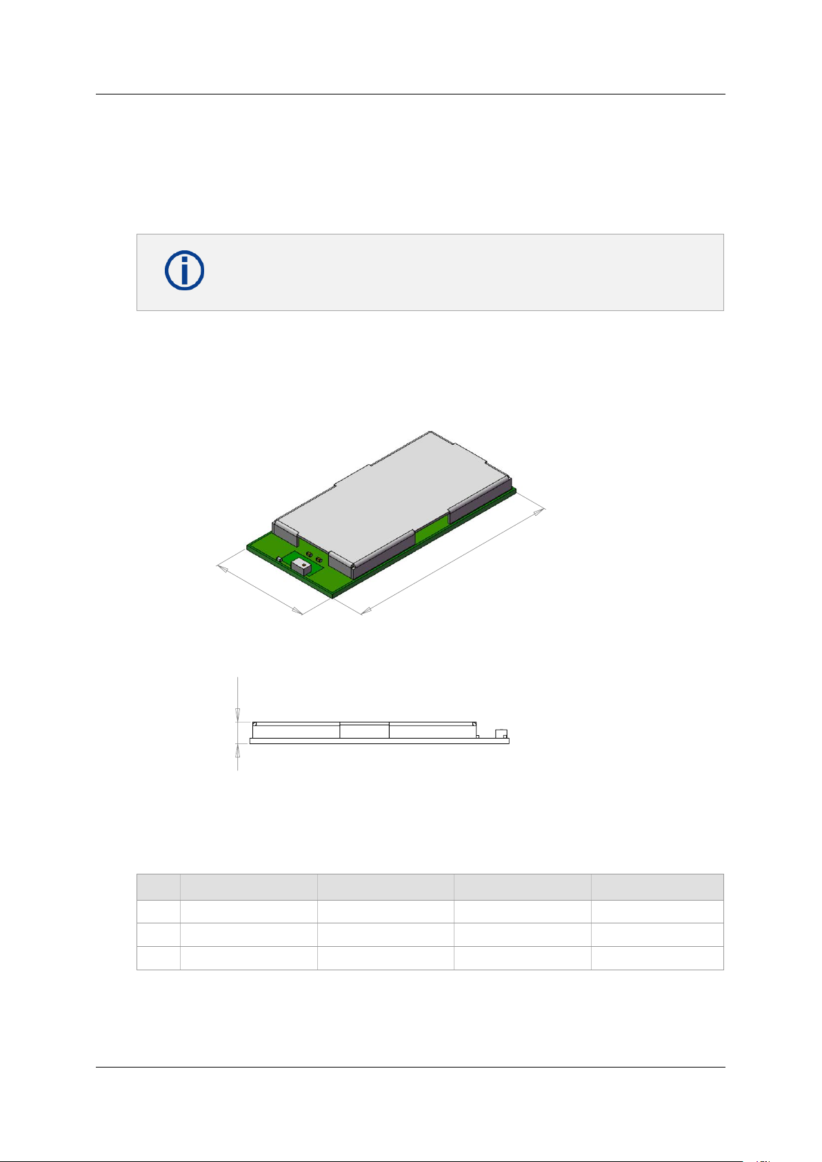
29
13,50
2,66
All dimensions are in millimeters.
No.
Item
Dimension
Tolerance
Remark
1
Width
13.50
± 0.35
2 Length
29.00
± 0.35
3 Height
2.66
± 0.20
with case
3 Detailed Description
3 Detailed Description
3.1 Dimensions
Product Specification Rev. 1.1 Page 14
 Loading...